Systems and methods for controlling a power plant
Fetvedt
U.S. patent number 10,731,571 [Application Number 15/440,196] was granted by the patent office on 2020-08-04 for systems and methods for controlling a power plant. This patent grant is currently assigned to 8 Rivers Capital, LLC. The grantee listed for this patent is 8 Rivers Capital, LLC. Invention is credited to Jeremy Eron Fetvedt.


View All Diagrams
| United States Patent | 10,731,571 |
| Fetvedt | August 4, 2020 |
Systems and methods for controlling a power plant
Abstract
The present disclosure relates to systems and methods that are useful in control of one or more aspects of a power production plant. More particularly, the disclosure relates to power production plants, methods of starting power production plants, and methods of generating power with a power production plant wherein one or more control paths are utilized for automated control of at least one action. The present disclosure more particularly relates to power production plants, control systems for power production plants, and methods for startup of a power production plant.
| Inventors: | Fetvedt; Jeremy Eron (Raleigh, NC) | ||||||||||
|---|---|---|---|---|---|---|---|---|---|---|---|
| Applicant: |
|
||||||||||
| Assignee: | 8 Rivers Capital, LLC (Durham,
NC) |
||||||||||
| Family ID: | 1000004963836 | ||||||||||
| Appl. No.: | 15/440,196 | ||||||||||
| Filed: | February 23, 2017 |
Prior Publication Data
| Document Identifier | Publication Date | |
|---|---|---|
| US 20170248083 A1 | Aug 31, 2017 | |
Related U.S. Patent Documents
| Application Number | Filing Date | Patent Number | Issue Date | ||
|---|---|---|---|---|---|
| 62300504 | Feb 26, 2016 | ||||
| Current U.S. Class: | 1/1 |
| Current CPC Class: | F02C 9/263 (20130101); F02C 9/26 (20130101); F02C 3/34 (20130101); F02C 7/057 (20130101); F02C 9/20 (20130101); F02C 9/54 (20130101); F05D 2270/303 (20130101); F05D 2220/32 (20130101); F05D 2270/335 (20130101); F05D 2270/306 (20130101); F05D 2220/76 (20130101); F02C 9/32 (20130101); F02C 9/34 (20130101); F02C 9/16 (20130101); F05D 2270/053 (20130101) |
| Current International Class: | F02C 9/54 (20060101); F02C 9/20 (20060101); F02C 9/34 (20060101); F02C 9/16 (20060101); F02C 7/057 (20060101); F02C 3/34 (20060101); F02C 9/26 (20060101); F02C 9/32 (20060101) |
References Cited [Referenced By]
U.S. Patent Documents
| 3369361 | February 1968 | Craig |
| 3376706 | April 1968 | Angelino |
| 3503208 | March 1970 | Schmidt |
| 3544291 | December 1970 | Schlinger et al. |
| 3736745 | June 1973 | Karig |
| 3837788 | September 1974 | Craig et al. |
| 3868817 | March 1975 | Marion et al. |
| 3971211 | July 1976 | Wethe et al. |
| 3976443 | August 1976 | Paull et al. |
| 4132065 | January 1979 | McGann |
| 4154581 | May 1979 | Nack et al. |
| 4191500 | March 1980 | Oberg et al. |
| 4193259 | March 1980 | Muenger et al. |
| 4206610 | June 1980 | Santhanam |
| 4275557 | June 1981 | Marvin |
| 4350008 | September 1982 | Zickwolf, Jr. |
| 4434613 | March 1984 | Stahl |
| 4498289 | February 1985 | Osgerby |
| 4522628 | June 1985 | Savins |
| 4602483 | July 1986 | Wilks et al. |
| 4702747 | October 1987 | Meyer et al. |
| 4721420 | January 1988 | Santhanam et al. |
| 4735052 | April 1988 | Maeda |
| 4765143 | August 1988 | Crawford et al. |
| 4765781 | August 1988 | Wilks et al. |
| 4839030 | June 1989 | Comolli et al. |
| 4852996 | August 1989 | Knop et al. |
| 4881366 | November 1989 | Nurse |
| 4957515 | September 1990 | Hegarty |
| 4999992 | March 1991 | Nurse |
| 4999995 | March 1991 | Nurse |
| 5175995 | January 1993 | Pak et al. |
| 5247791 | September 1993 | Pak et al. |
| 5265410 | November 1993 | Hisatome |
| 5345756 | September 1994 | Jahnke et al. |
| 5353721 | October 1994 | Mansour et al. |
| 5394686 | March 1995 | Child et al. |
| 5415673 | May 1995 | Hilton et al. |
| 5421166 | June 1995 | Allam et al. |
| 5507141 | April 1996 | Stigsson |
| 5520894 | May 1996 | Heesink et al. |
| 5533329 | July 1996 | Ohyama |
| 5590519 | January 1997 | Almlof et al. |
| 5595059 | January 1997 | Huber et al. |
| 5692890 | December 1997 | Graville |
| 5709077 | January 1998 | Beichel |
| 5715673 | February 1998 | Beichel |
| 5724805 | March 1998 | Golomb et al. |
| 5802840 | September 1998 | Wolf |
| 5906806 | May 1999 | Clark |
| 5937652 | August 1999 | Abdelmalek |
| 6024029 | February 2000 | Clark |
| 6092362 | July 2000 | Nagafuchi |
| 6148602 | November 2000 | Demetri |
| 6170264 | January 2001 | Viteri et al. |
| 6196000 | March 2001 | Fassbender |
| 6199364 | March 2001 | Kendall et al. |
| 6202574 | March 2001 | Liljedahl et al. |
| 6209307 | April 2001 | Hartman |
| 6260348 | July 2001 | Sugishita et al. |
| 6263661 | July 2001 | Van der Burgt et al. |
| 6269624 | August 2001 | Frutschi et al. |
| 6289666 | September 2001 | Ginter |
| 6298664 | October 2001 | .ANG.sen et al. |
| 6333015 | December 2001 | Lewis |
| 6389814 | May 2002 | Viteri et al. |
| 6430916 | August 2002 | Sugishita et al. |
| 6532745 | March 2003 | Neary |
| 6536205 | March 2003 | Sugishita et al. |
| 6543214 | April 2003 | Sasaki et al. |
| 6550234 | April 2003 | Guillard |
| 6598398 | July 2003 | Viteri et al. |
| 6612113 | September 2003 | Guillard |
| 6622470 | September 2003 | Viteri et al. |
| 6629414 | October 2003 | Fischer |
| 6637183 | October 2003 | Viteri et al. |
| 6684643 | February 2004 | Frutschi |
| 6764530 | July 2004 | Iijima |
| 6775987 | August 2004 | Sprouse et al. |
| 6802178 | October 2004 | Sprouse et al. |
| 6820689 | November 2004 | Sarada |
| 6824710 | November 2004 | Viteri et al. |
| 6871502 | March 2005 | Marin et al. |
| 6877319 | April 2005 | Linder et al. |
| 6877322 | April 2005 | Fan |
| 6898936 | May 2005 | Ochs et al. |
| 6910335 | June 2005 | Viteri et al. |
| 6918253 | July 2005 | Fassbender |
| 6945029 | September 2005 | Viteri |
| 6945052 | September 2005 | Frutschi et al. |
| 6993912 | February 2006 | Fischer |
| 7007474 | March 2006 | Ochs et al. |
| 7007486 | March 2006 | Sprouse et al. |
| 7021063 | April 2006 | Viteri |
| 7022168 | April 2006 | Schimkat et al. |
| 7043920 | May 2006 | Viteri et al. |
| 7074033 | July 2006 | Neary |
| 7089743 | August 2006 | Frutschi et al. |
| 7111463 | September 2006 | Sprouse et al. |
| 7124589 | October 2006 | Neary |
| 7147461 | December 2006 | Neary |
| 7191587 | March 2007 | Marin et al. |
| 7191588 | March 2007 | Tanaka |
| 7192569 | March 2007 | Stewart |
| 7281590 | October 2007 | Van de Waal |
| 7284362 | October 2007 | Marin et al. |
| 7299637 | November 2007 | Becker |
| 7303597 | December 2007 | Sprouse et al. |
| 7328581 | February 2008 | Christensen et al. |
| 7334631 | February 2008 | Kato et al. |
| 7360639 | April 2008 | Sprouse et al. |
| 7363764 | April 2008 | Griffin et al. |
| 7377111 | May 2008 | Agnew |
| 7387197 | June 2008 | Sprouse et al. |
| 7402188 | July 2008 | Sprouse |
| 7469544 | December 2008 | Farhangi |
| 7469781 | December 2008 | Chataing et al. |
| 7516607 | April 2009 | Farhangi et al. |
| 7516609 | April 2009 | Agnew |
| 7547419 | June 2009 | Sprouse et al. |
| 7547423 | June 2009 | Sprouse et al. |
| 7553463 | June 2009 | Zauderer |
| 7615198 | November 2009 | Sprouse et al. |
| 7665291 | February 2010 | Anand et al. |
| 7717046 | May 2010 | Sprouse et al. |
| 7722690 | May 2010 | Shires et al. |
| 7731783 | June 2010 | Sprouse et al. |
| 7739874 | June 2010 | Nigro |
| 7740671 | June 2010 | Yows et al. |
| 7740672 | June 2010 | Sprouse |
| 7814975 | October 2010 | Hagen et al. |
| 7826054 | November 2010 | Zillmer et al. |
| 7827797 | November 2010 | Pronske et al. |
| 7874140 | January 2011 | Fan et al. |
| 7882692 | February 2011 | Pronske et al. |
| 7927574 | April 2011 | Stewart |
| 7934383 | May 2011 | Gutierrez |
| 7950243 | May 2011 | Gurin |
| 7966829 | June 2011 | Finkenrath et al. |
| 8043588 | October 2011 | Hustad et al. |
| 8088196 | January 2012 | White et al. |
| 8099227 | January 2012 | Shafique |
| 8109095 | February 2012 | Henriksen et al. |
| 8220248 | July 2012 | Wijmans et al. |
| 8596075 | December 2013 | Allam et al. |
| 8776532 | July 2014 | Allam et al. |
| 8826670 | September 2014 | Hoffmann |
| 8850789 | October 2014 | Evulet et al. |
| 8959887 | February 2015 | Allam et al. |
| 8986002 | March 2015 | Palmer et al. |
| 9068743 | June 2015 | Palmer et al. |
| 2002/0134085 | September 2002 | Frutschi |
| 2003/0131582 | July 2003 | Anderson et al. |
| 2003/0221409 | December 2003 | McGowan |
| 2004/0011057 | January 2004 | Huber |
| 2004/0112037 | June 2004 | Yagi |
| 2004/0123601 | July 2004 | Fan |
| 2004/0134197 | July 2004 | Marin |
| 2005/0126156 | June 2005 | Anderson et al. |
| 2006/0242907 | November 2006 | Sprouse et al. |
| 2007/0180768 | August 2007 | Briesch et al. |
| 2007/0274876 | November 2007 | Chiu et al. |
| 2008/0010967 | January 2008 | Griffin et al. |
| 2008/0104958 | May 2008 | Finkenrath et al. |
| 2008/0115500 | May 2008 | MacAdam et al. |
| 2008/0166672 | July 2008 | Schlote et al. |
| 2008/0187877 | August 2008 | Fitzsimmons et al. |
| 2008/0190214 | August 2008 | Ubowski et al. |
| 2008/0309087 | December 2008 | Evulet et al. |
| 2009/0025390 | January 2009 | Christensen et al. |
| 2009/0061264 | March 2009 | Agnew |
| 2009/0130660 | May 2009 | Faham et al. |
| 2009/0150040 | June 2009 | Rofka |
| 2009/0229271 | September 2009 | Ruyck et al. |
| 2009/0260585 | October 2009 | Hack et al. |
| 2009/0301054 | December 2009 | Simpson et al. |
| 2010/0018218 | January 2010 | Riley et al. |
| 2010/0024378 | February 2010 | Ackermann et al. |
| 2010/0024381 | February 2010 | Ackermann et al. |
| 2010/0024433 | February 2010 | Ackermann et al. |
| 2010/0031668 | February 2010 | Kepplinger |
| 2010/0077752 | April 2010 | Papile |
| 2010/0300063 | December 2010 | Palmer et al. |
| 2010/0326084 | December 2010 | Anderson et al. |
| 2011/0036011 | February 2011 | Sprouse et al. |
| 2011/0012773 | June 2011 | Freund et al. |
| 2011/0179799 | July 2011 | Allam et al. |
| 2011/0185701 | August 2011 | Koda et al. |
| 2011/0233940 | September 2011 | Aoyama et al. |
| 2011/0239651 | October 2011 | Aoyama et al. |
| 2012/0067054 | March 2012 | Palmer et al. |
| 2012/0067056 | March 2012 | Palmer et al. |
| 2012/0073261 | March 2012 | Palmer et al. |
| 2012/0237881 | September 2012 | Allam et al. |
| 2013/0104525 | May 2013 | Allam et al. |
| 2013/0118145 | May 2013 | Palmer et al. |
| 2013/0199195 | August 2013 | Allam et al. |
| 2013/0205746 | August 2013 | Allam et al. |
| 2013/0213049 | August 2013 | Allam et al. |
| 2013/0229018 | September 2013 | Karni |
| 2013/0327050 | December 2013 | Slobodyanskiy |
| 2014/0000271 | January 2014 | Mittricker et al. |
| 2014/0053529 | February 2014 | Allam et al. |
| 2014/0331687 | November 2014 | Palmer et al. |
| 2015/0020497 | January 2015 | Iwai et al. |
| 2015/0027099 | January 2015 | Iwai et al. |
| 2015/0059313 | March 2015 | Itoh et al. |
| 2018/0156127 | June 2018 | Hausmann |
| 1898499 | Jan 2007 | CN | |||
| 101201171 | Jun 2008 | CN | |||
| 101324203 | Dec 2008 | CN | |||
| 102834670 | Dec 2012 | CN | |||
| 103221640 | Jul 2013 | CN | |||
| 1698829 | Sep 2006 | EP | |||
| 2225905 | Sep 1990 | JP | |||
| 6-26362 | Feb 1994 | JP | |||
| 3110114 | Nov 2000 | JP | |||
| 2000-337107 | Dec 2000 | JP | |||
| 2001-132472 | May 2001 | JP | |||
| 3454372 | Oct 2003 | JP | |||
| WO 95/12757 | May 1995 | WO | |||
| WO 2009/041617 | Apr 2009 | WO | |||
| WO 2012/003079 | Jan 2012 | WO | |||
Other References
|
Allam et al., "High Efficiency and Low Cost of Electricity Generation from Fossil Fuels While Eliminating Atmospheric Emissions, Including Carbon Dioxide," GHGT-11, Energy Procedia 00, 2012, pp. 1-12. cited by applicant . Combs, Jr. "An Investigation of the Supercritical CO2 Cycle (Feher Cycle) for Shipboard Application," 1977, Submitted in Partial Fulfillment of the Requirements for the Degree of Ocean Engineer and the Degree of Master of Science in Mechanical Engineering at the Massachusetts Institute of Technology, 148. cited by applicant . Dostal et al., "A Supercritical Carbon Dioxide Cycle for Next Generation Nuclear Reactors," 2004, (Research Paper) Advanced Nuclear Power Technology Program at MIT, 326 pages. cited by applicant . Hong et al., "Analysis of Oxy-Fuel Combustion Power Cycle Utilizing a Pressurized Coal Combustor," Energy, Available Online Jun. 21, 2009, pp. 1332-1340, vol. 34, No. 9. cited by applicant . Iantovski et al., "Highly Efficient Zero Emission CO2-Based Power Plant" Energy Conyers. Mgmt, 1997, Suppl. pp. S141-S146, vol. 38. cited by applicant . Mathieu et al., "Sensitivity Analysis of the MATIANT Cycle", Energy Conversion & Management, 1999, pp. 1687-1700, vol. 40. cited by applicant . Wall et al., "A Zero Emission Combustion Power Plant for Enhances Oil Recovery," Energy, 1995, pp. 823-828, vol. 20, No. 8. cited by applicant . Yantovskii et al. , "Computer Exergonomics of Power Plants Without Exhaust Gases," Energy Conyers. Mgmt., Publ. 1992, vol. 33, No. 5-8, pp. 405-412. cited by applicant . http://www.graz-cycle.tugraz.at/pdfs/Bolland_Kvamsdal_Boden_Liege.pdf; Boland, "A Thermodynamic Comparison of the Oxy-Fuel Power Cycles Water-Cycle, Graz-Cycle and Matiant-Cycle," Norwegian University of Science and Technology, Trondheim, Norway. cited by applicant . http://www2.ulg.ac.be/genienuc/pageco2.htm; Universite de Liege, Department of Power Generation, "CO2 Researches". cited by applicant. |
Primary Examiner: Sung; Gerald L
Assistant Examiner: Mcglynn; James P
Attorney, Agent or Firm: Womble Bond Dickinson (US) LLP
Parent Case Text
CROSS-REFERENCE TO RELATED APPLICATIONS
The present application claims priority to U.S. Provisional Application No. 62/300,504, filed Feb. 26, 2016, the disclosure of which is incorporated herein by reference.
Claims
The invention claimed is:
1. A control system for a power production plant, the control system comprising a flow control logic sequence adapted for: receiving a POWER ACTUAL signal that relays an actual power production by the power production plant at a given time; receiving a POWER DEMAND signal that relays a desired power production by the plant at the same given time; calculating a first differential between the POWER DEMAND signal and the POWER ACTUAL signal and converting the first differential into a FUEL FLOW DEMAND signal indicating a desired flow of a fuel to a combustor; generating a TURBINE INLET TEMPERATURE signal representing a temperature of an inlet of a turbine, the TURBINE INLET TEMPERATURE signal being a selection of the highest of a plurality of calculated temperature signals each respectively derived from different calculation routines for calculating the temperature at the inlet of the turbine; calculating a second differential between the TURBINE INLET TEMPERATURE signal and a maximum turbine inlet temperature; and regulating one or both of a mass and a pressure of the fuel flowing from a fuel supply system to the combustor based upon a selection of the lower of the FUEL FLOW DEMAND signal and the second differential.
2. The control system according to claim 1, wherein the control system is adapted to adjust a ratio of a mass or a volume of fuel flowing through two or more different fuel lines from the fuel supply system to the combustor.
3. The control system according to claim 2, wherein the control system is adapted to open/close flow control valves in each of the two or more different fuel lines.
4. The control system according to claim 3, wherein the control system is adapted to open/close at least one pressure control valve in each of the two or more different fuel lines.
5. The control system according to claim 2, wherein the control system is adapted to adjust a ratio of a mass or a volume of oxidant flowing through two or more different oxidant lines from an oxidant supply system to the combustor.
6. The control system according to claim 5, wherein the control system is adapted to adjust a fuel to oxidant ratio in one of the two or more fuel lines and one of the two or more oxidant lines independent of a fuel to oxidant ratio in another of the two or more fuel lines and another of the two or more oxidant lines.
7. The control system according to claim 5, wherein the power production plant includes a line providing a stream of recycled CO.sub.2, wherein a portion of the stream of recycled CO.sub.2 is added to one or more of the two or more oxidant lines, and wherein the control system is adapted to adjust an oxygen concentration in one or more of the two or more oxidant lines by adjusting an amount of the recycled CO.sub.2 that is added to the oxidant line.
8. The control system according to claim 7, wherein the oxygen concentration in each of the one or more oxidant lines is adjusted independently from the remaining oxidant lines.
9. The control system according to claim 7, wherein the control system is adapted to adjust an equivalence ratio between the mass or volume of oxidant flowing through one of the two or more oxidant lines and another of the two or more oxidant lines.
10. The control system according to claim 2, wherein the control system is adapted to close a flow control valve in a primary fuel line from the two or more fuel lines to the combustor so that substantially no fuel flows through the primary fuel line and is adapted to open a flow control valve in a secondary fuel line from the two or more fuel lines to the combustor so that substantially all of the fuel flowing to the combustor is flowing through the secondary fuel line.
11. The control system according to claim 10, wherein the control system is adapted to adjust an equivalence ratio between the mass or volume of fuel flowing through the primary fuel line and the secondary fuel line.
12. The control system according to claim 10, wherein the control system is adapted to provide a configuration of the flow control valve in the primary fuel line and the flow control valve in the secondary fuel line during startup of the power production plant and is configured to synchronize opening of the valve in the primary fuel line with a working condition of one or both of the turbine and a compressor that compresses a stream of recycled CO.sub.2 flowing to the combustor.
13. The control system according to claim 2, wherein the control system is adapted to hold or lower the mass or volume of fuel flowing through at least one of the two or more different fuel lines from the fuel supply system to the combustor in response to an input signal indicating an operating temperature of a heat exchanger is approaching or exceeding a predefined operating maximum temperature or rate of heat increase.
14. A power production plant comprising: a combustor; a turbine; a generator; a fuel supply system; an oxidant supply system; a control system having a plurality of control paths for automated control of at least one act in operation of the power production plant, said control system including a control path adapted to generate a control signal that is a function of: a comparison of a POWER ACTUAL signal relaying an actual power production by the power production plant at a given time and a POWER DEMAND signal relaying a desired power production by the plant at the same given time to generate a FUEL FLOW DEMAND signal for flow of a fuel to the combustor; generation of a TURBINE INLET TEMPERATURE signal for a temperature of an inlet of the turbine by a selection of the highest of a plurality of calculated temperature signals each respectively derived from different calculation routines for calculating the temperature at the inlet of the turbine; and calculation of a differential between the TURBINE INLET TEMPERATURE signal and a maximum turbine inlet temperature; said control path including a logic sequence adapted for selecting the lower of the FUEL FLOW DEMAND signal and the differential, and said generated control signal being effective to regulate one or both of the mass and pressure of fuel flowing from the fuel supply system to the combustor.
15. The power production plant of claim 14, wherein the fuel supply system comprises at least two separately controlled fuel lines configured for passage of fuel to the combustor.
16. The power production plant of claim 15, wherein the oxidant supply system comprises at least two separately controlled oxidant lines configured for passage of oxidant to the combustor.
17. The power production plant of claim 16, wherein the oxidant supply system comprises at least one flow control valve in each of the at least two separately controlled oxidant lines.
18. The power production plant of claim 17, wherein the control system is further configured to output one or more further control signals to one or more of the at least one flow control valve in each of the at least two separately controlled oxidant lines so as to adjust the mass or volume of oxidant flowing through the at least two separately controlled oxidant lines and thereby adjust an equivalence ratio between the mass or volume of oxidant flowing through the at least two separately controlled oxidant lines.
19. The power production plant of claim 18, wherein one of the at least two separately controlled oxidant lines is a secondary oxidant flow line that comprises a flow sensor, wherein one of the at least two separately controlled fuel lines is a secondary fuel flow line that comprises a flow sensor, and wherein the control system is further configured to output one or more further control signals to open or close the flow control valve in the secondary oxidant flow line based upon a mass or volume flow of fuel through the secondary fuel flow line.
20. The power production plant of claim 15, wherein the fuel supply system comprises at least one flow control valve and at least one pressure control valve in each of the at least two separately controlled fuel lines.
Description
FIELD OF THE DISCLOSURE
The presently disclosed subject matter relates to systems and methods for controlling the various aspects of a power plant. More particularly, the systems and methods can utilize a variety of signals and functions to control pressures, temperatures, fluid flows, switches, valves, and the like during multiples phases of the start-up, running, and shut-down of a power plant.
BACKGROUND
As the world-wide demand for electrical power production increases there is a continuing need for additional power production plants to meet such needs. Because of market demands, it is desirable for such power production to be achieved with the greatest possible efficiency; however, growing requirements for carbon capture have required technological advances. For example, U.S. Pat. No. 8,596,075 to Allam et al., the disclosure of which is incorporated herein by reference, provides for desirable efficiencies in oxy-fuel combustion systems utilizing a recycle CO.sub.2 stream wherein the CO.sub.2 is captured as a relatively pure stream at high pressure. Such advanced power production systems require control considerations that have not heretofore been provided. Accordingly, there is a need for further systems and methods suitable for controlling multiple aspects of power plants, particularly power plants configured for high efficiency power production with substantially complete carbon capture.
SUMMARY OF THE DISCLOSURE
The present disclosure provides systems and methods for power production wherein one or more control paths are utilized for automated control of one or more actions. The automated controls can be based upon a variety of signal inputs, calculated values, pre-set values, measured values, logical functions, computer algorithms, or computer program inputs.
In one or more embodiments, the present disclosure can relate to a control system for a power production plant. For example, the control system can comprise a flow control logic sequence adapted for selecting the lower of a FUEL FLOW DEMAND signal for flow of a fuel to a combustor and a TURBINE INLET TEMPERATURE signal for a temperature of an inlet of a turbine, and regulating one or both of a mass and a pressure of the fuel flowing from a fuel supply system to the combustor. In further embodiments, the control system for a power production plant can be described in relation to any one or more of the following statements, which may be combined in any number or order.
The control system can comprise: a POWER ACTUAL signal relaying the actual power production by the power production plant at a given time; and a POWER DEMAND signal relaying the desired power production by the plant at the same given time; wherein the control system is configured to calculate a differential between the POWER DEMAND signal and the POWER ACTUAL signal and to convert the differential into the FUEL FLOW DEMAND signal.
The control system can generate the TURBINE INLET TEMPERATURE signal as a selection of the highest of a plurality of calculated temperature signals each respectively derived from different calculation routines for calculating the temperature at the inlet of the turbine.
The control system can be adapted to adjust a ratio of a mass or a volume of fuel flowing through two or more different fuel lines from the fuel supply system to the combustor.
The control system can be adapted to open/close flow control valves in each of the two or more different fuel lines.
The control system can be adapted to open/close at least one pressure control valve in each of the two or more different fuel lines.
The control system can be adapted to adjust a ratio of a mass or a volume of oxidant flowing through two or more different oxidant lines from an oxidant supply system to the combustor.
The power production plant can include at least a primary set of fuel and oxidant lines and a secondary set of fuel and oxidant lines, and wherein the control system is adapted to adjust a fuel to oxidant ratio in the primary set of fuel and oxidant lines independent of a fuel to oxidant ratio in the secondary set of fuel and oxidant lines.
The power production plant can include a line providing a stream of recycled CO.sub.2, wherein a portion of the stream of recycled CO.sub.2 is added to one or more of the oxidant lines, and wherein the control system is adapted to adjust an oxygen concentration in one or more of the oxidant lines by adjusting an amount of the recycled CO.sub.2 that is added to the oxidant line.
The oxygen concentration in each of the one or more oxidant lines can be adjusted independently from the remaining oxidant lines.
The can be adapted to adjust an equivalence ratio between the mass or volume of oxidant flowing through the primary oxidant line and the secondary oxidant line.
The control system can be adapted to close a flow control valve in a primary fuel line from the fuel supply system to the combustor so that substantially no fuel flows through the primary fuel line and is adapted to open a flow control valve in a secondary fuel line from the fuel supply system to the combustor so that substantially all of the fuel flowing to the combustor is flowing through the secondary fuel line.
The control system can be adapted to adjust an equivalence ratio between the mass or volume of fuel flowing through the primary fuel line and the secondary fuel line.
The control system can be adapted to provide the configuration of the flow control valve in the primary fuel line and the flow control valve in the secondary fuel line during startup of the power production plant and is configured to synchronize opening of the valve in the primary fuel line with a working condition of one or both of the turbine and a compressor that compresses a stream of recycled CO.sub.2 flowing to the combustor.
The control system can be adapted to hold or lower the mass or volume of fuel flowing through at least one of the two or more different fuel lines from the fuel supply system to the combustor in response to an input signal indicating an operating temperature of a heat exchanger is approaching or exceeding a predefined operating maximum temperature or rate of heat increase.
In one or more embodiments, the present disclosure further can relate to a power production system. For example, a power production plant according to the present disclosure can comprise: a combustor; a turbine; a generator; a fuel supply system; an oxidant supply system; a control system having a plurality of control paths for automated control of at least one act in operation of the power production plant, said control system including: a control path adapted to generate a control signal that is a function of a comparison of a FUEL FLOW DEMAND signal for flow of a fuel to the combustor and a TURBINE INLET TEMPERATURE signal for a temperature of an inlet of the turbine, said fuel flow control path including a logic sequence adapted for selecting the lower of the FUEL FLOW DEMAND signal and the TURBINE INLET TEMPERATURE signal, and said generated control signal being effective to regulate one or both of the mass and pressure of fuel flowing from the fuel supply system to the combustor. In further embodiments, the power production system can be described in relation to any one or more of the following statements, which may be combined in any number or order.
The FUEL FLOW DEMAND signal can be a function of a comparison of a POWER ACTUAL signal relaying the actual power production by the power production plant at a given time and a POWER DEMAND signal relaying the desired power production by the plant at the same given time.
The control system can be configured to generate the TURBINE INLET TEMPERATURE signal as a selection of the highest of a plurality of calculated temperature signals each respectively derived from different calculation routines for calculating the temperature at the inlet of the turbine.
The fuel supply system can comprise at least two separately controlled fuel lines configured for passage of fuel to the combustor.
The fuel supply system can comprise at least one flow control valve and at least one pressure control valve in each of the at least two separately controlled fuel lines.
The oxidant supply system can comprise at least two separately controlled oxidant lines configured for passage of oxidant to the combustor.
The oxidant supply system can comprise at least one flow control valve in each of the at least two separately controlled oxidant lines.
The oxidant supply system can comprise an equivalence ratio control element configured to adjust an equivalence ratio between the mass or volume of oxidant flowing through the at least two separately controlled oxidant lines.
The power production plant can be configured such that one of the at least two separately controlled oxidant lines is a secondary oxidant flow line that comprises a flow sensor, wherein one of the at least two separately controlled fuel lines is a secondary fuel flow line that comprises a flow sensor, and wherein the control system includes a ratio control element configured to open or close the flow control valve in the secondary oxidant flow line based upon a mass or volume flow of fuel through the secondary fuel flow line.
In additional embodiments, the present disclosure also can relate to methods for start-up of a power production plant. For example, such methods can comprise executing a series of control signals wherein: a flow valve in a secondary fuel flow line is at least partially opened so that fuel from a fuel source begins to flow to a combustor while substantially no fuel flows from the fuel source to the combustor in a primary fuel flow line; a flow valve in a secondary oxidant flow line is at least partially opened so that oxidant from an oxidant source begins to flow to the combustor while substantially no oxidant flows from the oxidant source to the combustor in a primary oxidant flow line; a turbine is ramped up from a first speed to a second, higher speed; after the turbine is ramped to at least the second speed, an equivalence ratio of fuel flow in the primary fuel flow line to fuel flow in the secondary fuel flow line is adjusted so that a valve in the primary fuel flow line is opened, and fuel from the fuel source flows to the combustor in the primary fuel flow line; and after the turbine is ramped to at least the second speed, an equivalence ratio of oxidant flow in the primary oxidant flow line to oxidant flow in the secondary oxidant flow line is adjusted so that a valve in the primary oxidant flow line is opened, and oxidant from the oxidant source flows to the combustor in the primary oxidant flow line.
BRIEF DESCRIPTION OF THE FIGURES
Reference will now be made to the accompanying drawings, which are not necessarily drawn to scale, and wherein:
FIG. 1 is a flow diagram for a power production plant according to embodiments of the present disclosure;
FIG. 2 is a function block diagram showing control paths carried out by a control system in operation of a power production plant according to embodiments of the present disclosure;
FIG. 3 is a flow diagram for a fuel gas system and certain control elements therefor as used in a power production plant according to embodiments of the present disclosure;
FIG. 4a is SHEET 1 of a series of function block diagrams, FIG. 4a showing control paths useful in, for example, steady state and power control demand for a power production plant according to embodiments of the present disclosure;
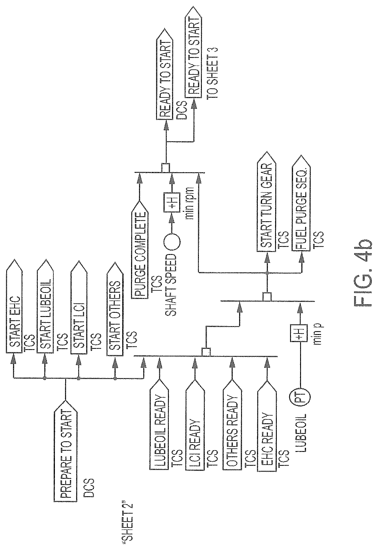
FIG. 4b is SHEET 2 of the series of function block diagrams, FIG. 4b showing control paths useful in, for example, initiating start-up for a power production plant according to embodiments of the present disclosure;
FIG. 4c is SHEET 3 of the series of function block diagrams, FIG. 4c showing control paths useful in, for example, initiating turbine crank and load commutated inverter (LCI) reference during start-up of a power production plant according to embodiments of the present disclosure;
FIG. 4d is SHEET 4 of the series of function block diagrams, FIG. 4d showing control paths useful in, for example, cranking and ignition during start-up of a power production plant according to embodiments of the present disclosure;
FIG. 4e is SHEET 5 of the series of function block diagrams, FIG. 4e showing control paths useful in, for example, ignition during start-up of a power production plant according to embodiments of the present disclosure;
FIG. 4f is SHEET 6 of the series of function block diagrams, FIG. 4f showing control paths useful in, for example, meeting fuel demand during start-up of a power production plant according to embodiments of the present disclosure;
FIG. 4g is SHEET 7 of the series of function block diagrams, FIG. 4g showing control paths useful in, for example, heat exchanger protection and calculating combustion ratios for a power production plant according to embodiments of the present disclosure;
FIG. 4h is SHEET 8 of the series of function block diagrams, FIG. 4h showing control paths useful in, for example, generator synchronization for a power production plant according to embodiments of the present disclosure;
FIG. 4i is SHEET 9 of the series of function block diagrams, FIG. 4i showing control paths useful in, for example, calculating turbine inlet temperature in a power production plant according to embodiments of the present disclosure;
FIG. 4j is SHEET 10 of the series of function block diagrams, FIG. 4j showing control paths useful in, for example, controlling fuel pressure control valves and discharge pressure set points in a power production plant according to embodiments of the present disclosure;
FIG. 4k is SHEET 11 of the series of function block diagrams, FIG. 4k showing control paths useful in, for example, establishing oxidant discharge pressure set point in a power production plant according to embodiments of the present disclosure;
FIG. 4l is SHEET 12 of the series of function block diagrams, FIG. 4l showing control paths useful in, for example, configuring turbine blade cooling temperatures and flow set points in a power production plant according to embodiments of the present disclosure;
FIG. 4m is SHEET 13 of the series of function block diagrams, FIG. 4m showing control paths useful in, for example, turbine thrust control in a power production plant according to embodiments of the present disclosure;
FIG. 4n is SHEET 14 of the series of function block diagrams, FIG. 4n showing control paths useful in, for example, controlling fuel line purge flows in a power production plant according to embodiments of the present disclosure; and
FIG. 5 shows a flow diagram including a plurality of functional components and control elements for a power production plant according to embodiments of the present disclosure.
DETAILED DESCRIPTION
The present subject matter will now be described more fully hereinafter with reference to exemplary embodiments thereof. These exemplary embodiments are described so that this disclosure will be thorough and complete, and will fully convey the scope of the subject matter to those skilled in the art. Indeed, the subject matter can be embodied in many different forms and should not be construed as limited to the embodiments set forth herein; rather, these embodiments are provided so that this disclosure will satisfy applicable legal requirements. As used in the specification, and in the appended claims, the singular forms "a", "an", "the", include plural referents unless the context clearly dictates otherwise.
The present disclosure relates to systems and methods adapted for controlling one or more actions in the operation of a power production plant. As such, the present disclosure further relates to power production plants including a variety of elements, including such control systems. Non-limiting examples of elements that may be included in a power production plant according to the present disclosure are described in U.S. Pat. Nos. 8,596,075, 8,776,532, 8,959,887, 8,986,002, 9,068,743, U.S. Pat. Pub. No. 2010/0300063, U.S. Pat. Pub. No. 2012/0067054, U.S. Pat. Pub. No. 2012/0237881, and U.S. Pat. Pub. No. 2013/0213049, the disclosures of which are incorporated herein by reference.
In one or more embodiments, a power production plant may include some combination of the elements shown in FIG. 1 (although it is understood that further elements may also be included). As seen therein, a power production plant 100 can include a combustor 111 configured to receive fuel from a fuel supply 115 and oxidant from an oxidant supply 120. Fuel can flow from the fuel supply 115 in a primary fuel line 116 and/or a secondary fuel line 117. The fuel supply 115 and the fuel supply lines 116, 117 can form a fuel system. Oxidant likewise can flow from the oxidant supply 120 in a primary oxidant line 121 and/or a secondary oxidant line 122. The oxidant supply 120 and the oxidant supply lines 121, 122 can from an oxidant system. While a plurality of fuel supply lines and oxidant supply lines are illustrated, it is understood that only a single fuel supply line may be used and/or only a single oxidant supply line may be used. Likewise, more than two fuel supply lines may be used and/or more than two oxidant supply lines may be used. The fuel is combusted in the combustor 111 with the oxidant in the presence of a recycle CO.sub.2 stream provided in line 160 and/or in line 121 in admixture with the oxidant and/or in line 122 in admixture with the oxidant. The combustion product stream in line 112 is expanded across a turbine 125 to produce power with a combined generator 130. Although the combustor 111 and turbine 125 are illustrated as separate elements, it is understood that, in some embodiments, a turbine may be configured so as to be inclusive of the combustor. In other words, a single turbine unit may include a combustion section and an expansion section. Accordingly, discussion herein of passage of streams into a combustor may also be read as passage of streams into a turbine that is configured for combustion as well as expansion.
Turbine exhaust in stream 126 is cooled in a heat exchanger 135. Although a single heat exchanger 135 is illustrated, it is understood that the heat exchanger may be a single unit with a plurality of sections operating in different temperature ranges. Likewise, a plurality of separate heat exchangers operating in different temperature ranges may be utilized. Water is separated through water line 141 in the separator 140 to produce a substantially pure recycle CO.sub.2 stream 145 (although part of the stream may be withdrawn from the plant and/or diverted to other parts of the plant (e.g., for cooling the turbine) or to other lines (e.g., for combination with the oxidant and/or the fuel). The recycle CO.sub.2 stream 145 is compressed in a multi-stage compressor including a first stage compressor 151, a second stage compressor 155, and an inter-stage cooler 153. Optionally, one or more further compressors or pumps may be added. Further, the compressor need not be a multi-stage compressor. The compressed recycle CO.sub.2 stream in line 160 is passed back through the heat exchanger to the combustor. All or part of the recycle CO.sub.2 stream in line 160 may be passed directly to the combustor 111. As illustrated in lines 161, 161a, and 161b, all or part of the recycle CO.sub.2 stream can be input to one or both of the primary oxidant line 117 and the secondary oxidant line 122. Although not illustrated, it is understood that one or both of lines 161 and 161b may alternatively or additional provide CO.sub.2 to one or both of the fuel supply lines 116, 117.
The illustrated power production plant further includes a control system 170 that has a plurality of control paths (CP1, CP2, CP3, and CP4 as illustrated) that are configured to provide for automated control of at least one act in operation of the power production plant. Each control path can be configured for generating at least one control signal (SIG 1, SIG 2, SIG 3, and SIG 4) that is effective to cause one or more responsive actions to occur. Non-limiting examples of such responsive actions can include executing a computer subroutine, carrying out a mathematical calculation, executing a logic function, altering the state of a valve, altering the mass flow of a fluid stream, altering the pressure of a fluid stream, generating a further control signal, and the like. A single control path may be configured to generate a single control signal or may be configured to generate a plurality of signals. Moreover, the power production plant can include a single control system or may include a plurality of control systems. For example, the control system 170 may be a distributed control system (DCS) that can be configured for top down control of all components of the power production plant. If desired, one or more elements of the power production plant can have a separate control system that can function in combination with the DCS or substantially autonomously from the DCS. For example, a turbine control system (TCS) can function independently of the DCS. Further, the DCS can send signals to the TCS (and vice versa) in order to carry out various functions of the power production methods. Accordingly, the power plant can comprise a single control system, or the power plant can comprise a plurality of control systems. Further, one single control system can manage one or more sub-control systems. In FIG. 1, the control system 170 may be a TCS, and the system can include a separate DCS.
The control system or systems can be configured to address a variety of control needs. In some embodiments, a control system can particularly relate to manners of controlling power output of the power production plant. In some embodiments, a control system can particularly relate to manners of controlling fuel flow and/or oxidant flow in the power production system. In some embodiments, a control system can particularly relate to controls for providing a substantially steady state system. Non-limiting examples of steady state conditions subject to specific control paths and/or control signals include turbine inlet temperature monitors and alarms, oxidant demand signals, case cooling flow and temperature, nozzle cooling flow and temperature, blade cooling flow and temperature, balance piston control, and heat exchanger protection. In one or more embodiments, a plurality of control paths and/or control signals may be utilized in combination. For example, plant start-up may utilize multiple control paths and control signals to ensure that the plant transitions from a shut-down state to a running state in a safe and efficient manner. In particular, start-up may be executed utilizing a plurality of waypoints wherein the necessary working conditions of each waypoint must be properly achieved before the control system allows start-up to proceed to the next waypoint. Thus, the control system may be particularly configured to ensure that a plurality of steps is carried out in a defined sequence achieving a defined result. Accordingly, the present disclosure can particularly provide one or more methods for controlling one or more aspects of a power production combustion cycle.
Control functions as described herein can particularly relate to specific changes in one or more operating conditions of the power production system in respond to a control signal being delivered from a control element to a functional component of the power production system. For example, a control function can include opening and/or closing one or more valves, increasing or decreasing pressure in a specific flow line, increasing or decreasing flow rate through a flow line, increasing or decreasing compression in a compressor or pump, and the like. Operational changes thus can be caused in response to a control signal from a control element. Further, the control signal may be generated by the control element based upon an input signal from one or more sensors, such as a pressure sensor, a flow sensor, a level sensor, and a temperature sensor.
In one or more embodiments, power output in a power production system can be adjusted by utilizing power demand as a control signal. As such, the present disclosure can relate to a control system comprising one or more control paths for a power production system as well as a system and method suitable for implementation of the control path(s). Embodiments of suitable control paths are illustrated in FIG. 2. The control paths shown in FIG. 2 are further shown in FIG. 4a (SHEET 1). The control paths illustrated in FIG. 2 illustrate embodiments whereby fuel flows and/or oxidant flows can be switched (automatically or manually) two or more lines--e.g., between a primary fuel line (or a high flow fuel line) and a secondary fuel line (or a low flow fuel line) or between a primary oxidant line (or a high flow oxidant line) and a secondary oxidant line (or a low flow oxidant line). The control paths enable the ability to utilize a variable equivalence ratio for the respective flows between the respective lines. For example, the control system can define one or more control paths specifically adapted to control the amount of fuel that is passed through the primary fuel line (116 in FIG. 1) and the secondary fuel line (117 in FIG. 1) and/or one or more control paths specifically adapted to control the amount of oxidant that is passed through the primary oxidant line (121 in FIG. 1) and the secondary oxidant line (122 in FIG. 1). Control of fuel flow and/or oxidant flow can include opening and closing one or more valves in response to a control signal from a control element. Further, the control signal may be generated by the control element based upon an input signal from one or more sensors. In particular embodiments, such control can apply specifically during start-up of the power plant and/or during a changeover period between startup and full operation. As used herein, "full operation" can indicate that the combustor is in operation, the turbine and the main compressor(s) are synchronized, and the turbine is operating at a speed sufficient to operate the generator for power production.
In FIG. 2, a POWER DEMAND signal 202 and a POWER ACTUAL signal 204 can be output by the DCS and the generator control system (GCS) respectively. POWER DEMAND conveys the power output that is required at a given time, and POWER ACTUAL conveys the actual power output at a given time as measured by the generator. POWER DEMAND is compared to POWER ACTUAL, and the differential calculated at waypoint 206 can be used to generate a FUEL FLOW DEMAND signal. The control sequence thus is configured to convert a POWER DEMAND signal into a fuel flow signal, which can signal fuel flow in the primary fuel line and secondary fuel line to be at varying ratios. The FUEL FLOW DEMAND signal is calculated at waypoint 208 or, in the alternative, the power-to-flow function can be configured for generation of a conventional fuel stroke reference (FSR) signal. For example, the function at waypoint 206 can have an output signal of 0% to 100% instead of outputting a fuel flow rate as otherwise noted above. If using FSR mode, the following controller may be placed under manual control. The FUEL FLOW DEMAND signal arising from the function at waypoint 208 can be modified with one or more additional requirements at waypoint 210. For example, the FUEL FLOW DEMAND signal can be modified with a fuel requirement signal, such as a start-up fuel (SU-FUEL) signal from a start-up sequence. During start-up, POWER DEMAND can be essentially zero, and the SU-FUEL signal will thus direct the fuel flow requirement. As the process proceeds past start-up, POWER DEMAND will increase, and the SU-FUEL signal will eventually transition to null. In this manner, fuel flow is automatically adjusted as the POWER DEMAND signal changes.
The FUEL FLOW DEMAND signal generated at waypoint 208 of the control path shown in FIG. 2 can be read by one controller or a plurality of controllers. Further, the FUEL FLOW DEMAND signal can be applied to a plurality of different fuel lines and oxidant lines, which can vary based upon the number of fuel lines utilized in the power production system. As illustrated in FIG. 1, the control system includes: a path whereby fuel flow through a fuel control valve in a primary line (e.g., line 116 in FIG. 1) is controlled; a path whereby fuel flow through a fuel control valve is a secondary line (e.g., line 117 in FIG. 1) is controlled; a path whereby oxidant flow through a secondary line (e.g., line 122 in FIG. 1) is controlled; and a path whereby an oxidant demand signal is calculated, which signal can be used to control oxidant flow through a primary line (e.g., line 121 in FIG. 1). While use of the terms "primary fuel line," "secondary fuel line," "primary oxidant line," and "secondary oxidant line" can be used generally to delineate the plurality of fuel lines and oxidant lines that can be used, the terms can relate to specific purposes of the lines in practice. For example, in certain embodiments, a primary fuel line and a primary oxidant line can be adapted to provide a bulk of the fuel flow and/or the oxidant flow to the combustor during normal operation of the power production plant, while a secondary fuel line and a secondary oxidant line can be adapted to provide fuel flow and/or oxidant flow mainly during start-up of the plant. While two fuel flow and oxidant paths are illustrated, it is understood that two or more fuel flow paths and two or more oxidant flow paths are encompassed (e.g., three, four, five, or more flow paths). In some embodiments, flow demands for fuel and/or oxidant can be split based on a split fraction (SPLIT-FRAC) provided by the TCS (which is discussed further below).
Control systems according to the present disclosure further can calculate fuel and/or oxidant flows based at least in part on the turbine inlet temperature ("TIT") of the power producing turbine (element 125 in FIG. 1). In the control path illustrated in FIG. 2, a calculated turbine inlet temperature, TIT CALCULATED, can be input at waypoint 212 and compared against a maximum turbine inlet temperature, MAX TIT, input at waypoint 214 that can be pre-set, and can be based, for example, on the operation limits of the turbine or other components of the power production system (e.g., heat exchanger operation limits). The differential calculation at waypoint 216 is compared against the FUEL FLOW DEMAND signal as optionally adjusted at waypoint 210, and the lowest value is output at waypoint 218 for use in the further control paths illustrated in FIG. 2.
The top control path in FIG. 2 utilizes the selected low value 218 to calculate the fuel flow through the fuel control valve for the high flow line--i.e., the primary fuel flow line 116 in FIG. 1. The selected low value 218 is adjusted based upon a fractional signal (SPLIT FRAC) that is generated as otherwise described herein. The SPLIT FRAC value is subtracted from 1, and result is multiplied by the selected low value 218 at waypoint 220. In an exemplary embodiment of a start-up mode, an automatic switch in the control path can be closed by receiving a "zero" signal from a signal generator--see waypoint 222 in FIG. 2. In this manner, the control path can be forced to zero so that the flow control valve (FCV-FH) 232 for the high flow line is closed and substantially no fuel flows through the high flow fuel line. The entire fuel demand signal is thus sent via the second control path so that substantially all of the fuel flow is through the low flow fuel line controlled by the low flow fuel control valve--FCV-FL 246. Control signals generated in this regard can be adapted to open/close the flow control valve (FCV-FH) in the high flow line and/or the flow control valve (FCV-FL) in the low flow line. Such opening and closing of the valves in the fuel flow lines (e.g., lines 116 and 117 in FIG. 1) can be incremental as needed to provide the required mass flow or volume flow. Independent of the operating mode, the fuel flow control valves (FCV-FH and FCV-FL) preferably are configured to respond to the POWER DEMAND signal based upon the further modifications illustrated in FIG. 2. In this manner, the POWER DEMAND signal ultimately can function to increase and/or decrease the amount of fuel entering the combustor through any fuel flow line.
The signal generator will keep waypoint 222 defaulted to 0 until receiving a MODE signal that is generated as otherwise described herein. The MODE signal can be any signal that indicates that the power production process is in a condition wherein fuel flow through the high flow line is desired. For example, as noted above, during start-up, it can be desirable to provide fuel flow only through the low flow fuel line. Once as defined set of operating conditions has been met, the MODE signal can be generated, and fuel can begin to flow through the high flow line. At the time, the automatic switch controlling waypoint 222 will cause the control pathway to use the calculation from waypoint 220. That calculation is then compared against the actual flow of fuel through the high flow line FLOW-FH 228, which is measured in flow transducer 226. The differential calculated at waypoint 224 is then passed through the automatic switch at waypoint 230. This value will be used to control FCV-FH 232 unless operating conditions have caused a STOP FUEL signal to be generated--e.g., in the event of a power plant malfunction. The STOP FUEL signal, if generated, will cause the flow signal through waypoint 230 to switch to 0 so that no fuel flows through FCV-FH 232. Otherwise, FCV-FH 232 will open/close automatically to allow the mass or volume flow calculated according to the foregoing control path.
In a similar control path, the SELECT LOW VALUE generated at waypoint 218 can be used to automatically control fuel flow through the low flow fuel line by directing the opening and closing of the low flow line fuel control valve--FCV-FL 246. In particular, an automatic switch at waypoint 234 can default to using the LOW VALUE from waypoint 218 so that fuel flow is only through the low flow fuel line through FCV-FL 246. As before, the SPLIT FRAC signal can cause the automatic switch to alternate to the function of multiplying the LOW VALUE by the SPLIT FRAC value. Whichever value is passed through waypoint 234 is compared against the actual fuel flow through the low flow line as measured by the flow transducer 236 for FLOW-FL 238. The differential taken at waypoint 240 is then passed by default through the automatic switch at waypoint 242. The automatic switch, however, can alternate to a pre-set flow value if the controller generates a signal indicative of actual ignition in the combustor--i.e., a FUEL IGNITION ON signal. The pre-set flow can be any value; however, it typically may be maintained at a relatively low level so that the majority of the fuel flow is through the high flow fuel line during normal plant operations--i.e., after combustor ignition. As before, the low flow fuel control pathway also includes an automatic switch at waypoint 244 so that flow is forced to 0 if the STOP FUEL signal is generated. Otherwise, FCV-FL 246 will open/close automatically to allow the mass or volume flow calculated according to the foregoing control path.
The oxidant flow to the combustor through a low flow oxidant line (e.g., line 122 in FIG. 1) can also be controlled based in part on the low flow fuel line control path. This oxidant flow pathway is initially based on a bias signal (LOW BIAS) that is generated to default initial oxidant flow to the low flow line and an equivalence (EQ-RATIO) signal that is generated specify the amount of total oxidant flow that is allocated to the various oxidant flow lines. At waypoint 248 the LOW BIAS signal and the EQ-RATIO signal are added together, and this sum is used as a divisor for the value leaving waypoint 234 in the low flow fuel control pathway. At function waypoint 252 the flow ratio of fuel to oxidant in the low flow lines is calculated and is then compared at waypoint 258 against the actual oxidant flow through the low flow oxidant line--LOW FLOW 256--which is measured by flow transducer 254. The flow ratio can be based on the relative mass flow rates of the materials flowing through the respective lines (e.g., kilograms (kg) per second) or can be based on the relative volume flow rates of the materials flowing through the respective lines (e.g., cubic meters per second). The differential taken at waypoint 258 is passed to waypoint 260 where the automatic switch defaults to the use of the differential from waypoint 258. The automatic switch, however, can alternate to a pre-set flow value if the controller generates a signal indicative of actual oxidant ignition in the combustor--i.e., an OX-LF IGNITION ON signal. The pre-set flow can be any value; however, it typically may be maintained at a relatively low level so that the majority of the oxidant flow is through the high flow oxidant line during normal plant operations--i.e., after combustor ignition. The flow control valve in the low flow oxidant line FCV-OL 262 will thus open/close automatically to allow the mass or volume flow calculated according to the foregoing control path.
Oxidant flow through the high flow oxidant line may be controlled by a dedicated pathway similar to that described above for the low flow oxidant line. In some embodiments, however, an OXIDANT DEMAND signal can be generated and be sent to the DCS to control opening and closing of the oxidant flow control valve for the high flow oxidant line. As shown in FIG. 2, the LOW VALUE from waypoint 218 can be divided by the EQ-RATIO mentioned above at waypoint 274. Thereafter, a calculation function can be run at waypoint 266 to calculate the flow ratio of the total fuel flow through all fuel flow lines to the total oxidant flow through all oxidant flow lines. The result of the function at waypoint 266 is then sent as signal 268 to the DCS. The flow of oxidant through the high flow oxidant lines can then be automatically calculated based on the OXIDANT DEMAND signal and the flow through FCV-OL 262 that is calculated as described above. The flow ratio can be based on the relative mass flow rates of the materials flowing through the respective lines (e.g., kg per second) or can be based on the relative volume flow rates of the materials flowing through the respective lines (e.g., cubic meters per second).
Further to the foregoing, fuel to oxidant ratios can be calculated based on one or more of fuel flow, turbine speed, system pressures, or the like according to the function sequence illustrated in FIG. 4g (SHEET 7), wherein: SPLIT-FRAC is the fuel fraction ratio for fuel distribution between FCV-FH and FCV-FL; LO-BIAS is the equivalence ratio for FCV-FL; and EQ-RATIO is the fuel to oxidant ratio. Each of SPLIT-FRAC, LO-BIAS, and EQ-RATIO are calculated as functions of the total mass or volume fuel flow through the fuel lines as measured by a flow transducer. For each of the three, the signal can be biased to a defined value ("XX") via a signal generator until generation of the READY TO MODE SW signal indicating preparation to change from start-up mode to full function mode. As such, all of SPLIT-FRAC, LO-BIAS, and EQ-RATIO can have a starting value defined for suitable flows through the low flow lines during start-up of the power plant. SHEET 7 also exemplifies calculation routines for preventing overheating of the heat exchanger. For example, in some embodiments, the TCS can be configured to hold or lower the fuel input to the combustor through one or both of the high flow fuel line and the low flow fuel line. Such control can be based at least in part on a feedback signal from one or more sensors and/or from a control element that is ancillary to the TCS. Such feedback signal can be based, for example on a rate limit in some embodiments. In other embodiments, the feedback signal can be based on an input variable, such as an absolute limit on temperature, pressure, strain, or further variables. In some embodiments, the feedback signal may be indicative of a heat level in one or more of the recuperator heat exchanges that approaches or exceeds a pre-defined maximum value. In such instances, the control system can be configured to hold or lower fuel input as noted to control the turbine outlet temperature and thus the operating temperatures of the recuperator heat exchangers.
Provision of the LO-BIAS signal can allow for the oxidant stream in the start-up mode to have a different equivalence ratio than the oxidant stream in the normal operating mode. Moreover, the LO-BIAS signal allows for manipulation of the equivalence ratios (fuel to oxidant ratio) for the high line and the low line independent of each other. While there is an overall ratio of fuel to oxidant entering the combustor, the fuel to oxidant ratio for the high line can be different from the fuel to oxidant ratio for the low line. This allows for a significantly increased ability to more precisely control combustor function. In addition to altering the fuel to oxidant ratios, the present disclosure also provides for altering the chemistry of the oxidant streams. For example, the oxidant stream can include O.sub.2 diluted with CO.sub.2, and the amount of CO.sub.2 included in the oxidant stream can be varied independently for the oxidant streams associate with the high line and the low line. Thus, the oxygen concentration entering the combustor from the high line can vary independent of the oxygen concentration entering the combustor from the low line. Thus, for all of the fuel/oxidant paths leading to the combustor, the present control system can allow for the equivalence ratios to be different and the chemistry of the oxidant streams to also be different. In light of the foregoing, a control element according to the present disclosure can be particularly adapted to adjust a ratio of a mass or a volume of fuel flowing through two or more different fuel lines from the fuel supply system to the combustor. Likewise, a control element according to the present disclosure can be particularly adapted to adjust a ratio of a mass or a volume of oxidant flowing through two or more different oxidant lines from an oxidant supply system to the combustor. Further, a control element according to the present disclosure can be particularly adapted to adjust a ratio of a mass or a volume of oxidant flowing through an oxidant line to the combustor relative to the mass or a volume of fuel flowing through a fuel line to the combustor. In all cases, the flow ratios can be based on the relative mass flow rates of the materials flowing through the respective lines (e.g., kg per second) or can be based on the relative volume flow rates of the materials flowing through the respective lines (e.g., cubic meters per second).
As seen from the foregoing, the present disclosure provides the ability to automatically switch between fuel flow through two or more flow lines. Fuel flow through two or more flow lines can be variable, and the flow ratios can be changed automatically based upon defined inputs. Thus, at any given point, 0% to 100% of the fuel flow to the combustor can be allocated to any of the two or more fuel flow lines.
In addition to the control pathways described in relation to FIG. 2, various further control pathways can be implemented by the control system in order to calculate various signals and values utilized in controlling fuel and oxidant flow to the combustor. For example, as seen in FIG. 1, turbine inlet temperature (TIT) can be utilized in the control paths to determine the proper fuel flow control signal.
Because of the high temperature, high pressure conditions of the power production methods, direct temperature measurement at the turbine inlet can be prohibitively difficult. Accordingly, in embodiments of the present disclosure, the control systems calculate TIT using a plurality of calculation routines that can be based on a variety of inputs. As illustrated in FIG. 4i (SHEET 9), TIT is taken as the highest value [>H] of three different calculation routines. If desired, a greater number of calculation routines can be utilized. Further, only a single calculation routine may be used.
In FIG. 4i (SHEET 9), a first routing for calculating TIT is a direct calculation from various flows throughout the power production system. This can include receiving inputs in relation to temperature, pressure, mass flow, specific heat based on flow conditions, and heating value of fuel based on heat of formation of the products, for example. Each of the following flows (taken as mass flow or volume flow) is measured at respective flow sensing elements ("FE"): flow of fuel through the high flow fuel line (HF FUEL); flow of fuel through the low flow fuel line (LF FUEL); flow of oxidant through the low flow oxidant line (LF-OXIDANT); flow of oxidant through the high flow oxidant line (HF-OXIDANT); flow of recycled CO.sub.2 (e.g., exiting the recycle compressor) for input to the combustor (RECYCLE); and flow of CO.sub.2 for the nozzle cooling stream (NOZZLE COOLING). Each of the following pressures is measured at respective pressure transducers ("PT"): pressure for the low flow oxidant line (LF-OXIDANT); pressure for the high flow oxidant line (HF-OXIDANT); and pressure for the recycled CO.sub.2 stream for input to the combustor (RECYCLE). Each of the following temperatures is measured at respective temperature transducers ("TT"): temperature for the flow through the low flow oxidant line (LF-OXIDANT); temperature for the flow through the high flow oxidant line (HF-OXIDANT); and temperature for the recycled CO.sub.2 stream for input to the combustor (RECYCLE). Such direct calculation can utilize the total energy and mass entering the combustor and calculate the theoretical TIT.
A second routine for calculating TIT is a turbine performance calculation that can be based on the turbine pressure ratio. The pressure of the recycled CO.sub.2 stream for input to the combustor (RECYCLE) is divided by the pressure of turbine stream exiting the turbine (EXHAUST) as measured by respective pressure transducers ("PT"). Turbine performance is calculated as a function of this pressure ratio and the temperature at the outlet of the turbine from which the turbine exhaust flows (EXHAUST). This turbine outlet temperature ("TOT") is measured with a temperature transducer ("TT"). Such routine can be modified as needed to take into account cooling flows to the turbine and the lowering of the TOT from such flows so as to avoid significant under-predicting of the TIT.
A third routine for calculating TIT can make an estimation based upon the measured temperature of the turbine casing or the wheel space. Such routine can include the use of a BIAS, or off-set, to allow for direct measurement of metal temperatures in the turbine (INNER CASING) via a temperature transducer ("TT").
As the above three routines are executed, the control system takes the higher of the three calculations [>H] and uses it to form an output signal TIT-CALC. This output is sent to the further control pathways as needed, such as in FIG. 2, as described above.
In some embodiments, TIT may not be directly controlled but rather may be dependent on the combination of turbine outlet temperature (TOT) and actual turbine power. In particular, the DCS can be configured to control TOT by controlling mass flow into the turbine. This can be adapted to control the temperature profile in the primary heat exchangers, limit thermo-mechanical fatigue in the piping and heat exchangers, and control rate of temperature change during start-up and shut-down. The TCS therefore can control turbine power output by controlling the fuel flow. Because TIT may not be directly controlled, it can be necessary to monitor TIT for safety purposes.
In some embodiments, a fuel control path may be adapted to provide a substantially linear response to changes in flow. As such, a multi-valve configuration may be utilized wherein the fuel control path includes one or more fuel flow control valves as well as one or more fuel pressure control valves. A pressure control valve may be utilized to control the pressure drop across a downstream fuel flow control valve or may be utilized to control the pressure in front of a downstream fuel flow control valve. These (and other control points) can be used to linearize the fuel flow control valve response to enable more linear and predictable controls and also to separate the fuel flow control valve from the pressure fluctuations in upstream pressure in the fuel supply system.
A control path including fuel pressure control valves as noted above is illustrated in FIG. 4j (SHEET 10). As seen therein, signal generators can be included in the control paths for both the flow control valve of the high flow FCV-FH (element 232 in FIG. 2) and the flow control valve of the low flow FCV-FL (element 246 in FIG. 2). In each case, a pressure set point can be established so that the pressure drop across the respective FCV is held at a defined pressure, which can be minimum pressure set point (i.e., "XX bar"). A corresponding valve stroke percentage can also be set for the high flow and for the low flow (where "XX %" indicates the variable valve stroke percentage) so that when the valve stroke set point is reached, the set point of the pressure drop rises in order to increase fuel delivery. This is seen with the % bar f(x) function and the high select (>H) function in each line. Such control path configuration can provide for automatic operation regardless of the power plant mode (e.g., start-up versus full operation).
In addition to the above, one or more pressure transducers can be included in a control path so as to hold the lowest pressure drop across a pressure control valve at a fixed value. In FIG. 4j (SHEET 10), three pressure transducers are utilized to provide pressure signals related to the PRESSURE UPSTREAM OF FCV-FH, the fuel gas compressor discharge pressure, or FG COMP DISCHARGE, and the PRESSURE UPSTREAM OF FCV-FL. A logic sequence can be utilized so as to select the lowest of the three measured pressures [>L]. The controller thereafter generates a value for the fuel gas compressor exhaust pressure (FG PRES SET POINT) based on this lowest pressure drop and delivers the signal to the DCS. Calculation of flows though PCV-FH and PCV-FL also considers the PRESSURE DOWNSTREAM OF FCV-FH and the PRESSURE DOWNSTREAM OF FCV-FL, respectively, each of which is measured by respective pressure transducers. These provide actual stream flow pressure values that are compared against the minimum values as discussed above.
In some embodiments, only a single pressure drop may be utilized. For example, during start-up, it is possible to only use the pressure drop across PCV-FL. Preferably, a minimum setting is utilized based upon the minimum compressor performance rating. This minimum pressure (e.g., "min bar") is input through a signal generator, and the highest of the pressures is selected as noted by a high select function [>H]. Utilization of one or more pressure control valves upstream of the fuel flow control valves can, in some embodiments, provide for maintenance of constant fuel gas pressure control solely through varying pressure output from the fuel gas compressor. Again, special considerations can be provided during start-up mode. For example a signal generator can be used to force a pressure control valve to 0% during start-up to ensure that the valve stays closed and that there is no pressure in the high fuel line between the PCV and the FCV. At the appropriate time, a READY TO MODE SW signal can indicate a change from a start-up mode to a full function mode, and this signal can cause a signal generator to open the PCV-FH valve to a predetermined setting (Y %). Necessary switching is carried out utilizing automatic switches ("ASW"). When the change from start-up mode to normal operation mode occurs, the pressure drop across the valve is controlled normally as noted above.
A simplified diagram of the fuel gas system for a power plant according to the present disclosure is shown in FIG. 3. As seen therein, the main fuel line 301 leaving a fuel gas compressor 300 splits into a primary or high line 310 and a secondary or low line 320. The high fuel line 310 includes a pressure control valve 312, a flow control valve 314, and a flow sensing element 315. A pressure sensor 313 is positioned between the pressure control valve 312 and the flow control valve 314, and a pressure sensor 315 is positioned between the flow control valve 314 and the flow sensing element 316. The low fuel line 320 likewise includes a pressure control valve 322, a flow control valve 324, and a flow sensing element 325. A pressure sensor 323 is positioned between the pressure control valve 322 and the flow control valve 324, and a pressure sensor 325 is positioned between the flow control valve 324 and the flow sensing element 326. A pressure sensor 305 is also positioned in the main fuel line 301 upstream of the split between the high line 310 and the low line 320. In certain embodiments, valve 312 can correspond to PCV-FH, valve 314 can correspond to FCV-FH, valve 322 can correspond to PCV-FL, and valve 324 can correspond to FCV-FL. With reference to FIG. 3 and to FIG. 4j (SHEET 10), PT 305 can measure FG COMP DISCHARGE, PT 313 can measure PRESSURE UPSTREAM OF FCV-FH, PT 315 can measure PRESSURE DOWNSTREAM OF FCV-FH, PT 323 can measure PRESSURE UPSTREAM OF FCV-FL, and PT 325 can measure PRESSURE DOWNSTREAM OF PCV-FH.
In addition to providing specific control over fuel flow to the combustor, the control systems of the present disclosure can be configured to control various aspects of the oxidant flow to the combustor. As illustrated in FIG. 4k (SHEET 11), the control system can include pathways adapted to maintain the pressure drop through the oxygen low flow control valve (FCV-OL POSITION) at a defined value. A pre-set percentage can be provided via a signal generator (SG-XX %), and any percentage can be chose as the maximum percentage. This maximum is compared against the actual flow through the FCV-OL as input by the TCS. The control path also includes a signal generator for input of a minimum flow pressure that can be pre-set as desired (SG-BB bar), and a high select (>H) function is used to send the required value to the next control pathway. The control system can be configured to increase the set point for the pressure drop through the FCV-OL. This change in set point can signal a change in the oxidant pressure set point (OX PRES SET POINT) sent to the DCS, which signal is used for control pathways in relation to the compressors and/or pumps used in the power plant. This allows for smooth and continuous control in the various operating modes. The ability to satisfy the oxidant pressure set point is dependent upon coordination of the oxidant compressor and the oxidant pump in relation to a COMBUSTOR PRESSURE value from a pressure transducer PT and the OXIDANT DELIVERY PRESSURE value from a pressure transducer PT. When the pump is to be brought online, the DCS can be adapted to notify the TCS to hold the fuel signal since the oxidant flow is dependent upon the fuel signal. In this manner, the oxidant pressure control system is simplified, is aligned with the fuel flow, and becomes automatic.
As seen from the foregoing, the present control systems can be configured so that power demand is controlled by fuel input. In particular, the TCS can control fuel input in order to meet the POWER DEMAND signal. Combinations of flow control valves and pressure control valves can be automatically controlled and provide smooth control and operation across the needed range of controls for turbine operation. The resulting power cycle is thus less responsive to changes in fuel input that in conventional gas turbines. According to the present disclosure fuel control changes are more forgiving since less precision is required, and a slower response time can increase operation safety.
In some embodiments, various control paths may be utilized in relation to cooling of the turbine. For example, automated control may be provided so that one or more cooling streams, such as a portion of the recycle CO.sub.2 stream, may be directed to the turbine for cooling, and control paths may be utilized to control one or more of mass flow, pressure, temperature, and source of the cooling streams. In some embodiments, CO.sub.2 streams can be withdrawn from one or more positions in the re-heating path through the recuperator heat exchanger (e.g., element 35 in FIG. 1). Referring to FIG. 4l (SHEET 12), two alternative control paths are illustrated: a temperature biased flow control in the upper path and an individual control scheme in the lower path. In the upper control path, a mass flow set point for blade cooling flow (BLD COOL FLOW SP) can be set by the TCS and used to control two cooling valves at two different temperature ranges--BLADE COOLING COLD VALVE and BLADE COOLING HOT VALVE (although more or fewer valves can be used) based upon the differential (.DELTA.) against the actual measured BLADE COOLING FLOW provided by the BLADE COOLING FLOW flow transducer ("FT"). The differentiation between "cold" and "hot" references the relative temperatures at which the CO.sub.2 streams are withdrawn from the heat exchanger. For example, the BLADE COOLING HOT VALVE is illustrated in FIG. 5 as valve 553, and the BLADE COOLING COLD VALVE is illustrated in FIG. 5 as valve 552. As an example, a flow control element may be included in communication with valve 552, and a temperature control element may be included in communication with valve 553. The temperature control element can be configured to bias the control signals that are sent to the BLADE COOLING flow control valves to maintain temperature control. In the control path, a blade cooling temperature set point (BLD COOL TEMP SP) can be provided via the TCS, and compared against the actual BLADE COOLING TEMP measured by a temperature transducer ("TT"). To set defined tolerances, a maximum allowed temperature can be input via a signal generator (SG MAX .degree. C.), and a low select (>L) function can be used to compare the maximum temperature against BLD COOL TEMP SP. The selected value passes to a high select (>H) function to be compared against a minimum allowed temperature that is input via a signal generator (SG MIN .degree. C.). The final value is compared in the differential function (.DELTA.) against the BLADE COOLING TEMP.
In the lower control path, the hot cooling valve (BLADE COOLING HOT VALVE) is used to control flow entering the blade cooling line based upon a comparative routine between the BLD COOL FLOW SP input from the TCS and the BLADE COOLING FLOW from a flow transducer ("FT"). As before, the cooling temperature set point (BLD COOL TEMP SP) is compared against the measured BLADE COOLING TEMP from a temperature transducer ("TT"), including the tolerance checks, and the differential is used to control the BLADE COOLING COLD VALVE. As seen from the foregoing, the control system can be particularly adapted to hold or lower the mass or volume of fuel flowing through at least one of the fuel flow lines from the fuel supply system to the combustor in order to protect one or more of the heat exchangers from overheating. The control function can be in response to an input signal indicating an operating temperature of a heat exchanger is approaching or exceeding the predefined operating maximum temperature or rate of heat increase.
Various control paths particularly can be utilized in start-up of the power production plant, including using coordinated routines between the TCS and the DCS. As such, the present disclosure particularly can relate to methods and controls for start-up of a power production plant. Start-up procedures particularly can rely upon coordinated controls of fuel flow and oxidant flow as the combustor and turbine are brought online. Exemplary control paths related to the initiation of plant startup are shown in FIG. 4b (SHEET 2). In such embodiments, the DCS will send a PREPARE TO START signal after ensuring that plant wide systems are ready. The TCS will enable and start any necessary subsystems needed for start-up and ignition--START EHC (electrohydraulic control); START LUBEOIL; START LCI (load commutated inverter); START OTHERS. These start signals correlate to ready signals that can initiate turning of the main shaft (START TURN GEAR) and initiate the FUEL PURGE SEQ (sequence) to ensure that any fuel is purged from the lines prior to initiating ignition of the combustor. Additional READY signals may be required as permissives prior to these initiations--LUBEOIL READY; LCI READY; OTHERS READY; EHC READY. As a specific example, LUBE OIL pressure can be read from a pressure transducer (PT) to confirm that a minimum pressure ("min P") has been achieved. The control path next can include a required input from the TCS indicating that the actions for purging fuel from the system is complete (PURGE COMPLETE signal) and a required reading that the SHAFT SPEED has achieved a minimum range ("min rpm"). At this point, a READY TO START signal can be initiated by the DCS.
Additional control pathways useful in controlling start-up of the power plant are illustrated in FIG. 4c (SHEET 3). As seen therein, the start-up controls can include a requirement for a fill signal indicating that the necessary lines are filled with working fluid (e.g., CO.sub.2). A SYSTEM FILLED signal from the DCS must be combined with a READY TO START signal that can be generated as described above for start-up to continue. Other permissive signals may also be required. As illustrated, CO.sub.2 COMPRESSOR SUCTION as measured by a pressure transducer (PT) must meet a variable minimum pressure requirement ("XX bar"). Fulfillment of these requirements can signal the TCS to take the main shaft off of the turning gear (STOP TURN GEAR signal) and place it under LCI control (START LCI signal). The LCI can be controlled according to a plurality of signal generators (SG) set to 0 rpm or a variable rpm (shown as "ZZ" rpm, "XX" rpm, "YY" rpm, and "QQ" rpm) and automatic switches (ASW) to ensure that the turbine ramps up according to pre-defined set points that can include automatic adjustments of rotation speed based upon a si
References
D00000
D00001
D00002
D00003
D00004
D00005
D00006
D00007
D00008
D00009
D00010
D00011
D00012

D00013

D00014

D00015

D00016

D00017
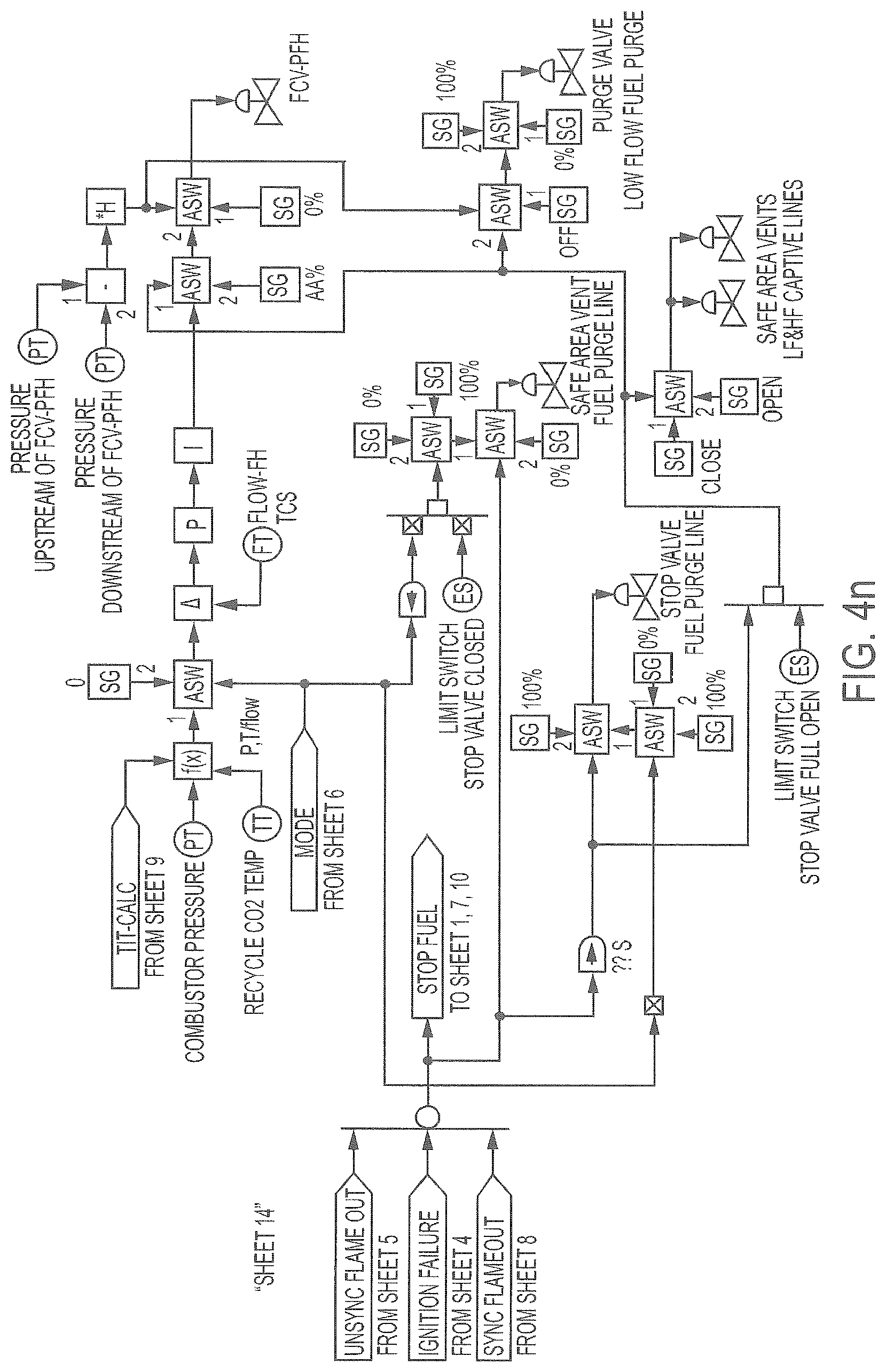
D00018

XML
uspto.report is an independent third-party trademark research tool that is not affiliated, endorsed, or sponsored by the United States Patent and Trademark Office (USPTO) or any other governmental organization. The information provided by uspto.report is based on publicly available data at the time of writing and is intended for informational purposes only.
While we strive to provide accurate and up-to-date information, we do not guarantee the accuracy, completeness, reliability, or suitability of the information displayed on this site. The use of this site is at your own risk. Any reliance you place on such information is therefore strictly at your own risk.
All official trademark data, including owner information, should be verified by visiting the official USPTO website at www.uspto.gov. This site is not intended to replace professional legal advice and should not be used as a substitute for consulting with a legal professional who is knowledgeable about trademark law.