Multi-use blood control safety catheter assembly
Harding , et al.
U.S. patent number 10,729,890 [Application Number 15/304,304] was granted by the patent office on 2020-08-04 for multi-use blood control safety catheter assembly. This patent grant is currently assigned to Becton, Dickinson and Company. The grantee listed for this patent is Becton, Dickinson and Company. Invention is credited to Stephen Bornhoft, Jon Burkholz, Ken Cluff, Weston Harding, Huibin Liu, Yiping Ma, Ralph Sonderegger, Lawrence Trainer, Weston Whitaker.


View All Diagrams
| United States Patent | 10,729,890 |
| Harding , et al. | August 4, 2020 |
Multi-use blood control safety catheter assembly
Abstract
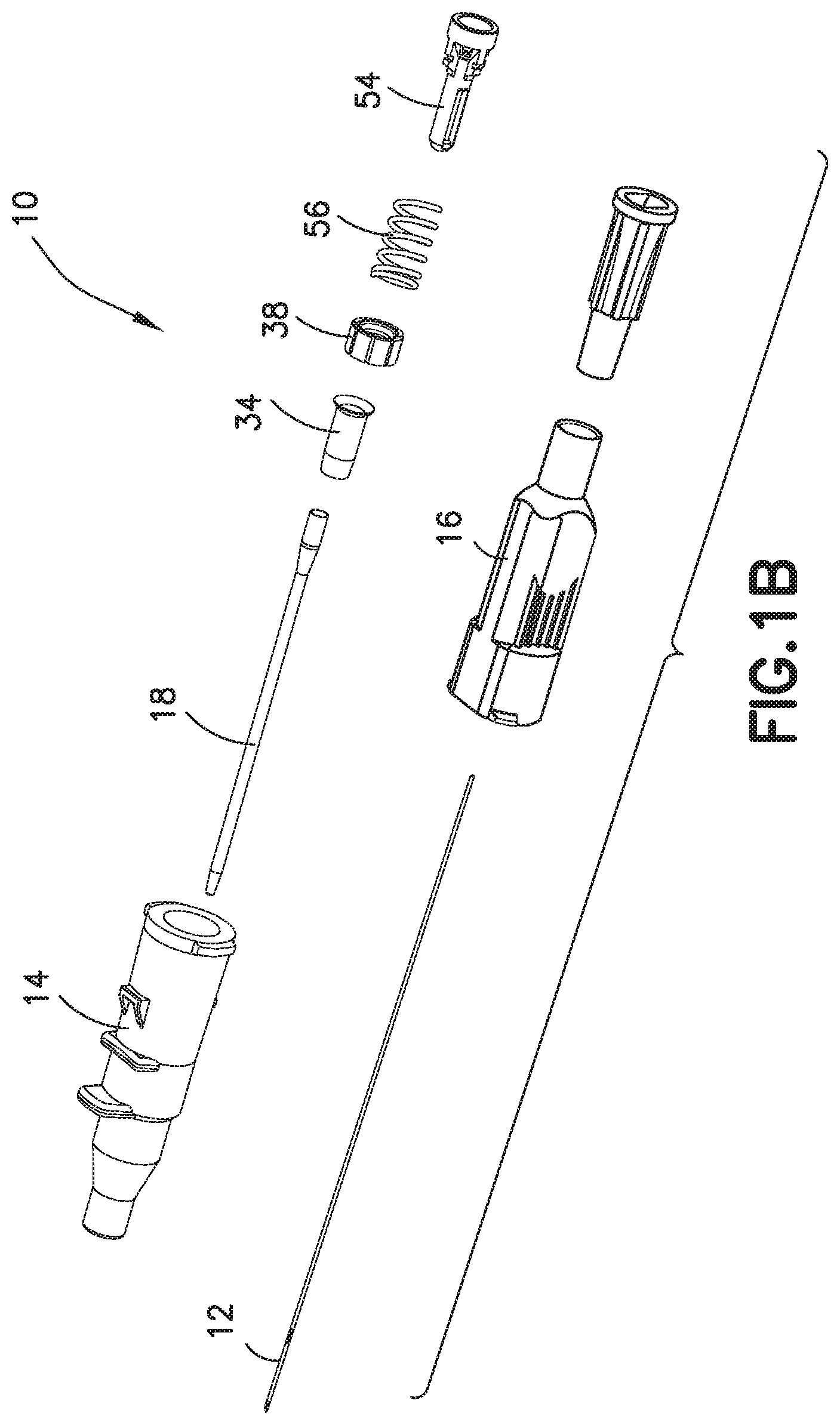
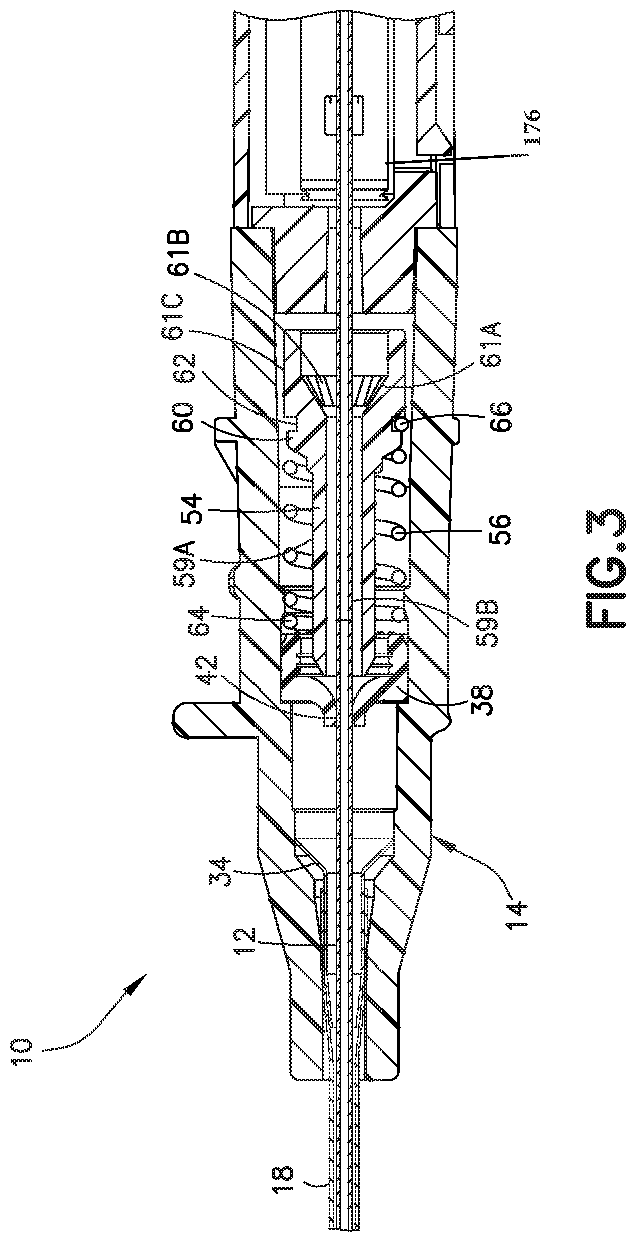
A catheter assembly comprises a catheter (18), a needle (12) having a sharp distal tip disposed within the catheter (18), a catheter hub (14) connected to the catheter (18) having the needle (12) passing therethrough, the catheter hub (14) including a valve (38) that selectively permits or blocks a flow of fluid through the catheter (18), a valve actuator (54) that moves between a first position and a second position, and a return member (56) that returns the valve actuator (54) from the second position to the first position, and a needle protection member (176) that encloses the sharp distal tip of the needle (12).
| Inventors: | Harding; Weston (Lehi, UT), Burkholz; Jon (Salt Lake City, UT), Liu; Huibin (West Jordan, UT), Cluff; Ken (Saratoga Springs, UT), Trainer; Lawrence (Murray, UT), Bornhoft; Stephen (Sandy, UT), Ma; Yiping (Layton, UT), Whitaker; Weston (Riverton, UT), Sonderegger; Ralph (Farmington, UT) | ||||||||||
|---|---|---|---|---|---|---|---|---|---|---|---|
| Applicant: |
|
||||||||||
| Assignee: | Becton, Dickinson and Company
(Franklin Lakes, NJ) |
||||||||||
| Family ID: | 1000004962278 | ||||||||||
| Appl. No.: | 15/304,304 | ||||||||||
| Filed: | April 17, 2015 | ||||||||||
| PCT Filed: | April 17, 2015 | ||||||||||
| PCT No.: | PCT/US2015/026534 | ||||||||||
| 371(c)(1),(2),(4) Date: | October 14, 2016 | ||||||||||
| PCT Pub. No.: | WO2015/161294 | ||||||||||
| PCT Pub. Date: | October 22, 2015 |
Prior Publication Data
| Document Identifier | Publication Date | |
|---|---|---|
| US 20170035992 A1 | Feb 9, 2017 | |
Related U.S. Patent Documents
| Application Number | Filing Date | Patent Number | Issue Date | ||
|---|---|---|---|---|---|
| 61981223 | Apr 18, 2014 | ||||
| 61981312 | Apr 18, 2014 | ||||
| 62077760 | Nov 10, 2014 | ||||
| Current U.S. Class: | 1/1 |
| Current CPC Class: | A61M 5/3202 (20130101); A61M 25/0631 (20130101); A61M 5/34 (20130101); A61M 25/0606 (20130101); A61M 25/0618 (20130101); A61M 39/24 (20130101); A61M 25/0097 (20130101); A61M 5/3232 (20130101); A61M 5/158 (20130101); A61M 5/3213 (20130101); A61M 2039/066 (20130101); A61M 5/3273 (20130101); A61M 2039/064 (20130101); A61M 2039/226 (20130101); A61M 2039/0673 (20130101) |
| Current International Class: | A61M 25/06 (20060101); A61M 39/24 (20060101); A61M 5/32 (20060101); A61M 5/158 (20060101); A61M 5/34 (20060101); A61M 25/00 (20060101); A61M 39/06 (20060101); A61M 39/22 (20060101) |
References Cited [Referenced By]
U.S. Patent Documents
| 3585996 | June 1971 | Reynolds et al. |
| 4332249 | June 1982 | Joslin |
| 4387879 | June 1983 | Tauschinski |
| 4482591 | November 1984 | Ward |
| 4524805 | June 1985 | Hoffman |
| 4622964 | November 1986 | Flynn |
| 4762516 | August 1988 | Luther et al. |
| 4809679 | March 1989 | Shimonaka et al. |
| 4842591 | June 1989 | Luther |
| 4850961 | July 1989 | Wanderer et al. |
| 4917668 | April 1990 | Haindl |
| 4935010 | June 1990 | Cox et al. |
| 4946133 | August 1990 | Johnson et al. |
| 4948092 | August 1990 | Kasper et al. |
| 4978344 | December 1990 | Dombrowski et al. |
| 5000740 | March 1991 | Ducharme et al. |
| 5032116 | July 1991 | Peterson et al. |
| 5053014 | October 1991 | Van Heugten |
| 5062836 | November 1991 | Wendell |
| 5085645 | February 1992 | Purdy et al. |
| 5092845 | March 1992 | Chang |
| 5108380 | April 1992 | Herlitze et al. |
| 5116021 | May 1992 | Faust et al. |
| 5135489 | August 1992 | Jepson et al. |
| 5156596 | October 1992 | Balbierz et al. |
| 5215525 | June 1993 | Sturman |
| 5215528 | June 1993 | Purdy et al. |
| 5228453 | July 1993 | Sepetka |
| 5290246 | March 1994 | Yamamoto et al. |
| 5322518 | June 1994 | Schneider et al. |
| 5328482 | July 1994 | Sircom et al. |
| 5348544 | September 1994 | Sweeney et al. |
| 5352205 | October 1994 | Dales et al. |
| 5391152 | February 1995 | Patterson |
| 5405323 | April 1995 | Rogers et al. |
| 5419766 | May 1995 | Chang et al. |
| 5423766 | June 1995 | Di Cesare |
| 5425465 | June 1995 | Healy |
| 5456675 | October 1995 | Wolbring et al. |
| 5458658 | October 1995 | Sircom |
| 5501675 | March 1996 | Erskine |
| 5520666 | May 1996 | Choudhury et al. |
| 5538508 | July 1996 | Steyn |
| 5558651 | September 1996 | Crawford et al. |
| 5575777 | November 1996 | Cover et al. |
| 5584809 | December 1996 | Gaba |
| 5596996 | January 1997 | Johanson |
| 5613663 | March 1997 | Schmidt et al. |
| 5697907 | December 1997 | Gaba |
| 5718688 | February 1998 | Wozencroft |
| 5749861 | May 1998 | Guala et al. |
| 5772636 | June 1998 | Brimhall et al. |
| 5817069 | October 1998 | Arnett |
| 5851196 | December 1998 | Arnett |
| 5858002 | January 1999 | Jesch |
| 5911710 | June 1999 | Barry et al. |
| 5951515 | September 1999 | Osterlind |
| 5954698 | September 1999 | Pike |
| 5967490 | October 1999 | Pike |
| 6001080 | December 1999 | Kuracina et al. |
| 6042876 | March 2000 | Deem |
| 6117108 | September 2000 | Woehr et al. |
| 6213978 | April 2001 | Voyten |
| 6221047 | April 2001 | Greene et al. |
| 6224569 | May 2001 | Brimhall et al. |
| 6379333 | April 2002 | Brimhall et al. |
| 6425884 | July 2002 | Wemmert et al. |
| 6506181 | January 2003 | Meng et al. |
| 6595981 | July 2003 | Huet |
| 6616630 | September 2003 | Woehr et al. |
| 6652486 | November 2003 | Bialecki et al. |
| 6709419 | March 2004 | Woehr |
| 6749588 | June 2004 | Howell et al. |
| 6972002 | December 2005 | Thorne |
| RE38996 | February 2006 | Crawford et al. |
| 7008404 | March 2006 | Nakajima |
| 7226434 | June 2007 | Carlyon et al. |
| 7470254 | December 2008 | Basta et al. |
| 7530965 | May 2009 | Villa et al. |
| 7597681 | October 2009 | Sutton et al. |
| 7651476 | January 2010 | Kohler |
| 7682340 | March 2010 | Funamura et al. |
| 7736332 | June 2010 | Carlyon et al. |
| 7736339 | June 2010 | Woehr |
| 7947018 | May 2011 | McKinnon |
| 7988664 | August 2011 | Fiser et al. |
| 8308691 | November 2012 | Woehr et al. |
| 8328762 | December 2012 | Woehr et al. |
| 8333735 | December 2012 | Woehr et al. |
| 8337463 | December 2012 | Woehr et al. |
| 8348893 | January 2013 | Carlyon |
| 8357119 | January 2013 | Stout et al. |
| 8361020 | January 2013 | Stout |
| 8361038 | January 2013 | McKinnon et al. |
| 8366684 | February 2013 | Harding |
| 8382718 | February 2013 | Woehr |
| 8388583 | March 2013 | Stout et al. |
| 8419688 | April 2013 | Woehr et al. |
| 8460247 | June 2013 | Woehr et al. |
| 8469928 | June 2013 | Stout et al. |
| 8496623 | July 2013 | Burkholz |
| 8540728 | September 2013 | Woehr et al. |
| 8591467 | November 2013 | Walker et al. |
| 8591468 | November 2013 | Woehr et al. |
| 8597249 | December 2013 | Woehr et al. |
| 8764711 | July 2014 | Kuracina et al. |
| 8827965 | September 2014 | Woehr et al. |
| 8864715 | October 2014 | Cluff et al. |
| 8926564 | January 2015 | King et al. |
| 8939938 | January 2015 | Funamura et al. |
| 8951230 | February 2015 | Tanabe et al. |
| 9056188 | June 2015 | Hager et al. |
| 9089671 | July 2015 | Stout et al. |
| 9095679 | August 2015 | Nishimura et al. |
| 9101748 | August 2015 | Harding et al. |
| 9101749 | August 2015 | Nakagami et al. |
| 9114241 | August 2015 | Stout et al. |
| 9149625 | October 2015 | Woehr et al. |
| 9149626 | October 2015 | Woehr et al. |
| 8932259 | November 2015 | Stout et al. |
| 9370641 | June 2016 | Woehr et al. |
| 9408632 | August 2016 | Erskine |
| 9592152 | March 2017 | Griffis et al. |
| 9717886 | August 2017 | Kuehn et al. |
| 2001/0053895 | December 2001 | Vaillancourt |
| 2002/0128604 | September 2002 | Nakajima |
| 2002/0169418 | November 2002 | Menzi et al. |
| 2003/0195471 | October 2003 | Woehr et al. |
| 2004/0116856 | June 2004 | Woehr et al. |
| 2004/0204689 | October 2004 | Lynn |
| 2004/0225260 | November 2004 | Villa et al. |
| 2005/0010176 | January 2005 | Dikeman et al. |
| 2005/0043684 | February 2005 | Basta et al. |
| 2005/0075609 | April 2005 | Latona |
| 2005/0113755 | May 2005 | Greene et al. |
| 2006/0074384 | April 2006 | Kohler |
| 2006/0155245 | July 2006 | Woehr |
| 2006/0178635 | August 2006 | Callaway |
| 2006/0200080 | September 2006 | Abulhaj |
| 2007/0038186 | February 2007 | Sutton et al. |
| 2007/0129689 | June 2007 | Woehr et al. |
| 2007/0176414 | August 2007 | McBee et al. |
| 2007/0270754 | November 2007 | Soderholm et al. |
| 2008/0097343 | April 2008 | Woehr |
| 2008/0140011 | June 2008 | Hager et al. |
| 2008/0208132 | August 2008 | Funamura et al. |
| 2008/0243086 | October 2008 | Hager et al. |
| 2009/0137958 | May 2009 | Erskine |
| 2009/0182280 | July 2009 | Glowacki et al. |
| 2009/0312711 | December 2009 | Brimhall |
| 2010/0137803 | June 2010 | Funamura et al. |
| 2010/0191189 | July 2010 | Harding et al. |
| 2010/0217208 | August 2010 | Snow |
| 2011/0060286 | March 2011 | Tanabe et al. |
| 2011/0160662 | June 2011 | Stout |
| 2011/0288482 | November 2011 | Farrell et al. |
| 2011/0301551 | December 2011 | Koehler et al. |
| 2012/0078200 | March 2012 | Woehr et al. |
| 2012/0123354 | May 2012 | Woehr |
| 2012/0136311 | May 2012 | Knutsson et al. |
| 2012/0220957 | August 2012 | Kuracina et al. |
| 2012/0238966 | September 2012 | Kuracina et al. |
| 2012/0277679 | November 2012 | Steube |
| 2013/0090607 | April 2013 | McKinnon et al. |
| 2013/0090609 | April 2013 | Sonderegger et al. |
| 2013/0178807 | July 2013 | Baid |
| 2013/0184645 | July 2013 | Baid |
| 2013/0226141 | August 2013 | King et al. |
| 2013/0245567 | September 2013 | Tremblay |
| 2013/0253443 | September 2013 | Woehr et al. |
| 2013/0324930 | December 2013 | Fuchs et al. |
| 2014/0012203 | January 2014 | Woehr et al. |
| 2014/0018738 | January 2014 | Steube |
| 2014/0058329 | February 2014 | Walker et al. |
| 2014/0074034 | March 2014 | Tanabe et al. |
| 2014/0276434 | September 2014 | Woehr et al. |
| 2014/0303561 | October 2014 | Li |
| 2014/0364809 | December 2014 | Isaacson et al. |
| 2015/0151088 | June 2015 | Lim |
| 2016/0008580 | January 2016 | Woehr et al. |
| 2016/0106959 | April 2016 | Woehr |
| 2016/0114137 | April 2016 | Woehr et al. |
| 2016/0158503 | June 2016 | Woehr |
| 2016/0158526 | June 2016 | Woehr |
| 2006203664 | Feb 2008 | AU | |||
| 2133053 | Mar 1993 | CA | |||
| 1871043 | Nov 2006 | CN | |||
| 202682467 | Jan 2013 | CN | |||
| 106470607 | Mar 2017 | CN | |||
| 0352928 | Jan 1990 | EP | |||
| 2228093 | Sep 2010 | EP | |||
| 2343095 | Jul 2011 | EP | |||
| 2489393 | Aug 2012 | EP | |||
| 2566543 | Mar 2013 | EP | |||
| H1057497 | Mar 1998 | JP | |||
| 2001-514943 | Sep 2001 | JP | |||
| 2002126080 | May 2002 | JP | |||
| 2002263197 | Sep 2002 | JP | |||
| 2008-173206 | Jul 2008 | JP | |||
| 2010099534 | May 2010 | JP | |||
| 2011-115630 | Jun 2011 | JP | |||
| 3170612 | Aug 2011 | JP | |||
| 2012-517326 | Aug 2012 | JP | |||
| 2013-192868 | Sep 2013 | JP | |||
| 173383 | Aug 2011 | SG | |||
| WO-1993005840 | Apr 1993 | WO | |||
| WO-1995022364 | Aug 1995 | WO | |||
| WO-9934849 | Jul 1999 | WO | |||
| WO-2001012249 | Feb 2001 | WO | |||
| 0193940 | Dec 2001 | WO | |||
| 0195958 | Dec 2001 | WO | |||
| WO-2003011381 | Feb 2003 | WO | |||
| WO-2004004819 | Jan 2004 | WO | |||
| WO-2005/042073 | May 2005 | WO | |||
| 2008064332 | May 2008 | WO | |||
| WO-2012020633 | Feb 2012 | WO | |||
| WO-2013/014639 | Jan 2013 | WO | |||
| WO-2013/051242 | Apr 2013 | WO | |||
| WO-2013052666 | Apr 2013 | WO | |||
| WO-2013137348 | Sep 2013 | WO | |||
| WO-2014/054166 | Apr 2014 | WO | |||
| WO-2014126865 | Aug 2014 | WO | |||
Other References
|
Sep. 8, 2015, Written Opinion of the International Searching Authority for related application No. PCT/US15/26534. cited by applicant . Sep. 8, 2015, International Search Report for related application No. PCT/US15/26534. cited by applicant . Medikit Co.,Ltd., Dual Protection Safety I.V. Catheter--Supercath 5: A New Generation of Safety I.V. Catheter, Medikit, Manufacturer Togo Medikit Co., Ltd., IVBB080001-B61G2S, Approximately 2008 (3 Pages Total). cited by applicant . US 5,755,409, 8/1979, Sigmund (withdrawn) cited by applicant . Singapore Office Action dated Nov. 12, 2019 in Singapore Patent Application No. 11201708371S. cited by applicant . Brazilian Office Action dated Feb. 4, 2020 in Brazilian Patent Application No. 112015030658-6. cited by applicant . Singapore Office Action dated Jan. 29, 2020 in Singapore Patent Application No. 11201706370P. cited by applicant . Japanese Office Action dated Jan. 28, 2020 in Japanese Patent Application No. 2017-554341. cited by applicant. |
Primary Examiner: Hall; Deanna K
Attorney, Agent or Firm: Dickinson Wright PLLC
Parent Case Text
RELATED APPLICATIONS
This application claims the benefit under 35 U.S.C. .sctn. 119(e) of U.S. Provisional Patent Application Ser. 61/981,223, filed on Apr. 18, 2014, U.S. Provisional Application 61/981,312, filed on Apr. 18, 2014, and U.S. Provisional Patent Application Ser. No. 62/077,760, filed on Nov. 10, 2014. Each of these applications is hereby incorporated by reference in its entirety.
Claims
The invention claimed is:
1. A catheter assembly comprising: a catheter; a needle having a sharp distal tip disposed within the catheter; a catheter hub connected to the catheter having the needle passing therethrough, the catheter hub including: a valve that selectively permits or blocks a flow of fluid through the catheter; a valve actuator that moves between a first position and a second position to actuate the valve, the valve actuator including a central flow passage and one or more external grooves or side openings to promote flushing; a return member comprising a coil spring that returns the valve actuator from the second position to the first position; and a needle protection member that encloses the sharp distal tip of the needle.
2. The catheter assembly of claim 1, wherein the coil spring supports the valve actuator so that the valve actuator is held in the catheter hub and does not contact an inner wall of the catheter hub.
3. The catheter assembly of claim 1, wherein the needle protection member encloses the needle completely.
4. The catheter assembly of claim 1, wherein the needle protection member includes a second spring to retract the needle.
5. The catheter assembly of claim 1, wherein the needle protection member encloses only a sharp distal tip area of the needle.
6. The catheter assembly of claim 5, wherein: the needle further includes a deformation, and the needle protection member interacts with the deformation.
7. The catheter assembly of claim 1, wherein the needle protection member includes a resilient clip.
8. The catheter assembly of claim 7, wherein the needle biases the resilient clip into an open position during needle use.
9. The catheter assembly of claim 7, wherein the resilient clip moves to a closed position to block the distal tip of the needle when the needle is retracted after use.
10. The catheter assembly of claim 9, wherein when the resilient clip is in the closed position, the resilient clip prevents the distal tip of the needle from exiting the resilient clip.
11. The catheter assembly of claim 9, wherein the resilient clip further includes at least one barrier that blocks the needle in the closed position.
12. The catheter assembly of claim 1, wherein the valve comprises a septum.
13. The catheter assembly of claim 12, wherein the valve actuator moves between the first position that is adjacent to the septum and the second position that opens one or more pre-formed slits in the septum.
14. A catheter assembly comprising: a catheter; and a catheter hub connected to the catheter, the catheter hub including: a valve that selectively permits or blocks a flow of fluid through the catheter; and a valve actuator that moves between a first position and a second position, the valve actuator including a central flow passage, one or more side openings disposed centrally on the valve actuator, and one or more external grooves that extend axially along a distal portion of the valve actuator, at least portions of the one or more external grooves not being in direct fluid communication with the central flow passage.
15. The catheter assembly of claim 14, wherein in the second position, the valve actuator and the one or more grooves of the valve actuator penetrate the valve.
16. The catheter assembly of claim 15, wherein when the valve actuator penetrates the valve, the one or more side openings do not penetrate the valve.
17. The catheter assembly of claim 15, wherein when the valve actuator penetrates the valve, the one or more external grooves prevent sealing between the septum and the valve actuator.
18. The catheter assembly of claim 14, wherein the valve comprises a septum.
19. The catheter assembly of claim 18, wherein the valve actuator moves between the first position that is adjacent to the septum and the second position that penetrates one or more pre-formed slits in the septum.
20. The catheter assembly of claim 14, further comprising a return member that returns the valve actuator from the second position to the first position.
21. The catheter assembly of claim 14, wherein the external grooves extend longitudinally from a distal end of the valve actuator to a position adjacent to a proximal end of the valve actuator.
22. The catheter assembly of claim 14, wherein the external grooves extend longitudinally from a distal end of the valve actuator to a position beyond the one or more side openings of the valve actuator.
23. A method of operating a catheter assembly comprising: disposing a needle having a sharp distal tip within a catheter in a position configured to receive fluid; removing the needle while maintaining fluid flow through the catheter; enclosing at least the sharp distal tip of the needle by a needle protection member; opening a valve with a valve actuator that moves from a first position to a second position to establish fluid communication between the catheter and a catheter hub, the valve actuator including a central flow passage and one or more external grooves or side openings; directing fluid through the central flow passage and through the one or more external grooves or side openings of the valve actuator; and using a coil spring to return the valve actuator from the second position to the first position to close the valve.
24. The method of operating the catheter assembly of claim 23, further comprising: biasing the needle protection member by the needle into an open position during use; and moving the needle protection member to block the distal tip of the needle when the needle is retracted after use, wherein the needle protection member comprises a resilient clip.
25. The method of operating the catheter assembly of claim 23, further comprising: penetrating the valve by moving the valve actuator from the first position to the second position and through the valve.
26. The catheter assembly of claim 23, wherein the valve comprises a septum.
27. The catheter assembly of claim 26, wherein the valve actuator moves between the first position that is adjacent to the septum and the second position that opens one or more pre-formed slits in the septum.
28. A catheter assembly comprising: a catheter; a needle having a sharp distal tip disposed within the catheter; and a catheter hub connected to the catheter having the needle passing therethrough, the catheter hub including: a valve that selectively permits or blocks a flow of fluid through the catheter; a valve actuator that moves between a first position and a second position to actuate the valve, the valve actuator including a central flow passage and one or more external grooves or side openings to promote flushing; and a spring that returns the valve actuator from the second position to the first position, the spring being in contact with the valve during said return; wherein the spring supports the valve actuator so that the valve actuator is held in the catheter hub and does not contact an inner wall of the catheter hub.
29. The catheter assembly of claim 28, wherein the spring comprises a coil spring that surrounds the valve actuator.
30. The catheter assembly of claim 28, wherein: the spring includes an outer diameter; the catheter hub includes an inner surface; and the outer diameter of the spring and the inner surface of the catheter hub are engaged via an interference fit.
31. The catheter assembly of claim 28, wherein the valve actuator is supported only by the spring.
32. The catheter assembly of claim 28, wherein the spring includes an inner diameter; the valve actuator includes an outer surface; and the inner diameter of the spring and the outer surface of the valve actuator are engaged via an interference fit.
Description
FIELD
Various exemplary embodiments of the invention relate to catheter assemblies.
BACKGROUND
Catheter assemblies are used to place a catheter properly into the vascular system of a patient. Once in place, catheters such as intravenous catheters may be used to infuse fluids including normal saline, medicinal compounds, and/or nutritional compositions into a patient in need of such treatment. Catheters additionally enable the removal of fluids from the circulatory system and monitoring of conditions within the vascular system of the patient.
SUMMARY OF THE INVENTION
It is an aspect of the present invention to provide a catheter assembly in which a septum and a septum actuator provide a multi-use function for blood control, for example, in combination with a return member that allows for engagement and disengagement of the septum actuator to the septum, and where at least a portion of an introducer needle is protected after use. For example, the needle protection can enclose a distal needle tip, a distal needle tip and a needle deformation, or the complete needle. Additionally, the septum actuator can include one or more external grooves that extend axially along a distal portion of the septum actuator.
The foregoing and/or other aspects of the present invention can be achieved by providing a catheter assembly comprising a catheter, a needle having a sharp distal tip disposed within the catheter, a catheter hub connected to the catheter having the needle passing therethrough, the catheter hub including a valve that selectively permits or blocks a flow of fluid through the catheter, a valve actuator that moves between a first position and a second position, and a return member that returns the valve actuator from the second position to the first position, and a needle protection member that encloses the sharp distal tip of the needle.
The foregoing and/or other aspects of the present invention can further be achieved by providing a catheter assembly comprising a catheter, and a catheter hub connected to the catheter, the catheter hub including a valve that selectively permits or blocks a flow of fluid through the catheter, a valve actuator that moves between a first position and a second position, the valve actuator including one or more external grooves that extend axially along a distal portion of the valve actuator, and a return member that returns the valve actuator from the second position to the first position.
The foregoing and/or other aspects of the present invention can also be achieved by a method of operating a catheter assembly comprising disposing a needle having a sharp distal tip within a catheter in a position configured to receive fluid, removing the needle while maintaining fluid flow through the catheter, enclosing at least the sharp distal tip of the needle by a needle protection member, opening a valve with a valve actuator that moves from a first position to a second position to establish fluid communication between the catheter and a catheter hub, and returning the valve actuator from the second position to the first position to block fluid communication between the catheter and the catheter hub.
Additional and/or other aspects and advantages of the present invention will be set forth in the description that follows, or will be apparent from the description, or may be learned by practice of the invention.
BRIEF DESCRIPTION OF THE DRAWINGS
The above aspects and features of the present invention will be more apparent from the description for the exemplary embodiments of the present invention taken with reference to the accompanying drawings, in which:
FIG. 1A is a perspective view of an exemplary catheter assembly;
FIG. 1B is an exploded perspective view of the catheter assembly of FIG. 1A;
FIG. 2A is a sectional, side view of an exemplary catheter hub and actuator;
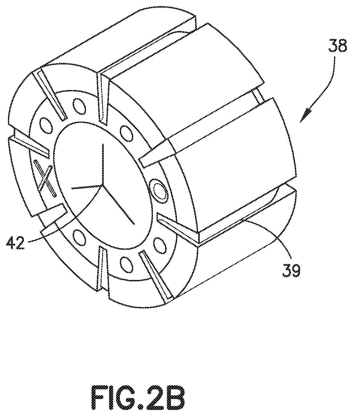
FIG. 2B is a perspective view of an exemplary septum;
FIG. 3 is a sectional, side view of an exemplary catheter hub, actuator, and spring with an introducer needle inserted through the catheter hub;
FIG. 4 is a sectional side view of the catheter hub of FIG. 3 with the introducer needle removed;
FIG. 5 is a sectional, side view of the catheter hub of FIG. 4 with a Luer connector inserted;
FIG. 6 is a sectional, side view of the catheter hub of FIG. 5 with the Luer connector pushing the actuator through the septum;
FIG. 7 is a sectional, side view of the catheter hub of FIG. 6 with the Luer connector being removed;
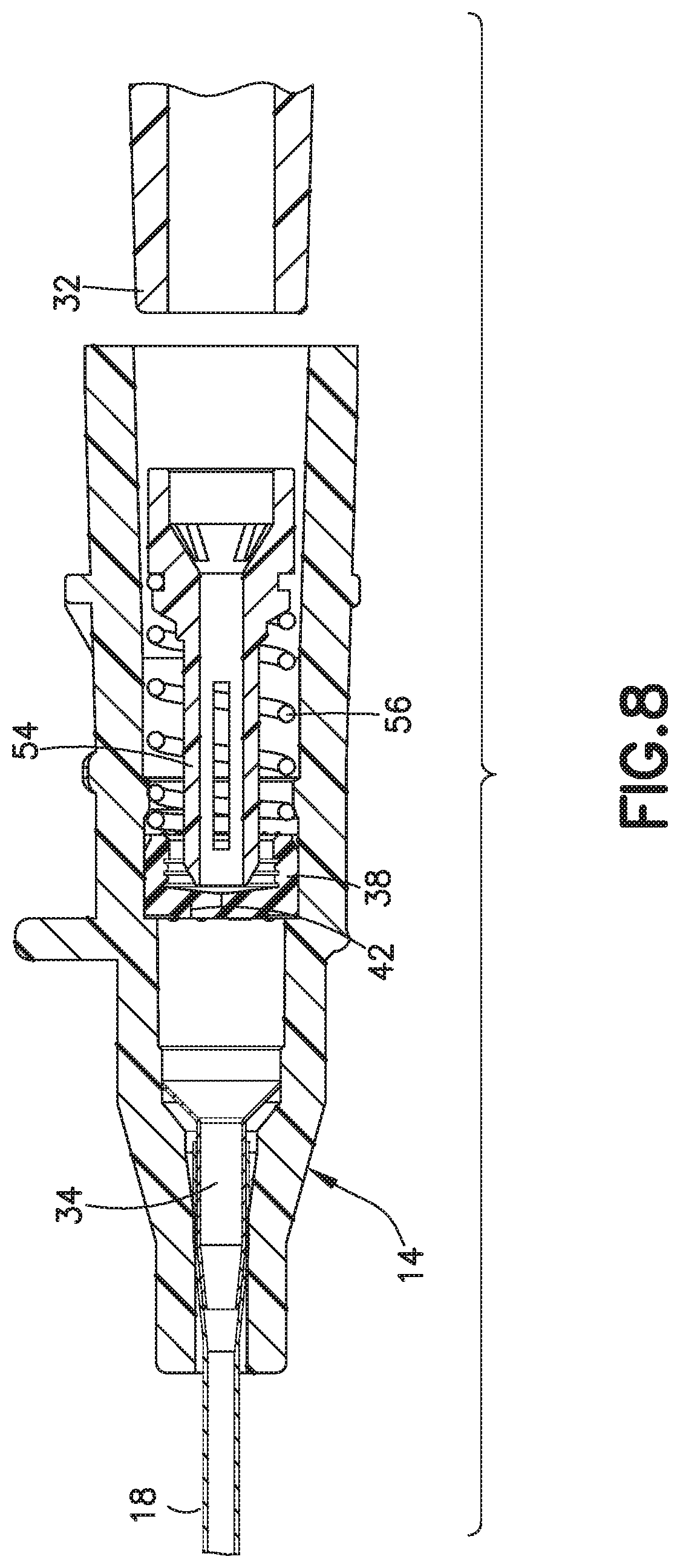
FIG. 8 is a sectional, side view of the catheter hub of FIG. 7 with the Luer connector removed;
FIG. 9 is a sectional, side view of another exemplary embodiment of a catheter with an actuator and biasing member;
FIG. 10 is a sectional, side view of another exemplary embodiment of a catheter with an actuator and biasing member;
FIG. 11 illustrates a sectional, side view of another exemplary embodiment of a catheter with an actuator and biasing member;
FIG. 12 illustrates a sectional, side view of another exemplary embodiment of a catheter with an actuator and biasing member;
FIG. 13 illustrates a sectional, side view of another exemplary embodiment of a catheter with an actuator and biasing member;
FIG. 14 illustrates a sectional, isometric view of another exemplary embodiment of a catheter with an actuator and biasing member;
FIG. 15A illustrates a sectional, side view of another exemplary embodiment of a catheter with an actuator and biasing member;
FIG. 15B is a sectional, side view of the catheter of FIG. 15A with a Luer connector inserted;
FIG. 16 illustrates a sectional, side view of another exemplary embodiment of a catheter with an actuator and biasing member;
FIG. 17 illustrates a sectional, perspective view of another exemplary embodiment of a catheter with an actuator and biasing member;
FIG. 18 illustrates a sectional, side view of another exemplary embodiment of a catheter with an actuator and biasing member;
FIG. 19A illustrates a sectional, side view of another exemplary embodiment of a catheter with an actuator and biasing member;
FIG. 19B is a sectional, side view of the catheter of FIG. 19A pushed through the septum;
FIG. 20A illustrates a sectional, side view of another exemplary embodiment of a catheter with an actuator and biasing member;
FIG. 20B is the catheter of FIG. 20A with a Luer connector inserted;
FIG. 21A illustrates a sectional, side view of another exemplary embodiment of a catheter with an actuator and biasing member and a Luer connector inserted;
FIG. 21B is a front view depiction of the septum of FIG. 21A;
FIG. 21C is a sectional, side view depiction of the actuator of 21A with an elastomer molded to the tip of the actuator;
FIG. 22 is a perspective view of a side-port catheter;
FIG. 23 illustrates a sectional, side view of an exemplary embodiment of catheter with an actuator and a biasing member for a side-port catheter;
FIG. 24 illustrates a sectional, side view of another exemplary embodiment of catheter with an actuator and a biasing member for a side-port catheter;
FIG. 25 illustrates a sectional, side view of another exemplary embodiment of catheter with an actuator and a biasing member for a side-port catheter;
FIG. 26 illustrates a sectional, side view of another exemplary embodiment of catheter with an actuator and a biasing member for a side-port catheter;
FIG. 27 is a sectional, side view of an exemplary catheter assembly having a needle tip shield;
FIG. 28 is a perspective view of an exemplary outer sleeve of the needle tip shield;
FIG. 29 is a side view of the outer sleeve of FIG. 28;
FIG. 30 is a top view of the outer sleeve of FIG. 28;
FIG. 31 is a top perspective view of an exemplary inner sleeve of the needle tip shield;
FIG. 32 is a bottom perspective view of the inner sleeve of FIG. 31;
FIG. 33 is a top perspective view of a needle tip shield clip;
FIG. 34 is a side view of the clip of FIG. 33;
FIG. 35 is a sectional, side view of the needle tip shield of FIG. 27;
FIG. 36 is another sectional, side view of the needle tip shield of FIG. 27;
FIG. 37 is a sectional, side view of the needle tip shield with the clip in a closed position;
FIG. 38 illustrates a right side view of another exemplary embodiment of an actuator;
FIG. 39A illustrates a sectional view of the actuator of FIG. 38 in a catheter hub assembly;
FIG. 39B illustrates a sectional view of the catheter hub assembly of FIG. 39A when penetrating a septum;
FIG. 39C illustrates a left perspective sectional view of the catheter hub assembly of FIG. 39A when penetrating a septum;
FIG. 40A illustrates a sectional view of another exemplary embodiment of a catheter hub assembly;
FIG. 40B illustrates a sectional view of the catheter hub assembly of FIG. 40A when penetrating a septum;
FIG. 40C illustrates a left perspective sectional view of the catheter hub assembly of FIG. 40A when penetrating a septum;
FIG. 41 illustrates a sectional view of another exemplary embodiment of a catheter assembly in the needle extended position;
FIG. 42 illustrates a sectional view of the catheter assembly of FIG. 41 in the needle retracted position;
FIG. 43 illustrates a sectional view of another exemplary embodiment of a catheter assembly in the needle extended position;
FIG. 44 illustrates a sectional view of the catheter assembly of FIG. 43 in the needle retracted position;
FIG. 45 illustrates a sectional view of the catheter hub assembly and the needle hub assembly of FIG. 44;
FIG. 46 illustrates a sectional view of another exemplary embodiment of a catheter assembly in the needle extended position;
FIG. 47 illustrates a sectional view of the catheter hub assembly and the needle hub assembly of FIG. 46 in the needle retracted position;
FIG. 48 illustrates a bottom plan view of the catheter hub assembly and the needle hub assembly of FIG. 46 in the needle retracted position;
FIG. 49 illustrates an exemplary embodiment of a blood flashback feature of a catheter assembly;
FIG. 50 illustrates a needle in the catheter assembly of FIG. 49; and
FIG. 51 illustrates another exemplary embodiment of a blood flashback feature of a catheter assembly.
DETAILED DESCRIPTION OF EXEMPLARY EMBODIMENTS
A catheter assembly 10, as shown in FIGS. 1A and 1B, includes a hollow introducer needle 12, a catheter hub 14, and a needle hub 16. The introducer needle 12 has a sharpened distal end and extends through the catheter hub 14. A flexible catheter tube 18 extends from the distal end of the catheter hub 14, with the needle 12 passing through the catheter tube 18. Initially, the needle 12 is inserted into a patient's vein. The catheter tube 18 is pushed along the needle 12 and into the vein following the needle 12. After the catheter tube 18 is inserted, the needle 12 is removed from the patient's vein and the catheter hub 14, leaving the catheter tube 18 in the patient as the needle 12 is discarded.
According to various exemplary embodiments, the catheter hub 14 has a distal end 20, a proximal end 22, an inner surface 24, and an outer surface 26. The distal end 20 includes a catheter opening and the proximal end includes a Luer connector opening. The inner surface 24 surrounds a channel 28 that permits fluid passage through the catheter hub 14. The outer surface 26 includes one or more projections 30 to secure a Luer connector 32 (FIG. 4) to the catheter hub 14. The projections 30 may form a threaded connection with the Luer connector 32 or they may connect to the Luer connector 32 through a snap fit or other twisting connection. One example of a standard connection is a LUER-LOK.RTM. connection. Certain types of Luer connectors 32 utilize a slip fit into the catheter hub 14. The catheter hub 14 may be made from a polymer material that is transparent or semi-transparent so that fluid flow through the catheter hub may be observed by a user or it may be made from an opaque material.
The flexible catheter tube 18 extends through the catheter opening. A metal wedge 34 may be positioned in the channel to secure the catheter tube 18 in the catheter opening. The wedge 34 has a first end engaging the catheter tube 18 and a second end engaging the inner surface 24 of the catheter hub 14. The first end of the wedge 34 has a tapered nose that allows it to easily engage the catheter tube 18. As the wedge 34 is inserted into the catheter tube 18, the catheter tube 18 expands, creating an interference fit between the catheter tube 18, the wedge 34, and the inner surface 24 of the catheter hub 14. The second end of the wedge 34 has a substantially frusto-conical shaped portion with an outer edge that engages the inner surface 24 of the catheter hub 14. A wedge flange 36 may be formed on the inner surface 24 to create a limit for distal movement of the wedge 34. A similar shoulder, tab, or groove may limit the distal movement of the wedge 34.
A pre-slit resilient septum 38 is positioned in the channel 28 and functions as a valve that forms a fluid-tight seal and selectively admits fluid to or from the flexible catheter tube 18. In other words, the valve selectively permits or blocks the flow of fluid through the flexible catheter tube 18. The septum 38 may be seated against a septum flange 40 to limit distal movement. Protrusions or other internal structure may form an interference fit with the septum 38 to retain it in place or limit its proximal movement. As best shown in FIG. 2B, the septum 38 has one or more pre-formed openings or slits 42 designed to selectively prevent unwanted fluid flow through the septum 38. The septum 38 preferably has three intersecting slits 42 forming three flaps that open when engaged by a valve actuator or a septum actuator (hereinafter actuator).
The septum 38 further includes a plurality of axial flow channels 39. The flow channels 39 are disposed on an outer circumference of the septum 38. Eight flow channels 39 equidistant from each other are illustrated, although various quantities and positions are contemplated. The flow channels 39 have an appropriate width and depth so that when the septum 38 is not opened, blood can enter and air can escape the space distal of the septum 38 in the front portion of the catheter hub 14. At the same time, the flow channels 39 are sized small enough to prevent the blood from exiting past the septum 38 (at least for some period of time). Such a configuration is possible because the intermolecular forces in the blood are greater than the intermolecular forces in air.
The septum 38 shown in FIG. 2B may be used in any of the embodiments discussed herein. Other septum configurations may be used as would be understood by one of ordinary skill in the art. When the catheter tube 18 is initially inserted into a patient, and the introducer needle 12 is removed, the septum 38 prevents blood from flowing through the channel 28 and out of the distal end. The septum 38 is made of an elastic material to form the valve, for example silicone rubber. Other elastic materials may be used and non-elastic materials may be incorporated in the septum 38 as needed.
FIG. 2A depicts an exemplary embodiment of an actuator 44 having an actuator barrel 46 surrounding an internal passage 46A. Actuators similar to that of FIG. 2A may be used in any of the embodiments described herein. The actuator 44 is positioned in the channel 28 and is axially moveable in the channel 28 to engage and open the slits 42. The actuator barrel 46 is a substantially tubular member and the internal passage 46A is substantially cylindrical to allow fluid to flow through the actuator 44 and through the septum 38 when the septum 38 is opened or penetrated by the actuator 44. The tubular member has a distal opening 46B, one or more side openings 46C, and a distal end 46D that engages and opens the slits 42. The side openings 46C of the actuator 44 allow for fluid flushing.
A conical section 48 forms the proximal end of the actuator 44. The conical section 48 is a substantially frusto-conical member that is tapered towards the actuator barrel 46 and has one or more proximal openings 48A to permit fluid flow. The conical section 48 receives or engages or abuts the end of a Luer connector (not shown). One or more tabs 50 extend from the actuator 44 to engage a respective flange 52 or one or more shoulders on the inner surface 24 of the catheter hub 14. The interaction between the tabs 50 and the flange 52 limits proximal movement of the actuator 44. The proximal opening 48A and an internal passage 48B communicating with the internal passage 46A preferably allow fluid to flow between the Luer connector and the catheter tube 18. Side openings 48C in the conical section 48 allow for fluid flushing. The actuator 44 is preferably made in one piece from a rigid or semi-rigid material, for example a rigid polymer material or a metal.
As a male Luer connector is inserted in the catheter hub 14, the end of the Luer connector slides toward the conical section 48 and abuts the actuator 44. Further movement of the Luer connector moves the actuator 44 axially toward and through the septum 38 with the distal end 46D of the actuator barrel 46 separating the one or more slits 42 to engage and open the septum 38. After the septum 38 is opened by the actuator 44, fluid is permitted to flow from the Luer connector, through the internal passages 48B and 48D of the actuator 44, and into the flexible catheter 18 or vice versa. When the Luer connector 32 is removed, the actuator barrel 46 remains in the septum 38.
FIGS. 3-8 depict an embodiment of the catheter assembly 10 that includes a return member 56 which provides a multi-use function for blood control, for example. The actuator 54 has an actuator barrel 59A surrounding an internal passage 59B. The actuator barrel 59A is a substantially tubular member and the internal passage 59B is substantially cylindrical. The tubular member has one or more openings 55 to permit fluid flow through and around the actuator barrel 59A. The openings 55 advantageously provide increased area for the fluid to move inside the catheter hub assembly. The increased area advantageously allows for fluid flushing and to prevent coagulation of fluid in the proximal and distal ends of the septum 38. Additionally, the openings 55 advantageously minimize the stagnation of fluid and allow for greater mixing.
A first end of the actuator barrel has a nose 58 with a chamfered outer surface to engage the septum 38. A frusto-conical section 61A extends from the second end of the actuator barrel 59A. The frusto-conical section 61A has one or more openings 61B to permit fluid flow therethrough. A cylindrical section 61C extends from the frusto-conical section 61A to engage a male Luer connector 32. One or more hooks 60 having an angled front surface and a slot 62 extend from the actuator barrel 59A.
In the exemplary embodiment shown in FIGS. 3-8, the return member 56 is a biasing member such as a coil spring, for example a helical compression spring with a distal end 64 and a proximal end 66. The spring can be, but is not limited to, rubber, silicone rubber, a thermal plastic, a thermal plastic elastomer, metal, plastic, an elastomeric member such as an elastomer, or another suitable resilient material. The distal end 64 of the spring forms an interference fit with the inner surface 24 of the catheter hub 14. The interference fit may be sufficient to retain the spring, even during loading, or the distal end 64 of the spring may also abut the septum 38. The proximal end 66 of the spring connects to the actuator 54, for example by fitting over the hook 60 and into the slot 62.
In other various embodiments, the actuator 54 and the biasing member 56 are combined to be a unitary structure. In various exemplary embodiments, the inner surface 24 of the catheter hub 14 and/or the outer surface of the actuator 54 and/or biasing member 56 includes undercuts, bumps, projections, tines, or other suitable structure to form a snap connection between the catheter hub 14 and the biasing member 56, and the biasing member 56 and the actuator 54. In further various exemplary embodiments, the biasing member or spring 56 and actuator 54 may be attached to each other via an engagement that does not require a snap connection including a diametric interference fit or a press fit.
FIGS. 3-7 depict the operation of the catheter hub 14 having an actuator 54 and a return member such as a biasing member or spring 56. The return member functions by returning the actuator 54 from a second position engaging the septum 38 (opening or penetrating the septum, for example) to open the valve, to a first position at a proximal end of the septum 38 (not engaging the septum 38) to close the valve. The needle 12 initially extends through the actuator 54, the septum 38, the wedge 34, and the catheter tube 18. After the needle 12 and the catheter tube 18 are inserted into a patient, the needle 12 is withdrawn, closing the septum 38.
There are two basic ways to open the septum 38, either of which can be used in the practice of the present invention. In the first way, the septum 38 can be in an opened state when the actuator 44 contacts or pushes against the slits 42 of the septum 38. When the septum 38 is opened in this way, the actuator 44 does not extend through the septum 38. Rather, the end surface of the actuator 44 is disposed on the slits 42 of the septum 38. Either the resilient slits 42 or flaps of the septum 38, or the spring 56, or both, can cause the actuator 44 to retract when operation is complete and upon removal of the axial pressure on the actuator 44. In the second way, the septum 38 can be in a penetrated state where the actuator 44 extends through the septum 38 causing the septum 38 to open. In this state, the actuator 44 requires an external force, such as the spring 56, to retract the actuator 44 and close the septum 38. In the penetrated state, the resilient slits 42 of the septum 38 cannot retract the actuator 44 on their own. Both septum states can open the septum 38 and allow fluid to be exchanged.
As shown in FIGS. 5 and 6, as the male Luer connector 32 is inserted into the catheter hub 14, the Luer connector 32 moves the actuator 54 in the distal direction, compressing the spring 56. Further insertion of the Luer connector 32 moves the actuator 54 through the septum 38, opening the slits 42 and allowing fluid to flow through the catheter hub 14. As best shown in FIGS. 7 and 8, when the Luer connector 32 is removed, the spring 56 removes the actuator 54 from the septum 38, closing the slits 42 and preventing fluid from flowing therethrough. This allows the catheter assembly 10 to be reused through multiple Luer connections, as opposed to a single use catheter where the actuator would remain in the septum 38 after a Luer connector is removed. The features of the exemplary embodiments of FIGS. 3-8 may be combined with features of the other exemplary embodiments disclosed herein as appropriate.
Although the return member 56 is shown as a biasing member (e.g. spring or other resilient member) in all of the embodiments disclosed herein, the invention is not so limited. The return member may be any element or assembly that returns the actuator from its second position to its first position when a Luer connector is removed. When constituted as a biasing member, the return member 56 can be, but is not limited to, rubber, silicone rubber, a thermal plastic, or a thermal plastic elastomer. The return member 56 can also be constituted by the resilient slits 42 or flaps of the septum 38, as discussed above.
FIG. 9 depicts an alternative embodiment of the actuator 68 and the biasing member 70A. The actuator 68 has an actuator barrel 69A surrounding an internal passage 69B. The actuator barrel 69A is a substantially tubular member and the internal passage 69B is substantially cylindrical. A series of openings 69C are formed in the actuator barrel 69A to allow fluid to flow through and around the actuator 68. The actuator barrel 69A has a distal end 69D that engages and opens the septum 38. The distal end 69D includes a nose having a chamfered outer surface. A conical section 71A extends from the proximal end 71B of the actuator barrel 69A. The conical section 71A is a substantially frusto-conical member receives or engages the end of a Luer connector.
The biasing member is a helical metal compression spring 70A with a distal end 70B and a proximal end 70C. The distal end 70B of the spring 70A has a first outer diameter and a first inner diameter. The proximal end 71B of the spring 70A has a second outer diameter and a second inner diameter. The second outer diameter may be different from the first outer diameter and the second inner diameter may be different from the first inner diameter. The spring 70A may have a general conical shape.
In various exemplary embodiments, the first outer diameter is sized to create a first interference fit with the inner surface of the catheter hub 14. The first interference fit may be sufficient to allow compression of the spring 70A without contact between the spring 70A and the septum 38. In alternative embodiments, the septum 38 may assist in limiting the axial movement of the spring 70A. The second inner diameter is sized to create a second interference fit with the actuator 68, for example the actuator barrel 69A. The second interference fit is sufficient to retain and support the actuator 68 in place in an unstressed condition, both axially and radially, with respect to the catheter hub 14. The second interference fit may be sufficient to allow compression of the spring 70A without contact between the spring 70A and the catheter hub 14. Because of the support provided by the spring 70A, the actuator 68 is held, substantially self-centered and does not touch the inside walls of the catheter hub 14 as shown. The spring 70A retaining the actuator 68 in the catheter hub 14 provides an advantage over the catheter shown in FIG. 2, because the actuator tabs 50 and the corresponding shoulder 52 extending from the inner surface are removed. Removal of the tabs 50 and shoulder 52 reduces complexity of the device. In various alternative embodiments, the tabs 50 are used to retain the actuator and the spring 70A is freely positioned in the catheter hub 14 without an interference fit with the catheter hub 14 or the actuator 68.
In accordance with the illustrated embodiment, the spring's first outer and inner diameters are greater than the second outer and inner diameters. The pitch of the spring 70A also varies from the distal end to the proximal end. The spring 70A may have one or more coils that are touching or very closely positioned at the distal end and one or more coils that are touching or very closely positioned at the proximal end in an unloaded state. The variable pitch of the spring 70A allows stiffness to be concentrated at the distal and proximal ends to assist in retaining the interference fit while also allowing for sufficient compression through the middle of the spring 70A. The features of the exemplary actuator 68 and biasing member 70A depicted in FIG. 10 may be combined with features of the other exemplary embodiments disclosed herein as appropriate.
As a Luer connector (not shown) is inserted in the catheter hub 14, the end of the Luer connector abuts the conical section of the actuator 68. Further movement of the Luer connector moves the actuator 68 axially toward and through the septum 38 with the first end of the actuator barrel separating the one or more slits. Movement of the actuator 68 toward the septum 38 compresses the spring 70A. After the septum 38 is opened, fluid is permitted to flow through the catheter hub 14. The compression of the spring 70A is maintained by the Luer connector. As the Luer connector is removed, the spring 70A returns the actuator to its initial position, removing the actuator 68 from the septum 38. After the actuator 68 is removed, the septum 38 returns to the closed position, preventing fluid from flowing therethrough. The features of the exemplary embodiments of FIG. 9 may be combined with features of the other exemplary embodiments disclosed herein as appropriate.
FIG. 10 depicts another alternative embodiment of a catheter hub 14 having an actuator 72 and a return or biasing member 74. The actuator 72 has an actuator barrel 73A surrounding an internal passage. The actuator barrel 73A is a tubular member surrounding a cylindrical internal passage. A series of openings 73B are formed in the tubular member to allow fluid to flow through and around the actuator 72. The actuator barrel 73A has a first end 75A that engages and opens the slits of the septum 38. The first end 75A includes a nose having a chamfered outer surface. A cylindrical section 75C extends from the second end 75B of the tubular portion. The cylindrical section 75C may have a conical aperture for receiving a Luer connector or the aperture may be a continuation of the cylindrical internal passage.
The return or biasing member in FIG. 10 is a helical metal compression spring 74 with a distal end and a proximal end. The distal end is interference fit with the inner surface of the catheter hub 14 and the proximal end is interference fit with the actuator 72. The inner surface may have a channel, groove, slot, or other depression 76 to receive the distal end of the spring 74. The spring 74 depicted in FIG. 10 may be similar to, or the same as, the spring 70A depicted in FIG. 9.
As discussed above, the conical spring 74 supports the actuator end and thereby allows for removal of the actuator tabs 50. The catheter 10 is designed for use with different sized Luer connectors that penetrate the interior channel at different lengths. Because the tabs 50 of the exemplary actuator 44 depicted in FIG. 2 cannot travel through the septum 38, the length of the tubular portion is increased to accommodate the different sized Luer connectors. As best shown in the exemplary embodiment of FIG. 10, by removing the tabs 50, the actuator 72 and the catheter hub 14 can be shortened, reducing the size and the cost of the device. The features of the exemplary embodiments of FIG. 10 may be combined with features of the other exemplary embodiments disclosed herein as appropriate.
FIG. 11 depicts another alternative embodiment of a catheter hub 14 having an actuator 78 and a return or biasing member 80. The actuator 78 has an actuator barrel surrounding an internal passage. The actuator barrel and the internal passage have a conical shape tapering from the proximal end to the distal end of the catheter hub. The actuator barrel has a first end that engages and opens the slits 42. The first end includes a nose having a chamfered outer surface. One or more protrusions 82 extend radially from the barrel to engage the biasing member 80. The protrusions 82 may be a single, frusto-conical flange extending around the outer surface of the barrel, one or more tabs extending from the barrel, or other similar structure.
The biasing member 80 in FIG. 11 is preferably an elastomer spring having an outer surface engaging the inner surface of the catheter hub 14 and an aperture receiving at least a portion of the actuator 78. The biasing member 80 can also be, but is not limited to, rubber, silicone rubber, a thermal plastic, or a thermal plastic elastomer. In accordance with an exemplary embodiment, the aperture includes a proximal opening 84, a middle opening 86, and a distal opening 88. The proximal opening 84 has a substantially cylindrical shape with a first diameter. The middle opening 86 has a second diameter larger than the first diameter. The middle opening 86 may cylindrical or it may be bound by one or more angled walls to having a substantially frusto-conical shape. For example, the middle opening 86 may be bound by walls having an angle that corresponds to the angle of the actuator protrusions 82. The distal opening 88 has a substantially cylindrical shape and diameter that is smaller than the diameter of the proximal opening 84 and a diameter smaller than the middle opening 86. In various exemplary embodiments, the size, shape, and configuration of the elastomer spring and the openings may vary depending on the catheter hub 14 and the actuator 78.
The actuator 78 is placed into the elastomer spring 80 so that at least a portion of the first end of the actuator barrel extends through and protrudes from the elastomer spring 80. The actuators protrusions 82 sit in the middle opening 86 to retain the actuator 78 in place and resist proximal movement of the actuator 78. The second end of the actuator extends from the proximal opening 84 to receive or engage a male Luer connector (not shown). As a Luer connector is inserted, the actuator 78 is moved in the distal direction against the bias of the elastomer spring 80, elastically deforming the elastomer spring 80. As the Luer connector is removed, the elastomer spring 80 returns the actuator 78 substantially to its initial position. The features of the exemplary actuator and biasing member depicted in FIG. 11 may be combined with features of the other exemplary embodiments disclosed herein.
FIG. 12 depicts another alternative embodiment of a catheter hub 14 having an actuator 90 and a return or biasing member 92. A first end of the actuator 90 has an actuator barrel surrounding an internal passage. The actuator barrel has a substantially frusto-conical shape tapering from the distal end to the proximal end of the catheter hub. The actuator barrel has one or more openings permitting fluid flow through the actuator. The actuator 90 includes a second end for receiving or engaging a Luer connector. The second end has a substantially frusto-conical shape. The second end may also include one or more openings and an internal passage. A middle portion 94 connects the first end and the second end of the actuator 90. The middle portion 94 has a substantial cylindrical shape surrounding an internal passage.
The biasing member 92 in FIG. 12 is preferably an elastic washer. The washer 92 has an outer surface that engages the inner surface of the catheter hub 14. The inner surface of the catheter hub may include a slot or groove 96 to receive and retain the washer 92. The washer 92 has an inner diameter that receives the middle portion 94 of the actuator 90. The middle portion 94 may have a diameter that is smaller than the frustum of the second end and smaller than the base of the first end, retaining the washer against a first flange formed by the first end and a second flange formed by the second end. The shape, size, and configuration of the actuator 90 and the washer 92 may vary to accommodate one another.
The actuator 90 is placed into the washer 92 so that the first end of the actuator 90 extends through and protrudes from one side of the washer 92 to engage the septum 38. The second end of the actuator 90 extends from the washer 92 to receive or engage a male Luer connector 32. As the Luer connector 32 is inserted, the actuator 90 is moved in the distal direction against the bias of the washer 92, elastically stretching the washer 92. Further insertion of the Luer connector 32 moves the actuator 90 through the septum 38, opening the slits 42. As the Luer connector 32 is removed, the washer 92 returns the actuator 90 to its initial position. In various additional embodiments, the washer 92 can be, but is not limited to, rubber, silicone rubber, a thermal plastic, a thermal plastic elastomer, a spring washer, an elastomeric washer, a plurality of elastic bands, a compression spring, an extension spring, a disc spring, or other suitable biasing member. The features of the exemplary actuator 90 and biasing member 92 depicted in FIG. 12 may be combined with features of the other exemplary embodiments disclosed herein as appropriate.
FIG. 13 depicts another alternative embodiment of a catheter hub 14 having an actuator 98 and a return or biasing member 100. The actuator 98 has an actuator barrel surrounding an internal passage. The actuator barrel has a first end that engages and opens the slits 42. The actuator 98 includes a second end for receiving or engaging a male Luer connector (not shown).
The biasing member in FIG. 13 can be, but not limited to, one or more elastic members 100, for example, a circular or radially extending silicone member, a plurality of elastic bands, rubber, silicone rubber, a thermal plastic, or a thermal plastic elastomer. In various exemplary embodiments, the elastic bands are made from silicone or silicone rubber. The biasing member 100 is connected to a fixed support 102 attached to the inner surface of the catheter hub 14. The fixed support may be a single member extending radially around the inner surface or it may be one or more isolated blocks depending on the type of biasing member.
The biasing member 100 receives and/or connects to the actuator 98 to retain the actuator 98 in an unstressed position. As a male Luer connector is inserted, the actuator 98 is moved in the distal direction stretching the biasing member 100. As the Luer connector is removed, the biasing member 100 returns the actuator 98 to its initial position. The features of the exemplary actuator 98 and biasing member 100 depicted in FIG. 13 may be combined with features of the other exemplary embodiment disclosed herein as appropriate.
FIG. 14 depicts another alternative embodiment of a catheter hub 14 having an actuator 104 and a return or biasing member 106. The biasing member 106 is similar to those discussed above with respect to FIG. 13. The actuator has an actuator barrel surrounding an internal passage. The actuator barrel has a first end that engages and opens the slits 42. The actuator includes a second end for receiving or engaging a Luer connector (not shown). The actuator barrel and catheter hub 14 are shorter than those depicted in other embodiments, although any of the actuators or catheter hubs described herein may be used with this embodiment. The biasing member 106 may be, but is not limited to, rubber, silicone rubber, a thermal plastic, a thermal plastic elastomer, one or more bands, a radially extending member, or other suitable biasing member. The biasing member 106 includes a flange 108 that fits into a groove or slot in the catheter hub 14. The features of the exemplary actuator 104 and biasing member 106 depicted in FIG. 14 may be combined with features of the other exemplary embodiments disclosed herein as appropriate.
FIGS. 15A-15B depicts another alternative embodiment of a catheter hub 14 having an actuator 110 and a return or biasing member 112. The actuator 110 has an actuator barrel surrounding an internal passage. The actuator barrel has a first end that engages and opens the slits 42. The first end includes a nose having a chamfered outer surface. The second end of the actuator barrel receives or engages a male Luer connector 32.
The biasing member is an elastic band or disk 112 that is connected near the second end of the actuator 110. The elastic band 112 may be made from, but is not limited to, latex, rubber, silicone rubber, a thermal plastic, a thermal plastic elastomer, or other suitable elastic material. A first end of the elastic band 112 is connected to the catheter hub 14. A second end of the elastic band 112 is connected to the actuator 110, for example by an interference fit, or other mechanical connection, or through a chemical bond such as an adhesive or molded bond. The features of the exemplary actuator 110 and biasing member 112 depicted in FIGS. 15A-B may be combined with features of the other exemplary embodiments disclosed herein as appropriate.
FIG. 16 depicts another alternative embodiment of a catheter hub 14 having an actuator 114 and a return member comprising a first biasing member 116 and a second biasing member 118. The actuator 114 has an actuator barrel surrounding an internal passage. The actuator barrel has a first end that engages and opens the slits 42. The first end includes a nose having a chamfered outer surface. Extending from the second end of the actuator barrel is a cylindrical member for receiving or engaging a Luer connector (not shown). A compressible section 120 is positioned in the actuator barrel. The compressible section 120 is made from a suitable compressible material, for example an elastomer or a polymer.
Similar to the biasing members depicted in FIGS. 13-15B, the first and second biasing members 116, 118 of FIG. 16 may be one or more bands of elastic material, a radially extending member, or other suitable biasing member. In various additional embodiments, the biasing members depicted in FIGS. 13-16 may be, but are not limited to, a spring washer, an elastomeric washer, a plurality of elastic bands, a compression spring, an extension spring, a disc spring, rubber, silicone rubber, a thermal plastic, a thermal plastic elastomer or other suitable biasing member. The first and second biasing members 116, 118 are connected to the catheter hub 14 through one or more support blocks 122. In various exemplary embodiments, only a single biasing member is used.
As a Luer connector is inserted, the Luer connector engages the compressible insert 120 and moves the actuator 114 in the distal direction against the bias of the first and second biasing members 116, 118. Further insertion of the Luer connector moves the actuator through the septum (not shown), opening the slits 42. The first and second biasing member 116, 118 and the compressible insert 120 are configured so that the actuator 114 may advance a certain distance until the resilient force of the biasing members 116, 118 is greater than the force needed to compress the insert 120. At this point, the insert 120 deforms so that further insertion of the Luer connector does not result in further distal movement of the actuator 114. As the Luer connector is removed, the insert 120 expands to its normal volume and the first and second biasing members 116, 118 return the actuator 114 to its initial position. The features of the exemplary actuator 114 and biasing members 116, 118 depicted in FIG. 16 may be combined with features of the other exemplary embodiments disclosed herein.
FIG. 17 depicts another alternative embodiment of a catheter hub 14 having an actuator 122 and a return or biasing member 124. The actuator 122 has an actuator barrel surrounding an internal passage. The actuator barrel has a first end that engages and opens the slits 42. Extending from the second end of the actuator barrel is a member (not shown) for receiving or engaging a Luer connector. One or more protrusions 126 extend from the actuator radially towards the inner surface of the catheter hub 14. The protrusions 126 engage tabs (not shown) on the catheter hub 14 to limit the axial movement of the actuator 122, similar to the embodiment depicted in FIG. 2.
The biasing member 124 of FIG. 17 extends from the septum 128 in the distal direction. The biasing member 124 includes two or more arms 130 connected to a central hub 132. The central hub 132 is shown as a cylindrical member having an opening. The central hub 132 is configured to engage at least a portion of a front end of the actuator 122. Various sizes, shapes, and configurations of the central hub 132 may be used depending on the catheter hub 14 and the actuator 122. The biasing member 124 is preferably made from an elastic material, for example a silicone rubber. The biasing member 124 can also be made from, but is not limited to, rubber, silicone rubber, a thermal plastic, or a thermal plastic elastomer. The septum 128 and the biasing member 124 may be unitarily formed or the septum 128 and/or slits 42 may be formed separately from the biasing member.
In various exemplary embodiments, the septum 38 is configured to return the actuator to its initial position. As a male Luer connector (not shown) is inserted, the actuator 122 is moved in the distal direction, opening the slits 42 and passing through the septum 128. The septum 38 includes one or more slits 134 with the slits 134 defining two or more flaps. In the exemplary embodiment illustrated in FIG. 17, the septum 38 has three slits 134 defining three triangular flaps. As the actuator 122 is inserted into the septum 38, the flaps move in the distal direction to receive the actuator 122. The flaps are resilient and exert a biasing force on the actuator 122, which may be sufficient, depending on the depth of insertion of the actuator 122, to return the actuator 122 substantially to its initial position or at least to a position that allows the slits 42 to close.
As mentioned above, the length of a Luer connector varies, and the depth of penetration of the Luer connector into the catheter hub 14 and the resulting movement of the actuator 122 varies depending on the Luer connector. At a certain travel distance of the actuator 122 through the septum 38, the septum 38 is not capable of returning the actuator 122 to a position that allows the slits 42 to close. In accordance with the exemplary embodiment, the biasing member 124 is configured to bias the actuator 122 at least to a point where the slits 42 can move the actuator 122 to a position that allows the septum 38 to close. If the penetration of the Luer connector is long enough, the first end of the actuator 122 moves through the septum 38 and engages the biasing member 124, for example the central hub 132. Further movement of the actuator 122 stretches the arms 130. As the Luer connector is removed, the biasing member 124 moves the actuator 122 in the proximal direction until the biasing member 124 is in an unstressed state. At this point, the septum 38 moves the actuator 122 in the proximal direction a sufficient distance to allow the slits 42 to close. The features of the exemplary actuator 122 and biasing member 124 depicted in FIG. 17 may be combined with features of the other exemplary embodiments disclosed herein as appropriate.
FIG. 18 depicts another alternative embodiment of a catheter hub 14 having an actuator 134 and a return or biasing member 136. The actuator 134 has an actuator barrel surrounding an internal passage. The actuator barrel has a first end that engages and opens a septum 38. The first end includes a nose having a chamfered outer surface. The second end of the actuator barrel receives or engages a Luer connector (not shown). A pin 138 extends radially from the side of the actuator barrel. The pin 138 mates with a slot 140 formed in the catheter hub 14. In an exemplary embodiment, the slot 140 is a cam slot that has a first portion extending substantially in an axial direction of the catheter hub 14 and a second portion extending obliquely, axially in the distal direction and radially upwards, from the first portion.
The biasing member 136 of FIG. 18 can be, but is not limited to, rubber, silicone rubber, a thermal plastic, a thermal plastic elastomer, a spring, leaf spring, an elastic band, or other resilient member. The biasing member 136 may exert a force on the actuator 134 in both the axial and radial directions or only in the radial direction. In an exemplary embodiment, the majority of the force exerted by the biasing member 136 is in the radial direction. As the Luer connector is inserted into the catheter hub 14, the Luer connector moves the actuator 134 in the distal direction. Movement of the actuator 134 causes the pin 138 to slide in the cam slot 140, forcing the actuator 134 to move radially as well as axially. As the Luer connector is removed, the biasing member 136 forces the actuator back down, moving the pin 138 along the cam slot 140 to its initial position. In various exemplary embodiments, the biasing member 136 may only act in the radial direction, for example radially downward in the depicted orientation, with sufficient force to slide the pin 138 along the cam slot 140 to the initial position. The features of the exemplary actuator 134 and biasing member 136 depicted in FIG. 18 may be combined with features of the other exemplary embodiments disclosed herein as appropriate.
FIGS. 19A-19B depict another alternative embodiment of a catheter hub 14 wherein the actuator and the return or biasing member are constituted by a single spring 142. The spring 142 has a first series of windings 144 that extend in the axial direction. The first series of windings 144 have a first end that extends through the septum 38. The first series of windings 144 may have a first inner diameter at a distal end and a second inner diameter larger than the first inner diameter at a proximal end. A second series of windings 146 extend around at least a portion of the first series of windings 144. The second series of windings 146 may be coaxial with the first series of windings 144 and have a first inner diameter at a proximal end and a second inner diameter greater than the first inner diameter at a distal end. The second series of windings 146 has at least one coil that forms an interference fit with the catheter hub 14. The catheter hub 14 may have a shoulder extending around the inner surface to limit movement of the first and second windings 144, 146.
As a male Luer connector is inserted, the first series of windings 144 are moved in the distal direction, compressing the second series of windings 146. Further insertion of the Luer connector moves the first set of windings 144 through the septum 38, opening the slits 42. As the Luer connector is removed, the second set of windings 146 return the first set of windings 144 to their initial position. The features of the exemplary actuator and biasing member 142 depicted in FIGS. 19A-19B may be combined with features of the other exemplary embodiments disclosed herein as appropriate.
FIGS. 20A-20B depict another alternative embodiment of a catheter hub 14 having an actuator 148 and a return or biasing member 150. The actuator 148 has an actuator barrel surrounding an internal passage. The actuator barrel has a first end that engages and opens the slits 42. The first end includes a rounded nose. A flange 152 for engaging the Luer connector 32 extends from the second end of the actuator barrel. The flange 152 is positioned in a slot 154 formed in the catheter hub. The engagement of the flange 152 with the slot 154 limits the axial movement of the actuator.
The biasing member in FIGS. 20A-20B is preferably an elastomer tube 150 that is positioned around the actuator barrel. However, the biasing member can also be, but is not limited to, rubber, silicone rubber, a thermal plastic, or a thermal plastic elastomer. In various exemplary embodiments, the elastomer tube 150 is molded to the actuator 148, for example in a multi-shot molding process, although other suitable mechanical and chemical connections may be used. The elastomer tube 150 has one or more slits 151 that open to allow passage of the actuator therethrough.
As a male Luer connector 32 is inserted, the actuator 148 is moved in the distal direction so that the elastomer tube 150 engages the septum 38. Further insertion of the Luer connector 32 causes the actuator barrel to pass through the slits in the elastomer tube 150 and compress the elastomer tube 150 as the actuator 148 moves through the septum 38. As the Luer connector 32 is removed, the elastomer tube 150 returns the actuator 148 to its initial position. In various exemplary embodiments, the septum 38 may assist in moving the actuator 148 in the proximal direction. The features of the exemplary actuator 148 and biasing member 150 depicted in FIGS. 20A-B may be combined with any features of the other exemplary embodiments disclosed herein as appropriate.
FIGS. 21A-21C depict another alternative embodiment of a catheter hub 14 having an actuator 152 and a return or biasing member 154. The actuator 152 has an actuator barrel surrounding an internal passage. The actuator barrel has a first end that engages and opens the slits 42. Extending from the second end of the actuator barrel is a cylindrical member for engaging the male Luer connector 32. The actuator is made from a rigid or semi-rigid material.
The biasing member of FIGS. 21A-21C preferably includes a compressible elastic sleeve 154. However, the biasing member can also be, but is not limited to, rubber, silicone rubber, a thermal plastic, or a thermal plastic elastomer. In various exemplary embodiments, the elastic sleeve 154 is unitarily formed with the septum 156. In a further embodiment, the septum 156 and biasing member 154 are unitarily formed with the actuator 152, for example by a multi-shot molding process that over-molds the septum 156 and biasing member 154 onto the actuator. In other alternative embodiments, the septum 156 and biasing member 154 may be connected, wrapped, or held together by an interference fit, for example with the cylindrical member pressing a portion of the elastic sleeve 154 against the inner surface of the catheter hub 14. The septum 156 and elastic sleeve 154 include a silicone material though other suitable materials may be used.
As best shown in FIG. 21B, the septum 156 has an oval configuration and is formed with a single slit 158. The slit 158 may be formed during molding or cut into the septum 156 after the molding operation. The septum 156 is configured so that the slit is in an open orientation in an unstressed condition. The septum 156 is fit into a slot or groove in the inner surface of the catheter hub 14. The groove is sized to compress the slit into a closed orientation, forming a fluid tight seal. As best shown in FIG. 21C, an elastomer 160 may be over-molded or assembled on the front edge of the conductor.
As a male Luer connector 32 is inserted, the actuator is moved in the distal direction, compressing the sleeve 154. Further insertion of the Luer connector 32 moves the actuator 152 through the septum 156, opening the slits 42. As the Luer connector 32 is removed, the sleeve 154 returns the actuator 152 to its initial position. The septum 38 may also assist in moving the actuator 152 in the proximal direction. The features of the exemplary actuator 152 and biasing member 154 depicted in FIGS. 21A-21C may be combined with features of the other exemplary embodiments disclosed herein as appropriate.
FIG. 22 depicts a side-port catheter hub 162 and FIGS. 23-26 depict various exemplary embodiments of an actuator 164 and a return or biasing member 166 used with a side-port catheter hub 162. The catheter hub 162 includes a channel and a side port 168 extending substantially orthogonal to the channel. A septum 170 forming a first valve is positioned in the channel. A side valve, for example a valve sleeve 172, is also positioned in the channel to form a second valve for the side port 168. The valve sleeve is an elastic member, for example a length of silicone or rubber tubing. The valve sleeve 172 is compression fit in the catheter hub. When fluid is introduced into the side port 168, the valve sleeve 172 deforms in the radial direction, permitting fluid to flow around the valve sleeve 172 and into the channel. Reference is made to U.S. Pat. No. 4,231,367, incorporated by reference herein, for a side port catheter with a valve sleeve of the type described herein.
FIGS. 23-26 depict an actuator 164 having an actuator barrel surrounding an internal passage. The actuator barrel has a first end that engages and opens the valve. A cylindrical or frusto-conical member extends from the second end of the actuator barrel to engage a male Luer connector. The biasing member 166 is depicted as a metal spring. However, the biasing member 166 can also be, but is not limited to, rubber, silicone rubber, a thermal plastic, or a thermal plastic elastomer.
In the exemplary configuration of FIG. 23, the septum 170 is positioned in catheter hub 162 distal to the side valve 172 and the biasing member 166 is positioned in the catheter hub 162 proximal to the side valve 172. The biasing member 166 is connected at a first end to the inner surface of the catheter hub 162 and at a second end to the actuator 164, for example by a pair of interference fits. The biasing member 160 may also abut the side valve 172 to limit distal movement.
In the exemplary configuration of FIG. 24, the septum 170 and the biasing member 166 are positioned distal to the side valve 172. The biasing member 166 is connected at a first end to the inner surface of the catheter hub 162 and at a second end to the actuator 164, for example by a pair of interference fits. The actuator 164 includes a flange 174 or one or more tabs extending radially from the actuator barrel to receive or abut the second end of the biasing member 166.
In the exemplary configuration of FIG. 25, the septum 170 and the biasing member 166 are positioned proximal to the side valve 172. The biasing member 166 is connected at a first end to the inner surface of the catheter hub 162 and at a second end to the actuator 164, for example by a pair of interference fits. The biasing member may also abut the septum 170 to limit distal movement.
In the exemplary configuration of FIG. 26, the septum 170 and the side valve 172 are unitarily formed. The biasing member 166 is connected at a first end to the inner surface of the catheter hub 162 and at a second end to the actuator 164, for example by a pair of interference fits. The biasing member 166 may also abut the side valve 172 to limit distal movement. The features of the exemplary actuator and biasing member depicted in FIGS. 22-26 may be combined with features of the other exemplary embodiments disclosed herein as appropriate.
Any of the catheters described herein can be used in combination with the features as depicted in FIGS. 27-37. The needle hub 14 extends around a needle tip shield 176 and retains a proximal end of a needle 12. A needle cover 178 initially covers the needle 12, the catheter tube 18, and at least a portion of the catheter hub 14. The needle cover 178 can connect to the catheter hub 14 or to the needle hub 16. The needle 12 initially extends through the needle tip shield 176 and the catheter hub 14. The flexible catheter tube 18 extends from the distal end of the catheter hub 14, with the needle 12 passing through the catheter tube 18. Initially, the needle 12 is inserted into a patient's vein. The catheter tube 18 is pushed along the needle 12 and into the vein following the needle 12. After the catheter tube 18 is inserted, the needle 12 is removed from the patient's vein and through the catheter hub 14. The needle tip shield 176 provides protection from being stuck by the needle 12 as it is retracted from the catheter hub.
In accordance with the exemplary embodiments depicted in FIGS. 27-36, the needle tip shield 176 includes an outer sleeve 178, an inner sleeve 180, and a resilient metal clip 182. The outer sleeve 178 connects to the catheter hub 14 and surrounds the inner sleeve 180, and the clip 182. The inner sleeve 180 is positioned in the outer sleeve 178 and is moveable in the axial direction. The clip 182 is connected to, and axially moveable with, the inner sleeve 180.
In accordance with the exemplary embodiments depicted in FIGS. 28-30, the outer sleeve 178 includes an outer surface 184, an inner surface 186, a channel bound by the inner surface 186, a proximal opening, and a distal opening. The outer surface 184 has an octagonal configuration with eight planar sides, although other curvilinear and/or rectilinear shapes may be used. The inner surface 186 has a planar top wall and a planar bottom wall connected by a pair of curved sides. A slot 188 extends through a wall of the outer sleeve 178.
A catch 190 extends from the outer surface to engage a protrusion on the catheter hub 14. In the exemplary embodiment, the catheter hub protrusion is a Luer connector receiving thread, for example a LUER-LOK.RTM. style of thread. The catch 190 has a front edge, a back edge, and a pair of side edges. An opening or depression is formed between the front edge and the back edge to receive the catheter hub protrusion. The opening allows the catch 190 to be formed with a clearance approximately equal to, or slightly greater than the height of the projection, allowing the catch 190 to engage the front, back, and/or sides of the connection while minimizing the amount of material and space needed. In various exemplary embodiments, the catch 190 is formed without the opening. The catch 190 resists premature release of the needle tip shield 176 from the catheter hub 14.
In accordance with the exemplary embodiments depicted in FIGS. 31 and 32, the inner sleeve 180 includes a base 192, a distal side 194, and a proximal side 196. A resilient arm 198 and a tab 200 extend from an outer surface of the base 192. The resilient arm 198 and the tab 200 engage the slot 188 in the outer sleeve 184. One or more clip retainers 202 extend from an inner surface of the base 192. The clip is positioned between the clip retainers 202 and the proximal side 196. An opposing member 204 extends from the distal side 194 in the distal direction. The opposing member 204 is tubular and configured to be inserted into the catheter hub 14. The proximal side 194, distal side 196, and opposing member 204 each have an opening for receiving the needle 12.
In accordance with the exemplary embodiments depicted in FIGS. 33 and 34, the resilient metal clip 182 includes a base 206 having an opening for receiving the needle 12, a first arm 208, and a second arm 210 extending from the base 206. The first arm 208 extends further in the axial direction than the second arm 210. The first arm 208 has a first hook 212 and the second arm 210 has a second hook 214. A first tab 218 is formed in the first arm 208 and a second tab 220 is formed in the second arm 210.
Initially, the needle 12 passes through the outer sleeve 178, the inner sleeve 178, and the clip 182. The needle 12 biases the clip 182 into an open position, so that the first and second hooks 212, 214 are resting along the needle shaft. In the assembled position, the catch 190 engages the Luer threads on the outer surface of the catheter hub 14 and the opposing member 204 extends into the proximal opening of the catheter hub 14. In order to remove the catch 190 from the catheter hub 14, the outer sleeve 178 of the needle tip shield 176 must be raised so that the catch 190 can slide over the Luer threads. Raising the needle tip shield 176 relative to the catheter hub 14, however, is initially prevented by the opposing member 204 extending into the catheter hub 14.
As the needle 12 is withdrawn from the catheter hub 14, the tip of the needle 12 clears the first and second hooks 212, 214, as illustrated in FIG. 37, causing the first and second arms 208, 210 to close and the first and second hooks 212, 214 to surround the tip of the needle 12. As such, the clip 182 is in a closed position where the distal tip of the needle 12 is blocked. This needle protection mechanism, via the clip 182, operates passively (automatically) when the needle 12 is removed from the catheter hub 14 because user actuation is not required to initiate needle protection.
As the needle 12 is pulled further, the shaft of the needle slides through the needle tip shield 176 unti
D00000
D00001
D00002
D00003
D00004
D00005
D00006
D00007
D00008
D00009
D00010
D00011
D00012
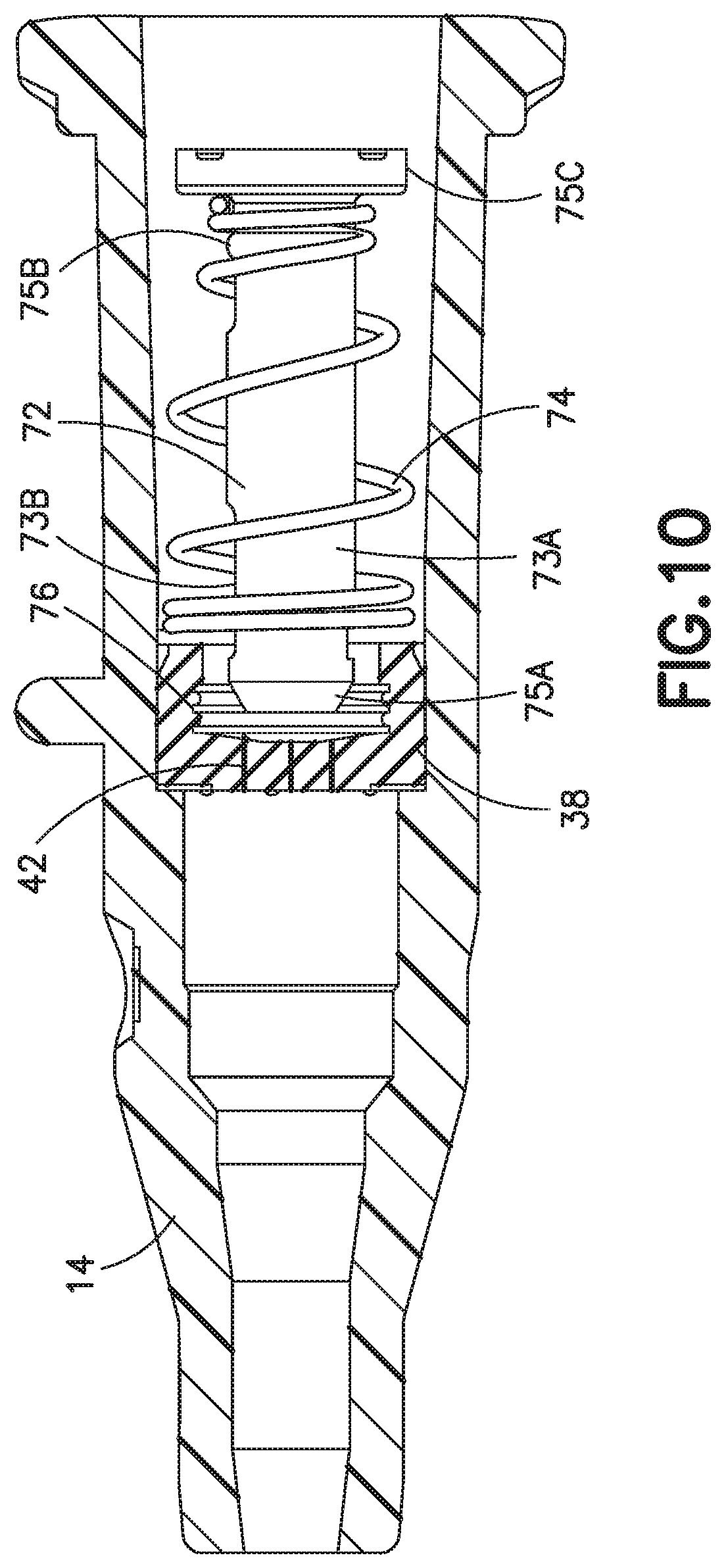
D00013
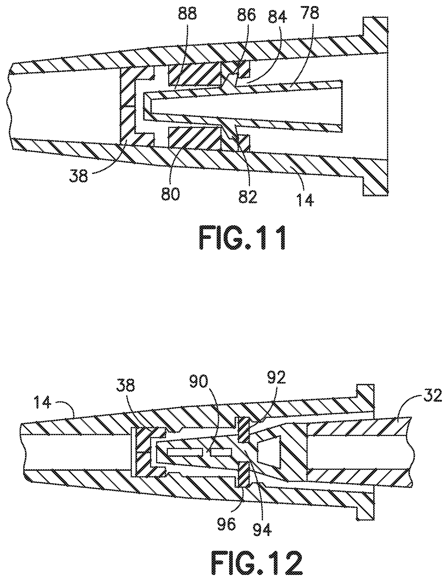
D00014

D00015
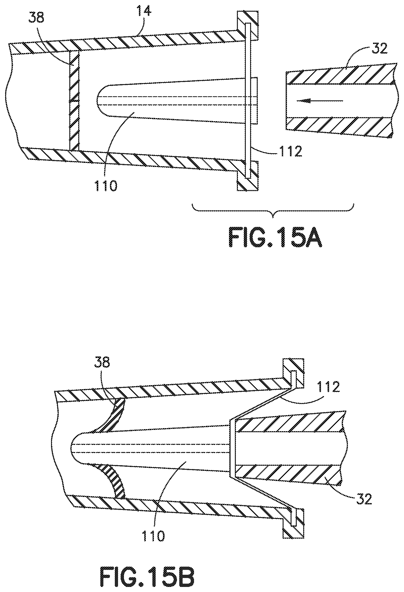
D00016
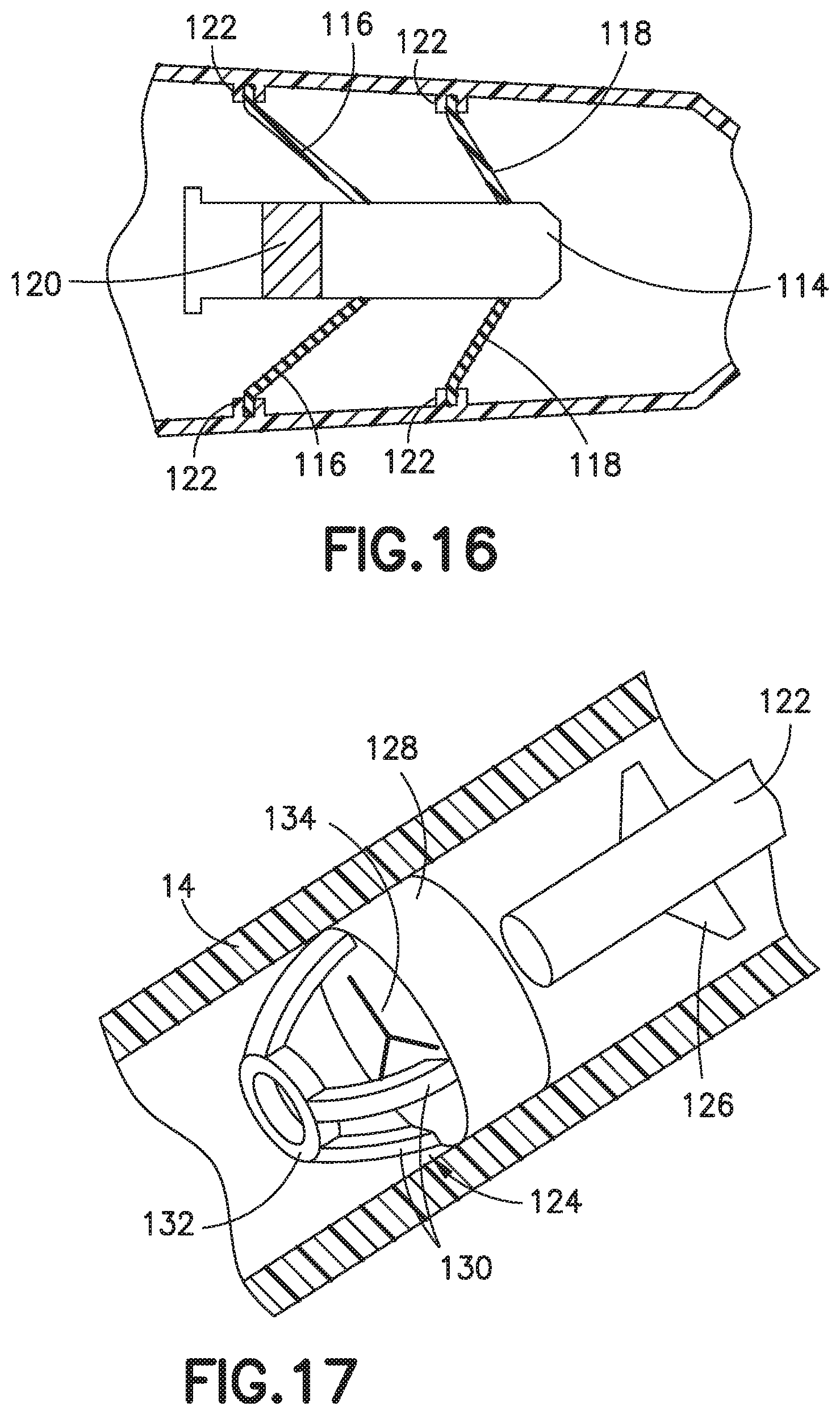
D00017
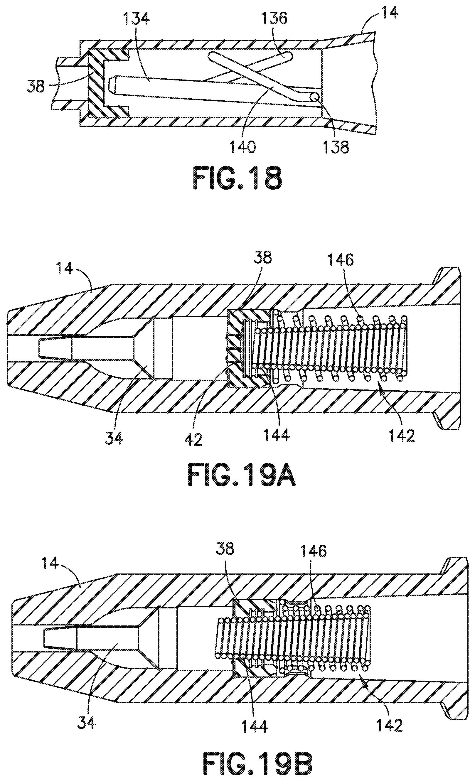
D00018

D00019
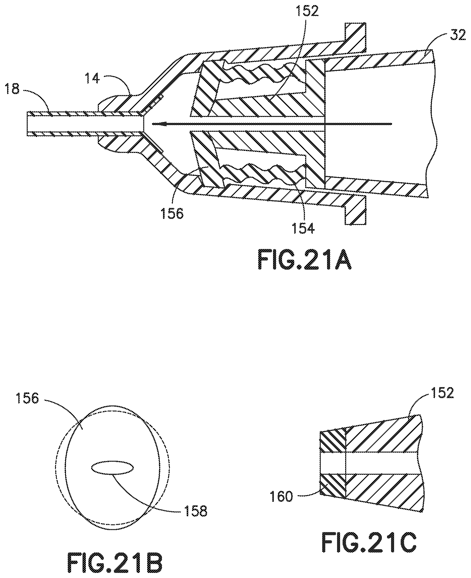
D00020
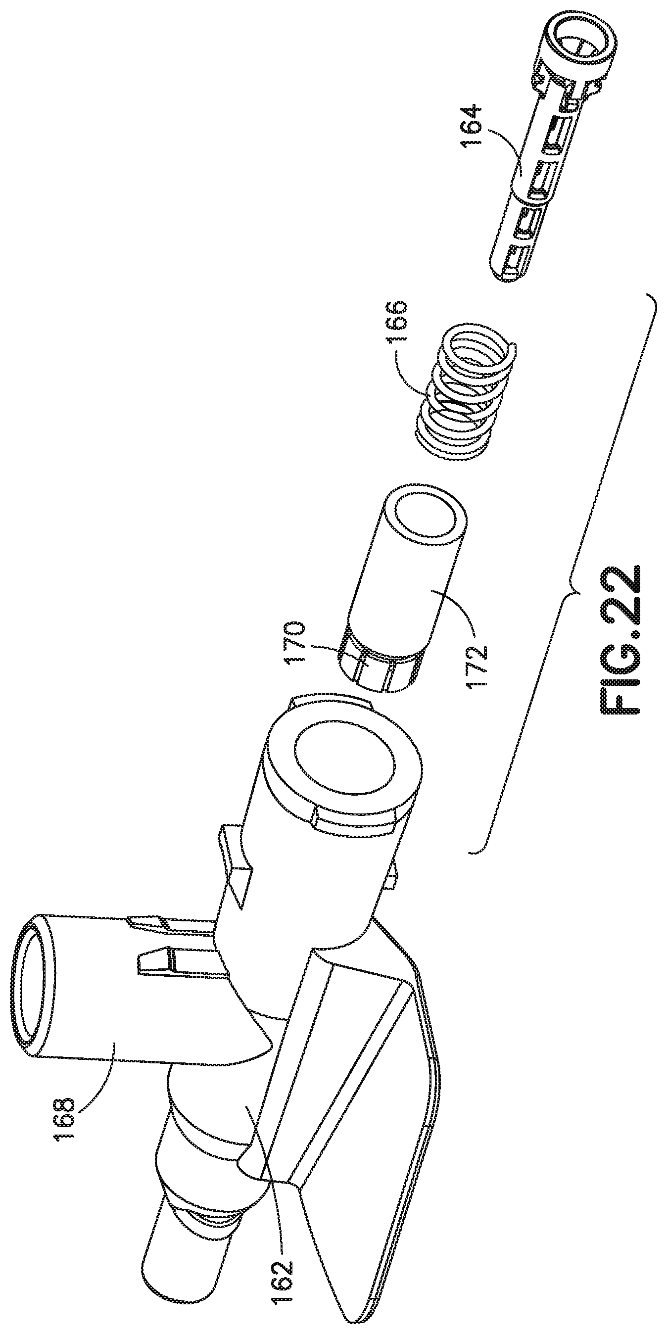
D00021

D00022
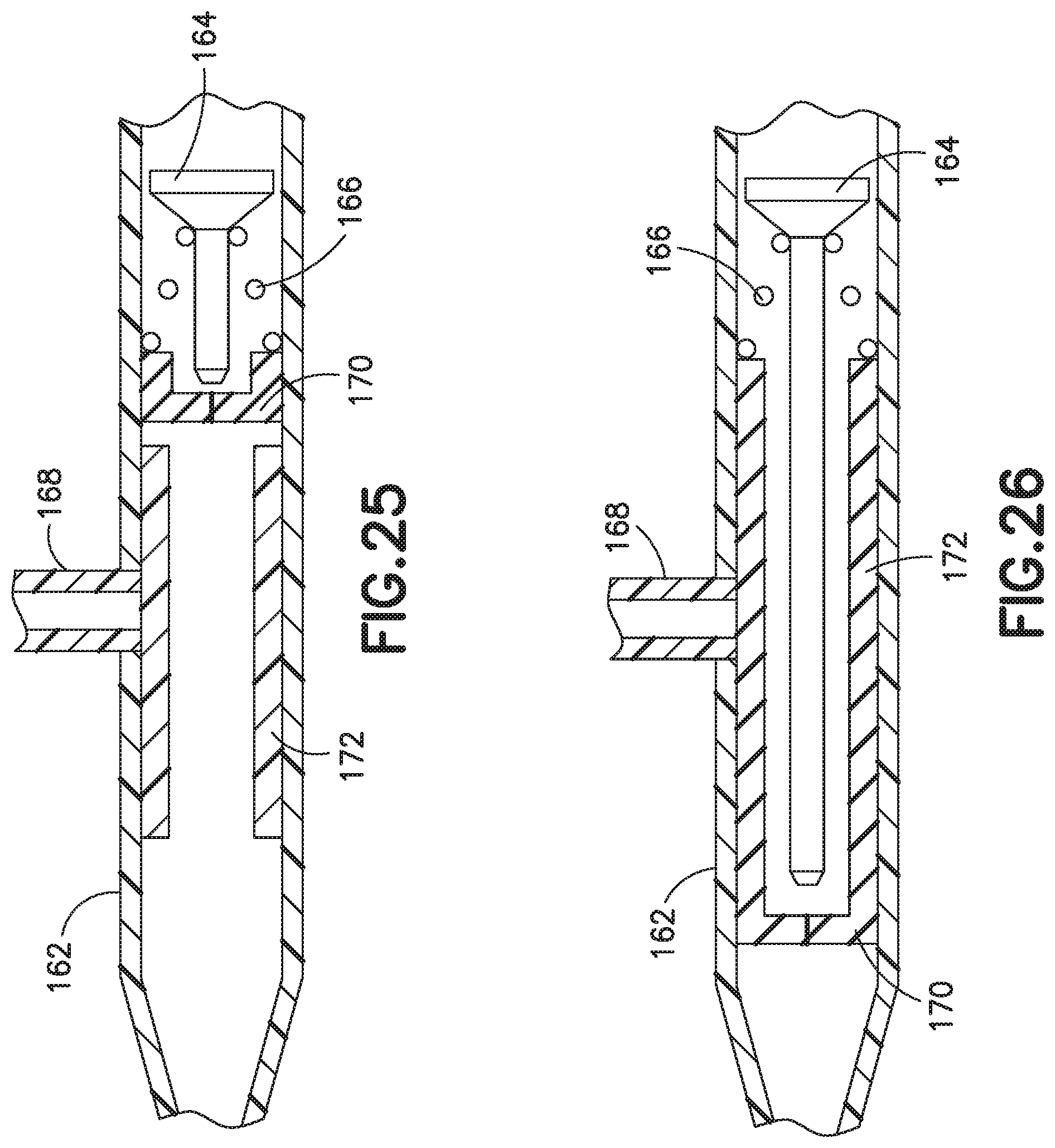
D00023
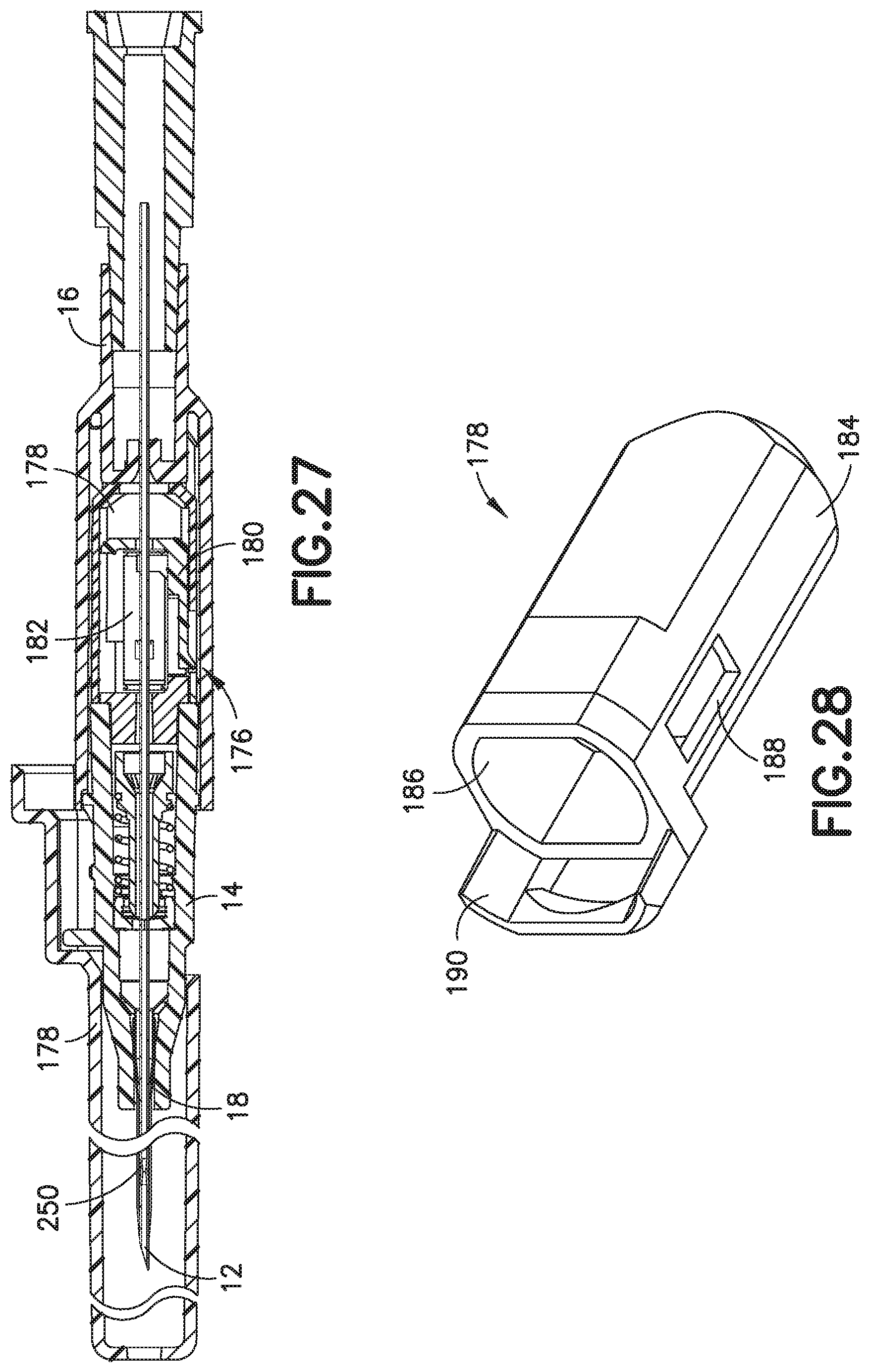
D00024

D00025
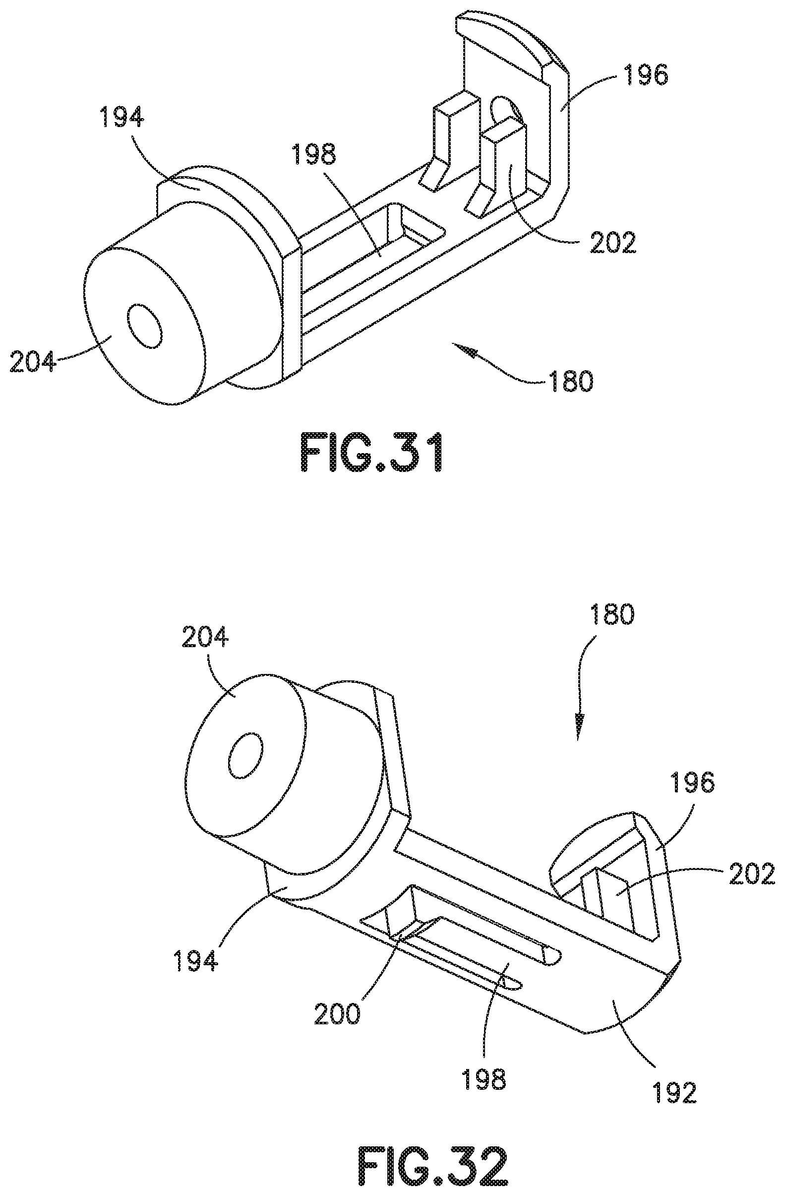
D00026

D00027

D00028

D00029

D00030

D00031
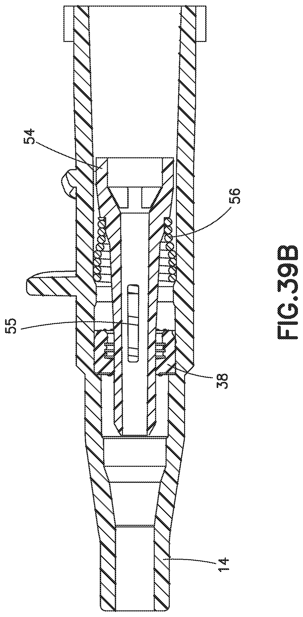
D00032

D00033
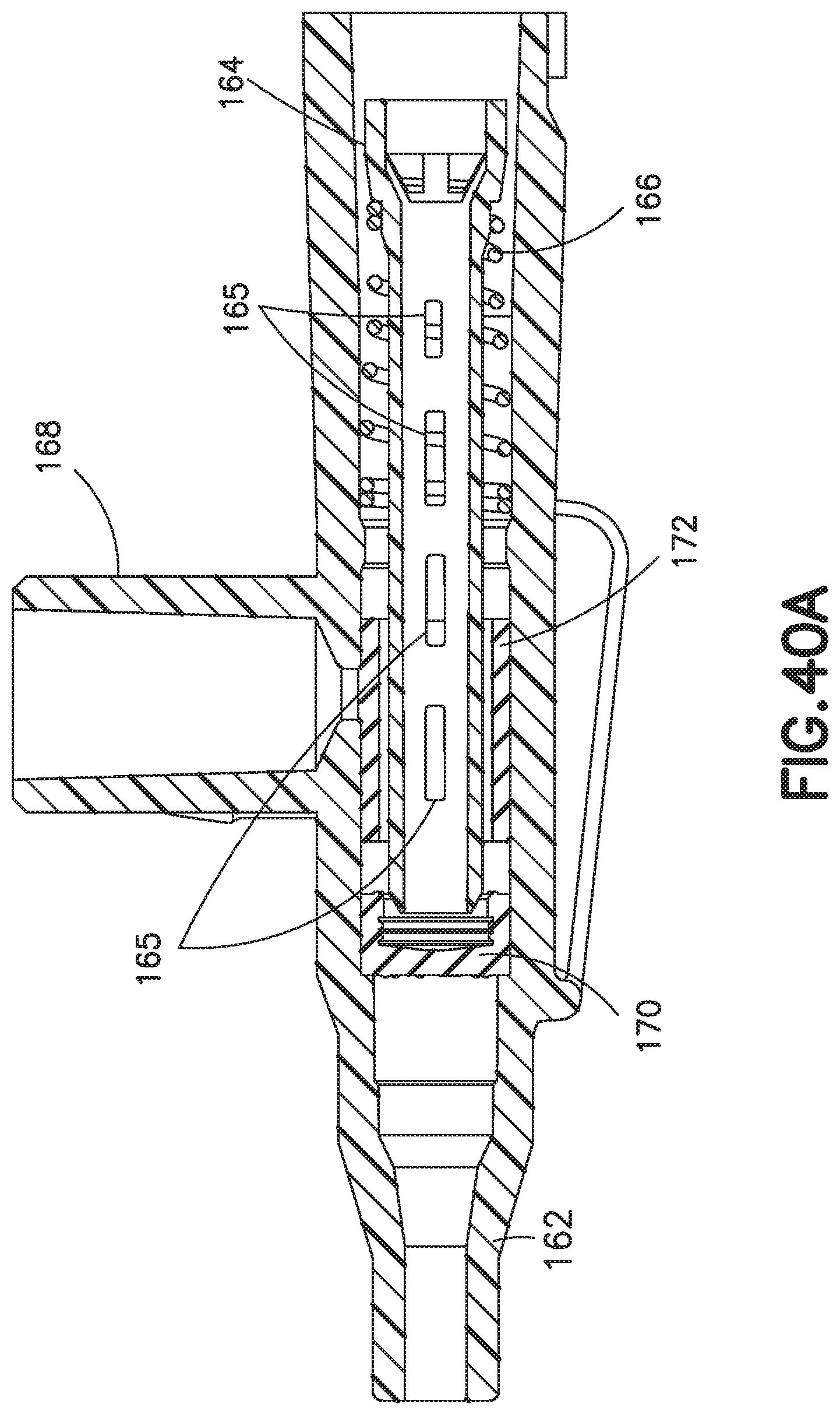
D00034

D00035
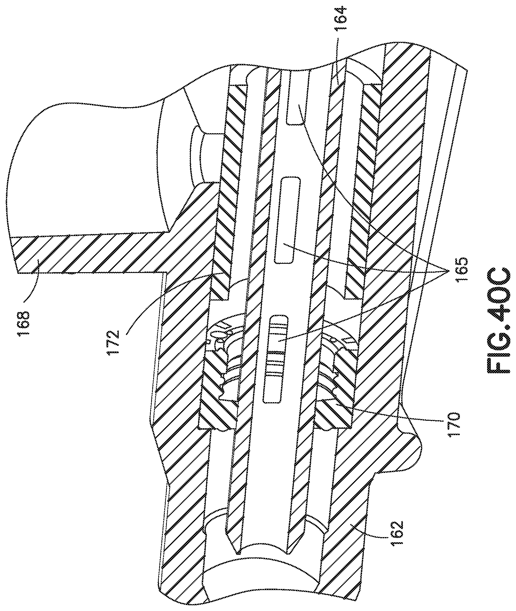
D00036

D00037

D00038

D00039

D00040
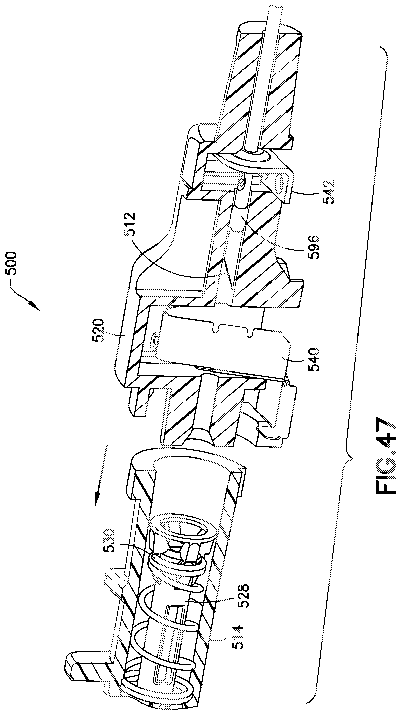
D00041

D00042
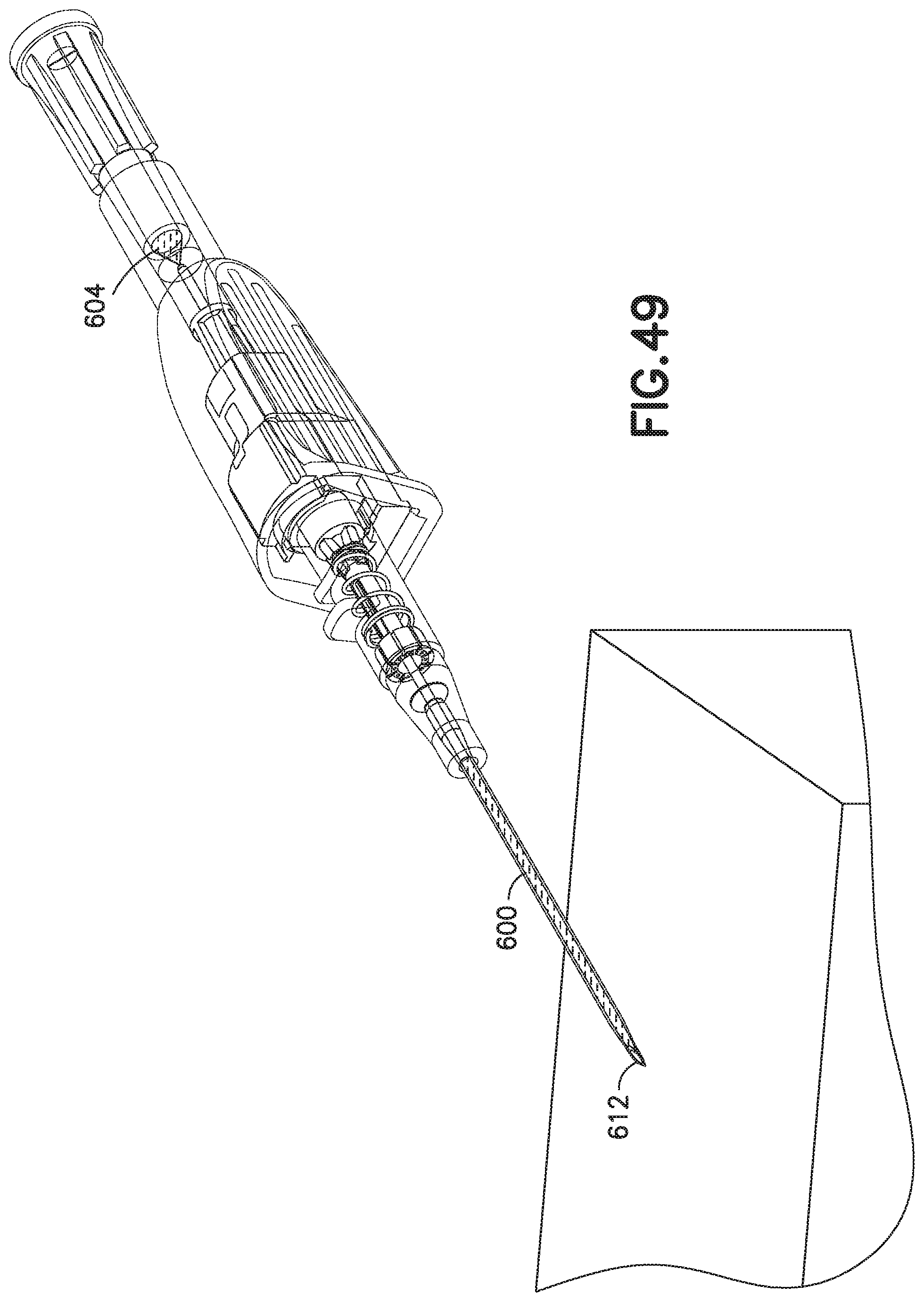
D00043
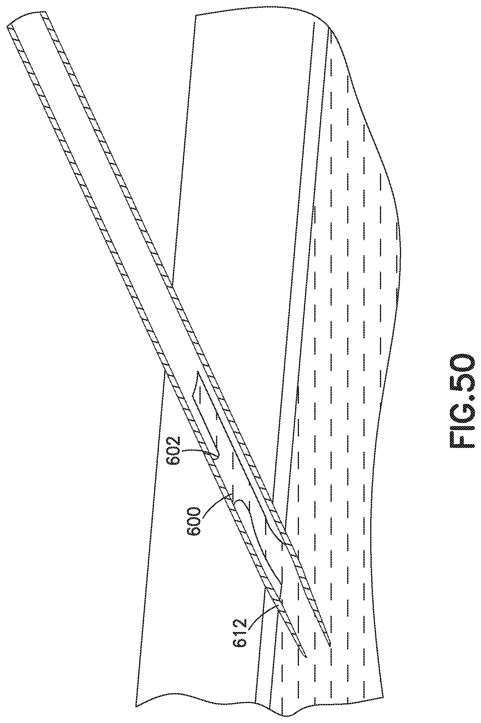
D00044

XML
uspto.report is an independent third-party trademark research tool that is not affiliated, endorsed, or sponsored by the United States Patent and Trademark Office (USPTO) or any other governmental organization. The information provided by uspto.report is based on publicly available data at the time of writing and is intended for informational purposes only.
While we strive to provide accurate and up-to-date information, we do not guarantee the accuracy, completeness, reliability, or suitability of the information displayed on this site. The use of this site is at your own risk. Any reliance you place on such information is therefore strictly at your own risk.
All official trademark data, including owner information, should be verified by visiting the official USPTO website at www.uspto.gov. This site is not intended to replace professional legal advice and should not be used as a substitute for consulting with a legal professional who is knowledgeable about trademark law.