Orthopaedic knee prosthesis having controlled condylar curvature
Heldreth , et al.
U.S. patent number 10,729,551 [Application Number 16/241,386] was granted by the patent office on 2020-08-04 for orthopaedic knee prosthesis having controlled condylar curvature. This patent grant is currently assigned to DePuy Ireland Unlimited Company. The grantee listed for this patent is DEPUY IRELAND UNLIMITED COMPANY. Invention is credited to John M. Armacost, Daniel D. Auger, Said T. Gomaa, Mark A. Heldreth, Jordan S. Lee, Danny W. Rumple, Jr., Dimitri Sokolov, Christel M. Wagner, John L. Williams, Joseph G. Wyss.


View All Diagrams
| United States Patent | 10,729,551 |
| Heldreth , et al. | August 4, 2020 |
Orthopaedic knee prosthesis having controlled condylar curvature
Abstract
An orthopaedic knee prosthesis includes a femoral component having a condyle surface. The condyle surface is defined by one or more radii of curvatures, which are controlled to reduce or delay the onset of anterior translation of the femoral component relative to a tibial bearing.
| Inventors: | Heldreth; Mark A. (Mentone, IN), Auger; Daniel D. (Fort Wayne, IN), Wyss; Joseph G. (Fort Wayne, IN), Rumple, Jr.; Danny W. (Warsaw, IN), Wagner; Christel M. (Plymouth, IN), Sokolov; Dimitri (Campbell, CA), Lee; Jordan S. (Warsaw, IN), Williams; John L. (Fort Wayne, IN), Gomaa; Said T. (Fort Wayne, IN), Armacost; John M. (Warsaw, IN) | ||||||||||
|---|---|---|---|---|---|---|---|---|---|---|---|
| Applicant: |
|
||||||||||
| Assignee: | DePuy Ireland Unlimited Company
(Ringaskiddy, County Cork, IE) |
||||||||||
| Family ID: | 1000004961958 | ||||||||||
| Appl. No.: | 16/241,386 | ||||||||||
| Filed: | January 7, 2019 |
Prior Publication Data
| Document Identifier | Publication Date | |
|---|---|---|
| US 20190133772 A1 | May 9, 2019 | |
Related U.S. Patent Documents
| Application Number | Filing Date | Patent Number | Issue Date | ||
|---|---|---|---|---|---|
| 15402513 | Jan 10, 2017 | 10179051 | |||
| 14309466 | Jan 10, 2017 | 9539099 | |||
| 13540177 | Aug 5, 2014 | 8795380 | |||
| 12488107 | Aug 7, 2012 | 8236061 | |||
| 61077124 | Jun 30, 2008 | ||||
| Current U.S. Class: | 1/1 |
| Current CPC Class: | A61F 2/38 (20130101); A61F 2/3859 (20130101); A61F 2/3868 (20130101); A61F 2/3836 (20130101); A61F 2002/30245 (20130101) |
| Current International Class: | A61F 2/38 (20060101); A61F 2/30 (20060101) |
References Cited [Referenced By]
U.S. Patent Documents
| 3765033 | October 1973 | Goldberg et al. |
| 3840905 | October 1974 | Deane |
| 3852045 | December 1974 | Wheeler et al. |
| 3855638 | December 1974 | Pilliar |
| 3869731 | March 1975 | Waugh et al. |
| 4081866 | April 1978 | Upshaw et al. |
| 4156943 | June 1979 | Collier |
| 4206516 | June 1980 | Pilliar |
| 4209861 | July 1980 | Walker et al. |
| 4215439 | August 1980 | Gold et al. |
| 4249270 | February 1981 | Bahler et al. |
| 4257129 | March 1981 | Volz |
| 4262368 | April 1981 | Lacey |
| 4340978 | July 1982 | Buechel et al. |
| 4470158 | September 1984 | Pappas et al. |
| 4612160 | September 1986 | Donlevy et al. |
| 4673407 | June 1987 | Martin |
| 4714474 | December 1987 | Brooks et al. |
| 4795468 | January 1989 | Hodorek et al. |
| 4808185 | February 1989 | Penenberg et al. |
| 4822362 | April 1989 | Walker et al. |
| 4838891 | June 1989 | Branemark et al. |
| 4888021 | December 1989 | Forte et al. |
| 4938769 | July 1990 | Shaw |
| 4944757 | July 1990 | Martinez et al. |
| 4944760 | July 1990 | Kenna |
| 4950298 | August 1990 | Gustilo et al. |
| 4963152 | October 1990 | Hofmann et al. |
| 4990163 | February 1991 | Ducheyne et al. |
| 5007933 | April 1991 | Sidebotham et al. |
| 5011496 | April 1991 | Forte et al. |
| 5019103 | May 1991 | Van Zile et al. |
| 5037423 | August 1991 | Kenna |
| 5071438 | December 1991 | Jones et al. |
| 5080675 | January 1992 | Ashby et al. |
| 5104410 | April 1992 | Chowdhary |
| 5108442 | April 1992 | Smith |
| 5116375 | May 1992 | Hofmann |
| 5133758 | July 1992 | Hollister |
| 5147405 | September 1992 | Van Zile et al. |
| 5171283 | December 1992 | Pappas et al. |
| 5201766 | April 1993 | Georgette |
| 5219362 | June 1993 | Tuke et al. |
| 5236461 | August 1993 | Forte |
| 5251468 | October 1993 | Lin et al. |
| 5258044 | November 1993 | Lee |
| 5271737 | December 1993 | Baldwin et al. |
| 5282861 | February 1994 | Kaplan |
| 5308556 | May 1994 | Bagley |
| 5309639 | May 1994 | Lee |
| 5326361 | July 1994 | Hollister |
| 5330533 | July 1994 | Walker |
| 5330534 | July 1994 | Herrington et al. |
| 5344460 | September 1994 | Turanyi et al. |
| 5344461 | September 1994 | Phlipot |
| 5344494 | September 1994 | Davidson et al. |
| 5358527 | October 1994 | Forte |
| 5368881 | November 1994 | Kelman et al. |
| 5370699 | December 1994 | Hood et al. |
| 5387240 | February 1995 | Pottenger et al. |
| 5395401 | March 1995 | Bahler |
| 5405396 | April 1995 | Heldreth et al. |
| 5413604 | May 1995 | Hodge |
| 5414049 | May 1995 | Sun et al. |
| 5449745 | September 1995 | Sun et al. |
| 5458637 | October 1995 | Hayes |
| 5480446 | January 1996 | Goodfellow et al. |
| 5543471 | August 1996 | Sun et al. |
| 5549686 | August 1996 | Johnson et al. |
| 5571187 | November 1996 | Devanathan |
| 5571194 | November 1996 | Gabriel |
| 5609639 | March 1997 | Walker |
| 5609643 | March 1997 | Colleran et al. |
| 5639279 | June 1997 | Burkinshaw et al. |
| 5650485 | July 1997 | Sun et al. |
| 5658333 | August 1997 | Kelman et al. |
| 5658342 | August 1997 | Draganich et al. |
| 5658344 | August 1997 | Hurlburt |
| 5681354 | October 1997 | Eckhoff |
| 5683468 | November 1997 | Pappas |
| 5702458 | December 1997 | Burstein et al. |
| 5702463 | December 1997 | Pothier et al. |
| 5702464 | December 1997 | Lackey et al. |
| 5702466 | December 1997 | Pappas et al. |
| 5728748 | March 1998 | Sun et al. |
| 5732469 | March 1998 | Hamamoto et al. |
| 5755800 | May 1998 | O'Neil et al. |
| 5755801 | May 1998 | Walker et al. |
| 5755803 | May 1998 | Haines et al. |
| 5765095 | June 1998 | Flak et al. |
| 5766257 | June 1998 | Goodman et al. |
| 5776201 | July 1998 | Colleran et al. |
| 5800552 | September 1998 | Forte |
| 5811543 | September 1998 | Hao et al. |
| 5824096 | October 1998 | Pappas et al. |
| 5824100 | October 1998 | Kester et al. |
| 5824102 | October 1998 | Buscayret |
| 5824103 | October 1998 | Williams |
| 5871543 | February 1999 | Hofmann |
| 5871545 | February 1999 | Goodfellow et al. |
| 5871546 | February 1999 | Colleran et al. |
| 5879394 | March 1999 | Ashby et al. |
| 5879400 | March 1999 | Merrill et al. |
| 5906644 | May 1999 | Powell |
| 5935173 | August 1999 | Roger et al. |
| 5951603 | September 1999 | O'Neil et al. |
| 5957979 | September 1999 | Beckman et al. |
| 5964808 | October 1999 | Blaha et al. |
| 5976147 | November 1999 | Lasalle et al. |
| 5984969 | November 1999 | Matthews et al. |
| 5989027 | November 1999 | Wagner et al. |
| 5997577 | December 1999 | Herrington et al. |
| 6004351 | December 1999 | Tomita et al. |
| 6005018 | December 1999 | Cicierega et al. |
| 6010534 | January 2000 | O'Neil et al. |
| 6013103 | January 2000 | Kaufman et al. |
| 6017975 | January 2000 | Saum et al. |
| 6039764 | March 2000 | Pottenger et al. |
| 6042780 | March 2000 | Huang |
| 6053945 | April 2000 | O'Neil et al. |
| 6059949 | May 2000 | Gal-Or et al. |
| 6068658 | May 2000 | Insall et al. |
| 6080195 | June 2000 | Colleran et al. |
| 6090144 | July 2000 | Letot et al. |
| 6123728 | September 2000 | Brosnahan et al. |
| 6123729 | September 2000 | Insall et al. |
| 6123896 | September 2000 | Meeks et al. |
| 6126692 | October 2000 | Robie et al. |
| 6135857 | October 2000 | Shaw et al. |
| 6139581 | October 2000 | Engh et al. |
| 6152960 | November 2000 | Pappas |
| 6162254 | December 2000 | Timoteo |
| 6174934 | January 2001 | Sun et al. |
| 6206926 | March 2001 | Pappas |
| 6210444 | April 2001 | Webster et al. |
| 6210445 | April 2001 | Zawadzki |
| 6217618 | April 2001 | Hileman |
| 6228900 | May 2001 | Shen et al. |
| 6238434 | May 2001 | Pappas |
| 6242507 | June 2001 | Saum et al. |
| 6245276 | June 2001 | McNulty et al. |
| 6258127 | July 2001 | Schmotzer |
| 6264697 | July 2001 | Walker |
| 6280476 | August 2001 | Metzger et al. |
| 6281264 | August 2001 | Salovey et al. |
| 6299646 | October 2001 | Chambat et al. |
| 6316158 | November 2001 | Saum et al. |
| 6319283 | November 2001 | Insall et al. |
| 6325828 | December 2001 | Dennis et al. |
| 6344059 | February 2002 | Krakovits et al. |
| 6361564 | March 2002 | Marceaux et al. |
| 6372814 | April 2002 | Sun et al. |
| 6379388 | April 2002 | Ensign et al. |
| 6428577 | August 2002 | Evans et al. |
| 6443991 | September 2002 | Running |
| 6475241 | November 2002 | Pappas |
| 6485519 | November 2002 | Meyers et al. |
| 6491726 | December 2002 | Pappas |
| 6494914 | December 2002 | Brown et al. |
| 6503280 | January 2003 | Repicci |
| 6506215 | January 2003 | Letot et al. |
| 6506216 | January 2003 | McCue et al. |
| 6524522 | February 2003 | Vaidyanathan et al. |
| 6540787 | April 2003 | Biegun et al. |
| 6558426 | May 2003 | Masini |
| 6569202 | May 2003 | Whiteside |
| 6582469 | June 2003 | Tornier |
| 6582470 | June 2003 | Lee et al. |
| 6589283 | July 2003 | Metzger et al. |
| 6592787 | July 2003 | Pickrell et al. |
| 6620198 | September 2003 | Burstein et al. |
| 6623526 | September 2003 | Lloyd |
| 6645251 | November 2003 | Salehi et al. |
| 6660039 | December 2003 | Evans et al. |
| 6660224 | December 2003 | Lefebvre et al. |
| 6664308 | December 2003 | Sun et al. |
| 6702821 | March 2004 | Bonutti |
| 6719800 | April 2004 | Meyers et al. |
| 6726724 | April 2004 | Repicci |
| 6730128 | May 2004 | Burstein |
| 6764516 | July 2004 | Pappas |
| 6770078 | August 2004 | Bonutti |
| 6770099 | August 2004 | Andriacchi et al. |
| 6773461 | August 2004 | Meyers et al. |
| 6797005 | September 2004 | Pappas |
| 6818020 | November 2004 | Sun et al. |
| 6846327 | January 2005 | Khandkar et al. |
| 6846329 | January 2005 | McMinn |
| 6849230 | February 2005 | Feichtinger |
| 6852272 | February 2005 | Artz et al. |
| 6869448 | March 2005 | Tuke et al. |
| 6893388 | May 2005 | Reising et al. |
| 6893467 | May 2005 | Bercovy |
| 6916340 | July 2005 | Metzger et al. |
| 6923832 | August 2005 | Sharkey et al. |
| 6926738 | August 2005 | Wyss |
| 6942670 | September 2005 | Heldreth et al. |
| 6972039 | December 2005 | Metzger et al. |
| 6986791 | January 2006 | Metzger |
| 7025788 | April 2006 | Metzger et al. |
| 7048741 | May 2006 | Swanson |
| 7066963 | June 2006 | Naegerl |
| 7070622 | July 2006 | Brown et al. |
| 7081137 | July 2006 | Servidio |
| 7094259 | August 2006 | Tarabichi |
| 7101401 | September 2006 | Brack |
| 7104996 | September 2006 | Bonutti |
| 7105027 | September 2006 | Lipman et al. |
| 7147819 | December 2006 | Bram et al. |
| 7160330 | January 2007 | Axelson, Jr. et al. |
| 7175665 | February 2007 | German et al. |
| 7255715 | August 2007 | Metzger |
| 7261740 | August 2007 | Tuttle et al. |
| 7297164 | November 2007 | Johnson et al. |
| 7326252 | February 2008 | Otto et al. |
| 7341602 | March 2008 | Fell et al. |
| 7344460 | March 2008 | Gait |
| 7357817 | April 2008 | D'Alessio, II |
| 7422605 | September 2008 | Burstein et al. |
| 7510557 | March 2009 | Bonutti |
| 7527650 | May 2009 | Johnson et al. |
| 7572292 | August 2009 | Crabtree et al. |
| 7578850 | August 2009 | Kuczynski et al. |
| 7608079 | October 2009 | Blackwell et al. |
| 7611519 | November 2009 | Lefevre et al. |
| 7615054 | November 2009 | Bonutti |
| 7618462 | November 2009 | Ek |
| 7628818 | December 2009 | Hazebrouck et al. |
| 7635390 | December 2009 | Bonutti |
| 7658767 | February 2010 | Wyss |
| 7678151 | March 2010 | Ek |
| 7678152 | March 2010 | Suguro et al. |
| 7708740 | May 2010 | Bonutti |
| 7708741 | May 2010 | Bonutti |
| 7740662 | June 2010 | Barnett et al. |
| 7749229 | July 2010 | Bonutti |
| 7753960 | July 2010 | Cipolletti et al. |
| 7771484 | August 2010 | Campbell |
| 7776044 | August 2010 | Pendleton et al. |
| 7806896 | October 2010 | Bonutti |
| 7806897 | October 2010 | Bonutti |
| 7837736 | November 2010 | Bonutti |
| 7842093 | November 2010 | Peters et al. |
| 7875081 | January 2011 | Lipman et al. |
| 7922771 | April 2011 | Otto et al. |
| 8187335 | May 2012 | Wyss et al. |
| 8192498 | June 2012 | Wagner et al. |
| 8206451 | June 2012 | Wyss et al. |
| 8236061 | August 2012 | Heldreth et al. |
| 8795380 | August 2014 | Heldreth et al. |
| 9539099 | January 2017 | Heldreth et al. |
| 2002/0138150 | September 2002 | Leclercq |
| 2003/0009232 | January 2003 | Metzger et al. |
| 2003/0035747 | February 2003 | Anderson et al. |
| 2003/0044301 | March 2003 | Lefebvre et al. |
| 2003/0075013 | April 2003 | Grohowski |
| 2003/0139817 | July 2003 | Tuke et al. |
| 2003/0153981 | August 2003 | Wang et al. |
| 2003/0171820 | September 2003 | Wilshaw et al. |
| 2003/0199985 | October 2003 | Masini |
| 2003/0212161 | November 2003 | McKellop et al. |
| 2003/0225456 | December 2003 | Ek |
| 2004/0015770 | January 2004 | Kimoto |
| 2004/0039450 | February 2004 | Griner et al. |
| 2004/0167633 | August 2004 | Wen et al. |
| 2004/0186583 | September 2004 | Keller |
| 2004/0215345 | October 2004 | Perrone, Jr. et al. |
| 2004/0243244 | December 2004 | Otto et al. |
| 2004/0243245 | December 2004 | Plumet et al. |
| 2005/0021147 | January 2005 | Tarabichi |
| 2005/0055102 | March 2005 | Tornier et al. |
| 2005/0059750 | March 2005 | Sun et al. |
| 2005/0069629 | March 2005 | Becker et al. |
| 2005/0096747 | May 2005 | Tuttle et al. |
| 2005/0100578 | May 2005 | Schmid et al. |
| 2005/0123672 | June 2005 | Justin et al. |
| 2005/0143832 | June 2005 | Carson |
| 2005/0154472 | July 2005 | Afriat |
| 2005/0203631 | September 2005 | Daniels et al. |
| 2005/0209701 | September 2005 | Suguro et al. |
| 2005/0209702 | September 2005 | Todd et al. |
| 2005/0249625 | November 2005 | Brain et al. |
| 2005/0278035 | December 2005 | Wyss et al. |
| 2006/0002810 | January 2006 | Grohowski |
| 2006/0015185 | January 2006 | Chambat et al. |
| 2006/0036329 | February 2006 | Webster et al. |
| 2006/0052875 | March 2006 | Bernero et al. |
| 2006/0100714 | May 2006 | Ensign |
| 2006/0178749 | August 2006 | Pendleton et al. |
| 2006/0195195 | August 2006 | Burstein et al. |
| 2006/0228247 | October 2006 | Grohowski |
| 2006/0231402 | October 2006 | Clasen et al. |
| 2006/0241781 | October 2006 | Brown et al. |
| 2006/0257358 | November 2006 | Wen et al. |
| 2006/0271191 | November 2006 | Hermansson |
| 2006/0289388 | December 2006 | Yang et al. |
| 2007/0061014 | March 2007 | Naegerl |
| 2007/0073409 | March 2007 | Cooney et al. |
| 2007/0078521 | April 2007 | Overholser et al. |
| 2007/0100463 | May 2007 | Aram et al. |
| 2007/0129809 | June 2007 | Meridew et al. |
| 2007/0135926 | June 2007 | Walker |
| 2007/0173948 | July 2007 | Meridew et al. |
| 2007/0196230 | August 2007 | Hamman et al. |
| 2007/0203582 | August 2007 | Campbell |
| 2007/0219639 | September 2007 | Otto et al. |
| 2007/0293647 | December 2007 | McKellop et al. |
| 2008/0004708 | January 2008 | Wyss |
| 2008/0021566 | January 2008 | Peters et al. |
| 2008/0091272 | April 2008 | Aram et al. |
| 2008/0097616 | April 2008 | Meyers et al. |
| 2008/0114462 | May 2008 | Guidera et al. |
| 2008/0114464 | May 2008 | Barnett et al. |
| 2008/0119940 | May 2008 | Otto et al. |
| 2008/0161927 | July 2008 | Savage et al. |
| 2008/0195108 | August 2008 | Bhatnagar et al. |
| 2008/0199720 | August 2008 | Liu |
| 2008/0206297 | August 2008 | Roeder et al. |
| 2008/0269596 | October 2008 | Revie et al. |
| 2009/0043396 | February 2009 | Komistek |
| 2009/0048680 | February 2009 | Naegerl |
| 2009/0082873 | March 2009 | Hazebrouck et al. |
| 2009/0084491 | April 2009 | Uthgenannt et al. |
| 2009/0088859 | April 2009 | Hazebrouck et al. |
| 2009/0125114 | May 2009 | May et al. |
| 2009/0192610 | July 2009 | Case et al. |
| 2009/0265012 | October 2009 | Engh et al. |
| 2009/0265013 | October 2009 | Mandell |
| 2009/0292365 | November 2009 | Smith et al. |
| 2009/0295035 | December 2009 | Evans |
| 2009/0306785 | December 2009 | Farrar et al. |
| 2009/0319047 | December 2009 | Walker |
| 2009/0326663 | December 2009 | Dun |
| 2009/0326664 | December 2009 | Wagner et al. |
| 2009/0326665 | December 2009 | Wyss et al. |
| 2009/0326666 | December 2009 | Wyss et al. |
| 2009/0326667 | December 2009 | Williams et al. |
| 2009/0326674 | December 2009 | Liu et al. |
| 2010/0016979 | January 2010 | Wyss et al. |
| 2010/0036499 | February 2010 | Pinskerova |
| 2010/0036500 | February 2010 | Heldreth et al. |
| 2010/0042224 | February 2010 | Otto et al. |
| 2010/0042225 | February 2010 | Shur |
| 2010/0063594 | March 2010 | Hazebrouck et al. |
| 2010/0070045 | March 2010 | Ek |
| 2010/0076563 | March 2010 | Otto et al. |
| 2010/0076564 | March 2010 | Schilling et al. |
| 2010/0094429 | April 2010 | Otto |
| 2010/0098574 | April 2010 | Liu et al. |
| 2010/0100189 | April 2010 | Metzger |
| 2010/0100190 | April 2010 | May et al. |
| 2010/0100191 | April 2010 | May et al. |
| 2010/0125337 | May 2010 | Grecco et al. |
| 2010/0161067 | June 2010 | Saleh et al. |
| 2010/0191341 | July 2010 | Byrd |
| 2010/0222890 | September 2010 | Barnett et al. |
| 2010/0286788 | November 2010 | Komistek |
| 2010/0292804 | November 2010 | Samuelson |
| 2010/0305710 | December 2010 | Metzger et al. |
| 2010/0312350 | December 2010 | Bonutti |
| 2011/0029090 | February 2011 | Zannis et al. |
| 2011/0029092 | February 2011 | Deruntz et al. |
| 2011/0035017 | February 2011 | Deffenbaugh et al. |
| 2011/0035018 | February 2011 | Deffenbaugh et al. |
| 2011/0106268 | May 2011 | Deffenbaugh et al. |
| 2011/0118847 | May 2011 | Lipman et al. |
| 2011/0125280 | May 2011 | Otto et al. |
| 2011/0153026 | June 2011 | Heggendorn et al. |
| 2012/0239158 | September 2012 | Wagner et al. |
| 2012/0259417 | October 2012 | Wyss et al. |
| 2012/0296437 | November 2012 | Wyss et al. |
| 2013/0006372 | January 2013 | Wyss et al. |
| 2013/0006373 | January 2013 | Wyss et al. |
| 1803106 | Jul 2006 | CN | |||
| 1872009 | Dec 2006 | CN | |||
| 4308563 | Sep 1994 | DE | |||
| 19529824 | Feb 1997 | DE | |||
| 495340 | Jul 1992 | EP | |||
| 510178 | Oct 1992 | EP | |||
| 634155 | Jan 1995 | EP | |||
| 634156 | Jan 1995 | EP | |||
| 636352 | Feb 1995 | EP | |||
| 0636352 | Feb 1995 | EP | |||
| 732091 | Sep 1996 | EP | |||
| 732092 | Sep 1996 | EP | |||
| 765645 | Apr 1997 | EP | |||
| 883388 | Dec 1998 | EP | |||
| 1129676 | Sep 2001 | EP | |||
| 1196118 | Apr 2002 | EP | |||
| 1226799 | Jul 2002 | EP | |||
| 1374805 | Jan 2004 | EP | |||
| 1421918 | May 2004 | EP | |||
| 1440675 | Jul 2004 | EP | |||
| 1470801 | Oct 2004 | EP | |||
| 1518521 | Mar 2005 | EP | |||
| 1591082 | Nov 2005 | EP | |||
| 1779812 | May 2007 | EP | |||
| 1923079 | May 2008 | EP | |||
| 2417971 | Sep 1979 | FR | |||
| 2621243 | Apr 1989 | FR | |||
| 2653992 | May 1991 | FR | |||
| 2780636 | Jan 2000 | FR | |||
| 2787012 | Jun 2000 | FR | |||
| 2809302 | Nov 2001 | FR | |||
| 2835178 | Aug 2003 | FR | |||
| 1065354 | Apr 1967 | GB | |||
| 2293109 | Mar 1996 | GB | |||
| 2335145 | Sep 1999 | GB | |||
| 62205201 | Sep 1987 | JP | |||
| H08500992 | Feb 1996 | JP | |||
| H08224263 | Sep 1996 | JP | |||
| 2002291779 | Oct 2002 | JP | |||
| 2004167255 | Jun 2004 | JP | |||
| 2006015133 | Jan 2006 | JP | |||
| 2009501393 | Jan 2009 | JP | |||
| 7900739 | Oct 1979 | WO | |||
| 8100784 | Mar 1981 | WO | |||
| 8906947 | Aug 1989 | WO | |||
| 9014806 | Dec 1990 | WO | |||
| 9601725 | Jan 1996 | WO | |||
| 9623458 | Aug 1996 | WO | |||
| 9624311 | Aug 1996 | WO | |||
| 9624312 | Aug 1996 | WO | |||
| 9846171 | Oct 1998 | WO | |||
| 9927872 | Jun 1999 | WO | |||
| 0209624 | Dec 1999 | WO | |||
| 9966864 | Dec 1999 | WO | |||
| 03039609 | May 2003 | WO | |||
| 03101647 | Dec 2003 | WO | |||
| 2004058108 | Jul 2004 | WO | |||
| 2004069104 | Aug 2004 | WO | |||
| 05009489 | Feb 2005 | WO | |||
| 05009729 | Feb 2005 | WO | |||
| 2005072657 | Aug 2005 | WO | |||
| 2005087125 | Sep 2005 | WO | |||
| 06014294 | Feb 2006 | WO | |||
| 06130350 | Dec 2006 | WO | |||
| 2007106172 | Sep 2007 | WO | |||
| 2007108804 | Sep 2007 | WO | |||
| 2007119173 | Oct 2007 | WO | |||
| 09046212 | Apr 2009 | WO | |||
| 09128943 | Oct 2009 | WO | |||
Other References
|
Ries, "Effect of ACL Sacrifice, Retention, or Substitution on K After TKA," http://www.orthosupersite.com/view.asp?rID=23134, Aug. 2007, 5 pgs. cited by applicant . Zimmer Nexgen Trabecular Metal Tibial Tray, The Best Thing Next to Bone, 97-5954-001-00, 2007, 4 pages. cited by applicant . European Search Report for European Patent Application No. 08253140.1-2310, dated Dec. 23, 2008, 7 pgs. cited by applicant . Koo, et al., "The Knee Joint Center of Rotation Is Predominantly on the Lateral Side During Normal Walking", Journal of Biomechanics, vol. 41 (2008): 1269-1273, 5 Pages. cited by applicant . "NexGen Complete Knee Solution Cruciate Retaining Knee (CR)," Zimmer, available at: http://zimmer.com.au/ctl?template=PC&op=global&action=&template=PC&id=356- - , downloaded on Feb. 18, 2009, (1 page). cited by applicant . "Vanguard Complete Knee System," Biomet, available at: http://www.biomet.com/patients/vanguard_complete.cfm, downloaded on Feb. 2009, (3 pages). cited by applicant . Biomet, Vanguard Mono-Lock Tibial System, Patented Convertible Tibial Bearing Technology, 2009, 2 Pages. cited by applicant . European Patent Office, Search Report for App. No. 09164479.9-2310, dated Nov. 4, 2009, 6 pages. cited by applicant . European Search Report for European Patent Application No. 08164944.4-2310-2042131, dated Mar. 16, 2009, 12 pgs. cited by applicant . European Search Report for European Patent Application No. 09164235.5-1526, dated Dec. 22, 2009, 6 pgs. cited by applicant . European Search Report for European Patent Application No. 09164245.4-2310, dated Oct. 15, 2009, 5 pgs. cited by applicant . European Search Report by for European Patent Application No. 09164478.1-2310, dated Oct. 20, 2009, 6 Pages. cited by applicant . Japanese Search Report for Japanese Patent Application No. 2009-501393, dated Oct. 26, 2010, 5 Pages. cited by applicant . Karachalios, et al., "A Mid-Term Clinical Outcome Study of the Advance Medial Pivot Knee Arthroplasty", www.sciencedirect.come, The Knee 16 (2009); 484-488, 5 Pages. cited by applicant . Mannan, et al., "The Medical Rotation Total Knee Replacement: A Clinical and Radiological Review at a Mean Follow-Up of Six Years", The Journal of Bone and Joint Surgery, vol. 91-B, No. 6 (Jun. 2009): 750-756, 7 Pages. cited by applicant . Moonot, et al., "Correlation Between the Oxford Knee and American Knee Society Scores at Mid-Term Follow-Up", The Journal of Knee Surgery, vol. 22, No. 3 (Jul. 2009), 226-230, 5 Page. cited by applicant . Omori, et al., "The Effect of Geometry of the Tibial Polyethylene Insert on the Tibiofemoral Contact Kinematics in Advance Medical Pivot Total Knee Arthroplasty", The Journal of Orthopaedics Science (2009), 14:754-760, 7 Pages. cited by applicant . Zimmer, Trabecular Metal Monoblock Tibial Components, An Optimal Combination of Material and Design, www.zimmer.com, 2009, 3 pages. cited by applicant . Barnes, C.L., et al, "Kneeling Is Safe for Patients Implanted With Medical-Pivot Total Knee Arthoplasty Designs, Journal of Arthoplasty", vol. 00, No. 0 2010, 1-6, 6 Pages. cited by applicant . Depuy Orthopaedics, Inc., "Sigma Fixed Bearing Knees--Function with Wear Resistance", 2010, 0612-65-508 (Rev. 1) 20 pages. cited by applicant . European Search Report for European Patent Application No. 06739287.8-2310, dated Mar. 16, 2010, 3 Pages. cited by applicant . European Search Report for European Patent Application No. 09164160.5-1526, dated Jan. 4, 2010, 4 pgs. cited by applicant . European Search Report for European Patent Application No. 09164168.8-1526, dated Jan. 4, 2010, 6 pgs. cited by applicant . European Search Report for European Patent Application No. 09164228.0-1526, dated Feb. 2, 2010, 6 pgs. cited by applicant . European Search Report for European Patent Application No. 09164478.1-2310, dated Apr. 28, 2010, 12 Pages. cited by applicant . European Search Report for European Patent Application No. 10162138.1, dated Aug. 30, 2010, 7 Pages. cited by applicant . European Search Report, European Application No. 10174439.9-1526, dated Dec. 20, 2010, 4 pages. cited by applicant . Fan, Cheng-Yu, et al., "Primitive Results After Medical-Pivot Knee Arthroplasties: A Minimum 5 Year Follow-Up Study", The Journal of Arthroplasty, vol. 25, No. 3 2010, 492-496, 5 Pages. cited by applicant . Depuy Knees International, "Sigma CR Porocoat.RTM.," 1 page, (downloaded May 12, 2011). cited by applicant . European Search Report for European Patent Application No. 11150648.1-2310, dated Apr. 7, 2011, 4 pages. cited by applicant . European Search Report for European Patent Application No. 11150648.1-2310, dated Apr. 7, 2011, 5 Pgs. cited by applicant . State Intellectual Property Office of People's Republic China; Chinese Search Report; Application No. 200910166935.6; dated Mar. 26, 2013; 2 pages. cited by applicant . Dennis et al., Multicenter Determination of In Vivo Kinematics After Total Knee Arthroplasty, "Clin. Orthop. Rel. Res., 416, 37-57, 21 pgs." cited by applicant . PEEK-OPTIMA.RTM., The Polymer for Implants, Technical Information for the Medical Professional ", 7 pages." cited by applicant . Operative Technique, Johnson Elloy Knee System, Chas F. Thackray, Ltd., 1988, 34 pgs. cited by applicant . Effects of Coronal Plane Conformity on Tibial Loading in TKA: A Comparison of AGC Flat Versus Conforming Articulations, Brent, et al, Orthopaedic Surgery, Surgical Technology International, XVIII, 6 pages. cited by applicant . Scorpio Knee TS Single Axis Revision Knee System, Stryker Orthopaedics, http://www.stryker.com/stellent/groups/public/documents/web_prod/023609.p- - df, (6 pages). cited by applicant . Shaw et al., "The Longitudinal Axis of the Knee and the Role of the Cruciate Ligaments in Controlling Transverse Rotation", J.Bone Joint Surg. Am. 1974:56:1603-1609, 8 Pages. cited by applicant . Goodfellow et al., "The Mechanics of the Knee and Prosthesis Design," The Journal of Bone and Joint Surgery, vol. 60-B, No. 3, Aug. 1978, 12 pgs. cited by applicant . Clary et al., "Kinematics of Posterior Stabilized and Cruciate Retaining Knee Implants During an in Vitro Deep Knee Bend," 54th Annual Meeting of the Orthopaedic Research Society, Poster No. 1983, Mar. 2008. cited by applicant . Kurosawa, et al., "Geometry and Motion of the Knee for Implant and Orthotic Design", The Journal of Biomechanics 18 (1985), pp. 487-499, 12 Pages. cited by applicant . 2nd Int'l Johnson-Elloy Knee Meeting, Mar. 1987, 9 pages. cited by applicant . Prosthesis and Instrumentation the Turning Point, Accord, The Johnson/Elloy Concept, Chas F. Thackray Ltd, 8 pages (1988). cited by applicant . Murphy, Michael Charles, "Geometry and the Kinematics of the Normal Human Knee", Submitted to Masachusetts Institute of Technology (1990), 379 Pages. cited by applicant . The Accuracy of Intramedullary Alignment in Total Knee Replacement, Elloy, et al, Chas F. Thackray Ltd, 12 pages (1992). cited by applicant . Factors Affecting the Range of Movement of Total Knee Arthroplasty, Harvey et al, The Journal of Bone and Joint Surgery, vol. 75-B, No. 6, Nov. 1993, 6 pages. cited by applicant . Five to Eight Year Results of the Johnson/Elloy (Accord) Total Knee Arthroplasty, Johnson et al, The Journal of Arthroplasty, vol. 8, No. 1, Feb. 1993, 6 pages. cited by applicant . Depuy Inc., "AMK Total Knee System Product Brochure", 1996, 8 pages. cited by applicant . Fuller, et al., "A Comparison of Lower-Extremity Skeletal Kinematics Measured Using Skin and Pin-Mounted Markers", Human Movement Science 16 (1997) 219-242, 24 Pages. cited by applicant . Dennis et al., "In vivo anteroposterior femorotibial translation of total knee arthroplasty: a multicenter analysis," Clin Orthop Rel Res, 356: 47-57, 1998. cited by applicant . Depuy Orthopaedics, Inc., "AMK Total Knee System Legent II Surgical Techinque", 1998, 30 pages. cited by applicant . Operative Technique the Turning Point, Accord, The Johnson/Elloy Concept, Chas FL Thackray Ltd, 32 pages (1998). cited by applicant . Procedure, References Guide for Use with P.F.C. Sigma Knee Systems, 1998, 8 pages. cited by applicant . Restoration of Soft Tissue Stability, Johnson, et al., Chas. F. Thackray, Ltd., 21 pages (1998). cited by applicant . The Turning Point, Accord, The Johnson Elloy Concept, Chas F. Thackray Ltd, 20 pages (1998). cited by applicant . Depuy PFC Sigma RP, "PFC Sigma Knee System with Rotating Platform Technical Monograph", 1999, 0611-29-050 (Rev. 3), 70 pages. cited by applicant . Midvatus Approach in Total Knee Arthroplasty, A Description and a Cadaveric Study Determining the Distance of the Popliteal Artery From the Patellar Margin of the Incision, Cooper et al., The Journal of Arthoplasty, vol. 14 No. 4, 1999, 4 Pages. cited by applicant . Advice Notice (NI) Mar. 2000, Defect & Investigation Centre, Mar. 13, 2000, 3 pages. cited by applicant . Ferris, "Matching observed spiral form curves to equations of spirals in 2-D images," The First Japanese-Australian Joint Seminar, Mar. 2000, 7 pgs. cited by applicant . Hill, et al., "Tibiofemoral Movement 2: The Loaded and Unloaded Living Knee Studied by MRI" The Journal of Bone & Joint Surgery, vol. 82-B, No. 8 (Nov. 2000), 1196-1198, 3 Pages. cited by applicant . Nakagawa, et al., "Tibiofemoral Movement 3: Full Flexion of the Normal Human Knee", J.Bone Joint Surg. Am, vol. 82-B, No. 8 (2000). 1199-1200, 2 Pages. cited by applicant . The Effects of Conformity and Load in Total Knee Replacement, Kuster, et al, Clinical Orthopaedics and Related Research No. 375, Jun. 2000, 11 pages. cited by applicant . Uvehammer et al., "In vivo kinematics of total knee arthroplasty: flat compared with concave tibial joint surface," J Orthop Res 18(6): 856-64, 2000. cited by applicant . Asano et al. "In Vivo Three-Dimensional Knee Kinematics Using a Biplanar Image-Matching Technique," Clin Orthop Rel Res, 388: 157-166, 2001, (10 pages). cited by applicant . D'Lima et al., "Quadriceps moment arm and quadriceps forces after total knee arthroplasty," Clin Orthop Rel Res 393:213-20, 2001. cited by applicant . Bertin et al., "In Vivo Determination of Posterior Femoral Rollback for Subjects Having a NexGen Posterior Cruciate-Retaining Total Knee Arthroplasty," J. Arthroplasty, vol. 17, No. 8, 2002, 9 pgs. cited by applicant . The Johnson Elloy (Accord) Total Knee Replacement, Norton et al, The Journal of Bone and Joint Surgery (BR), vol. 84, No. 6, Aug. 2002, 4 pages. cited by applicant . Walker, et al., "Motion of a Mobile Bearing Knee Allowing Translation of Rotation", Journal of Arthroplasty 17 (2002): 11-19, 9 Pages. cited by applicant . Andriacchi, T.P., "The Effect of Knee Kinematics, Gait and Wear on the Short and Long-Term Outcomes of Primary Knee Replacement," NIH Consensus Development Conference on Total Knee Replacement, pp. 61-62, Dec. 8-10, 2003, (4 pages). cited by applicant . Blaha, et al., "Kinematics of the Human Knee Using an Open Chain Cadaver Model", Clinical Orthopaedics and Related Research, vol. 410 (2003); 25-34, 10 Pages. cited by applicant . Komistek, et al., "In Vivo Flouroscopic Analysis of the Normal Human Knee", Clinical Orthopaedics 410 (2003): 69-81, 13 Pages. cited by applicant . Ranawat, "Design may be counterproductive for optimizing flexion after TKR," Clin Orthop Rel Res 416: 174-6, 2003. cited by applicant . Dennis, et al. "A Multi-Center Analysis of Axial Femorotibial Rotation After Total Knee Arthoplasty", Clinical Orthopaedics 428 (2004); 180-189, 10 Pages. cited by applicant . Komistek, et al., "In Vivo Polyethylene Bearing Mobility Is Maintained in Posterior Stabilized Total Knee Arthroplasty", Clinical Orthopaedics 428 (2004): 207-213, 7 Pages. cited by applicant . Saari et al., "The effect of tibial insert design on rising from a chair; motion analysis after total knee replacement," Clin Biomech 19(9): 951-6, 2004. cited by applicant . Cari Zeiss, Zeiss Surfcomm 5000--"Contour and Surface Measuring Machines", 2005, 16 pages. cited by applicant . Dennis et al., "In Vivo Determination of Normal and Anterior Cruciate Ligament-Deficient Knee Kinematics," J. Biomechanics, 38, 241-253, 2005, 13 pgs. cited by applicant . Freeman, M.A.R., et al., "The Movement of the Normal Tibio-Femoral Joint", The Journal of Biomechanics 38 (2005) (2), pp. 197-208, 12 Pgs. cited by applicant . P. Johal et al., "Tibio-femoral movement in the living knee. A study of weight bearing and non-weight bearing knee kinematics using `interventional` MRI," Journal of Biomechanics, vol. 38, Issue 2, Feb. 2005, pp. 269-276, (8 pages). cited by applicant . Wang et al., "A biomechanical comparison between the single-axis and multi-axis total knee arthroplasty systems for stand-to-sit movement," Clin Biomech 20(4): 428-33, 2005. cited by applicant . Yoshiya et al., "In Vivo Kinematic Comparison of Posterior Cruciate-Retaining and Posterior Stabilized Total Knee Arthroplasties Under Passive and Weight-bearing Conditions," J. Arthroplasty, vol. 20, No. 6, 2005, 7 pgs. cited by applicant . Li et al., "Anterior Cruciate Ligament Deficiency Alters the In Vivo Motion of the Tibiofemoral Cartilage Contact Points In Both Anteroposterior and Mediolateral Directions," JBJS-Am, vol. 88, No. 8, Aug. 2006, 10 pgs. cited by applicant . PCT Notification Concerning Transmittal of International Prel. Report for Corresponding International App. No. PCT/US2006/010431, dated Jun. 5, 2007, 89 Pages. cited by applicant . Shakespeare, et al., "Flexion After Total Knee Replacement. A Comparison Between the Medical Pivot Knee and a Posterior Stabilised Knee", www.sciencedirect.com, The Knee 13 (2006): 371-372, 3 Pages. cited by applicant . Suggs et al., "Three-Dimensional Tibiofemoral Articular Contact Kinematics of a Cruciate-Retaining Total Knee Arthroplasty," JBJS-Am, vol. 88, No. 2, 2006, 10 pgs. cited by applicant . Wang et al., "Biomechanical differences exhibited during sit-to-stand between total knee arthroplasty designs of varying radii," J Arthroplasty 21(8): 1196-9, 2006. cited by applicant . Kessler et al., "Sagittal curvature of total knee replacements predicts in vivo kinematics," Clinical Biomechanics 22(1): 52-58, 2007. cited by applicant. |
Primary Examiner: Stewart; Jason-Dennis N
Attorney, Agent or Firm: Barnes & Thornburg LLP
Parent Case Text
This continuation application claims priority under 35 U.S.C. .sctn. 120 to U.S. patent application Ser. No. 15/402,513, and entitled "Orthopaedic Knee Prosthesis Having Controlled Condylar Curvature," by Mark A. Heldreth et al., which was filed on Jan. 10, 2017 and claimed priority to U.S. patent application Ser. No. 14/309,466, now U.S. Pat. No. 9,539,099, and entitled "Orthopaedic Knee Prosthesis Having Controlled Condylar Curvature," by Mark A. Heldreth et al., which was filed on Jun. 19, 2014 and claimed priority to U.S. patent application Ser. No. 13/540,177, now U.S. Pat. No. 8,795,380, and entitled "Orthopaedic Knee Prosthesis Having Controlled Condylar Curvature," by Joseph G. Wyss et al., which was filed on Jul. 2, 2012 and claimed priority to U.S. patent application Ser. No. 12/488,107, now U.S. Pat. No. 8,236,061, entitled "Orthopaedic Knee Prosthesis Having Controlled Condylar Curvature," by Joseph G. Wyss et al., which was filed on Jun. 19, 2009 and claimed priority under 35 U.S.C. .sctn. 119(e) to U.S. Provisional Patent Application Ser. No. 61/077,124 entitled "Orthopaedic Knee Prosthesis Having Controlled Condylar Curvature," by Joseph G. Wyss et al., which was filed on Jun. 30, 2008. The entirety of each of those applications is hereby incorporated by reference.
CROSS-REFERENCE TO RELATED U.S. PATENT APPLICATION
Cross-reference is also made to U.S. Utility patent application Ser. No. 12/165,579, now U.S. Pat. No. 8,828,086, entitled "Orthopaedic Femoral Component Having Controlled Condylar Curvature" by John L. Williams et al., which was filed on Jun. 30, 2008; to U.S. Utility patent application Ser. No. 12/165,574, now U.S. Pat. No. 8,192,498, entitled "Posterior Cruciate-Retaining Orthopaedic Knee Prosthesis Having Controlled Condylar Curvature" by Christel M. Wagner, which was filed on Jun. 30, 2008; to U.S. Utility patent application Ser. No. 12/165,575, now U.S. Pat. No. 8,187,335, entitled "Posterior Stabilized Orthopaedic Knee Prosthesis Having Controlled Condylar Curvature" by Joseph G. Wyss, which was filed on Jun. 30, 2008; and to U.S. Utility patent application Ser. No. 12/165,582, now U.S. Pat. No. 8,206,451, entitled "Posterior Stabilized Orthopaedic Prosthesis" by Joseph G. Wyss, which was filed on Jun. 30, 2008; the entirety of each of which is incorporated herein by reference.
Claims
The invention claimed is:
1. An orthopaedic knee prosthesis comprising: a femoral component having a condyle surface curved in the sagittal plane; and a tibial bearing having a bearing surface configured to articulate with the condyle surface of the femoral component, wherein the condyle surface (i) contacts the bearing surface at a first contact point on the condyle surface at a first degree of flexion less than about 30 degrees, (ii) contacts the bearing surface at a second contact point on the condyle surface at a second degree of flexion greater than about 45 degrees, and (iii) contacts the bearing surface at a third contact point on the condyle surface at a third degree of flexion greater than the second degree of flexion, wherein the condyle surface in the sagittal plane has a first radius of curvature at the first contact point, a second radius curvature at the second contact point, and a third radius of curvature at the third contact point, the third radius of curvature being different from the second radius of curvature and, wherein the condyle surface in the sagittal plane between the first contact point and the second contact point includes a plurality of curved surface sections, and wherein each succeeding curved surface section of the plurality of curved surface section has a radius of curvature less than a radius of curvature of an anteriorly-adjacent preceding curved surface section between the first contact point and the second contact point of the condyle surface.
2. The orthopaedic knee prosthesis of claim 1, wherein the first degree of flexion is in the range of 0 degrees to 10 degrees, the second degree of flexion is in the range of 60 degrees to 70 degrees, and the third degree of flexion is in the range of 80 degrees to 110 degrees.
3. The orthopaedic knee prosthesis of claim 2, wherein the first degree of flexion is about 5 degrees, the second degree of flexion is about 65 degrees, and the third degree of flexion is about 90 degrees.
4. The orthopaedic knee prosthesis of claim 1, wherein the plurality of curved surface sections includes an anterior-most curved surface section, the radius of curvature of the anterior-most curved surface section having a length greater than the radius of curvature of any other curved surface section of the plurality of curved surface sections.
5. The orthopaedic knee prosthesis of claim 1, wherein the length of the radius of curvature of each curved surface section posterior to the anterior-most curved surface section is less than the length of the radius of curvature of an anteriorly-adjacent curved surface section by a distance in the range of 0.1 millimeters to 5 millimeters.
6. The orthopaedic knee prosthesis of claim 1, wherein the length of the radius of curvature of each curved surface section posterior to the anterior-most curved surface section is less than the length of the radius of curvature of an anteriorly-adjacent curved surface section by a distance in the range of 1 millimeters to 3 millimeters.
7. The orthopaedic knee prosthesis of claim 1, wherein the length of the radius of curvature of each curved surface section posterior to the anterior-most curved surface section is less than the length of the radius of curvature of an anteriorly-adjacent curved surface section by about 1 millimeter.
8. The orthopaedic knee prosthesis of claim 1, wherein each of the plurality of curved surface sections subtends a corresponding angle, each angle subtended by the plurality of curved surface sections being approximately equal.
9. The orthopaedic knee prosthesis of claim 1, wherein (i) the plurality of curved surface sections includes an anterior-most curved surface section and (ii) each of the plurality of curved surface sections subtends a corresponding angle, the angle subtended by each of the curved surface sections posterior to the anterior-most curved surface section being less than the angle subtended by an anteriorly-adjacent curved surface section.
10. The orthopaedic knee prosthesis of claim 9, wherein the angle subtended by each of the curved surface sections posterior to the anterior-most curved surface section is less than the angle subtended by the anteriorly-adjacent curved surface section by an amount in the range of 0.5 degrees to 5 degrees.
11. The orthopaedic knee prosthesis of claim 1, wherein (i) the plurality of curved surface sections includes an anterior-most curved surface section and (ii) each of the plurality of curved surface sections subtends a corresponding angle, the angle subtended by each of the curved surface sections posterior to the anterior-most curved surface section being greater than the angle subtended by an anteriorly-adjacent curved surface section.
12. The orthopaedic knee prosthesis of claim 11, wherein the angle subtended by each of the curved surface sections posterior to the anterior-most curved surface section is greater than the angle subtended by the anteriorly-adjacent curved surface section by an amount in the range of 0.5 degrees to 5 degrees.
Description
TECHNICAL FIELD
The present disclosure relates generally to orthopaedic prostheses, and particularly to orthopaedic prostheses for use in knee replacement surgery.
BACKGROUND
Joint arthroplasty is a well-known surgical procedure by which a diseased and/or damaged natural joint is replaced by a prosthetic joint. A typical knee prosthesis includes a tibial tray, a femoral component, and a polymer insert or bearing positioned between the tibial tray and the femoral component. Depending on the severity of the damage to the patient's joint, orthopaedic prostheses of varying mobility may be used. For example, the knee prosthesis may include a "fixed" tibial bearing in cases wherein it is desirable to limit the movement of the knee prosthesis, such as when significant soft tissue loss or damage is present. Alternatively, the knee prosthesis may include a "mobile" tibial bearing in cases wherein a greater degree of freedom of movement is desired. Additionally, the knee prosthesis may be a total knee prosthesis designed to replace the femoral-tibial interface of both condyles of the patient's femur or a uni-compartmental (or uni-condylar) knee prosthesis designed to replace the femoral-tibial interface of a single condyle of the patient's femur.
The type of orthopedic knee prosthesis used to replace a patient's natural knee may also depend on whether the patient's posterior cruciate ligament is retained or sacrificed (i.e., removed) during surgery. For example, if the patient's posterior cruciate ligament is damaged, diseased, and/or otherwise removed during surgery, a posterior stabilized knee prosthesis may be used to provide additional support and/or control at later degrees of flexion. Alternatively, if the posterior cruciate ligament is intact, a cruciate retaining knee prosthesis may be used.
Typical orthopaedic knee prostheses are generally designed to duplicate the natural movement of the patient's joint. As the knee is flexed and extended, the femoral and tibial components articulate and undergo combinations of relative anterior-posterior motion and relative internal-external rotation. However, the patient's surrounding soft tissue also impacts the kinematics and stability of the orthopaedic knee prosthesis throughout the joint's range of motion. That is, forces exerted on the orthopaedic components by the patient's soft tissue may cause unwanted or undesirable motion of the orthopaedic knee prosthesis. For example, the orthopaedic knee prosthesis may exhibit an amount of unnatural (paradoxical) anterior translation as the femoral component is moved through the range of flexion.
In a typical orthopaedic knee prosthesis, paradoxical anterior translation may occur at nearly any degree of flexion, but particularly at mid to late degrees of flexion. Paradoxical anterior translation can be generally defined as an abnormal relative movement of a femoral component on a tibial bearing wherein the contact "point" between the femoral component and the tibial bearing "slides" anteriorly with respect to the tibial bearing. This paradoxical anterior translation may result in loss of joint stability, accelerated wear, abnormal knee kinematics, and/or cause the patient to experience a sensation of instability during some activities.
SUMMARY
According to one aspect, an orthopaedic knee prosthesis may include a femoral component and a tibial bearing. The femoral component may have a condyle surface curved in the sagittal plane. The tibial bearing may be a bearing surface configured to articulate with the condyle surface of the femoral component. The condyle surface of the femoral component may be configured to contact the bearing surface at a first contact point on the condyle surface at a first degree of flexion less than about 30 degrees. The condyle surface of the femoral component may be also be configured to contact the bearing surface at a second contact point on the condyle surface at a second degree of flexion greater than about 45 degrees. Additionally, the condyle surface of the femoral component may be configured to contact the bearing surface at a third contact point on the condyle surface at a third degree of flexion greater than the second degree of flexion. In some embodiments, the first degree of flexion may be in the range of 0 degrees to 10 degrees, the second degree of flexion may be in the range of 60 degrees to 70 degrees, and the third degree of flexion may be in the range of 80 degrees to 110 degrees. For example, in one particular embodiment, the first degree of flexion is about 5 degrees, the second degree of flexion is about 65 degrees, and the third degree of flexion is about 90 degrees.
The condyle surface in the sagittal plane may have a first radius of curvature at the first contact point, a second radius curvature at the second contact point, and a third radius of curvature at the third contact point. In some embodiments, the third radius of curvature may be greater than the second radius of curvature by at least 0.5 millimeters. Additionally, the condyle surface in the sagittal plane between the first contact point and the second contact point may include a plurality of curved surface sections. Each curved surface section may have a different radius of curvature.
The plurality of curved surface sections may include an anterior-most curved surface section. In some embodiments, the radius of curvature of the anterior-most curved surface section may have a length greater than the radius of curvature of any other curved surface section of the plurality of curved surface sections. Additionally, in some embodiments, the length of the radius of curvature of each curved surface section posterior to the anterior-most curved surface section may be less than the length of the radius of curvature of an anteriorly-adjacent curved surface section. For example, in some embodiments, the length of the radius of curvature of each curved surface section posterior to the anterior-most curved surface section is less than the length of the radius of curvature of an anteriorly-adjacent curved surface section by a distance in the range of 0.1 millimeters to 5 millimeters, in the range of 1 millimeters to 3 millimeters, and/or about 1 millimeter.
Each of the plurality of curved surface sections may subtend a corresponding angle. In some embodiments, each angle subtended by the plurality of curved surface sections being approximately equal. In other embodiments, the angle subtended by each of the curved surface sections posterior to the anterior-most curved surface section may be less than the angle subtended by an anteriorly-adjacent curved surface section. For example, in some embodiments, the angle subtended by each of the curved surface sections posterior to the anterior-most curved surface section may be less than the angle subtended by the anteriorly-adjacent curved surface section by an amount in the range of 0.5 degrees to 5 degrees. Additionally, in other embodiments, the angle subtended by each of the curved surface sections posterior to the anterior-most curved surface section may be greater than the angle subtended by an anteriorly-adjacent curved surface section. For example, in some embodiments, the angle subtended by each of the curved surface sections posterior to the anterior-most curved surface section may be greater than the angle subtended by the anteriorly-adjacent curved surface section by an amount in the range of 0.5 degrees to 5 degrees.
According to another aspect, an orthopaedic knee prosthesis may include a femoral component and a tibial bearing. The femoral component may have a condyle surface curved in the sagittal plane. The tibial bearing may be a bearing surface configured to articulate with the condyle surface of the femoral component. The condyle surface of the femoral component may be configured to contact the bearing surface at a first contact point on the condyle surface at a first degree of flexion in the range of 0 to about 30 degrees. The condyle surface of the femoral component may be also be configured to contact the bearing surface at a second contact point on the condyle surface at a second degree of flexion in the range of 45 degrees to 90 degrees. The condyle surface in the sagittal plane between the first contact point and the second contact point may include at least five curved surface sections. Each curved surface section may have a radius of curvature having a length different from any other curved surface section.
The plurality of curved surface sections may include an anterior-most curved surface section. The radius of curvature of the anterior-most curved surface section may have a length greater than the radius of curvature of any other curved surface section of the plurality of curved surface sections. Additionally, the length of the radius of curvature of each curved surface section posterior to the anterior-most curved surface section may be less than the length of the radius of curvature of an anteriorly-adjacent curved surface section. For example, the length of the radius of curvature of each curved surface section posterior to the anterior-most curved surface section may be less than the length of the radius of curvature of an anteriorly-adjacent curved surface section by a distance in the range of 1 millimeters to 3 millimeters.
Each of the plurality of curved surface sections may subtend a corresponding angle. In some embodiments, the angle subtended by each of the curved surface sections posterior to the anterior-most curved surface section may be less than the angle subtended by an anteriorly-adjacent curved surface section. In other embodiments, the angle subtended by each of the curved surface sections posterior to the anterior-most curved surface section may be greater than the angle subtended by an anteriorly-adjacent curved surface section.
According to another aspect, an orthopaedic knee prosthesis may include a femoral component and a tibial bearing. The femoral component may have a condyle surface curved in the sagittal plane. The tibial bearing may be a bearing surface configured to articulate with the condyle surface of the femoral component. The condyle surface of the femoral component may be configured to contact the bearing surface at a first contact point on the condyle surface at a first degree of flexion in the range of 0 to about 30 degrees. The condyle surface of the femoral component may be also be configured to contact the bearing surface at a second contact point on the condyle surface at a second degree of flexion in the range of 45 degrees to 90 degrees. The condyle surface in the sagittal plane between the first contact point and the second contact point may include at least five curved surface sections. Each curved surface section may subtend a corresponding, substantially equal angle and may have a radius of curvature different from any other curved surface section.
BRIEF DESCRIPTION OF THE DRAWINGS
The detailed description particularly refers to the following figures, in which:
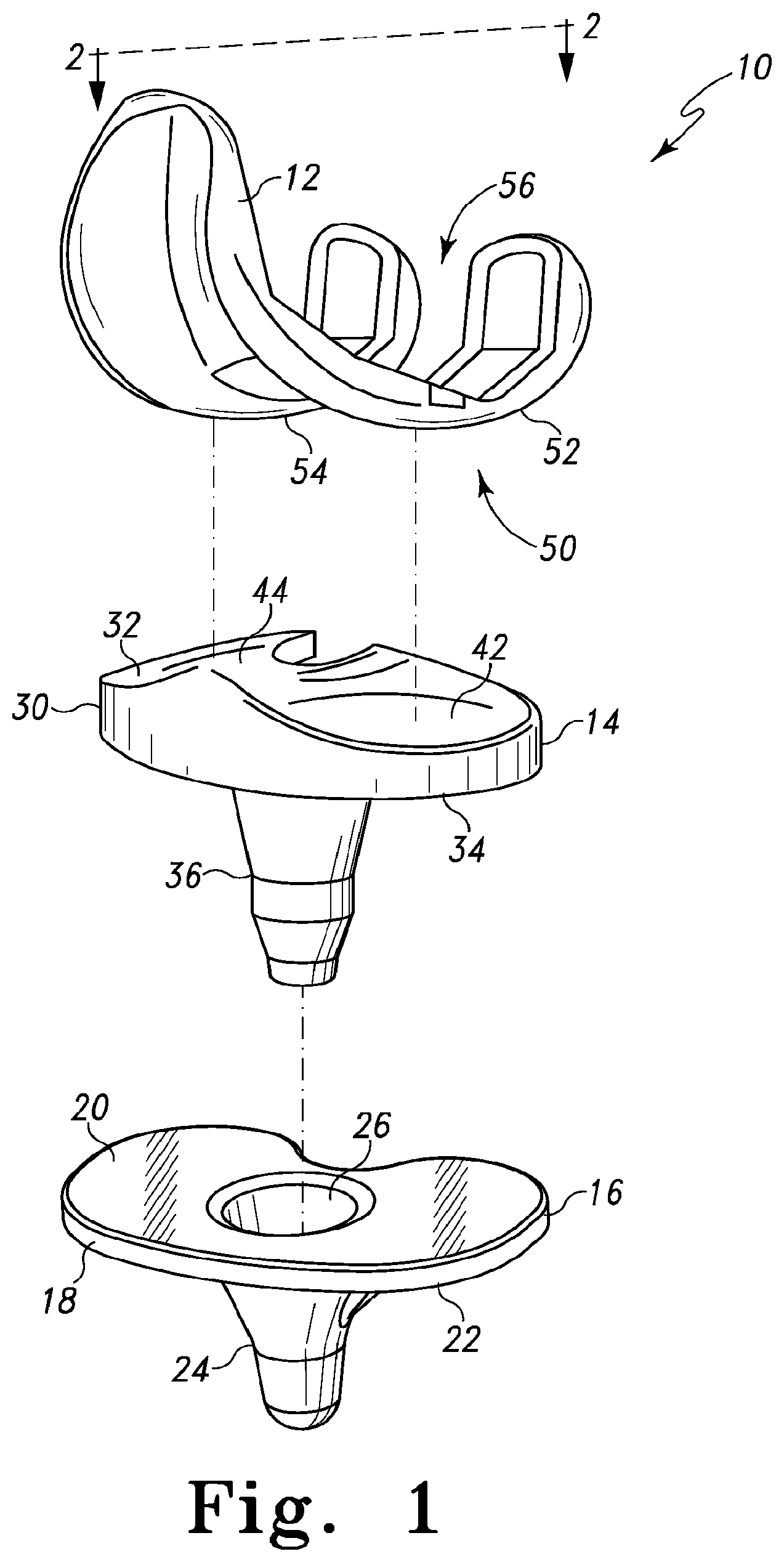
FIG. 1 is an exploded perspective view of one embodiment of an orthopaedic knee prosthesis;
FIG. 2 is an exploded perspective view of another embodiment of an orthopaedic knee prosthesis;
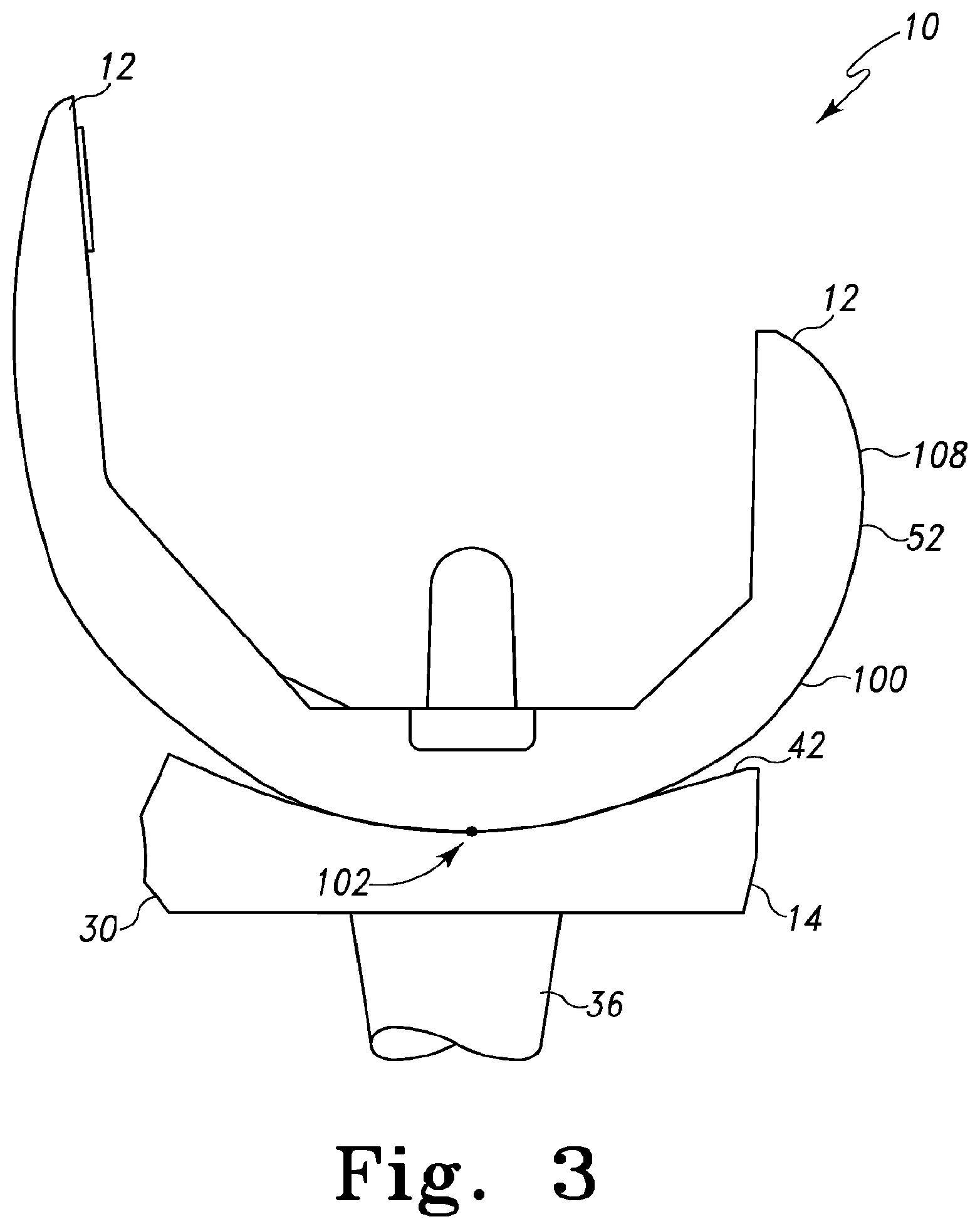
FIG. 3 is a cross-sectional view of one embodiment of a femoral component and tibial bearing of FIG. 1 taken generally along section lines 2-2 and having the femoral component articulated to a first degree of flexion;
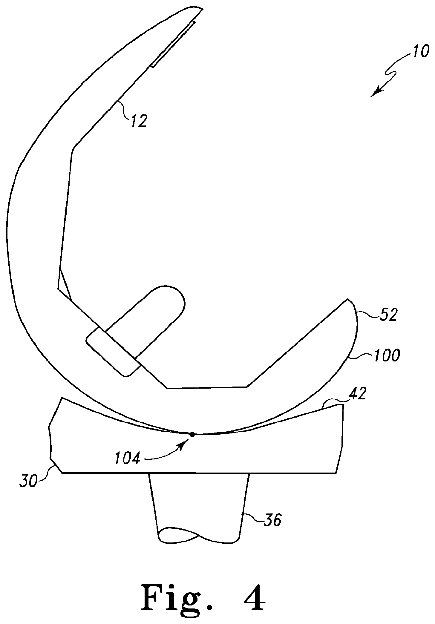
FIG. 4 is a cross-sectional view of a femoral component and tibial bearing of FIG. 3 having the femoral component articulated to a second degree of flexion;
FIG. 5 is a cross-sectional view of a femoral component and tibial bearing of FIG. 3 having the femoral component articulated to a third degree of flexion;
FIG. 6 is a cross-sectional view of another embodiment of the femoral component of FIG. 1;
FIG. 7 is a cross-sectional view of another embodiment of the femoral component of FIG. 1;
FIG. 8 is a graph of the anterior-posterior translation of a simulated femoral component having an increased radius of curvature located at various degrees of flexion;
FIG. 9 is a graph of the anterior-posterior translation of another simulated femoral component having an increased radius of curvature located at various degrees of flexion;
FIG. 10 is a graph of the anterior-posterior translation of another simulated femoral component having an increased radius of curvature located at various degrees of flexion; and
FIG. 11 is a graph of the anterior-posterior translation of another simulated femoral component having an increased radius of curvature located at various degrees of flexion.
DETAILED DESCRIPTION OF THE DRAWINGS
While the concepts of the present disclosure are susceptible to various modifications and alternative forms, specific exemplary embodiments thereof have been shown by way of example in the drawings and will herein be described in detail. It should be understood, however, that there is no intent to limit the concepts of the present disclosure to the particular forms disclosed, but on the contrary, the intention is to cover all modifications, equivalents, and alternatives falling within the spirit and scope of the invention as defined by the appended claims.
Terms representing anatomical references, such as anterior, posterior, medial, lateral, superior, inferior, etcetera, may be used throughout this disclosure in reference to both the orthopaedic implants described herein and a patient's natural anatomy. Such terms have well-understood meanings in both the study of anatomy and the field of orthopaedics. Use of such anatomical reference terms in the specification and claims is intended to be consistent with their well-understood meanings unless noted otherwise.
Referring now to FIG. 1, in one embodiment, an orthopaedic knee prosthesis 10 includes a femoral component 12, a tibial bearing 14, and a tibial tray 16. The femoral component 12 and the tibial tray 16 are illustratively formed from a metallic material such as cobalt-chromium or titanium, but may be formed from other materials, such as a ceramic material, a polymer material, a bio-engineered material, or the like, in other embodiments. The tibial bearing 14 is illustratively formed from a polymer material such as a ultra-high molecular weight polyethylene (UHMWPE), but may be formed from other materials, such as a ceramic material, a metallic material, a bio-engineered material, or the like, in other embodiments.
As discussed in more detail below, the femoral component 12 is configured to articulate with the tibial bearing 14, which is configured to be coupled with the tibial tray 16. In the illustrative embodiment of FIG. 1, the tibial bearing 14 is embodied as a rotating or mobile tibial bearing and is configured to rotate relative to the tibial tray 16 during use. However, in other embodiments, the tibial bearing 14 may be embodied as a fixed tibial bearing, which may be limited or restricted from rotating relative the tibial tray 16.
The tibial tray 16 is configured to be secured to a surgically-prepared proximal end of a patient's tibia (not shown). The tibial tray 16 may be secured to the patient's tibia via use of bone adhesive or other attachment means. The tibial tray 16 includes a platform 18 having a top surface 20 and a bottom surface 22. Illustratively, the top surface 20 is generally planar and, in some embodiments, may be highly polished. The tibial tray 16 also includes a stem 24 extending downwardly from the bottom surface 22 of the platform 18. A cavity or bore 26 is defined in the top surface 20 of the platform 18 and extends downwardly into the stem 24. The bore 26 is formed to receive a complimentary stem of the tibial insert 14 as discussed in more detail below.
As discussed above, the tibial bearing 14 is configured to be coupled with the tibial tray 16. The tibial bearing 14 includes a platform 30 having an upper bearing surface 32 and a bottom surface 34. In the illustrative embodiment wherein the tibial bearing 14 is embodied as a rotating or mobile tibial bearing, the bearing 14 includes a stem 36 extending downwardly from the bottom surface 32 of the platform 30. When the tibial bearing 14 is coupled to the tibial tray 16, the stem 36 is received in the bore 26 of the tibial tray 16. In use, the tibial bearing 14 is configured to rotate about an axis defined by the stem 36 relative to the tibial tray 16. In embodiments wherein the tibial bearing 14 is embodied as a fixed tibial bearing, the bearing 14 may or may not include the stem 22 and/or may include other devices or features to secure the tibial bearing 14 to the tibial tray 16 in a non-rotating configuration.
The upper bearing surface 32 of the tibial bearing 14 includes a medial bearing surface 42 and a lateral bearing surface 44. The medial and lateral bearing surfaces 42, 44 are configured to receive or otherwise contact corresponding medial and lateral condyles of the femoral component 12 as discussed in more detail below. As such, each of the bearing surface 42, 44 has a concave contour.
The femoral component 12 is configured to be coupled to a surgically-prepared surface of the distal end of a patient's femur (not shown). The femoral component 12 may be secured to the patient's femur via use of bone adhesive or other attachment means. The femoral component 12 includes an outer, articulating surface 50 having a pair of medial and lateral condyles 52, 54. The condyles 52, 54 are spaced apart to define an intracondyle opening 56 therebetween. In use, the condyles 52, 54 replace the natural condyles of the patient's femur and are configured to articulate on the corresponding bearing surfaces 42, 44 of the platform 30 of the tibial bearing 14.
The illustrative orthopaedic knee prosthesis 10 of FIG. 1 is embodied as a posterior cruciate-retaining knee prosthesis. That is, the femoral component 12 is embodied as a posterior cruciate-retaining knee prosthesis and the tibial bearing 14 is embodied as a posterior cruciate-retaining tibial bearing 14. However, in other embodiments, the orthopaedic knee prosthesis 10 may be embodied as a posterior cruciate-sacrificing knee prosthesis as illustrated in FIG. 2.
In such embodiments, the tibial bearing 14 is embodied as a posterior stabilizing tibial bearing and includes a spine 60 extending upwardly from the platform 30. The spine 60 is positioned between the bearing surfaces 42, 44 and includes an anterior side 62 and a posterior side 64 having a cam surface 66. In the illustrative embodiment, the cam surface 66 has a substantially concave curvature. However, spines 60 including cam surfaces 66 having other geometries may be used in other embodiments. For example, a tibial bearing including a spine having a substantially "5"-shaped cross-sectional profile, such as the tibial bearing described in U.S. patent application Ser. No. 12/165,582, entitled "Posterior Stabilized Orthopaedic Prosthesis" by Joseph G. Wyss, et al., which is hereby incorporated by reference, may be used in other embodiments.
Additionally, in such embodiments, the femoral component 12 is embodied as a posterior stabilized femoral component and includes an intracondyle notch or recess 57 (rather than an opening 56). A posterior cam 80 (shown in phantom) and an anterior cam 82 are positioned in the intracondyle notch 57. The posterior cam 80 is located toward the posterior side of the femoral component 12 and includes a cam surface 86 configured to engage or otherwise contact the cam surface 66 of the spine 60 of the tibial bearing 14 during flexion.
It should be appreciated that although the orthopaedic knee prosthesis 10 may be embodied as either a posterior cruciate-retaining or a cruciate-sacrificing knee prosthesis, the femoral component 12 and the tibial bearing 14 of the knee prosthesis 10 are discussed below, and illustrated in the remaining figures, in regard to a posterior cruciate-retaining knee prosthesis with the understanding that such description is equally applicable to those embodiments wherein the orthopaedic knee prosthesis 10 is embodied as a posterior cruciate-sacrificing (posterior stabilized) orthopaedic knee prosthesis.
It should be appreciated that the illustrative orthopaedic knee prosthesis 10 is configured to replace a patient's right knee and, as such, the bearing surface 42 and the condyle 52 are referred to as being medially located; and the bearing surface 44 and the condyle 54 are referred to as being laterally located. However, in other embodiments, the orthopaedic knee prosthesis 10 may be configured to replace a patient's left knee. In such embodiments, it should be appreciated that the bearing surface 42 and the condyle 52 may be laterally located and the bearing surface 44 and the condyle 54 may be medially located. Regardless, the features and concepts described herein may be incorporated in an orthopaedic knee prosthesis configured to replace either knee joint of a patient.
Referring now to FIGS. 3-5, the femoral component 12 is configured to articulate on the tibial bearing 14 during use. Each condyle 52, 54 of the femoral component 12 includes a condyle surface 100, which is convexly curved in the sagittal plane and configured to contact the respective bearing surface 42, 44. For example, in one embodiment as shown in FIG. 3, when the orthopaedic knee prosthesis 10 is in extension or is otherwise not in flexion (e.g., a flexion of about 0 degrees), the condyle surface 100 of the condyle 52 contacts the bearing surface 42 (or bearing surface 44 in regard to condyle 54) at one or more contact points 102 on the condyle surface 100.
Additionally, as the orthopaedic knee prosthesis 10 is articulated through the middle degrees of flexion, the femoral component 12 contacts the tibial bearing 14 at one or more contact points on the condyle surface 100. For example, in one embodiment as illustrated in FIG. 4, when the orthopaedic knee prosthesis 10 is articulated to a middle degree of flexion (e.g., at about 45 degrees), the condyle surface 100 contacts the bearing surface 42 at one or more contact points 104 on the condyle surface 100. Similarly, as the orthopaedic knee prosthesis 10 is articulated to a late degree of flexion (e.g., at about 70 degrees of flexion), the condyle surface 100 contacts the bearing surface 42 at one or more contact points 106 on the condyle surface 100 as illustrated in FIG. 5. It should be appreciated, of course, that the femoral component 12 may contact the tibial bearing 14 at a plurality of contact points on the condyle surface 100 at any one particular degree of flexion. However, for clarity of description, only the contact points 102, 104, 106 have been illustrated in FIGS. 3-5, respectively.
The orthopaedic knee prosthesis 10 is configured such that the amount of paradoxical anterior translation of the femoral component 12 relative to the tibial bearing 14 may be reduced or otherwise delayed to a later (i.e., larger) degree of flexion. In particular, as discussed in more detail below, the condyle surface 100 of one or both of the condyles 52, 54 has particular geometry or curvature configured to reduce and/or delay anterior translations and, in some embodiments, promote "roll-back" or posterior translation, of the femoral component 12. It should be appreciated that by delaying the onset of paradoxical anterior translation of the femoral component 12 to a larger degree of flexion, the overall occurrence of paradoxical anterior translation may be reduced during those activities of a patient in which deep flexion is not typically obtained.
In a typical orthopaedic knee prosthesis, paradoxical anterior translation may occur whenever the knee prosthesis is positioned at a degree of flexion greater than zero degrees. The likelihood of anterior translation generally increases as the orthopaedic knee prosthesis is articulated to larger degrees of flexion, particularly in the mid-flexion range. In such orientations, paradoxical anterior translation of the femoral component on the tibial bearing can occur whenever the tangential (traction) force between the femoral component and the tibial bearing fails to satisfy the following equation: T<.mu.N (1)
wherein "T" is the tangential (traction) force, ".mu." is the coefficient of friction of the femoral component and the tibial bearing, and "N" is the normal force between the femoral component and the tibial bearing. As a generalization, the tangential (traction) force between the femoral component and the tibial bearing can be defined as T=M/R (2)
wherein "T" is the tangential (traction) force between the femoral component and the tibial bearing, "M" is the knee moment, and "R" is the radius of curvature in the sagittal plane of the condyle surface in contact with the tibial bearing at the particular degree of flexion. It should be appreciated that equation (2) is a simplification of the governing real-world equations, which does not consider such other factors as inertia and acceleration. Regardless, the equation (2) provides insight that paradoxical anterior translation of an orthopaedic knee prosthesis may be reduced or delayed by controlling the radius of curvature of the condyle surface of the femoral component. That is, by controlling the radius of curvature of the condyle surface (e.g., increasing or maintaining the radius of curvature), the right-hand side of equation (2) may be reduced, thereby decreasing the value of the tangential (traction) force and satisfying the equation (1). As discussed above, by ensuring that the tangential (traction) force satisfies equation (1), paradoxical anterior translation of the femoral component on the tibial bearing may be reduced or otherwise delayed to a greater degree of flexion.
Based on the above analysis, to reduce or delay the onset of paradoxical anterior translation, the geometry of the condyle surface 100 of one or both of the condyles 52, 54 of the femoral component 12 is controlled. For example, in some embodiments, the radius of curvature of the condyle surface 100 is controlled such that the radius of curvature is held constant over a range of degrees of flexion and/or is increased in the early to mid flexion ranges. Comparatively, typical femoral components have decreasing radii of curvatures beginning at the distal radius of curvature (i.e., at about 0 degrees of flexion). However, it has been determined that by maintaining a relatively constant radius of curvature (i.e., not decreasing the radius of curvature) over a predetermined range of degrees of early to mid-flexion and/or increasing the radius of curvature over the predetermined range of degrees of flexion may reduce or delay paradoxical anterior translation of the femoral component 12.
Additionally, in some embodiments, the condyle surface 100 is configured or designed such that the transition between discrete radii of curvature of the condyle surface 100 is gradual. That is, by gradually transitioning between the discrete radii of curvature, rather than abrupt transitions, paradoxical anterior translation of the femoral component 12 may be reduced or delayed. Further, in some embodiments, the rate of change in the radius of curvature of the condyle surface in the early to mid flexion ranges (e.g., from about 0 degrees to about 90 degrees) is controlled such that the rate of change is less than a predetermined threshold. That is, it has been determined that if the rate of change of the radius of curvature of the condyle surface 100 is greater than the predetermined threshold, paradoxical anterior translation may occur.
Accordingly, in some embodiments as illustrated in FIGS. 6-12, the condyle surface 100 of the femoral component 12 has an increased radius of curvature in early to middle degrees of flexion. By increasing the radius of curvature, paradoxical anterior translation may be reduced or delayed to a later degree of flexion. The amount of increase between the radius of curvature R2 and the radius of curvature R3 (see FIGS. 6 and 7), as well as, the degree of flexion on the condyle surface 100 at which such increase occurs has been determined to affect the occurrence of paradoxical anterior translation. As discussed in more detail in the U.S. patent application Ser. No. 12/165,579, entitled "Orthopaedic Femoral Prosthesis Having Controlled Condylar Curvature", which was filed concurrently herewith and is hereby incorporated by reference, multiple simulations of various femoral component designs were performed using the LifeMOD/Knee Sim, version 1007.1.0 Beta 16 software program, which is commercially available from LifeModeler, Inc. of San Clemente, Calif., to analyze the effect of increasing the radius of curvature of the condyle surface of the femoral components in early and mid flexion. Based on such analysis, it has been determined that paradoxical anterior translation of the femoral component relative to the tibial bearing may be reduced or otherwise delayed by increasing the radius of curvature of the condyle surface by an amount in the range of about 0.5 millimeters to about 5 millimeters or more at a degree of flexion in the range of about 30 degrees of flexion to about 90 degrees of flexion.
For example, the graph 200 illustrated in FIG. 8 presents the results of a deep bending knee simulation using a femoral component wherein the radius of curvature of the condyle surface is increased by 0.5 millimeters (i.e., from 25.0 millimeters to 25.5 millimeters) at 30 degrees of flexion, at 50 degrees of flexion, at 70 degrees of flexion, and at 90 degrees of flexion. Similarly, the graph 300 illustrated in FIG. 9 presents the results of a deep bending knee simulation using a femoral component wherein the radius of curvature of the condyle surface is increased by 1.0 millimeters (i.e., from 25.0 millimeters to 26.0 millimeters) at 30 degrees of flexion, at 50 degrees of flexion, at 70 degrees of flexion, and at 90 degrees of flexion. The graph 400 illustrated in FIG. 10 presents the results of a deep bending knee simulation using a femoral component wherein the radius of curvature of the condyle surface is increased by 2.0 millimeters (i.e., from 25.0 millimeters to 27.0 millimeters) at 30 degrees of flexion, at 50 degrees of flexion, at 70 degrees of flexion, and at 90 degrees of flexion. Additionally, the graph 500 illustrated in FIG. 11 presents the results of a deep bending knee simulation using a femoral component wherein the radius of curvature of the condyle surface is increased by 5.0 millimeters (i.e., from 25.0 millimeters to 26.0 millimeters) at 30 degrees of flexion, at 50 degrees of flexion, at 70 degrees of flexion, and at 90 degrees of flexion.
In the graphs 200, 300, 400, 500, the condylar lowest or most distal points (CLP) of the medial condyle ("med") and the lateral condyle ("lat") of the femoral component are graphed as a representation of the relative positioning of the femoral component to the tibial bearing. As such, a downwardly sloped line represents roll-back of the femoral component on the tibial bearing and an upwardly sloped line represents anterior translation of the femoral component on the tibial bearing.
As illustrated in the graphs 200, 300, 400, 500, anterior sliding of the femoral component was delayed until after about 100 degrees of flexion in each of the embodiments; and the amount of anterior translation was limited to less than about 1 millimeter. In particular, "roll-back" of the femoral component on the tibial bearing was promoted by larger increases in the radius of curvature of the condyle surface at earlier degrees of flexion. Of course, amount of increase in the radius of curvature and the degree of flexion at which such increase is introduced is limited by other factors such as the anatomical joint space of the patient's knee, the size of the tibial bearing, and the like. Regardless, based on the simulations reported in the graphs 200, 300, 400, 500, paradoxical anterior translation of the femoral component on the tibial bearing can be reduced or otherwise delayed by increasing the radius of curvature of the condyle surface of the femoral component during early to mid flexion.
Accordingly, referring back to FIGS. 6 and 7, the condyle surface 100 in the sagittal plane is formed in part from a number of curved surface sections 102, 104, 106, 108, the sagittal ends of each of which are tangent to the sagittal ends of any adjacent curved surface section of the condyles surface 100. Each curved surface section 102, 106, 108 is defined by a radius of curvature. In particular, the curved surface section 102 is defined by a radius of curvature R1, the curved surface section 106 is defined by a radius of curvature R3, and the curved surface section 108 is defined by a radius of curvature R4. In addition, as discussed in more detail below, the curved surface section 104 is designed to provide a gradual transition from the first radius of curvature R1 to a second radius of curvature R2. To do so, the curved surface section 104 is defined by a plurality of curved surface sections 110, 120, each of which is defined by a separate radius of curvature R5.
As discussed above, the condyle surface 100 of the femoral component 12 is configured such that the radius of curvature R3 of the curved surface section 106 is greater than the radius of curvature R2 of the curved surface section 104. In one embodiment, the radius of curvature R3 is greater than the radius of curvature R2 by 0.5 millimeters or more. In another embodiment, the radius of curvature R3 is greater than the radius of curvature R2 by 2 millimeters or more. In another embodiment, the radius of curvature R3 is greater than the radius of curvature R2 by 2 millimeters or more. In a particular embodiment, the radius of curvature R3 is greater than the radius of curvature R2 by at least 5 millimeters or more. It should be appreciated, however, that the particular increase of radius of curvature between R2 and R3 may be based on or scaled to the particular size of the femoral component 12 in some embodiments.
Each of the curved surface sections 102, 104, 106, 108 contacts the bearing surface 42 (or 44) of the tibial bearing 14 through different ranges of degrees of flexion. For example, the curved surface section 102 extends from an earlier degree of flexion .theta.1 to a later degree of flexion .theta.2. The curved surface section 104 extends from the degree of flexion .theta.2 to a later degree of flexion .theta.3. The curved surface section 106 extends from the degree of flexion .theta.3 to a later degree of flexion .theta.4.
For example, in one embodiment, the curved surface section 102 may extend from a degree of flexion .theta.1 of about -10 degrees (i.e., 10 degrees of hyperextension) to a degree of flexion .theta.2 of about 5 degrees of flexion. The curved surface section 104 extends from the degree of flexion .theta.2 of about 5 degrees of flexion to a degree of flexion .theta.3 of about 65 degrees of flexion. The curved surface section 106 extends from the degree of flexion .theta.3 of about 65 degrees of flexion to a degree of flexion .theta.4 of about 90 degrees of flexion and the curved surface section 108 extends from the degree of flexion .theta.4 of about 90 degrees of flexion to a degree of flexion .theta.5 of about 104 degrees of flexion.
It should be appreciated, however, that each of the curved surface sections 102, 104, 106, 108 may extend from degrees of flexion different from those discussed above. For example, the particular degrees of flexion through which the curved surface sections 102, 104, 106, 108 extend may be based or otherwise determined based on the type of femoral component 12 (e.g., cruciate-retaining or posterior stabilized), the size of the femoral component 12, and/or the like.
As discussed above, the curved surface section 104 is designed to gradually transition from the radius of curvature R1 to the radius of curvature R2. To do so, in one embodiment as illustrated in FIG. 5, the curved surface section 104 is defined by a plurality of curved surface sections 110. In the illustrative embodiment of FIG. 5, the curved surface section 104 is defined by six curved surface sections 110A, 110B, 110C, 110D, 110E, 110F, but may be defined by or otherwise include more or less curved surface sections 110 in other embodiments. The particular number of curved surface sections 110 used may be based on, for example, the size of the angle subtended by the curved surface section 104.
Each of the curved surface sections 110 of the condyle surface 100 contacts the bearing surface 42 (or 44) of the tibial bearing 14 through different ranges of degrees of flexion. For example, the curved surface section 110A extends from the degree of flexion .theta.2 to a later degree of flexion .theta.C1, the curved surface section 110B extends from the degree of flexion .theta.C1 to a later degree of flexion .theta.C2, the curved surface section 11.theta.C extends from the degree of flexion .theta.C2 to a later degree of flexion .theta.C3, the curved surface section 110D extends from the degree of flexion .theta.C3 to a later degree of flexion .theta.C4, the curved surface section 110E extends from the degree of flexion .theta.C4 to a later degree of flexion .theta.C5, and the curved surface section 110F extends from the degree of flexion .theta.C5 to the later degree of flexion .theta.3.
In the illustrative embodiment of FIG. 6, each of the curved surface sections 110 extend substantially equal degrees of flexion. That is, the degrees of flexion between .theta.2 and .theta.C1, .theta.C1 and .theta.C2, between .theta.C2 and .theta.C3, between .theta.C3 and .theta.C4, between .theta.C4 and .theta.C5, and between .theta.C5 and .theta.3 are substantially equal. In one particular embodiment, each curved surface section 110 extends for about 10 degrees. However, in other embodiments, each curved surface section 110 may extend a greater or lesser amount. In particular, in one embodiment, each curved surface section extend (i.e., subtend an angle) from about 1 degree to about 15 degrees.
Each of the curved surface sections 110 is defined by a radius of curvature R5. That is, the curved surface section 110A is defined by a radius of curvature R5A, the curved surface section 110B is defined by a radius of curvature R5B, the curved surface section 110C is defined by a radius of curvature R5C, the curved surface section 110D is defined by a radius of curvature R5D, the curved surface section 110E is defined by a radius of curvature R5E, and the curved surface section 110F is defined by a radius of curvature R5F. Each radius of curvature R5 is smaller (i.e., has a shorter length) than the anteriorly-adjacent radius of curvature R5. That is, R5F is smaller than R5E, R5E is smaller than R5D, R5D is smaller than R5C, R5C is smaller than R5B, and R5B is smaller than R5A. For example, in one embodiment, each radius of curvature R5 may have a length shorter than the anteriorly-adjacent radius of curvature R5 by an amount in the range of about 0.1 millimeters to about 5 millimeters. However, in other embodiments, each radius of curvature R5 may have a length shorter than the anteriorly-adjacent radius of curvature R5 by an amount greater or less than such values. The particular length of each radius of curvature R5 may be determined based on the particular application, the length of the curved surface section 104, an defined equation, and/or the like.
Referring now to FIG. 7, in another embodiment, the curved surface section 104 may be formed by a plurality of curved surface sections 120, each of which may extend a different amount of degrees (i.e., subtend angles of different sizes). For example, in the illustrative embodiment of FIG. 7, the curved surface section 104 is defined by ten curved surface sections 120A, 120B, 120C, 120D, 120E, 120F, 120G, 120H, 120I, 120J. The curved surface section 120A extends from the degree of flexion .theta.1 to a later degree of flexion .theta.C1, the curved surface section 120B extends from the degree of flexion .theta.C1 to a later degree of flexion .theta.C2, the curved surface section 12.theta.C extends from the degree of flexion .theta.C2 to a later degree of flexion .theta.C3, the curved surface section 120D extends from the degree of flexion .theta.C3 to a later degree of flexion .theta.C4, the curved surface section 120E extends from the degree of flexion .theta.C4 to a later degree of flexion .theta.C5, the curved surface section 120F extends from the degree of flexion .theta.C5 to a later degree of flexion .theta.C6, the curved surface section 120G extends from the degree of flexion .theta.C6 to a later degree of flexion .theta.C7, the curved surface section 120H extends from the degree of flexion .theta.C7 to a later degree of flexion .theta.C8, the curved surface section 120I extends from the degree of flexion .theta.C8 to a later degree of flexion .theta.C9, and the curved surface section 120J extends from the degree of flexion .theta.C9 to the later degree of flexion .theta.3.
As discussed above, each of the curved surface sections 120 extend different degrees of flexion. That is, the degrees of flexion between .theta.2 and .theta.C1, .theta.C1 and .theta.C2, between .theta.C2 and .theta.C3, between .theta.C3 and .theta.C4, between .theta.C4 and .theta.C5, between .theta.C5 and .theta.C6, between .theta.C6 and .theta.C7, between .theta.C7 and .theta.C8, between .theta.C8 and .theta.C9, and between .theta.C9 and .theta.3 are different from each other. In some embodiments, each curved surface section 120 subtends an angle that is less than the angle subtended by the anteriorly-adjacent section 120. For example, in the illustrative embodiment of FIG. 7, the curved surface section 120A extends for about 10 degrees, the curved surface section 120B extends for about 9 degrees, the curved surface section 120C extends for about 8 degrees, the curved surface section 120D extends for about 7 degrees, the curved surface section 120E extends for about 6 degrees, the curved surface section 120F extends for about 5 degrees, the curved surface section 120G extends for about 4 degrees, the curved surface section 120H extends for about 3 degrees, the curved surface section 120I extends for about 2 degrees, and the curved surface section 120J extends for about 1 degree.
Although each curved surface section 120 subtends an angle 1 degree less than the anteriorly-adjacent section 120 in the illustrative embodiment of FIG. 7, the curved surface sections 120 may subtend angles that are less than the anteriorly adjacent section 120 by an amount greater than 1 degree in other embodiments. Additionally, in other embodiments, each curved surface section 120 may subtend an angle that is greater than the angle subtended by the anteriorly-adjacent section 120. For example, each curved surface section 120 may subtend an angle that is greater than the angle subtended by the anteriorly-adjacent section 120 by about 0.5, 1, or more degrees in some embodiments. Further, in some embodiments, each of the curved surface sections 120 may subtend angles of various sizes. That, each curved surface section 120 may be greater than or less than the anteriorly-adjacent curved surface 120 in some embodiments.
The overall shape and design of the condyle surface 100 of the femoral component 12 has been described above in regard to a single condyle 52, 54 of the femoral component 12. It should be appreciated that in some embodiments both condyles 52, 54 of the femoral component 12 may be symmetrical and have similar condyle surfaces 100. However, in other embodiments, the condyles 52, 54 of the femoral component 12 may be asymmetrical. That is, each condyle 52, 54 may have a condyle surface 100 having the features described herein but being asymmetrical to the other condyle 52, 54.
While the disclosure has been illustrated and described in detail in the drawings and foregoing description, such an illustration and description is to be considered as exemplary and not restrictive in character, it being understood that only illustrative embodiments have been shown and described and that all changes and modifications that come within the spirit of the disclosure are desired to be protected.
There are a plurality of advantages of the present disclosure arising from the various features of the devices and assemblies described herein. It will be noted that alternative embodiments of the devices and assemblies of the present disclosure may not include all of the features described yet still benefit from at least some of the advantages of such features. Those of ordinary skill in the art may readily devise their own implementations of the devices and assemblies that incorporate one or more of the features of the present invention and fall within the spirit and scope of the present disclosure as defined by the appended claims.
* * * * *
References
D00000
D00001
D00002
D00003
D00004
D00005
D00006
D00007
D00008
D00009
D00010
D00011
XML
uspto.report is an independent third-party trademark research tool that is not affiliated, endorsed, or sponsored by the United States Patent and Trademark Office (USPTO) or any other governmental organization. The information provided by uspto.report is based on publicly available data at the time of writing and is intended for informational purposes only.
While we strive to provide accurate and up-to-date information, we do not guarantee the accuracy, completeness, reliability, or suitability of the information displayed on this site. The use of this site is at your own risk. Any reliance you place on such information is therefore strictly at your own risk.
All official trademark data, including owner information, should be verified by visiting the official USPTO website at www.uspto.gov. This site is not intended to replace professional legal advice and should not be used as a substitute for consulting with a legal professional who is knowledgeable about trademark law.