Low profile non-symmetrical stent
Brocker , et al.
U.S. patent number 10,729,531 [Application Number 15/160,602] was granted by the patent office on 2020-08-04 for low profile non-symmetrical stent. This patent grant is currently assigned to Cook Medical Technologies LLC. The grantee listed for this patent is COOK MEDICAL TECHNOLOGIES LLC. Invention is credited to David Brocker, Steven J. Charlebois, Timothy A. M. Chuter, William K. Dierking, Alan R. Leewood, Blayne A. Roeder.


View All Diagrams
| United States Patent | 10,729,531 |
| Brocker , et al. | August 4, 2020 |
Low profile non-symmetrical stent
Abstract
A stent for use in a medical procedure having opposing sets of curved apices, where the curved section of one set of apices has a radius of curvature that is greater than the curved section of the other set of apices. One or more such stents may be attached to a graft material for use in endovascular treatment of, for example, aneurysm, thoracic dissection, or other body vessel condition.
| Inventors: | Brocker; David (Carmel, IN), Dierking; William K. (Louisville, KY), Leewood; Alan R. (Lafayette, IN), Chuter; Timothy A. M. (San Francisco, CA), Roeder; Blayne A. (Bloomington, IN), Charlebois; Steven J. (West Lafayette, IN) | ||||||||||
|---|---|---|---|---|---|---|---|---|---|---|---|
| Applicant: |
|
||||||||||
| Assignee: | Cook Medical Technologies LLC
(Bloomington, IN) |
||||||||||
| Family ID: | 1000004961939 | ||||||||||
| Appl. No.: | 15/160,602 | ||||||||||
| Filed: | May 20, 2016 |
Prior Publication Data
| Document Identifier | Publication Date | |
|---|---|---|
| US 20160262869 A1 | Sep 15, 2016 | |
Related U.S. Patent Documents
| Application Number | Filing Date | Patent Number | Issue Date | ||
|---|---|---|---|---|---|
| 14293286 | Jun 2, 2014 | 9345595 | |||
| 12622351 | Nov 19, 2009 | 8740966 | |||
| 12332904 | Dec 11, 2008 | 9180030 | |||
| 61016753 | Dec 26, 2007 | ||||
| Current U.S. Class: | 1/1 |
| Current CPC Class: | A61F 2/86 (20130101); A61F 2/856 (20130101); A61F 2/07 (20130101); A61F 2/915 (20130101); A61F 2002/91558 (20130101); A61F 2002/91516 (20130101); A61F 2220/0016 (20130101); A61F 2/89 (20130101); A61F 2210/0014 (20130101); A61F 2230/0054 (20130101); A61F 2230/0067 (20130101); A61F 2230/0013 (20130101); A61F 2230/005 (20130101); A61F 2220/0075 (20130101); A61F 2002/065 (20130101); A61F 2002/075 (20130101); A61F 2220/005 (20130101); A61F 2002/8486 (20130101) |
| Current International Class: | A61F 2/07 (20130101); A61F 2/856 (20130101); A61F 2/915 (20130101); A61F 2/86 (20130101); A61F 2/06 (20130101); A61F 2/848 (20130101); A61F 2/89 (20130101) |
References Cited [Referenced By]
U.S. Patent Documents
| 5258021 | November 1993 | Duran |
| 5292331 | March 1994 | Boneau |
| 5403341 | April 1995 | Solar |
| 5569295 | October 1996 | Lam |
| 5607468 | March 1997 | Rogers et al. |
| 5630829 | May 1997 | Lauterjung |
| 5674278 | October 1997 | Boneau |
| 5749921 | May 1998 | Lenker et al. |
| 5782904 | July 1998 | White et al. |
| 5843164 | December 1998 | Frantzen et al. |
| 5855601 | January 1999 | Bessler et al. |
| 5906639 | May 1999 | Rudnick et al. |
| 5913897 | June 1999 | Corso et al. |
| 5961546 | October 1999 | Robinson et al. |
| 5993482 | November 1999 | Chuter |
| 6071307 | June 2000 | Rhee et al. |
| 6110198 | August 2000 | Fogarty et al. |
| 6203569 | March 2001 | Wijay |
| 6245102 | June 2001 | Jayaraman |
| 6287315 | September 2001 | Wijeratne et al. |
| 6293966 | September 2001 | Frantzen |
| 6296662 | October 2001 | Caffey |
| 6336937 | January 2002 | Vonesh et al. |
| 6346118 | February 2002 | Baker et al. |
| 6348068 | February 2002 | Campbell et al. |
| 6350277 | February 2002 | Kocur |
| 6368345 | April 2002 | Dehdashtian et al. |
| 6423090 | July 2002 | Hancock |
| 6451051 | September 2002 | Drasler et al. |
| 6471722 | October 2002 | Inoue |
| 6514282 | February 2003 | Inoue |
| 6524335 | February 2003 | Hartley et al. |
| 6539984 | April 2003 | Lam |
| 6551350 | April 2003 | Thornton et al. |
| 6579314 | June 2003 | Lombardi et al. |
| 6582458 | June 2003 | White et al. |
| 6585757 | July 2003 | Callol |
| 6592614 | July 2003 | Lenker et al. |
| 6616689 | September 2003 | Ainsworth et al. |
| 6629994 | October 2003 | Gomez et al. |
| 6635083 | October 2003 | Cheng et al. |
| 6645242 | November 2003 | Quinn |
| 6648911 | November 2003 | Sirhan et al. |
| 6663661 | December 2003 | Boneau |
| 6673102 | January 2004 | Vonesh et al. |
| 6695875 | February 2004 | Stelter et al. |
| 6723116 | April 2004 | Taheri |
| 6740115 | May 2004 | Lombardi et al. |
| 6849088 | February 2005 | Dehdashtian et al. |
| 6860901 | March 2005 | Baker et al. |
| 6878160 | April 2005 | Gilligan et al. |
| 6962604 | November 2005 | Hijlkema |
| 6974471 | December 2005 | Van Schie et al. |
| 7147657 | December 2006 | Chiang et al. |
| 7186263 | March 2007 | Golds et al. |
| 7232459 | June 2007 | Greenberg et al. |
| 7264632 | September 2007 | Wright et al. |
| 7279003 | October 2007 | Berra et al. |
| 7318835 | January 2008 | Berra |
| 7331992 | February 2008 | Randall et al. |
| 7341598 | March 2008 | Davidson et al. |
| 7407509 | August 2008 | Greenberg et al. |
| 7473275 | January 2009 | Marquez |
| 7534258 | May 2009 | Gomez et al. |
| 7615072 | November 2009 | Rust et al. |
| 7722657 | May 2010 | Hartley |
| 7758626 | July 2010 | Kim et al. |
| 7766962 | August 2010 | Quinn |
| 7794492 | September 2010 | Ishimaru et al. |
| 7828837 | November 2010 | Khoury |
| 7887580 | February 2011 | Randall et al. |
| 7927363 | April 2011 | Perouse |
| 8043354 | October 2011 | Greenberg et al. |
| 8128678 | March 2012 | Leewood et al. |
| 8206427 | June 2012 | Ryan et al. |
| 8292943 | October 2012 | Berra et al. |
| 8333799 | December 2012 | Bales et al. |
| 8348994 | January 2013 | Leopold et al. |
| 8394136 | March 2013 | Hartley et al. |
| 8425586 | April 2013 | Leopold et al. |
| 8480725 | July 2013 | Rasmussen et al. |
| 8545549 | October 2013 | Hartley et al. |
| 8574284 | November 2013 | Roeder et al. |
| 8728145 | May 2014 | Chuter et al. |
| 8740966 | June 2014 | Brocker et al. |
| 8992593 | March 2015 | Chuter et al. |
| 9180030 | November 2015 | Brocker et al. |
| 9220617 | December 2015 | Berra |
| 9226813 | January 2016 | Brocker et al. |
| 9226814 | January 2016 | Jensen et al. |
| 9345595 | May 2016 | Brocker et al. |
| 2001/0000188 | April 2001 | Lenker et al. |
| 2002/0016627 | February 2002 | Golds |
| 2002/0022877 | February 2002 | Mueller et al. |
| 2002/0032487 | March 2002 | Dua et al. |
| 2002/0143381 | October 2002 | Gilligan et al. |
| 2002/0177890 | November 2002 | Lenker |
| 2003/0033002 | February 2003 | Dehdashtian et al. |
| 2003/0033003 | February 2003 | Harrison et al. |
| 2003/0050684 | March 2003 | Abrams et al. |
| 2003/0088305 | May 2003 | Van Schie et al. |
| 2003/0120263 | June 2003 | Ouriel et al. |
| 2003/0120331 | June 2003 | Chobotov et al. |
| 2003/0125797 | July 2003 | Chobotov et al. |
| 2003/0130720 | July 2003 | DePalma et al. |
| 2003/0199967 | October 2003 | Hartley |
| 2004/0002751 | January 2004 | Gilligan et al. |
| 2004/0054396 | March 2004 | Hartley et al. |
| 2004/0073289 | April 2004 | Hartley |
| 2004/0093063 | May 2004 | Wright et al. |
| 2004/0106978 | June 2004 | Greenberg et al. |
| 2004/0111146 | June 2004 | McCullagh |
| 2004/0117003 | June 2004 | Ouriel et al. |
| 2004/0117004 | June 2004 | Osborne et al. |
| 2004/0176833 | September 2004 | Pavcnik et al. |
| 2004/0215316 | October 2004 | Smalling |
| 2004/0215319 | October 2004 | Berra et al. |
| 2004/0254625 | December 2004 | Stephens et al. |
| 2005/0033406 | February 2005 | Barnhart et al. |
| 2005/0049674 | March 2005 | Berra et al. |
| 2005/0075730 | April 2005 | Myers et al. |
| 2005/0090834 | April 2005 | Chiang |
| 2005/0102022 | May 2005 | Solovay et al. |
| 2005/0113905 | May 2005 | Greenberg et al. |
| 2005/0119722 | June 2005 | Styrc et al. |
| 2005/0131516 | June 2005 | Greenhalgh |
| 2005/0154446 | July 2005 | Phillips et al. |
| 2005/0159803 | July 2005 | Lad et al. |
| 2005/0222669 | October 2005 | Purdy |
| 2005/0222671 | October 2005 | Schaeffer et al. |
| 2005/0240257 | October 2005 | Ishimaru et al. |
| 2005/0240258 | October 2005 | Bolduc et al. |
| 2005/0273155 | December 2005 | Bahler |
| 2006/0004433 | January 2006 | Greenberg et al. |
| 2006/0004436 | January 2006 | Amarant et al. |
| 2006/0052860 | March 2006 | Gomez et al. |
| 2006/0100695 | May 2006 | Peacock et al. |
| 2006/0129224 | June 2006 | Arbefeuille |
| 2006/0161243 | July 2006 | Fearnot et al. |
| 2006/0184228 | August 2006 | Khoury |
| 2006/0190070 | August 2006 | Dieck et al. |
| 2006/0190075 | August 2006 | Jordan et al. |
| 2006/0247761 | November 2006 | Greenberg et al. |
| 2006/0265054 | November 2006 | Greenhalgh et al. |
| 2006/0267247 | November 2006 | Anukhin et al. |
| 2007/0027525 | February 2007 | Ben-Muvhar |
| 2007/0043425 | February 2007 | Hartley et al. |
| 2007/0055345 | March 2007 | Arbefeuille |
| 2007/0055347 | March 2007 | Arbefeuille |
| 2007/0067016 | March 2007 | Jung |
| 2007/0073388 | March 2007 | Krolik et al. |
| 2007/0100427 | May 2007 | Perouse |
| 2007/0135889 | June 2007 | Moore et al. |
| 2007/0142894 | June 2007 | Moore et al. |
| 2007/0150051 | June 2007 | Menardiere et al. |
| 2007/0162103 | July 2007 | Case et al. |
| 2007/0163668 | July 2007 | Arbefeuille et al. |
| 2007/0168019 | July 2007 | Amplatz et al. |
| 2007/0179592 | August 2007 | Schaeffer |
| 2007/0185560 | August 2007 | Roeder et al. |
| 2007/0191927 | August 2007 | Bowe et al. |
| 2007/0203566 | August 2007 | Arbefeuille et al. |
| 2007/0208256 | September 2007 | Marilla |
| 2007/0219620 | September 2007 | Eells et al. |
| 2007/0219624 | September 2007 | Brown et al. |
| 2007/0225797 | September 2007 | Krivoruhko |
| 2007/0233220 | October 2007 | Greenan |
| 2007/0233223 | October 2007 | Styrc et al. |
| 2007/0244547 | October 2007 | Greenan |
| 2007/0250152 | October 2007 | Xiao et al. |
| 2007/0282433 | December 2007 | Limon et al. |
| 2008/0033527 | February 2008 | Nunez et al. |
| 2008/0039920 | February 2008 | Peacock et al. |
| 2008/0086190 | April 2008 | Ta |
| 2008/0109066 | May 2008 | Quinn |
| 2008/0114441 | May 2008 | Rust et al. |
| 2008/0114445 | May 2008 | Melsheimer et al. |
| 2008/0119943 | May 2008 | Armstrong et al. |
| 2008/0140178 | June 2008 | Rasmussen et al. |
| 2008/0195191 | August 2008 | Luo et al. |
| 2008/0269866 | October 2008 | Hamer et al. |
| 2008/0281399 | November 2008 | Hartley et al. |
| 2008/0319534 | December 2008 | Birdsall et al. |
| 2009/0005856 | January 2009 | Pappas et al. |
| 2009/0043376 | February 2009 | Hamer et al. |
| 2009/0048663 | February 2009 | Greenberg |
| 2009/0090834 | April 2009 | Richter |
| 2009/0105809 | April 2009 | Lee et al. |
| 2009/0138072 | May 2009 | Gendreau |
| 2009/0149946 | June 2009 | Dixon |
| 2009/0171437 | July 2009 | Brocker et al. |
| 2009/0177270 | July 2009 | Agnew et al. |
| 2009/0306763 | December 2009 | Roeder et al. |
| 2010/0268318 | October 2010 | Glynn |
| 2010/0331960 | December 2010 | Clerc et al. |
| 2012/0029624 | February 2012 | Dierking et al. |
| 2012/0239136 | September 2012 | Bruzzi |
| 2012/0323307 | December 2012 | Richter |
| 0960607 | Dec 1999 | EP | |||
| 0686379 | Aug 2000 | EP | |||
| 1372530 | Jan 2004 | EP | |||
| 1372534 | Nov 2006 | EP | |||
| 1839624 | Oct 2007 | EP | |||
| 1545396 | Dec 2008 | EP | |||
| 2005-512675 | May 2005 | JP | |||
| 2005-521471 | Jul 2005 | JP | |||
| 2009-525139 | Jul 2009 | JP | |||
| 772472 | Nov 2007 | KR | |||
| WO1997/21403 | Jun 1997 | WO | |||
| WO02/076340 | Oct 2002 | WO | |||
| WO02/078569 | Oct 2002 | WO | |||
| WO03/034948 | May 2003 | WO | |||
| WO03/053288 | Jul 2003 | WO | |||
| WO03/082153 | Oct 2003 | WO | |||
| WO2004/017867 | Mar 2004 | WO | |||
| WO2004/017868 | Mar 2004 | WO | |||
| WO2005/034810 | Apr 2005 | WO | |||
| WO2005/099628 | Oct 2005 | WO | |||
| WO2006/028925 | Mar 2006 | WO | |||
| WO2007/092276 | Aug 2007 | WO | |||
| WO2007/095283 | Aug 2007 | WO | |||
| WO2007/098937 | Sep 2007 | WO | |||
| WO2008/021556 | Feb 2008 | WO | |||
| WO2008/051543 | May 2008 | WO | |||
| WO2008/066923 | Jun 2008 | WO | |||
| WO2009/020653 | Feb 2009 | WO | |||
| WO2010/024879 | Mar 2010 | WO | |||
| WO2010/062355 | Jun 2010 | WO | |||
Other References
|
Australian Patent Office, Examination Report No. 1 from Australian Application No. 2017201234 dated Oct. 4, 2017, 3 pages. cited by applicant . Japanese Patent Office, Notification of Reasons for Refusal for Japanese Patent Application No. 2017-040328, dated Feb. 27, 2018, pp. 1-6, including English Translation. cited by applicant . First Examination Report for Australian Patent Application No. 2008341104 dated Oct. 16, 2012, 3 pages. cited by applicant . Second Examination Report for Australian Patent Application No. 2008341104 dated Jul. 9, 2013, 3 pages. cited by applicant . Examination Report No. 1 for Australian Patent Application Serial No. 2010322201 dated Jun. 25, 2013, 4 pages. cited by applicant . Examination Report No. 2 for Australian Patent Application Serial No. 2010322201 dated Aug. 7, 2013, 6 pages. cited by applicant . Examination Report No. 1 for AU 2014200561 dated Apr. 27, 2015, 4 pages. cited by applicant . Extended European Search Report for EP12275202 dated Apr. 9, 2013, 8 pgs. cited by applicant . Examination Report for European Patent Application Serial No. 08 864 911.6 dated Aug. 8, 2012, 4 pages. cited by applicant . Examination Report for European Patent Application Serial No. 08 864 911.6 dated Jan. 9, 2013, 4 pages. cited by applicant . Examination Report for European Patent Application Serial No. 10 779 432.3 dated May 4, 2012, 4 pages. cited by applicant . European Search Report for European Patent Application 11174880, dated Jul. 23, 2012, 6 pgs. cited by applicant . Partial Search Report for European Patent Application Serial No. 11 174 880.2 dated Aug. 8, 2012, 5 pages. cited by applicant . Extended Search Report for European Patent Application Serial No. 11 174 880.2 dated Feb. 8, 2013, 9 pages. cited by applicant . Examination Report for European Patent Application Serial No. 11 174 880.2 dated Sep. 2, 2014, 4 pages. cited by applicant . Combined Search and Examination Report for Great Britain Patent Application Serial No. 0920235.9 dated Mar. 16, 2010, 3 pages. cited by applicant . Examination Report for Great Britain Patent Application Serial No. 0920235.9 dated Jun. 14, 2010, 2 pages. cited by applicant . Search Report for Great Britain Patent Application No. 0920327.4 dated Feb. 9, 2011, 1 page. cited by applicant . Office Action for corresponding JP 2014-203749 and translation, dated Sep. 29, 2015, 7 pages. cited by applicant . Office Action Notice of Grounds of Rejection for Japanese Patent Application No. 2010-540640 dated Nov. 20, 2012, 8 pages including English translation. cited by applicant . Office Action Notice of Grounds of Rejection for Japanese Patent Application Serial No. 2010-540640 dated Nov. 5, 2013, 7 pages, including English Translation. cited by applicant . International Preliminary Report on Patentability for PCT/US2010/056673 dated May 22, 2012, 9 pages. cited by applicant . International Search Report for PCT/US2011/056365 dated Jul. 18, 2012, 5 pages. cited by applicant . International Preliminary Report on Patentability for PCT/US2011/056365 dated Apr. 16, 2013, 7 pages. cited by applicant . Non-Final Office Action for U.S. Appl. No. 12/332,904, dated Oct. 4, 2010, 8 pages. cited by applicant . Final Office Action for U.S. Appl. No. 12/332,904, dated May 9, 2011, 11 pages. cited by applicant . Non-Final Office Action for U.S. Appl. No. 12/332,904, dated Nov. 18, 2011, 12 pages. cited by applicant . Final Office Action for U.S. Appl. No. 12/332,904, dated Jan. 3, 2013, 5 pages. cited by applicant . Non-Final Office Action for U.S. Appl. No. 12/332,904, dated Jan. 14, 2015, 5 pages. cited by applicant . Notice of Allowance for U.S. Appl. No. 12/332,904, dated Jul. 6, 2015, 8 pages. cited by applicant . Non-Final Office Action for U.S. Appl. No. 12/472,082, dated Oct. 4, 2010, 8 pages. cited by applicant . Non-Final Office Action for U.S. Appl. No. 12/472,082, dated Jun. 2, 2011, 12 pages. cited by applicant . Non-Final Office Action for U.S. Appl. No. 14/472,082, dated Dec. 2, 2011, 11 pages. cited by applicant . Final Office Action for U.S. Appl. No. 12/472,082, dated Sep. 13, 2012, 14 pages. cited by applicant . Notice of Allowance for U.S. Appl. No. 12/472,082, dated Jun. 21, 2013, 10 pages. cited by applicant . Notice of Allowance for U.S. Appl. No. 12/472,082, dated Aug. 14, 2013, 4 pages. cited by applicant . Non-Final Office Action for U.S. Appl. No. 12/609,553, dated Dec. 20, 2010, 10 pages. cited by applicant . Final Office Action for U.S. Appl. No. 12/609,553, dated Apr. 4, 2011, 11 pages. cited by applicant . Advisory Action for U.S. Appl. No. 12/609,553, dated Jun. 3, 2011, 3 pages. cited by applicant . Non-Final Office Action for U.S. Appl. No. 12/609,553, dated Oct. 11, 2011, 15 pages. cited by applicant . Final Office Action received for U.S. Appl. No. 12/609,553, dated Mar. 9, 2012, 16 pages. cited by applicant . Advisory Action for U.S. Appl. No. 12/609,553, dated May 24, 2012, 5 pages. cited by applicant . Notice of Panel Decision received for U.S. Appl. No. 12/609,553, dated Dec. 26, 2012, 2 pages. cited by applicant . Notice of Allowance received for U.S. Appl. No. 12/609,553, dated Mar. 13, 2013, 10 pages. cited by applicant . Non-Final Office Action for U.S. Appl. No. 12/622,351, dated Oct. 6, 2010, 10 pages. cited by applicant . Final Office Action for U.S. Appl. No. 12/622,351, dated Jun. 10, 2011, 12 pages. cited by applicant . Non-Final Office Action for U.S. Appl. No. 12/622,351, dated Dec. 1, 2011, 13 pages. cited by applicant . Non-Final Office Action for U.S. Appl. No. 12/622,351, dated Jun. 27, 2012, 25 pages. cited by applicant . Non-Final Office Action for U.S. Appl. No. 12/622,351, dated Apr. 3, 2013, 28 pages. cited by applicant . Notice of Allowance for U.S. Appl. No. 12/622,351, dated Sep. 4, 2013, 8 pages. cited by applicant . Notice of Allowance for U.S. Appl. No. 12/622,351, dated Jan. 21, 2014, 7 pages. cited by applicant . Office Action Restriction Requirement for U.S. Appl. No. 12/841,807, dated Feb. 24, 2012, 9 pages. cited by applicant . Non-Final Office Action for U.S. Appl. No. 12/841,807, dated Jun. 7, 2012, 9 pages. cited by applicant . Final Office Action for U.S. Appl. No. 12/841,807, dated Jan. 11, 2013, 9 pages. cited by applicant . Non-Final Office Action for U.S. Appl. No. 12/841,807, dated Jul. 31, 2014, 10 pages. cited by applicant . Notice of Allowance for U.S. Appl. No. 12/841,807, dated Nov. 24, 2014, 7 pages. cited by applicant . Non-Final Office Action for U.S. Appl. No. 12/904,452, dated May 15, 2012, 11 pages. cited by applicant . Final Office Action for U.S. Appl. No. 12/904,452, dated Dec. 19, 2012, 11 pages. cited by applicant . Final Office Action for U.S. Appl. No. 12/904,452, dated May 1, 2014, 11 pages. cited by applicant . Advisory Action for U.S. Appl. No. 12/904,452, dated Jun. 13, 2014, 2 pages. cited by applicant . Notice of Allowance for U.S. Appl. No. 12/904,452, dated Mar. 9, 2015, 5 pages. cited by applicant . Notice of Allowance for U.S. Appl. No. 12/904,452, dated Aug. 27, 2015, 5 pages. cited by applicant . Non-Final Office Action for U.S. Appl. No. 12/945,097, dated Feb. 29, 2012, 14 pages. cited by applicant . Final Office Action for U.S. Appl. No. 12/945,097, dated Dec. 26, 2012, 11 pages. cited by applicant . Non-Final Office Action for U.S. Appl. No. 12/945,097, dated Oct. 6, 2014, 17 pages. cited by applicant . Final Office Action for U.S. Appl. No. 12/945,097, dated Jul. 2, 2015, 10 pages. cited by applicant . Advisory Action for U.S. Appl. No. 12/945,097, dated Dec. 30, 2015, 3 pages. cited by applicant . Non-Final Office Action for U.S. Appl. No. 12/945,097, dated Sep. 8, 2016, 10 pages. cited by applicant . Non-Final Office Action for U.S. Appl. No. 12/946,233, dated Aug. 16, 2012, 18 pages. cited by applicant . Final Office Action for U.S. Appl. No. 12/946,233, dated May 7, 2013, 23 pages. cited by applicant . Non-Final Office Action for U.S. Appl. No. 12/946,233, dated Apr. 25, 2014, 13 pages. cited by applicant . Non-Final Office Action for U.S. Appl. No. 12/946,233, dated Aug. 29, 2014, 13 pages. cited by applicant . Final Office Action for U.S. Appl. No. 12/946,233, dated Feb. 24, 2015, 13 pages. cited by applicant . Notice of Allowance for U.S. Appl. No. 12/946,233, dated Jun. 8, 2015, 11 pages. cited by applicant . Non-Final Office Action for U.S. Appl. No. 12/946,238, dated Feb. 29, 2012, 14 pages. cited by applicant . Final Office Action for U.S. Appl. No. 12/946,238, dated Sep. 12, 2012, 15 pages. cited by applicant . Non-Final Office Action for U.S. Appl. No. 12/946,238, dated Oct. 6, 2014, 12 pages. cited by applicant . Final Office Action for U.S. Appl. No. 12/946,238, dated Jul. 2, 2015, 15 pages. cited by applicant . Advisory Action for U.S. Appl. No. 12/946,238, dated Dec. 30, 2015, 3 pages. cited by applicant . Non-Final Office Action for U.S. Appl. No. 13/335,142, dated Feb. 14, 2013, 16 pages. cited by applicant . Notice of Allowance for U.S. Appl. No. 13/335,142, dated Sep. 23, 2013, 11 pages. cited by applicant . Notice of Allowance for U.S. Appl. No. 13/335,142, dated Jan. 16, 2014, 7 pages. cited by applicant . Non-Final Office Action for U.S. Appl. No. 14/293,286, dated Aug. 5, 2015, 17 pages. cited by applicant . Notice of Allowance for U.S. Appl. No. 14/293,286, dated Jan. 15, 2016, 9 pages. cited by applicant . Non-Final Office Action for U.S. Appl. No. 14/876,429, dated Jun. 30, 2016, 5 pages. cited by applicant . Non-Final Office Action for U.S. Appl. No. 14/952,498, dated Aug. 11, 2016, 8 pages. cited by applicant . Notice of Allowance for U.S. Appl. No. 12/945,097, dated May 8, 2017, 8 pages. cited by applicant . Notice of Allowance for U.S. Appl. No. 12/946,238, dated Jan. 3, 2017, 11 pages. cited by applicant . Notice of Allowance for U.S. Appl. No. 14/876,429, dated Feb. 28, 2017, 9 pages. cited by applicant . Final Office Action for U.S. Appl. No. 14/952,498, dated Mar. 15, 2017, 8 pages. cited by applicant. |
Primary Examiner: Lopez; Leslie
Attorney, Agent or Firm: Brinks Gilson & Lione
Parent Case Text
CROSS-REFERENCE TO RELATED APPLICATIONS
This application is a continuation of U.S. application Ser. No. 14/293,286, filed Jun. 2, 2014, which is a continuation of U.S. application Ser. No. 12/622,351, filed Nov. 19, 2009, now U.S. Pat. No. 8,740,966, issued Jun. 3, 2014, which is a continuation of U.S. application Ser. No. 12/472,082, filed May 26, 2009, now U.S. Pat. No. 8,574,284, issued Nov. 5, 2013, which is a continuation-in-part of Ser. No. 12/332,904, filed Dec. 11, 2008, now U.S. Pat. No. 9,180,030, issued Nov. 10, 2015, which claims the benefit of U.S. Provisional Application Ser. No. 61/016,753, filed Dec. 26, 2007, and also claims priority under 35 U.S.C. .sctn. 119 to Great Britain Patent Application No. GB0920235.9, filed Nov. 18, 2009 and to Great Britain Patent Application No. GB0920327.4, filed Nov. 19, 2009, which are incorporated in their entirety by reference herein. This application is also related to U.S. application Ser. No. 12/841,807, filed Jul. 22, 2010, now U.S. Pat. No. 8,992,593, issued Mar. 31, 2015, and U.S. application Ser. No. 12/904,452, filed Oct. 14, 2010, now U.S. Pat. No. 9,226,813, issued Jan. 5, 2016, and U.S. application Ser. No. 13/335,142, filed Dec. 22, 2011, now U.S. Pat. No. 8,728,145, issued May 20, 2014, and U.S. application Ser. No. 14/876,429, filed Oct. 6, 2015, and U.S. application Ser. No. 14/952,498, filed Nov. 25, 2015, all of which claim priority to U.S. Provisional Application Ser. No. 61/016,753, filed Dec. 26, 2007, all of which are incorporated in their entirety by reference herein.
Claims
We claim:
1. A stent graft comprising: a tube of graft material having a proximal end and a distal end; a plurality of stents attached to the tube of graft material between the proximal and the distal ends; a first stent of the plurality of stents, the first stent comprising a plurality of proximal apices and a plurality of distal apices, where each proximal apex of the first stent comprises a first curved portion and each distal apex of the first stent defines a second curved portion, wherein each of the first curved portions and the second curved portions comprise a radius of curvature, and the radius of curvature of the proximal apices is greater than the radius of curvature of the distal apices; a second stent of the plurality of stents disposed immediately adjacent and distal of the first stent, the second stent comprising a plurality of distal apices and a plurality of proximal apices, where each distal apex of the second stent comprises a first curved portion and each proximal apex of the second stent defines a second curved portion, wherein each of the first curved portions and the second curved portions comprise a radius of curvature, and the radius of curvature of the distal apices is greater than the radius of curvature of the proximal apices; wherein each distal apex of the first stent substantially abuts a proximal apex of the second stent to define an area of unstented graft material that has a perimeter defined by a proximal apex and two struts connecting the proximal apex of the first stent and a distal apex and two struts connecting the distal apex of the second stent, wherein at least one area of unstented graft material comprises an aperture within the area of unstented graft material that is configured to receive a tubular graft therethrough; and wherein the radius of curvature of the proximal apices of the first stent and the radius of curvature of the distal apices of the second stent is from about 4 mm to about 9 mm.
2. The stent graft of claim 1, further comprising a layer of graft material attached to an inner surface of the tube of graft material that forms a passage extending from the aperture toward the proximal end of the stent graft.
3. The stent graft of claim 1, wherein the radius of curvature of the distal apices of the first stent and the radius of curvature of the proximal apices of the second stent is from about 0.5 mm to about 1.5 mm.
4. The stent graft of claim 1, wherein a ratio of the radius of curvature of the proximal apices of the first stent to the radius of curvature of the distal apices of the first stent is between about 2.6:1 to about 18:1.
5. The stent graft of claim 4, wherein a ratio of the radius of curvature of the distal apices of the second stent to the radius of curvature of the proximal apices of the second stent is between about 2.6:1 to about 18:1.
6. The stent graft of claim 1, wherein a ratio of the radius of curvature of the distal apices of the second stent to the radius of curvature of the proximal apices of the second stent is between about 2.6:1 to about 18:1.
7. The stent graft of claim 1, further comprising a second area of unstented graft material having an aperture in the second area of unstented graft material wherein the aperture of the second area of unstented graft material is configured to receive a second tubular graft therethrough.
8. The stent graft of claim 1, wherein the proximal apices of the first stent have a rounded inner radius.
9. The stent graft of claim 8, wherein the aperture is disposed within the rounded inner radius of a proximal apex of the first stent.
10. The stent graft of claim 9, further comprising a second aperture disposed within a rounded inner radius of a second proximal apex of the first stent, wherein the second aperture is configured to receive a second tubular graft therethrough.
11. The stent graft of claim 1, wherein the radius of curvature of the distal apices of the first stent and the radius of curvature of the proximal apices of the second stent is 1 mm, and wherein the radius of curvature of the proximal apices of the first stent and the radius of curvature of the distal apices of the second stent is 6 mm.
12. A stent graft comprising: a tube of graft material having a proximal end and a distal end; a plurality of stents attached to the tube of graft material between the proximal and the distal ends; a first stent of the plurality of stents, the first stent comprising a plurality of proximal apices and a plurality of distal apices, where each proximal apex comprises a first curved portion and each distal apex defines a second curved portion, wherein each of the first curved portions and the second curved portions comprises a radius of curvature, and the radius of curvature of the proximal apices is greater than the radius of curvature of the distal apices, and a ratio of the radius of curvature of the proximal apices to the radius of curvature of the distal apices is 6:1; a second stent of the plurality of stents disposed immediately adjacent and distal of the first stent, the second stent comprising a plurality of distal apices and a plurality of proximal apices, where each distal apex of the second stent comprises a first curved portion and each proximal apex of the second stent defines a second curved portion, wherein each of the first curved portions and the second curved portions comprise a radius of curvature, and the radius of curvature of the distal apices of the second stent is greater than the radius of curvature of the proximal apices of the second stent, and a ratio of the radius of curvature of the distal apices of the second stent to the radius of curvature of the proximal apices of the second stent is 6:1; wherein each distal apex of the first stent substantially abuts a proximal apex of the second stent to define an area of unstented graft material that has a perimeter defined by a proximal apex and two struts connecting the proximal apex of the first stent and a distal apex and two struts connecting the distal apex of the second stent, wherein at least one area of unstented graft material comprises an aperture within the area of unstented graft material that is configured to receive a tubular graft therethrough; and wherein the radius of curvature of the proximal apices of the first stent and the radius of curvature of the distal apices of the second stent is from about 4 mm to about 9 mm.
13. The stent graft of claim 12, further comprising a second area of unstented graft material having an aperture in the second area of unstented graft material wherein the aperture of the second area of unstented graft material is configured to receive a second tubular graft therethrough.
14. The stent graft of claim 12, wherein the proximal apices of the first stent have a rounded inner radius.
15. The stent graft of claim 14, wherein the aperture is disposed within the rounded inner radius of a proximal apex of the first stent.
Description
FIELD OF THE INVENTION
The present invention relates generally to stents for use in body vessels to treat medical conditions. In particular, this invention relates to an asymmetric stent having opposing sets of curved apices, where the curved section of one set of apices has a radius of curvature that is greater than the curved section of the other set of apices, and may present a lower profile, better compliance with irregular vascular geometry, and higher sealing forces than conventional stents.
BACKGROUND
Stents may be inserted into an anatomical vessel or duct for various purposes. Stents may maintain or restore patency in a formerly blocked or constricted passageway, for example, following a balloon angioplasty procedure. Other stents may be used for different procedures, for example, stents placed in or about a graft have been used to hold the graft in an open configuration to treat an aneurysm. Additionally, stents coupled to one or both ends of a graft may extend proximally or distally away from the graft to engage a healthy portion of a vessel wall away from a diseased portion of an aneurysm to provide endovascular graft fixation.
Stents may be either self-expanding or balloon-expandable, or they can have characteristics of both types of stents. Various existing self-expanding and balloon-expandable stent designs and configurations comprise generally symmetrical end regions including one or more apices formed of nitinol or another alloy wire formed into a ring. The apices commonly comprise relatively acute bends or present somewhat pointed surfaces, which may facilitate compression of the stent to a relatively small delivery profile due to the tight bend of the apices. Although having this advantage, in some situations, such relatively acute or pointed apices may be undesirable, in particular in vessel anatomies that are curved or tortuous such as, for example, the thoracic aorta.
The thoracic aorta presents a challenging anatomy for stent grafts used to treat thoracic aneurysms or dissections. The thoracic aorta comprises a curve known as the aortic arch, which extends between the ascending thoracic aorta (closet to the heart) and the descending thoracic aorta (which extends toward the abdominal aorta). Thoracic stent grafts are used to exclude thoracic aortic aneurysms. A stent graft's ability to conform to the tortuous anatomy of the aortic arch is a major concern. Current designs sometimes lack the desired sealing ability at the proximal end of the stent graft (closest to the heart). Also, current thoracic devices present a relatively large profile which, with some patients' anatomies may be problematic. Finally, many current stents have relatively acute points that may prevent them from being used in the aortic arch for fear of undesirable interaction with the artery wall after an extended amount of time in the patient.
Therefore, a generally nonsymmetrical stent having at least one relatively rounded apex that is less invasive in an expanded state than stents with more acute apices may alleviate the above problems, while providing an improved compliance to the aortic arch and increased radial force if used as a sealing and/or alignment stent, as well as a desirable ability to be crimped to a readily introducible diameter.
As one particular example, type-A thoracic aortic dissection (TAD-A) is a condition in which the intimal layer of the ascending thoracic aorta develops a tear, allowing blood to flow into the layers of the aortic wall, causing the development of a medial or subintimal hematoma. TAD-A is associated with a strikingly high mortality rate (about one-fourth to one-half of victims die within the first 24-48 hours). The only current treatment for TAD-A is open surgery, where the chest is opened, the aorta is clamped, and a vascular prosthesis is sewn in place. Operative mortality rate for this procedure may be around 10%. Endovascular treatment of TAD-B (which affects the descending thoracic aorta) has been effective in reducing short-term and longer term mortality. Therefore, it is desirable to provide an endovascular device configured to address the anatomic challenges of the thoracic aorta.
SUMMARY
The present invention relates generally to stents for use in body vessels to treat medical conditions. In particular, this invention relates to a stent having opposing sets of curved apices, where the curved section of one set of apices has a radius of curvature that is greater than the curved section of the other set of apices, and may present a lower profile than conventional stents. This configuration presents an asymmetrical stent. Specifically, embodiments of the presently-presented stent may maintain a low profile while improving compliance with highly tortuous anatomy (such as, for example, that found in the region of the thoracic aorta and particularly the aortic arch) while providing improved radial sealing force compared to some current devices. In another aspect, the presently-presented stent may provide support and spacing within the larger context of a stent or stent-graft device that will allow, for example, placement of ancillary stents and/or stent-grafts.
In one example, the present invention may include a stent that includes at least one proximal apex and at least one distal apex connected with the proximal apices by a plurality of generally straight portions; where each proximal apex includes a first curved portion and each distal apex comprises a second curved portion; where the first curved portion and the second curved portion each includes at least one radius of curvature, and the radius of curvature of at least one of the proximal apices is greater than the radius of curvature of at least one of the distal apices.
In another example, the present invention may include at least one wire formed into stent including a ring of alternating opposed, generally curved apices where a radius of curvature of a plurality of the apices in a first direction is greater than a radius of curvature of the apices in an opposite direction.
Advantageously, the rounded apices may provide atraumatic contact with a vessel, while the combination of more rounded and less rounded apices provides for a low-profile stent that includes desirable compressibility during introduction and desirable compliance and sealing profiles when deployed in a vessel.
BRIEF DESCRIPTION OF THE DRAWINGS
The invention can be better understood with reference to the following drawings and description. The components in the figures are not necessarily to scale, emphasis instead being placed upon illustrating the principles of the invention. Moreover, in the figures, like referenced numerals designate corresponding parts throughout the different views.
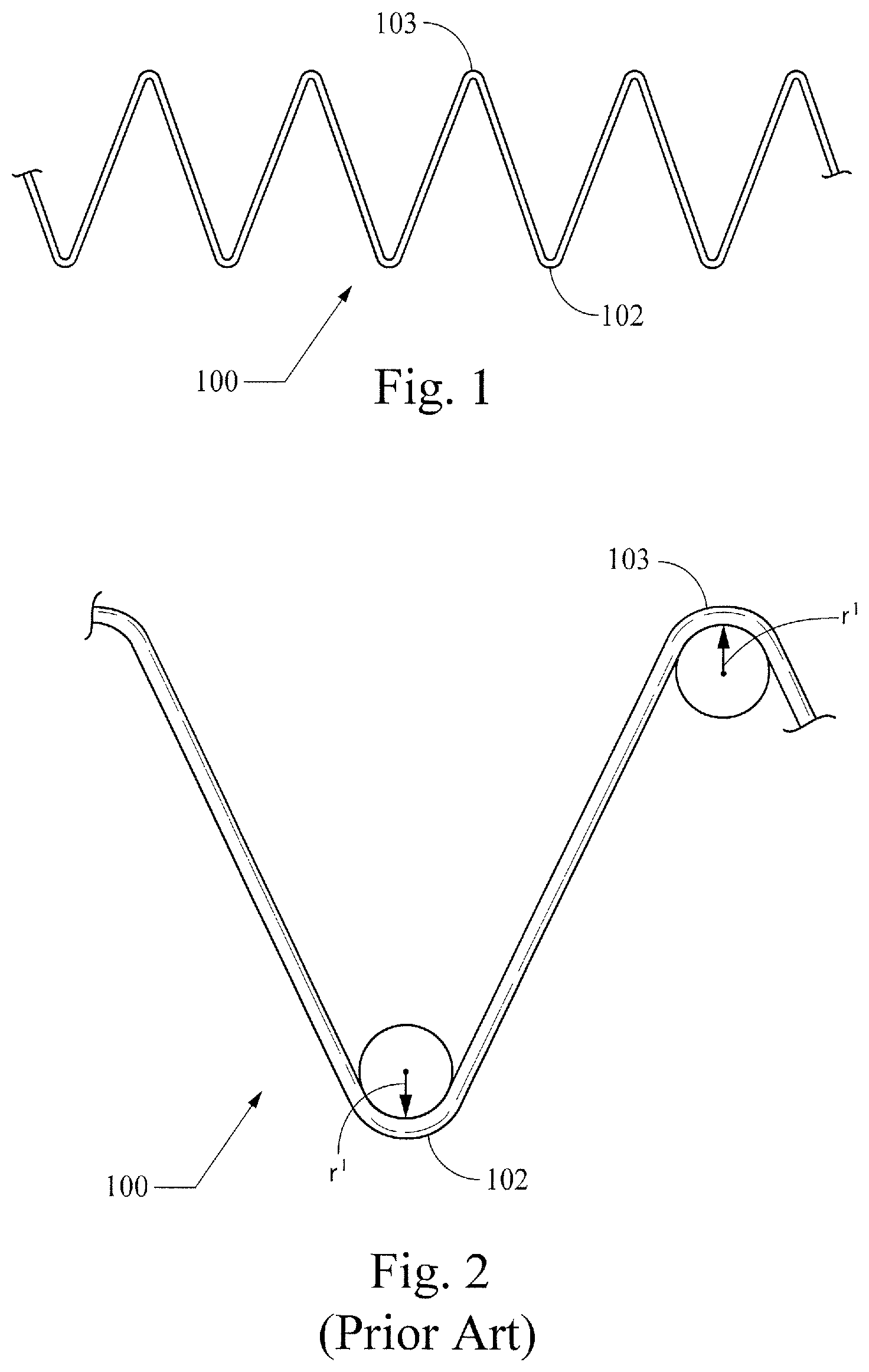
FIGS. 1-3 show different views of a symmetrical stent;
FIG. 4 depicts an example of an asymmetric stent;
FIG. 5 diagrammatically illustrates the asymmetrical radii of curvature of the stent of FIG. 4;
FIG. 6 shows the stent of FIG. 4 in a simulated artery;
FIG. 7 depicts another example of an asymmetric stent;
FIG. 8 diagrammatically illustrates the asymmetrical radii of curvature of yet another example of a stent;
FIG. 9 shows the stent of FIG. 8 in a simulated artery;
FIG. 10 shows an end view of still another example of an asymmetric stent;
FIG. 11 shows a side view of the stent of FIG. 10;
FIG. 12 is a top perspective view of the stent of FIG. 10;
FIG. 13 shows the stent of FIG. 10 in a simulated artery;
FIG. 14 is a partial perspective of a stent-graft incorporating the stent of FIG. 10;
FIG. 15 illustrates a side view of the stent-graft of FIG. 14;
FIGS. 16-18 show a stent-graft with side branches; and
FIG. 19 is a side view of a stent-graft device configured for endovascular treatment of a thoracic aorta dissection.
DETAILED DESCRIPTION OF THE PREFERRED EXAMPLES
The present invention relates generally to stents for use in body vessels to treat medical conditions. In particular, this invention relates to a novel asymmetric stent having opposing sets of curved apices, where the curved section of one set of apices has a radius of curvature that is greater than the curved section of the other set of apices, and may present a lower profile than conventional stents. The lower profile may present advantages for use in patients with particularly tortuous or small-diameter vessels.
In the present application, the term "proximal" refers to a direction that is generally closest to the heart during a medical procedure, while the term "distal" refers to a direction that is furthest from the heart during a medical procedure. Reference throughout is made to proximal and distal apices, but those of skill in the art will appreciate that the proximal-distal orientation of stents of the present invention may be reversed without exceeding the scope of the present invention.
As shown in FIGS. 4-15, this novel stent is not symmetrical like many commercially available stents, in that the radius of curvature of the opposing proximal and distal apices is different between the top and bottom of the stent. The stents may be attached to either end of a stent graft to provide sealing and may be used internally or externally to the graft material to provide support to the graft.
The asymmetric stent may be configured such that, when used with a graft, it will provide a sufficiently strong radial force at the graft's end openings to hold the graft material open against the artery wall. Also, the stent is intended to be short in length so that the graft will include flexibility sufficient to accommodate a patient's anatomy. This combination of flexibility and strong radial force provides an improved seal between the graft and artery wall. In addition, enhanced flexibility is provided as well, particularly when one or more stents are used to provide short segments and better accommodate curves.
FIG. 1 shows a conventional stent 100, which has symmetrical apices 102, 103. Specifically, the proximal apices 102 and the distal apices 103 all have generally the same radii of curvature (r.sup.1), which is illustrated in graphic form in FIG. 2. FIG. 3 is adapted from an FEA contour simulation and shows the stent 100 in a simulated artery 110, where the stent 100 is 20% oversized. The proximal and distal apices 102, 103 (circled) exert little or no pressure against the artery wall 110, while an intermediate region 107 exerts a higher pressure to provide--in one example--a total radial sealing force of 0.178 lbf. This configuration may be crimped to 18 Fr (e.g., for introduction via a catheter), with a maximum bend strain in the apices 102, 103 of about 5.8%. When using, for example, a typical NiTi wire for the stent, it is desirable not to exceed 10-12% strain to avoid increased risk of deforming the wire or adversely affecting its durability.
FIGS. 4-7 show a first example of a non-symmetrical stent 200, which is formed as a wire ring that has non-symmetrical proximal and distal generally curved apex portions (apices) 202, 203 separated from each other by intermediate generally straight portions. Specifically, the distal apices 203 all have generally the same radii of curvature (r.sup.d) as each other, but the distal apices' radii of curvature are different from those of the proximal apices 202 (r.sup.p). The distal apices 203 (which may be attached to and generally covered by graft material in a stent graft as described below with reference to FIGS. 14-15) are generally narrowly rounded in a manner not dissimilar from a traditional z-stent, but the proximal apices 202 are more broadly rounded. The difference in the proximal and distal apices 202, 203 is illustrated in graphic form in FIG. 5. In the illustrated example, the rounded proximal apices 202 have a radius of curvature of 6.0 mm, while the narrower distal apices 202 have a radius of curvature of 1.0 mm. In certain examples of non-symmetrical stents of the present invention, the radius of curvature of the rounded proximal apices (measured in the manner shown in FIG. 5) may be from about 4 mm to about 9 mm, and the radius of curvature of the narrower distal apices may be from about 0.5 mm to about 1.5 mm.
In these and other examples, the ratio of the proximal apices' radius of curvature to the distal apices' radius of curvature may be about 2.6:1 to about 18:1, and desirably may be about 6:1. The outer circumference of the stent 200 preferably is generally consistent such that, in this configuration, a solid outer face around the stent 200 would form a cylinder, although the stent will most preferably provide compliance with a surface less smooth than a cylinder.
FIG. 6 is adapted from an FEA contour simulation and shows the stent 200 in a simulated artery 210, where the stent 200 is 20% oversized. The proximal and distal apices 202, 203 (circled) exert little or no pressure against the artery wall 210, while an intermediate region 204 (boxed) exerts a greater pressure to provide--in the illustrated example--a total radial sealing force of about 0.160 lbf. This configuration may be crimped to 18 Fr, with a maximum bend strain in the apices 202, 203 of about 6.5%.
FIG. 7 shows another non-symmetrical stent embodiment 250 that is very similar to the embodiment of FIGS. 4-6, but which has a shorter proximal-distal length. Each of the examples shown in FIGS. 4-7 may be manufactured in substantially the same manner as current z-stents, with a modification only of forming the proximal apices to include a greater radius of curvature than the distal apices.
FIGS. 8-9 illustrate another example of a non-symmetrical stent 300, which has a proximal "rounded roof shape" profile rather than the generally semicircular profile of the examples described above with reference to FIGS. 4-7. The profile of each proximal apex 302 includes a central fillet 302a and a pair of symmetrically opposed shoulder fillets 302b that may be generally equidistant from the central fillet 302a, or that may be disposed at varied distances therefrom. For the proximal apices of the stent 300, the central fillets 302a each have a radius of curvature of 1.0 mm, and the shoulder fillets 302b each have a fillet radius of curvature of 0.5 mm. The distal apices 304 have a radius of curvature of 1.0 mm. In another example having the rounded roof shape configuration (not shown), the central and shoulder fillets of proximal apices may each have the same radius of curvature such as, for example, 0.5 mm each, with distal apices also having a 0.5 mm radius of curvature. In other examples, the central and shoulder fillets 302a, 302b may each have a radius of curvature from about 0.5 mm to about 5 mm, and the distal apices may each have a radius of curvature of about 0.5 mm to about 1.5 mm. In another example having the rounded roof shape configuration (not shown), the ratio between the radii of curvature of the central and each shoulder fillet of the proximal apices may be about 3:1. FIG. 8 also shows three spans useful for describing desirable proportions in stent embodiments: "x" indicates the distance between the apical extremities of the shoulder fillets 302b, "y" indicates the distance between the tips of the distal apices 304, and "z" indicates the distance along a longitudinal axis between the tip of the distal apices 304 and the apical extremity of the proximal fillet 302a. Desirable embodiments may include an x:y ratio of about 1:3 to about 7:8 and a y:z ratio of about 1:1 to about 3:1. In yet another example (not shown), the filleted apices of this example may be combined with the generally semicircular apices of the example described with reference to FIGS. 4-7.
FIG. 9 is adapted from an FEA contour simulation and shows the stent 300 in a simulated artery 310, where the stent 300 is 20% oversized. The proximal and distal apices 302, 304 exert little or no pressure against the artery wall 310, while an intermediate region exerts a greater pressure to provide--in the illustrated example--a total radial sealing force of about 0.420 Ibf. This configuration may be crimped to 18 Fr, with maximum bend strains in the apices that may be less than about 9% and preferably are less than about 10-12%. The greater radial sealing force of this example may provide advantages for stent placement and retention in certain circumstances as compared to existing z-stents.
FIGS. 10-13 illustrate another example of a non-symmetrical stent 400, which has an expanded "flower configuration" as shown in FIG. 10. Specifically, when the stent 400 is in an expanded configuration, the circumference around the proximal more-rounded apices 402 is greater than the circumference around the distal less-rounded apices 404, which is shown most clearly in FIGS. 11-14. In this configuration a solid outer face around an expanded stent 400 would form a frustum of a cone. This configuration may be manufactured in the same manner as the examples described above with reference to FIGS. 4-7 (i.e., producing a stent with a generally uniform outer circumference), with an added step that may include drawing the distal apices 404 into a smaller circumference upon suturing them to a smaller diameter graft material. Alternatively, or in addition, the stent 400 may be heat-set to impose the desired shape.
FIG. 13 is adapted from an FEA contour simulation and shows the stent 400 in a simulated artery 410, where the stent 400 is 20% oversized. Surprisingly, the contour of pressure distribution along proximal and distal apices 402, 404 as well as an intermediate region is generally uniform throughout the stent circumference. The illustrated configuration provides a total radial sealing force of about 0.187 lbf. This property of generally uniform pressure distribution may provide advantages in certain applications of providing a seal and/or presenting less abrasion of a vessel wall through graft material as compared to stents with less uniform pressure distribution.
FIGS. 14-15 show two different views of a stent graft 500 using a stent example 400 of the present invention described above with reference to FIGS. 10-13. The stent graft 500 is shown in an expanded state and may be configured for use in treating a thoracic aortic aneurysm. The stent 400 is disposed at the proximal end of a generally cylindrical graft sleeve 502, to which its distal apices 404 are secured by sutures 504. The stent graft 500 also includes a series of z-stents 510a-d disposed distally from the stent 400. The first z-stent 510a is attached to the inner circumference of the graft 502, and the other z-stents 510b-510d are attached to the outer diameter of the graft 502. The proximal end of the stent 400 extends beyond the proximal end of the graft in a manner that may facilitate anchoring the graft in a vessel of a patient (e.g., a blood vessel).
The rounded points on the stent may protrude from the graft material only a small amount as is shown in FIGS. 14-15. In this example, only a small portion of the bare wire will be exposed to the artery wall. These unique (larger radii) rounded points are far less likely to perforate the artery wall than sharper points of a different stent configuration. Advantageously, this asymmetric stent design will maximize the efficacy of the seal while preserving the condition of the artery wall. Specifically, the narrower stent apices will provide for desirable radial expansion/sealing force, and the broader rounded apices will provide for a desirably atraumatic contact with an artery wall. This may be enhanced by a flared configuration effected by the relative positioning of a first generally circular outer profile formed by the narrower apices 404 and a second generally circular outer profile formed by the broader apices 402. As shown in FIGS. 14-15, the second generally circular outer profile formed by the broader apices 402 has a greater outer diameter than the first generally circular outer profile formed by the narrower apices 404, which are attached to the tube of graft material 502. It will be appreciated that an opposite end of the stent graft 500 may be constructed without a stent 400, or including a stent 400 attached to the tube of graft material 502.
FIGS. 16-18 show a stent-graft embodiment 600 that includes a non-symmetrical stent 602 having more broadly rounded proximal apices 604 and more narrowly rounded distal apices 606. The stent 602 is attached by sutures to the inner surface (not shown) or outer surface of a generally columnar graft 610, which includes other stents 608. A second layer of graft material 612 is also attached to the inner circumference of the graft 610 midway down its length and extends proximally through the inner circumference of the stent 602.
As shown in the end view of FIG. 17, this construction provides a passage for branch structures 614 (that may be embodied, for example, as tubular or non-tubular stents, stent-grafts, shown here for the sake of illustration as generic tubular structures), which pass through the passage formed between the two layers 610, 612 and through an aperture 611 in the graft 610. The tubular structures 614 will advantageously be disposed generally transversely through the inner radius of the more broadly rounded proximal apices 604 of the stent 602, which provides atraumatic columnar support for the graft 610 as well as an anchor for the tubular structures 614. The stent-graft 600 may be particularly useful for treatment of an abdominal aortic aneurysm (AAA) that is immediately adjacent to, or that goes across, the renal arteries such that it has a short neck and lacks a contact area that is sufficient to create an effective proximal seal and avoid the proximal Type I endoleaks that may occur with some currently-available AAA stent-grafts. Those of skill in the art will appreciate that the stent-graft 600 will allow general occlusion of the AAA, while providing patent passage through the descending aorta and from the aorta to the renal arteries. Specifically, a stent-graft configured in the manner of the stent-graft embodiment 600, which includes a modular design that may include branch stents and/or stent-grafts, will allow a seal to be formed above the renal arteries and below the celiac and superior mesenteric arteries. Also, as shown in FIG. 16, a second non-symmetrical stent 622 may be placed adjacent the first non-symmetrical stent 602 in an opposite orientation that will provide additional atraumatic support for the branching tubular structures 614.
FIG. 19 shows a stent-graft device 700 configured for endovascular treatment of a thoracic aorta dissection. The device 700 includes a non-symmetrical alignment stent 702 attached to a first end of a tubular graft material 704. A sealing stent 706 is attached in the central lumenal graft space proximate the alignment stent 702. The sealing stent 706 preferably is configured with a high radial force to promote efficacious sealing of the graft material 704 against a vessel wall. A body stent 708 configured here as a z-stent is disposed on the exterior of the graft material 704 and preferably is configured to provide longitudinal and circumferential stability/columnar support for the graft material of the device 700, such that it will conform to the vasculature and resist buckling when deployed in torturous anatomy such as the ascending thoracic aorta. A bare cannula stent 710 (such as, for example, a cut nitinol stent) is attached in the tubular graft material 704 at the opposite end from the alignment stent 702. This cannula stent 710 preferably is a conformable kink-resistant stent that provides distal sealing and migration-resistance. In a deployment of the device 700 to treat an aortic dissection, the alignment stent 702 preferably will be disposed proximal (nearer the heart) relative to the vessel tear, with the graft material traversing the tear in a manner generally sealing it from blood flow. And, the distal cannula stent 710 will help conform to the vasculature and retain a seal for treatment of the dissection. One or more of the sealing stent 706, body stent 708, and bare stent 710 may include one or more barbed projections configured to help anchor the device 700.
Stent examples of the present invention may be constructed of NiTi alloys or other materials presently known or yet to be developed, all within the scope of the present invention. The stents preferably are made from Nitinol wire and will therefore be MRI compatible. In another preferable embodiment, a stent may be made from a laser-cut Nitinol cannula, effectively rendering it a seamless or nearly-seamless wire-like construction. Nitinol's superelastic properties will facilitate the stents ability to be crimped down into a low profile delivery system.
Although various examples of the invention have been described, the invention is not to be restricted except in light of the attached claims and their equivalents. Moreover, the advantages described herein are not necessarily the only advantages of the invention and it is not necessarily expected that every example of the invention will achieve all of the advantages described. Different embodiments not expressly described herein including those with features combined in a different manner than expressly illustrated herein may be practiced within the scope of the present invention. For at least these reasons, this narrative description should not be construed as defining the invention; rather, the claims set forth and define the present invention.
* * * * *
D00000
D00001
D00002
D00003
D00004
D00005
D00006
D00007
D00008
D00009
D00010
D00011
XML
uspto.report is an independent third-party trademark research tool that is not affiliated, endorsed, or sponsored by the United States Patent and Trademark Office (USPTO) or any other governmental organization. The information provided by uspto.report is based on publicly available data at the time of writing and is intended for informational purposes only.
While we strive to provide accurate and up-to-date information, we do not guarantee the accuracy, completeness, reliability, or suitability of the information displayed on this site. The use of this site is at your own risk. Any reliance you place on such information is therefore strictly at your own risk.
All official trademark data, including owner information, should be verified by visiting the official USPTO website at www.uspto.gov. This site is not intended to replace professional legal advice and should not be used as a substitute for consulting with a legal professional who is knowledgeable about trademark law.