Cooling via a sleeve connector
Leigh , et al.
U.S. patent number 10,721,843 [Application Number 15/565,945] was granted by the patent office on 2020-07-21 for cooling via a sleeve connector. This patent grant is currently assigned to Hewlett Packard Enterprise Development LP. The grantee listed for this patent is Hewlett Packard Enterprise Development LP. Invention is credited to Kevin Leigh, George Megason.


View All Diagrams
| United States Patent | 10,721,843 |
| Leigh , et al. | July 21, 2020 |
Cooling via a sleeve connector
Abstract
One example of a system includes a blade enclosure and a midplane within the blade enclosure. The midplane supports a first sleeve connector and a second sleeve connector, where each of the first and second sleeve connectors have a first side and a second side. A server blade installed in the blade enclosure includes an air duct coupled to the first side of the first sleeve connector. A cooling module including an air manifold is coupled to the second side of the first sleeve connector to deliver cool air to the air duct of the server blade.
| Inventors: | Leigh; Kevin (Houston, TX), Megason; George (Spring, TX) | ||||||||||
|---|---|---|---|---|---|---|---|---|---|---|---|
| Applicant: |
|
||||||||||
| Assignee: | Hewlett Packard Enterprise
Development LP (Houston, TX) |
||||||||||
| Family ID: | 57199308 | ||||||||||
| Appl. No.: | 15/565,945 | ||||||||||
| Filed: | April 30, 2015 | ||||||||||
| PCT Filed: | April 30, 2015 | ||||||||||
| PCT No.: | PCT/US2015/028522 | ||||||||||
| 371(c)(1),(2),(4) Date: | October 12, 2017 | ||||||||||
| PCT Pub. No.: | WO2016/175834 | ||||||||||
| PCT Pub. Date: | November 03, 2016 |
Prior Publication Data
| Document Identifier | Publication Date | |
|---|---|---|
| US 20180054922 A1 | Feb 22, 2018 | |
| Current U.S. Class: | 1/1 |
| Current CPC Class: | H05K 7/1487 (20130101); H05K 7/1445 (20130101); H05K 7/20836 (20130101); H05K 7/20727 (20130101); H05K 7/20172 (20130101); H05K 7/20145 (20130101); H04B 10/40 (20130101) |
| Current International Class: | H05K 7/20 (20060101); H05K 7/14 (20060101); H04B 10/40 (20130101) |
| Field of Search: | ;361/676-678,679.46-679.54,688-723 ;165/80.1-80.5,104.33,185 ;174/15.1-15.3,16.1-16.3,547,548 ;257/712-722,E23.088 ;24/453,458-459 ;454/184 ;312/236 |
References Cited [Referenced By]
U.S. Patent Documents
| 5907473 | May 1999 | Przilas |
| 6704196 | March 2004 | Rodriguez et al. |
| 6927975 | August 2005 | Crippen |
| 7016194 | March 2006 | Wong |
| 7061760 | June 2006 | Hornung |
| 7280356 | October 2007 | Pfahnl |
| 7403388 | July 2008 | Chang |
| 7447022 | November 2008 | Murakami |
| 7539020 | May 2009 | Chow |
| 7813120 | October 2010 | Vinson |
| 8064200 | November 2011 | West |
| 8238094 | August 2012 | Aybay |
| 8390998 | March 2013 | Kliewer |
| 8405985 | March 2013 | Reynov |
| 8854814 | October 2014 | Liu |
| 8908372 | December 2014 | West |
| 2002/0179286 | December 2002 | Sterner |
| 2003/0141089 | July 2003 | Gravell et al. |
| 2005/0207134 | September 2005 | Belady |
| 2007/0230118 | October 2007 | Leija |
| 2008/0043405 | February 2008 | Lee |
| 2008/0218949 | September 2008 | Hughes |
| 2008/0239649 | October 2008 | Bradicich |
| 2008/0316704 | December 2008 | Vinson |
| 2009/0251851 | October 2009 | McGill, Sr. |
| 2010/0002382 | January 2010 | Aybay |
| 2010/0172092 | July 2010 | Davis |
| 2010/0267324 | October 2010 | Mutton |
| 2011/0045759 | February 2011 | Rasmussen |
| 2011/0182028 | July 2011 | Tan et al. |
| 2012/0081850 | April 2012 | Regimbal |
| 2012/0170191 | July 2012 | Jensen |
| 2013/0160984 | June 2013 | Cash et al. |
| 2013/0267161 | October 2013 | Iqbal |
| 2014/0071618 | March 2014 | Tian et al. |
| 2014/0073234 | March 2014 | Elison |
| 2015/0003014 | January 2015 | Agostini |
| 2015/0036287 | February 2015 | Ross |
| 2015/0116929 | April 2015 | Shabbir |
| 2015/0160702 | June 2015 | Franz |
| 2015/0264836 | September 2015 | Ambriz |
| 2015/0334879 | November 2015 | Fricker |
| 2016/0050796 | February 2016 | Mayenburg |
| 2016/0095262 | March 2016 | Ding |
| 2016/0183413 | June 2016 | Roesner |
| 2017/0311486 | October 2017 | Milligan |
| H07183676 | Jul 1995 | JP | |||
| 2002217577 | Aug 2002 | JP | |||
Other References
|
International Search Report and Written Opinion received for PCT Patent Application No. PCT/US2015/028522, dated Jan. 28, 2016, 10 pages. cited by applicant . International Preliminary Report on Patentability received for PCT Patent Application No. PCT/US2015/028522, dated Nov. 9, 2017, 9 pages. cited by applicant . European Search Report and Search Opinion Received for EP Application No. 15890966.3, dated Sep. 27, 2018, 9 pages. cited by applicant. |
Primary Examiner: Gandhi; Jayprakash N
Assistant Examiner: Gafur; Razmeen
Attorney, Agent or Firm: Dicke, Billig, Czaja, PLLC
Claims
The invention claimed is:
1. A system comprising: a blade enclosure; a midplane within the blade enclosure, the midplane supporting a first sleeve connector and a second sleeve connector, each of the first and second sleeve connectors having a first side and a second side; a server blade installed in the blade enclosure, the server blade comprising a primary heat-generating component that a primary air flow cools, an air duct coupled to the first side of the first sleeve connector, and a secondary heat-generating component that a secondary air flow cools, and; and a cooling module comprising an air manifold, the air manifold coupled to the second side of the first sleeve connector to deliver cool air of the secondary air flow to the air duct of the server blade, wherein upstream of the secondary heat-generating component, the secondary air flow is separate from and has a different direction than the primary air flow, and wherein downstream of the secondary heat-generating component, the secondary air flow merges with the primary air flow.
2. The system of claim 1, wherein the cooling module comprises a fan to deliver the cool air to the air manifold.
3. The system of claim 1, wherein the server blade comprises an optical transceiver within the air duct.
4. The system of claim 3, further comprising: a network module comprising a first optical connector coupled to the second side of the second sleeve connector, wherein the optical transceiver is optically coupled to a second optical connector, the second optical connector coupled to the first side of the second sleeve connector.
5. A server blade comprising: a motherboard; a first component electrically coupled to the motherboard to be cooled by a primary air flow path; an air duct to provide a secondary air flow path, the air duct to couple to a first side of a sleeve connector supported by a midplane of a blade enclosure with the server blade installed in the blade enclosure; and a second component within the air duct to be cooled by the secondary air flow path, wherein upstream of the second component, the secondary air flow path is separate from and has a different direction than the primary air flow path, and wherein downstream of the second component, the secondary air flow path merges with the primary air flow path.
6. The server blade of claim 5, wherein the air duct comprises a plurality of vents to exhaust hot air into the primary air flow path.
7. The server blade of claim 5, further comprising: a temperature sensor within the air duct; and an air flow sensor within the air duct, wherein the temperature sensor and the air flow sensor provide, with the server blade installed in a blade enclosure, sensor data to a cooling module coupled to a second side of the sleeve connector.
8. The server blade of claim 5, further comprising: a third component within the air duct, and wherein the air duct comprises a dividing wall to provide a first secondary air flow path to the second component and a second secondary air flow path to the third component.
Description
BACKGROUND
Blade enclosures provide the power, cooling, and I/O infrastructure to support modular server, interconnect, and storage components. Blade enclosure fans may pull cool air (e.g., 40.degree. C.) from the front of server blades and exhaust hot air to the rear of the enclosure. Modern server blades have high-power processor and memory devices that may heat the incoming cool air to 70.degree. C.
BRIEF DESCRIPTION OF THE DRAWINGS
FIG. 1 illustrates a side view of one example of a blade enclosure system.
FIGS. 2A-2C illustrate different views of one example of a sleeve connector and air connectors.
FIGS. 3A and 3B illustrate a side view and a top view, respectively, of one example of a system including secondary reverse cooling.
FIG. 4 illustrates a side view of one example of a server blade.
FIGS. 5A and 5B illustrate top views of one example of a system including a cooling module.
FIGS. 6A-6C illustrate different views of another example of a system including a cooling module.
FIGS. 7A and 7B illustrate top views of another example of a system including a cooling module.
FIGS. 8A and 8B illustrate a rear view and a side view, respectively, of one example of a system including a mezzanine card.
FIG. 9 illustrates another example of a system including a mezzanine card.
DETAILED DESCRIPTION
In the following detailed description, reference is made to the accompanying drawings which form a part hereof, and in which is shown by way of illustration specific examples in which the disclosure may be practiced. It is to be understood that other examples may be utilized and structural or logical changes may be made without departing from the scope of the present disclosure. The following detailed description, therefore, is not to be taken in a limiting sense, and the scope of the present disclosure is defined by the appended claims. It is to be understood that features of the various examples described herein may be combined, in part or whole, with each other, unless specifically noted otherwise.
Components downstream to processors of server blades may be exposed to high temperatures. Temperature-sensitive components, such as optical transceivers, have a shorter lifetime when they operate in higher temperature ranges (e.g., 55.degree. C.-70.degree. C.). Accordingly, a server blade cooling system as disclosed herein uses sleeve connectors supported by a midplane of a blade enclosure to provide secondary cool air to components on a server blade in a reverse direction of the primary cool air flow path. In one example, the sleeve connectors may be redundant optical sleeve connectors that are not used for optical connections. In another example, the sleeve connectors may be dedicated for secondary cool air delivery. The secondary cool air may be provided to temperature-sensitive components of a server blade such as optical transceivers. By providing secondary cool air to temperature-sensitive components, the temperature-sensitive components may be employed on mezzanine cards, which enable optical links on server blades. Optical links may be more flexibly routed in datacenter rooms compared to electrical links.
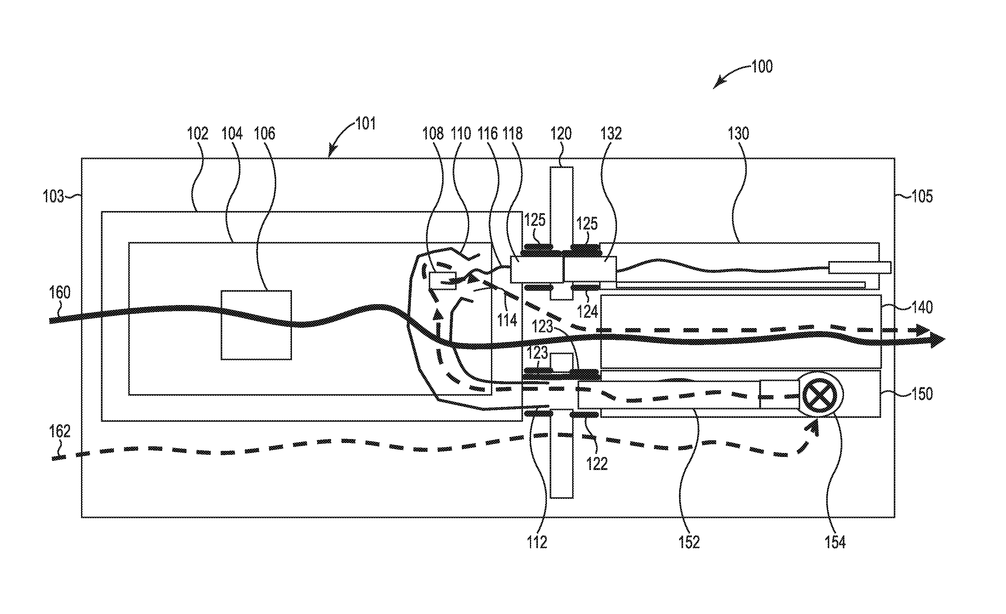
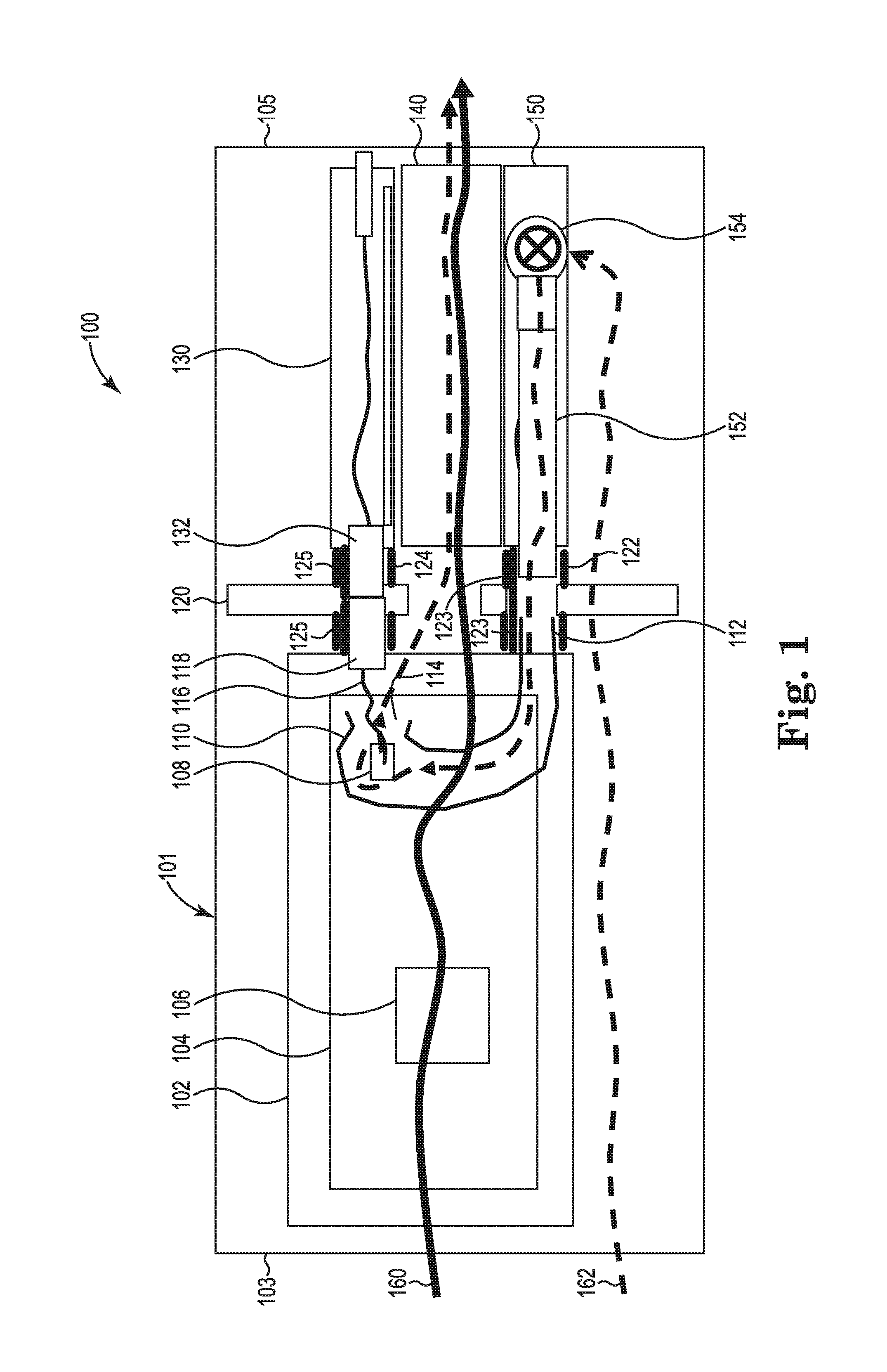
FIG. 1 illustrates a side view of one example of a blade enclosure system 100. Blade enclosure system 100 includes a blade enclosure 101 having a midplane 120, a server blade 102, a network module 130, enclosure fans 140, and a cooling module 150. Midplane 120 includes a first sleeve connector 122 and a second sleeve connector 124. Each sleeve connector 122 and 124 may include shutters 123 and 125, respectively, on each side of each sleeve connector. The shutters are closed when a component is not coupled to a corresponding side of the sleeve connector and open (as shown) when a component is coupled to a corresponding side of the sleeve connector.
Server blade 102 includes a motherboard 104 including a high-power component 106 (e.g., a processor) and a temperature-sensitive component 108 (e.g., an optical transceiver) electrically coupled to the motherboard. Server blade 102 also includes an air duct 110 within which temperature-sensitive component 108 is arranged. In one example, air duct 110 includes a thermally non-conductive material. With server blade 102 installed in the front 103 of blade enclosure 101, one side 112 of air duct 110 is coupled to a first side of sleeve connector 122 to receive cool air and the other side 114 of air duct 110 is open to exhaust hot air. In one example, side 112 of air duct 110 blindmates to sleeve connector 122. Optical transceiver 108 is optically coupled to an optical connector 118 through an optical cable 116. Optical connector 118 is coupled to a first side of sleeve connector 124. In one example, optical connector 118 blindmates to sleeve connector 124.
Network module 130 includes an optical connector 132. With network module 130 installed in the rear 105 of blade enclosure 101, optical connector 132 is coupled to a second side of sleeve connector 124. In one example, optical connector 132 blindmates to sleeve connector 124. Enclosure fans 140 are installed in the rear 105 of blade enclosure 101. Cooling module 150 includes an air manifold 152. In one example, cooling module 150 includes a fan 154 mechanically coupled to air manifold 152 to deliver cool air to the air manifold. With cooling module 150 installed in the rear 105 of blade enclosure 101, air manifold 152 is coupled to a second side of sleeve connector 122. In one example, air manifold 152 blindmates to sleeve connector 122.
In operation, enclosure fans 140 in the rear 105 of blade enclosure 101 provide a primary air flow path 160 which draws cool air into server blade 102 from the front 103 of the enclosure and exhausts hot air to the rear 105 of the enclosure. Primary air flow path 160 cools high-power component 106 as well as other components (not shown) of server blade 102. Cooling module 150 provides a secondary air flow path 162 by drawing cool air into blade enclosure 101 from the front 103 of the enclosure through enclosure side-channels (not shown) and providing the cool air to air duct 110 through air manifold 152 and sleeve connector 122. The secondary air flow path 162 cools temperature-sensitive component 108 within air duct 110. The hot air within air duct 110, after cooling the temperature-sensitive component 108, is exhausted to merge with the primary air flow path 160.
While FIG. 1 illustrates a blade enclosure 101 with one server blade 102, one network module 130, one cooling module 150, and two sleeve connectors 122 and 124, in other examples, blade enclosure 101 may include any suitable number of server blades, network modules, cooling modules, and corresponding sleeve connectors.
FIGS. 2A-2C illustrate different views of one example of sleeve connector 122 and air connectors 174 and 175. FIG. 2A illustrates air connectors 174 and 175 uninstalled from sleeve connector 122, where the shutters 123 on each side of sleeve connector 122 are closed. FIG. 2B illustrates air connectors 174 and 175 installed in sleeve connector 122, where the shutters 123 (not visible) on each side of sleeve connector 122 are open towards the inner cavities of each side of sleeve connector 122. FIG. 2C illustrates a secondary cool air flow path 182 through cross-sectional views of air connectors 174 and 175 and sleeve connector 122.
Sleeve connector 122 is supported by midplane 120 and includes a first side 170 and a second side 172. First side 170 may be coupled to a first air connector 174, and second side 172 may be coupled to a second air connector 175. Each air connector 174 and 175 includes a connector housing 176 for coupling to sleeve connector 122. Each air connector 174 and 175 also includes a gasket 178 to seal the connection between each air connector 174 and 175 and sleeve connector 122 to prevent air from leaking out of sleeve connector 122 when the air connectors are coupled to the sleeve connector. Connector housing 176 of air connector 174 may transition to an air duct interface 180, and connector housing 176 of air connector 175 may transition to a cooling module interface 181. As illustrated in FIG. 2C, the air flow path 182 passes through cooling module interface 181 of air connector 175, through the second side 172 and then the first side 170 of sleeve connector 122, through air connector 174 and then through air duct interface 180.
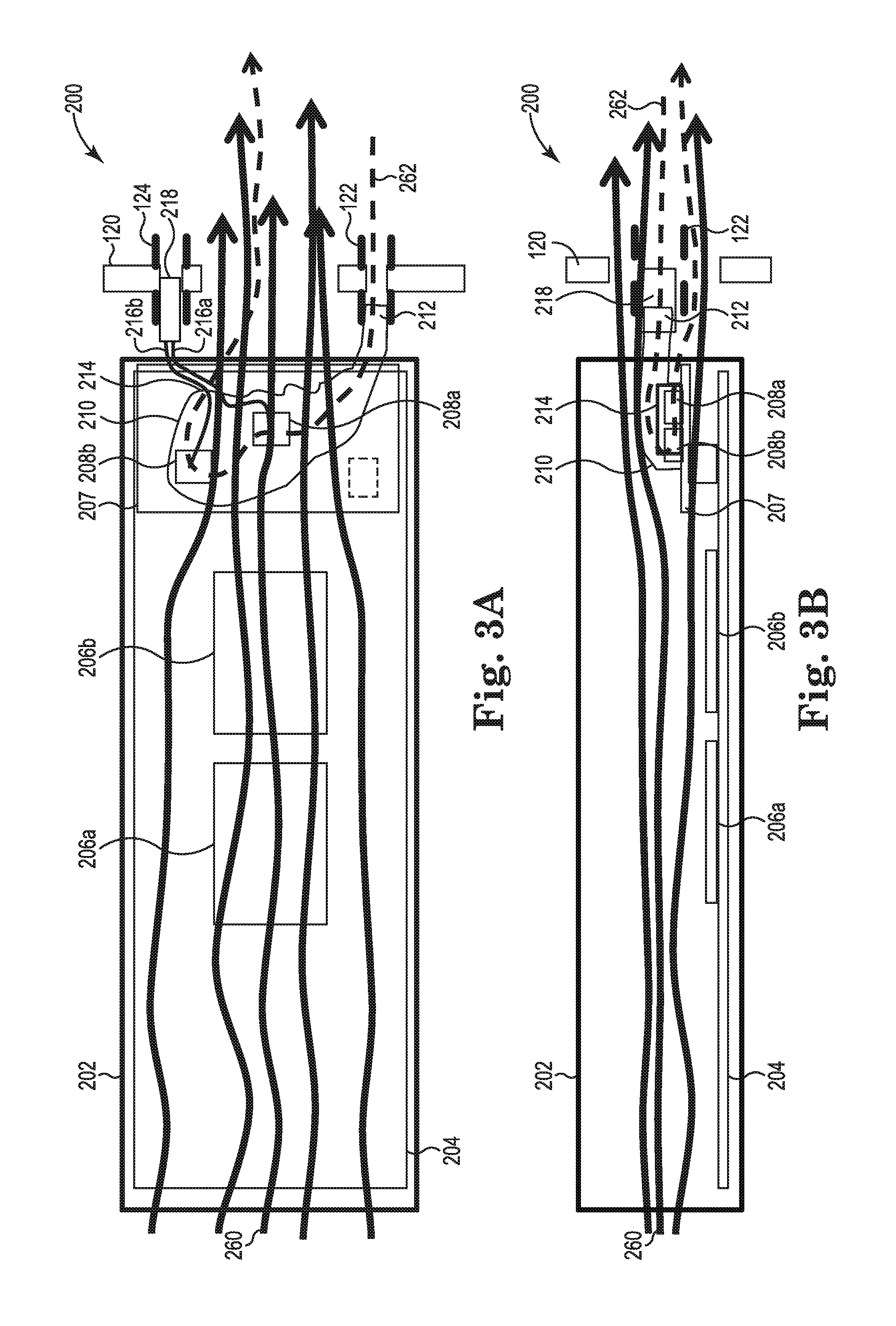
FIGS. 3A and 3B illustrate a side view and a top view, respectively, of one example of a system 200 including secondary reverse cooling. System 200 includes a midplane 120 and a server blade 202. The blade enclosure and other components (e.g., network modules, enclosure fans, and cooling modules) of system 200 have been excluded from FIGS. 3A and 3B for simplicity. Midplane 120 includes first sleeve connector 122 and second sleeve connector 124 as previously described and illustrated with reference to FIG. 1.
Server blade 202 includes a motherboard 204 including high-power components (e.g., processors) 206a and 206b and a mezzanine card 207 including temperature-sensitive components 208a and 208b (e.g., optical transceivers). Mezzanine card 207 also includes an air duct 210 within which temperature-sensitive components 208a and 208b are arranged. With server blade 202 installed in a blade enclosure, one side 212 of air duct 210 is coupled to a first side of sleeve connector 122 to receive cool air and the other side 214 of air duct 210 is open to exhaust secondary hot air. Optical transceivers 208a and 208b are optically coupled to an optical connector 218 through optical cables 216a and 216b, respectively. Optical connector 218 is coupled to a first side of sleeve connector 124.
In operation, enclosure fans (not shown) in the rear of a blade enclosure provide a primary air flow path 260 which draws cool air into the server blade 202 from the front of the blade enclosure and exhausts hot air to the rear of the enclosure. Primary air flow path 260 cools high-power components 206a and 206b as well as other components (not shown) of server blade 202. A cooling module (not shown) provides a secondary air flow path 262 which draws cool air into the blade enclosure and provides the cool air to air duct 210 through sleeve connector 122. The secondary air flow path 262 cools temperature-sensitive components 208a and 208b within air duct 210. The secondary hot air within air duct 210, after cooling the temperature-sensitive components 208a and 208b, is exhausted into the primary air flow path 260.
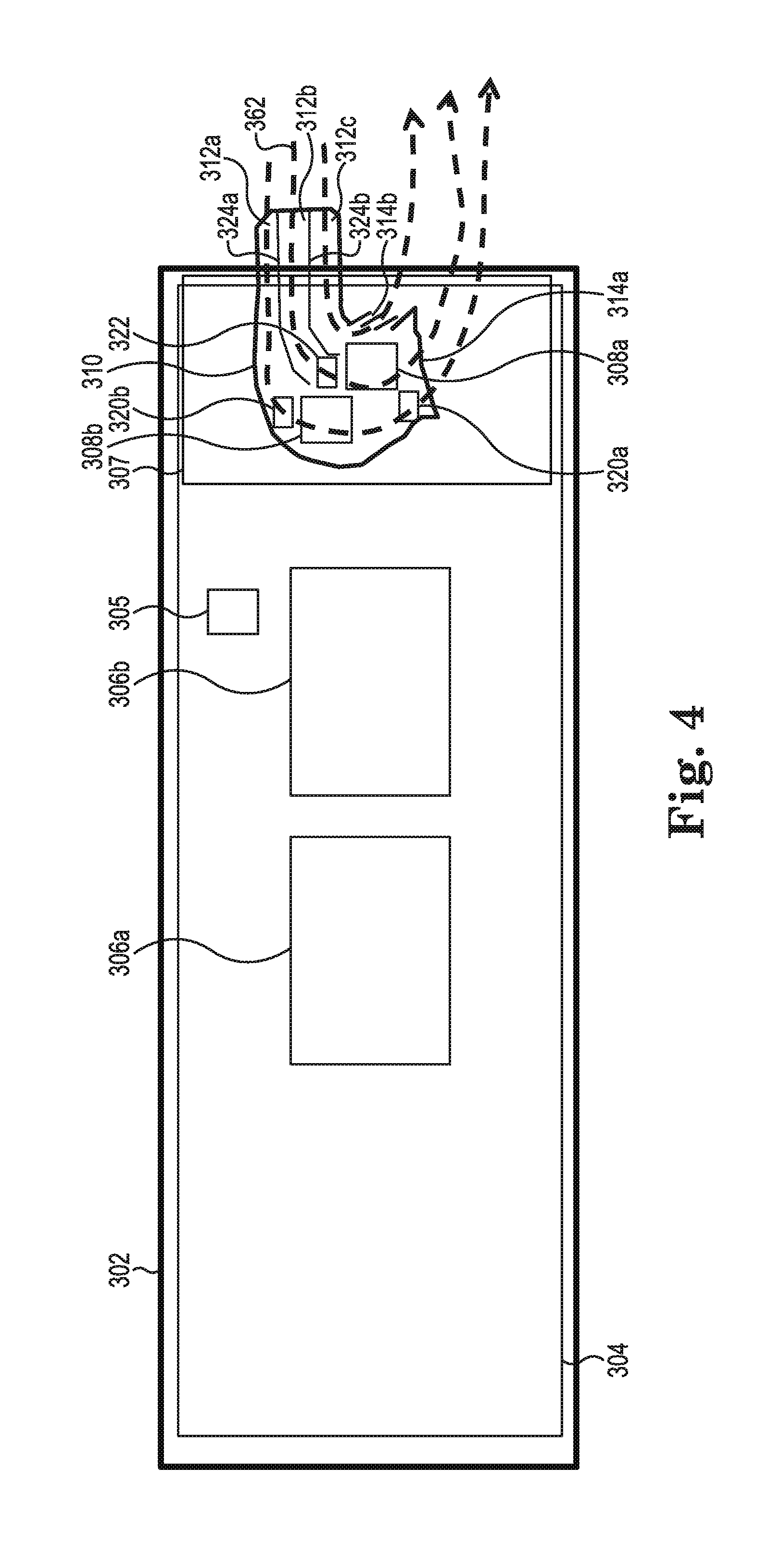
FIG. 4 illustrates a side view of one example of a server blade 302. Server blade 302 includes a motherboard 304 including high-power components 306a and 306b (e.g., processors), a sever management controller 305, and a mezzanine card 307. Mezzanine card 307 includes temperature-sensitive components 308a and 308b (e.g., optical transceivers), temperature sensors 320a and 320b, and an air flow sensor 322. Mezzanine card 307 also includes an air duct 310 within which temperature-sensitive components 308a and 308b, temperature sensors 320a and 320b, and air flow sensor 322 are arranged.
Air duct 310 may include interior dividing walls 324a and 324b to direct a secondary air flow 362 to multiple temperature-sensitive components 308a and 308b within the air duct. In addition, air duct 310 may include multiple air vents 314a and 314b for the secondary hot air to be exhausted. Air flow sensor 322 may measure the incoming secondary air flow delivered from a cooling module. Temperature sensors 320a and 320b may measure how much the secondary cool air is heated. Air flow sensor 322 and temperature sensors 320a and 320b may communicate with server management controller 305, which in turn may communicate with an enclosure manager (not shown). The enclosure manager may communicate with a cooling module controller, thereby enabling the cooling module controller to collect the secondary air flow rate and secondary hot air temperature information. The secondary air flow rate and secondary hot air temperature information may be used by the cooling module controller to adjust the secondary cool air delivered to server blade 302 by a cooling module.
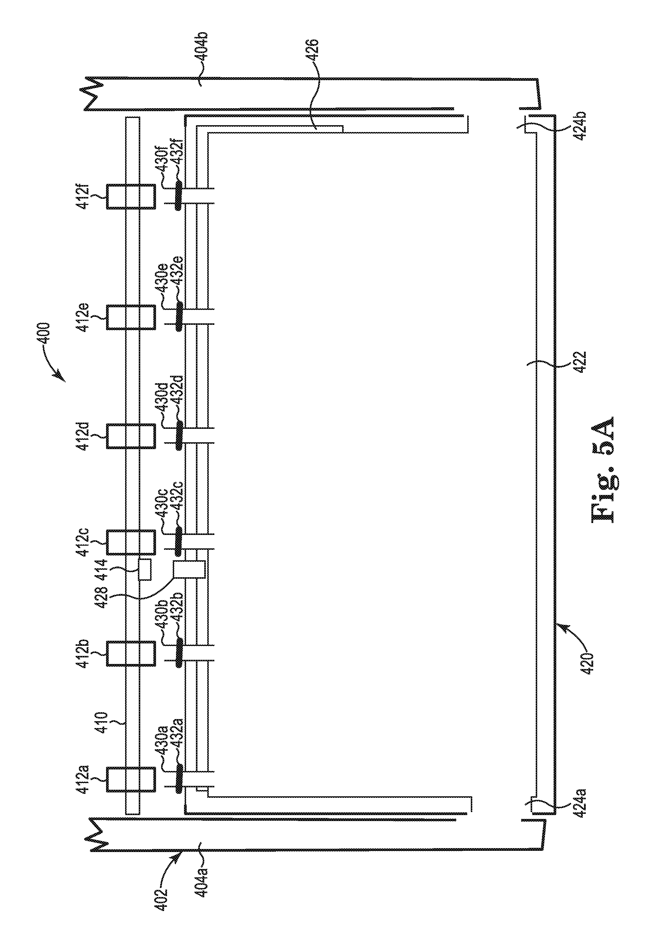
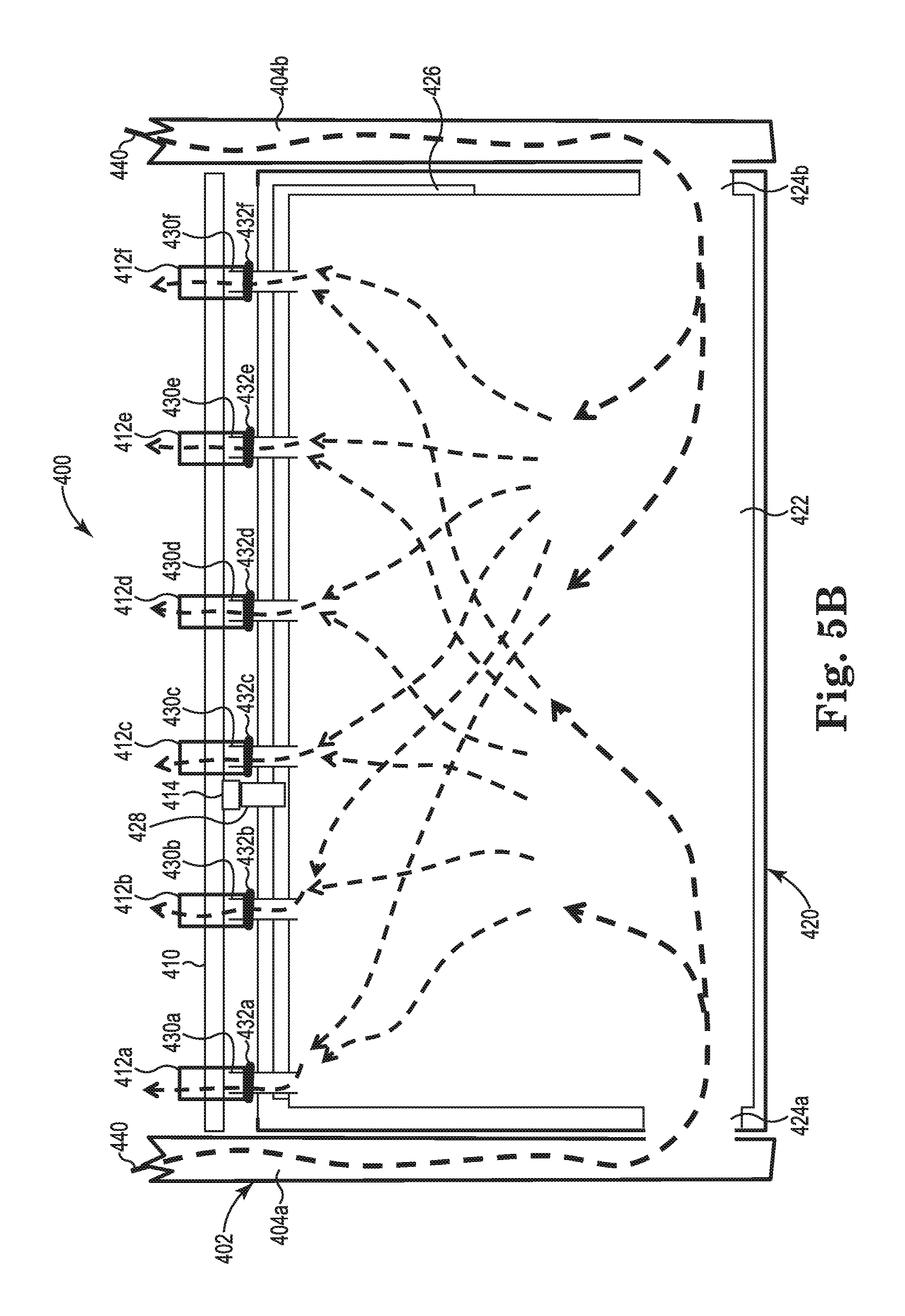
FIG. 5A illustrates a top view of one example of a system 400 with an uninstalled cooling module 420 and FIG. 5B illustrates a top view of one example of system 400 with cooling module 420 installed. System 400 includes a blade enclosure 402 having side channels 404a and 404b and a midplane 410. Midplane 410 supports a plurality of sleeve connectors 412a-412f and a midplane power and management signal connector 414.
Cooling module 420 includes cool air intake ports 424a and 424b, an air manifold 422, a controller board 426, a cooling module power and management signal connector 428 electrically coupled to the controller board, and a plurality of air connectors 430a-430f. Each air connector 430a-430f includes an air connector gasket 432a-432f, respectively, Cool air intake ports 424a and 424b deliver cool air to air manifold 422, which delivers cool air to air connectors 430a-430f.
With cooling module 420 installed in blade enclosure 402 as illustrated in FIG. 5B, each air connector 430a-430f is coupled to one side of each sleeve connector 412a-412f, respectively. In addition, cooling module power and management signal connector 428 is communicatively coupled to midplane power and management signal connector 414. In this example, cooling module 420 is a passive cooling module (i.e., does not include fans) in which negative pressure in server blades (not shown) coupled to the other side of sleeve connectors 412a-412f causes air from air manifold 422 to be drawn out through the corresponding air connectors 412a-412f. In turn, secondary cool air is pulled from enclosure side channels 404a and 404b via cool air intake ports 424a and 424b, respectively, as indicated at 440. Air manifold 422 may include air baffles (not shown) for secondary air 440 to be evenly distributed to air connectors 412a-412f.
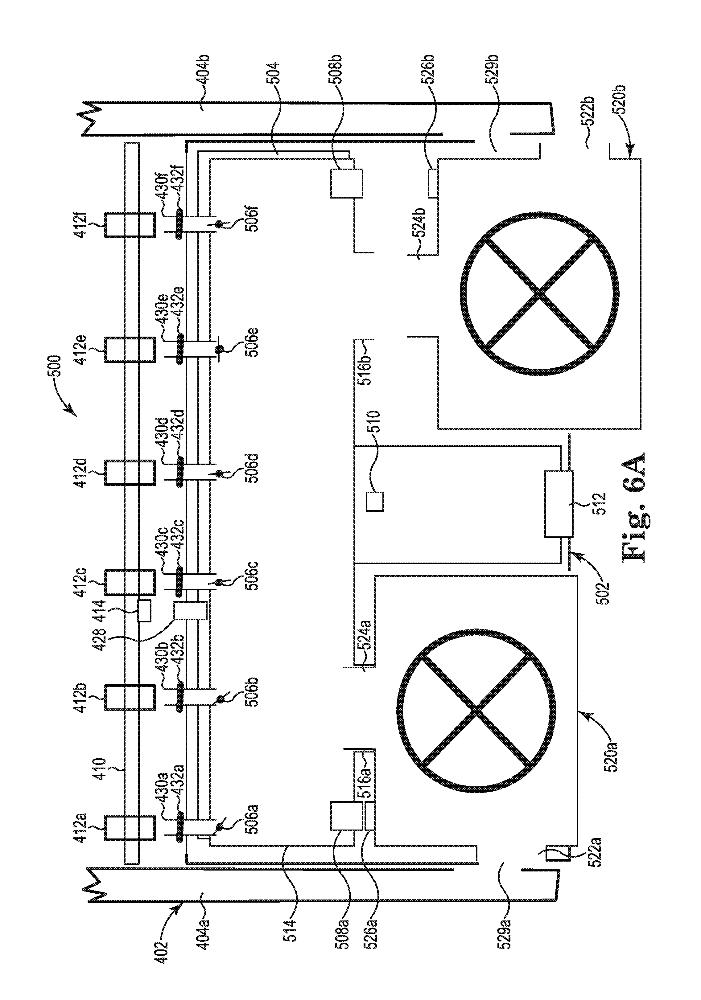
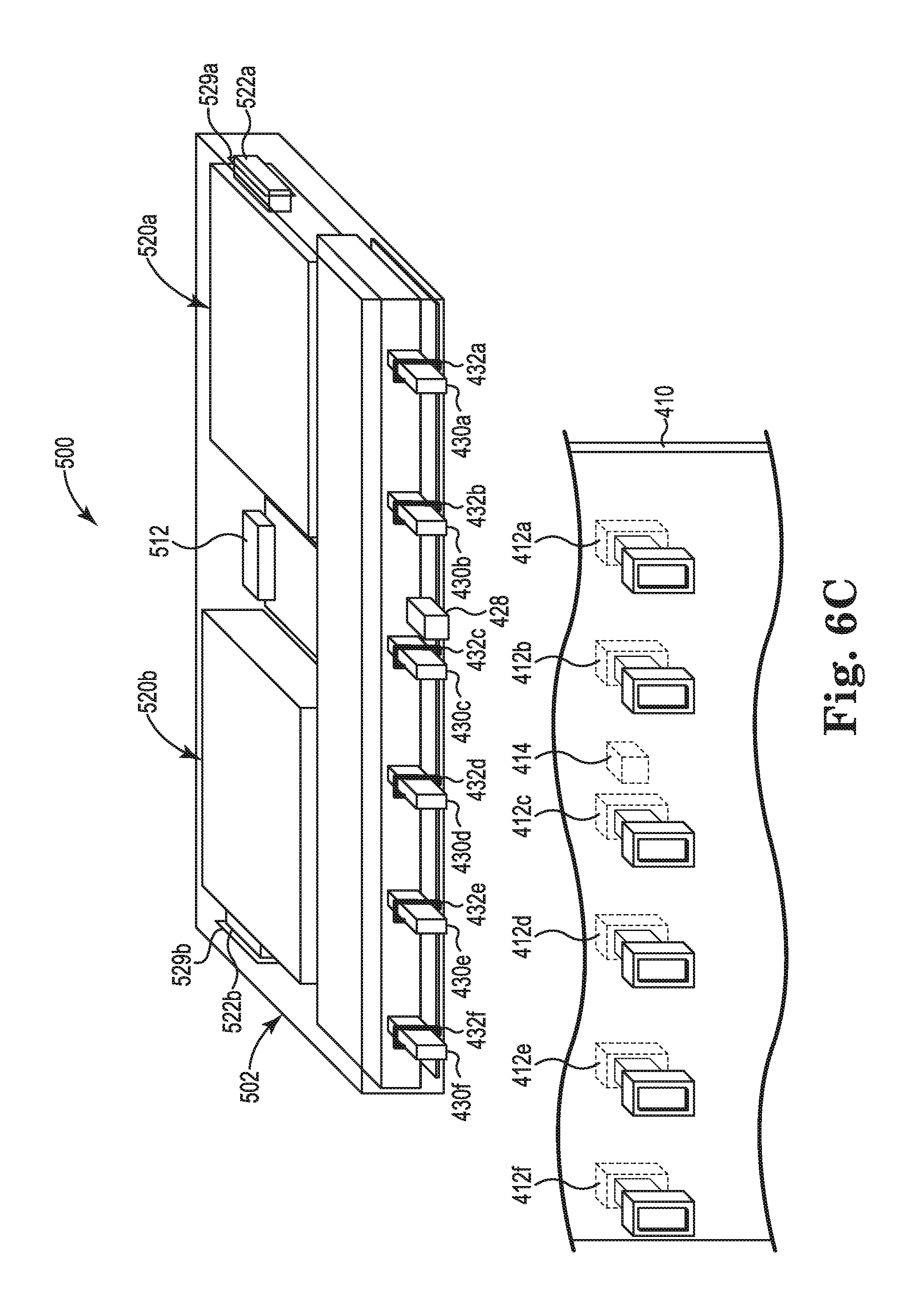
FIGS. 6A-6C illustrate different views of another example of a system 500 including a cooling module 502. FIG. 6A illustrates a top view of system 500 with an uninstalled cooling module 502 in which cooling module 502 includes an uninstalled fan 520b. FIG. 6B illustrates a top view of system 500 with an installed cooling module 502, FIG. 6C illustrates a perspective view of system 500 with an uninstalled cooling module 500.
As illustrated in FIG. 6A, system 500 includes a blade enclosure 402 having side channels 404a and 404b and a midplane 410. Midplane 410 supports a plurality of sleeve connectors 412a-412f and a midplane power and management signal connector 414. Cooling module 502 includes a controller board 504, a cooling module power and management signal connector 428 electrically coupled to the controller board, a first fan power and management signal connector 508a electrically coupled to the controller board, a second fan power and management signal connector 508b electrically coupled to the controller board, a cooling module controller 510 electrically coupled to the controller board, and status displays 512 electrically coupled to the controller board. Cooling module 502 also includes an air manifold 514, a plurality of air flow regulators 506a-506f, and a plurality of air connectors 430a-430f. Each air connector 430a-430f includes an air connector gasket 432a-432f, respectively. Cooling module 502 also includes a first removable fan 520a and a second removable fan 520b, which may provide a pair of redundant fans.
Each fan 520a and 520b includes a cool air intake port 522a and 522b and a cool air delivery port 524a and 524b, respectively. Each fan 520a and 520b also includes a fan power and management signal connector 526a and 526b, respectively. With fans 520a and 520b installed as illustrated in FIG. 6B, fan 520b is rotated 180.degree. with respect to fan 520a such that both fans have their cool air intake ports 522a and 522b aligned with cool air intake ports 529a and 529b, respectively, of cooling module 502. The cool air delivery ports 524a and 524b of fans 520a and 520b are coupled to air manifold 514 via air manifold ports 516a and 516b, respectively. The fan power and management signal connectors 526a and 526b of fans 520a and 520b are communicatively coupled to fan power and management signal connectors 508a and 508b, respectively.
As illustrated in FIG. 6A, air manifold 514 may include air flow regulators 506a-506f for each air connector 430a-430f to individually control the flow of air to each air connector 430a-430f, respectively. Air manifold 514 may include baffles (not shown) to route air within air manifold 514, and air flow regulators 506a-506f may be positioned within corresponding air baffles, to control the air flows directed to the corresponding air connectors 430a-430f. Air flow regulators 506a-506f have been excluded from FIG. 6B for simplicity. Each air flow regulator 506a-506f may be controlled by cooling module controller 510. Cooling module controller 510 may also control fans 520a and 520b via fan power and management signal connectors 508a and 508b and fan power and management signal connectors 526a and 526b, respectively. Cooling module controller 510 may communicate with an enclosure manager (not shown) via cooling module power and management signal connector 428 and midplane power and management signal connector 414 of enclosure midplane 410. Cooling module controller 510 may communicate with server blades via the enclosure manager to collect secondary cool air flow rate and secondary hot air temperature information. The collected information may be used to adjust the secondary cool air delivered to each server blade by changing the speed of fan 520a and/or 520b and/or by adjusting the corresponding air flow regulators 506a-506f. Status displays 512 may display the operating conditions of components within cooling module 502.
With cooling module 502 installed in blade enclosure 402 as illustrated in FIG. 6B, each air connector 430a-430f is coupled to one side of each sleeve connector 412a-412f, respectively. In addition, cooling module power and management signal connector 428 is communicatively coupled to midplane power and management signal connector 414. In this example, cooling module 502 is an active cooling module in which fans 520a and 520b pull secondary cool air as indicated at 530 from enclosure side channels 404a and 404b via cool air intake ports 522a and 522b, respectively. Fans 520a and 520b deliver the secondary cool air to air manifold 514 via cool air delivery ports 524a and 524b, respectively, and out through the air connectors 430a-430f.
FIGS. 7A and 7B illustrate top views of another example of a system 600 including a cooling module 602. FIG. 7A illustrates cooling module 602 with two fans 620a and 620b installed and FIG. 7B illustrates cooling module 602 with one fan 620a installed. System 600 includes a blade enclosure (not shown) having a midplane 410. Midplane 410 supports a plurality of sleeve connectors 412a-412f and a midplane power and management signal connector 414.
Cooling module 602 includes a controller board 604, a cooling module power and management signal connector 428 electrically coupled to the controller board, a first fan power and management signal connector 608a electrically coupled to the controller board, a second fan power and management signal connector 608b electrically coupled to the controller board, and a cooling module controller 610 electrically coupled to the controller board. Cooling module 602 also includes an air manifold 614 and a plurality of air connectors 430a-430f. Each air connector 430a-430f includes an air connector gasket 432a-432f, respectively. Cooling module 602 may also include a first removable fan 620a and a second removable fan 620b, which may provide a pair of redundant fans. Fans 620a and 620b are installed in fan bays 621a and 621b, respectively, of cooling module 602.
Each fan 620a and 620b includes cool air intake ports 622a and 622b and a cool air delivery port 624a and 624b, respectively. Each fan 620a and 620b also includes a fan power and management signal connector 626a and 626b, respectively. With fans 620a and 620b installed, both fans have the same orientation since both fans pull air from both side of cooling module 602. The cool air intake ports 622a and 622b are aligned with cool air intake ports 629a and 629b of cooling module 602. The cool air delivery ports 624a and 624b of fans 620a and 620b are coupled to air manifold 614 via air manifold ports 616a and 616b, respectively. The fan power and management signal connectors 626a and 626b of fans 620a and 620b are communicatively coupled to fan power and management signal connectors 608a and 608b on controller board 604, respectively. When a fan is not installed as illustrated at air manifold port 616b in FIG. 7B, the air manifold port 616b is closed (e.g., by hinged doors) as indicated at 617, and the fan bay 621b is also closed (e.g., by hinged doors) as indicated at 619.
Cooling module controller 610 may control fans 620a and 620b via fan power and management signal connectors 608a and 608b and fan power and management signal connectors 626a and 626b, respectively. Cooling module controller 610 may also communicate with an enclosure manager (not shown) via cooling module power and management signal connector 428 and midplane power and management signal connector 414 of enclosure midplane 410. Cooling module controller 610 may communicate with server blades via the enclosure manager to collect secondary cool air flow rate and secondary hot air temperature information. The collected information may be used to adjust the secondary cool air delivered to each server blade by changing the speed of fan 620a and/or 620b. In other examples, cooling module 602 may also include air flow regulators for each air connector 432a-432f controlled by cooling module controller 610 as previously described and illustrated with reference to FIG. 6A.
With cooling module 602 installed in a blade enclosure, each air connector 430a-430f is coupled to one side of each sleeve connector 412a-412f, respectively. In addition, cooling module power and management signal connector 428 is communicatively coupled to midplane power and management signal connector 414. In this example, cooling module 602 is an active cooling module in which fans 620a and 620b pull secondary cool air as indicated at 630 from enclosure side channels via cool air intake ports 622a and/or 622b, respectively. As illustrated in FIG. 7A, fans 620a and 620b deliver the secondary cool air to air manifold 614 via cool air delivery ports 624a and/or 624b, respectively, and out through the air connectors 430a-430f. As illustrated in FIG. 7B, fan 620a delivers the secondary cool air to air manifold 614 via cool air delivery port 624a and out through the air connectors 430a-430f.
FIGS. 8A and 8B illustrate a rear view and a side view, respectively, of one example of a system 700 including a mezzanine card 720. System 700 includes system board 704 of a server blade (not shown) including mezzanine card 720. System 700 also includes a blade enclosure midplane 710 supporting a sleeve connector 712.
Mezzanine card 720 includes an air duct 724 and a temperature-sensitive component 722 (e.g., an optical transceiver) arranged within air duct 724. In one example, a first portion of air duct 724 is arranged parallel to mezzanine card 720 and a second portion of air duct 724 is arranged through and perpendicular to mezzanine card 720. The second portion of air duct 724 terminates to an air connector 726, which may blindmate to one side of sleeve connector 712. The other side of sleeve connector 712 may be coupled to an air connector 714 of a cooling module (not shown). The primary air flow path is indicated at 730 and the secondary air flow path is indicated at 732. A portion of the secondary air flow path 732 is opposite to the primary air flow path 730. The secondary cool air passes over temperature-sensitive component 722 and the secondary hot air exhausts into the primary air flow path 730.
FIG. 9 illustrates another example of a system 750 including a mezzanine card 720. In this example, in addition to temperature-sensitive component 722, air duct 724, and air connector 726, mezzanine card 720 also includes sensors 752 and 754, a sensor controller 756, and a sensor signal connector 758. Sensors 752 and 754 are arranged within air duct 724 and may include air flow and/or temperature sensors. Sensor 752 is electrically coupled to sensor controller 756 through a signal path 753. Sensor 754 is electrically coupled to sensor controller 756 through a signal path 755. Sensor controller 756 is electrically coupled to sensor signal connector 758 through a signal path 757.
A cooling module 762 includes an air connector 714, a sensor signal connector 764, and a cooling module controller 766. Sensor signal connector 764 is electrically coupled to cooling module controller 766 through a signal path 765. With a server blade including mezzanine card 720 installed in a blade enclosure, sensor signal connector 758 is electrically coupled to sensor signal connector 764 via connector 760 of midplane 710. Cooling module 762 delivers secondary cool air as indicated by secondary air path 732 to temperature-sensitive component 722. Sensors 752 and 754 sense air flow and/or the temperature within air duct 724, and the air flow rate and/or temperature information is passed to cooling module controller 766 by sensor controller 756. Cooling module controller 766 may use the sensor data to adjust the secondary air flow delivered to temperature-sensitive component 722 by cooling module 762.
Although specific examples have been illustrated and described herein, a variety of alternate and/or equivalent implementations may be substituted for the specific examples shown and described without departing from the scope of the present disclosure. This application is intended to cover any adaptations or variations of the specific examples discussed herein. Therefore, it is intended that this disclosure be limited only by the claims and the equivalents thereof.
* * * * *
D00000
D00001
D00002
D00003
D00004
D00005
D00006
D00007
D00008
D00009
D00010
D00011
D00012
D00013
XML
uspto.report is an independent third-party trademark research tool that is not affiliated, endorsed, or sponsored by the United States Patent and Trademark Office (USPTO) or any other governmental organization. The information provided by uspto.report is based on publicly available data at the time of writing and is intended for informational purposes only.
While we strive to provide accurate and up-to-date information, we do not guarantee the accuracy, completeness, reliability, or suitability of the information displayed on this site. The use of this site is at your own risk. Any reliance you place on such information is therefore strictly at your own risk.
All official trademark data, including owner information, should be verified by visiting the official USPTO website at www.uspto.gov. This site is not intended to replace professional legal advice and should not be used as a substitute for consulting with a legal professional who is knowledgeable about trademark law.