Electrical connector having ribbed ground plate
Johnescu , et al.
U.S. patent number 10,720,721 [Application Number 16/120,164] was granted by the patent office on 2020-07-21 for electrical connector having ribbed ground plate. This patent grant is currently assigned to FCI USA LLC. The grantee listed for this patent is FCI USA LLC. Invention is credited to Jonathan E. Buck, Douglas M. Johnescu, Stuart C. Stoner.


View All Diagrams
| United States Patent | 10,720,721 |
| Johnescu , et al. | July 21, 2020 |
Electrical connector having ribbed ground plate
Abstract
An electrical connector includes a dielectric housing, a plurality of electrical signal contacts carried by the dielectric housing, and a ground plate carried by the dielectric housing. The electrical signal contacts are arranged along a first plane, wherein the signal contacts define signal pairs. The signal contacts further define respective mating and mounting ends. The ground plate includes a ground plate body oriented in a second plane that is substantially parallel to the first plane and offset from the first plane. The ground plate body defines first and second opposed surfaces. The ground plate includes at least one rib that defines first and second opposed surfaces, wherein the first surface of the rib projects from the first surface of the ground plate body in a direction toward the first plane between adjacent signal pairs, and the second surface is recessed into the second surface of the ground plate body.
| Inventors: | Johnescu; Douglas M. (York, PA), Buck; Jonathan E. (Hershey, PA), Stoner; Stuart C. (Lewisberry, PA) | ||||||||||
|---|---|---|---|---|---|---|---|---|---|---|---|
| Applicant: |
|
||||||||||
| Assignee: | FCI USA LLC (Etters,
PA) |
||||||||||
| Family ID: | 42738046 | ||||||||||
| Appl. No.: | 16/120,164 | ||||||||||
| Filed: | August 31, 2018 |
Prior Publication Data
| Document Identifier | Publication Date | |
|---|---|---|
| US 20190020137 A1 | Jan 17, 2019 | |
Related U.S. Patent Documents
| Application Number | Filing Date | Patent Number | Issue Date | ||
|---|---|---|---|---|---|
| 15283341 | Oct 1, 2016 | 10096921 | |||
| 14339769 | Jul 24, 2014 | 9461410 | |||
| 13755628 | Jan 31, 2013 | 9048583 | |||
| 12722797 | Mar 12, 2010 | 8366485 | |||
| 61161687 | Mar 19, 2009 | ||||
| Current U.S. Class: | 1/1 |
| Current CPC Class: | H01R 13/6471 (20130101); H01R 13/6587 (20130101); H01R 12/737 (20130101); H01R 13/514 (20130101); H01R 13/6586 (20130101); H01R 43/18 (20130101); H01R 13/648 (20130101); H01R 13/6474 (20130101); H01R 12/724 (20130101); Y10T 29/49204 (20150115); Y10T 29/49208 (20150115) |
| Current International Class: | H01R 13/514 (20060101); H01R 12/73 (20110101); H01R 13/6586 (20110101); H01R 43/18 (20060101); H01R 13/648 (20060101); H01R 13/6471 (20110101); H01R 13/6587 (20110101); H01R 12/72 (20110101); H01R 13/6474 (20110101) |
| Field of Search: | ;439/607.06,6.07,6.09,6.14,108 |
References Cited [Referenced By]
U.S. Patent Documents
| 318186 | May 1885 | Hertzog |
| 741052 | October 1903 | Mahon |
| 1477527 | December 1923 | Raettig |
| D86515 | March 1932 | Cox |
| 2231347 | February 1941 | Reutter |
| 2248675 | July 1941 | Huppert |
| 2430011 | November 1947 | Gillentine |
| 2664552 | December 1953 | Ericsson et al. |
| 2759163 | August 1956 | Ustin et al. |
| 2762022 | September 1956 | Benander et al. |
| 2844644 | July 1958 | Soule, Jr. |
| 2849700 | August 1958 | Perkin |
| 2858372 | October 1958 | Kaufman |
| 3011143 | November 1961 | Dean |
| 3115379 | December 1963 | McKee |
| 3178669 | April 1965 | Roberts |
| 3179738 | April 1965 | De Lyon |
| 3208030 | September 1965 | Evans et al. |
| 3286220 | November 1966 | Marley et al. |
| 3320658 | May 1967 | Bolda et al. |
| 3343120 | September 1967 | Whiting |
| 3366729 | January 1968 | Pauza |
| 3411127 | November 1968 | Adams |
| 3420087 | January 1969 | Hatfield et al. |
| D213697 | April 1969 | Oxley |
| 3482201 | December 1969 | Schneck |
| 3514740 | May 1970 | Filson et al. |
| 3538486 | November 1970 | Shlesinger, Jr. |
| 3560908 | February 1971 | Dell et al. |
| 3591834 | July 1971 | Kolias |
| 3634811 | January 1972 | Teagno et al. |
| 3641475 | February 1972 | Irish et al. |
| 3663925 | May 1972 | Proctor |
| 3669054 | June 1972 | Desso et al. |
| 3692994 | September 1972 | Hirschman et al. |
| 3701076 | October 1972 | Irish |
| 3719981 | March 1973 | Steitz |
| 3732697 | May 1973 | Dickson |
| 3748633 | July 1973 | Lundergan |
| 3827005 | July 1974 | Friend |
| 3845451 | October 1974 | Neidecker |
| 3864004 | February 1975 | Friend |
| 3865462 | February 1975 | Cobaugh et al. |
| 3867008 | February 1975 | Gartland, Jr. |
| 3871015 | March 1975 | Lin et al. |
| 3889364 | June 1975 | Krueger |
| 3942856 | March 1976 | Mindheim et al. |
| 3972580 | August 1976 | Pemberton et al. |
| 4030792 | June 1977 | Fuerst |
| 4056302 | November 1977 | Braun et al. |
| 4070088 | January 1978 | Vaden |
| 4076362 | February 1978 | Ichimura |
| 4082407 | April 1978 | Smorzaniuk et al. |
| 4097266 | June 1978 | Takahashi et al. |
| 4136919 | January 1979 | Howard et al. |
| 4140361 | February 1979 | Sochor |
| 4159861 | July 1979 | Anhalt |
| 4217024 | August 1980 | Aldridge et al. |
| 4232924 | November 1980 | Kline et al. |
| 4260212 | April 1981 | Ritchie et al. |
| 4274700 | June 1981 | Keglewitsch et al. |
| 4288139 | September 1981 | Cobaugh et al. |
| 4371912 | February 1983 | Guzik |
| 4380518 | April 1983 | Wydro, Sr. |
| 4383724 | May 1983 | Verhoeven |
| 4395086 | July 1983 | Marsh |
| 4396140 | August 1983 | Jaffe et al. |
| 4402563 | September 1983 | Sinclair |
| 4403821 | September 1983 | Zimmerman, Jr. et al. |
| 4448467 | May 1984 | Weidler |
| 4462534 | July 1984 | Bitaillou et al. |
| 4464003 | August 1984 | Goodman et al. |
| 4473113 | September 1984 | Whitfield et al. |
| 4473477 | September 1984 | Beall |
| D275849 | October 1984 | Sakurai |
| 4482937 | November 1984 | Berg |
| 4505529 | March 1985 | Barkus |
| 4523296 | June 1985 | Healy, Jr. |
| 4533187 | August 1985 | Kirkman |
| 4536955 | August 1985 | Gudgeon |
| 4545610 | October 1985 | Lakritz et al. |
| 4552425 | November 1985 | Billman |
| 4560222 | December 1985 | Dambach |
| 4564259 | January 1986 | Vandame |
| 4592846 | June 1986 | Metzger et al. |
| 4596428 | June 1986 | Tengler |
| 4596433 | June 1986 | Oesterheld et al. |
| 4624604 | November 1986 | Wagner et al. |
| 4632476 | December 1986 | Schell |
| 4641426 | February 1987 | Hartman et al. |
| 4655515 | April 1987 | Hamsher, Jr. et al. |
| 4664309 | May 1987 | Allen et al. |
| 4664456 | May 1987 | Blair et al. |
| 4664458 | May 1987 | Worth |
| 4678250 | July 1987 | Romine et al. |
| 4685886 | August 1987 | Denlinger et al. |
| 4705205 | November 1987 | Allen et al. |
| 4705332 | November 1987 | Sadigh-Behzadi |
| 4717360 | January 1988 | Czaja |
| 4722470 | February 1988 | Johary |
| 4762500 | August 1988 | Dola et al. |
| 4767344 | August 1988 | Noschese |
| 4776803 | October 1988 | Pretchel et al. |
| 4782893 | November 1988 | Thomas |
| 4790763 | December 1988 | Weber et al. |
| 4806107 | February 1989 | Arnold et al. |
| 4815987 | March 1989 | Kawano et al. |
| 4818237 | April 1989 | Weber |
| 4820169 | April 1989 | Weber et al. |
| 4820182 | April 1989 | Harwath et al. |
| 4824383 | April 1989 | Lemke |
| 4830264 | May 1989 | Bitaillou et al. |
| 4836791 | June 1989 | Grabbe et al. |
| 4844813 | July 1989 | Helfgott et al. |
| 4846727 | July 1989 | Glover et al. |
| 4850887 | July 1989 | Sugawara |
| 4854899 | August 1989 | Matthews |
| 4867713 | September 1989 | Ozu et al. |
| 4871110 | October 1989 | Fukasawa et al. |
| 4878611 | November 1989 | LoVasco et al. |
| 4881905 | November 1989 | Demler, Jr. et al. |
| 4882554 | November 1989 | Akaba et al. |
| 4884335 | December 1989 | McCoy et al. |
| 4898539 | February 1990 | Glover et al. |
| 4900271 | February 1990 | Colleran et al. |
| 4904212 | February 1990 | Durbin et al. |
| 4907990 | March 1990 | Bertho et al. |
| 4908129 | March 1990 | Finsterwalder et al. |
| 4913664 | April 1990 | Dixon et al. |
| 4915641 | April 1990 | Miskin et al. |
| 4917616 | April 1990 | Demler, Jr. et al. |
| 4952172 | August 1990 | Barkus et al. |
| 4963102 | October 1990 | Gettig et al. |
| 4965699 | October 1990 | Jorden et al. |
| 4973257 | November 1990 | Lhotak |
| 4973271 | November 1990 | Ishizuka et al. |
| 4974119 | November 1990 | Martin |
| 4975069 | December 1990 | Fedder et al. |
| 4975084 | December 1990 | Fedder et al. |
| 4979074 | December 1990 | Morley et al. |
| 4997390 | March 1991 | Scholz et al. |
| 5004426 | April 1991 | Barnett |
| 5016968 | May 1991 | Hammond et al. |
| 5024372 | June 1991 | Altman et al. |
| 5024610 | June 1991 | French et al. |
| 5035631 | July 1991 | Piorunneck et al. |
| 5035639 | July 1991 | Kilpatrick et al. |
| 5046960 | September 1991 | Fedder |
| 5052953 | October 1991 | Weber |
| 5055054 | October 1991 | Doutrich |
| 5060844 | October 1991 | Behun et al. |
| 5065282 | November 1991 | Polonio |
| 5066236 | November 1991 | Broeksteeg |
| 5077893 | January 1992 | Mosquera et al. |
| 5082459 | January 1992 | Billman et al. |
| 5083238 | January 1992 | Bousman |
| 5093986 | March 1992 | Mandai et al. |
| 5094623 | March 1992 | Scharf et al. |
| 5094634 | March 1992 | Dixon et al. |
| 5098311 | March 1992 | Roath et al. |
| 5104332 | April 1992 | McCoy |
| 5104341 | April 1992 | Gilissen et al. |
| 5111991 | May 1992 | Clawson et al. |
| 5117331 | May 1992 | Gebara |
| 5118027 | June 1992 | Braun et al. |
| 5120237 | June 1992 | Fussell |
| 5127839 | July 1992 | Korsunsky et al. |
| 5131871 | July 1992 | Banakis et al. |
| 5137959 | August 1992 | Block et al. |
| 5139426 | August 1992 | Barkus et al. |
| 5145104 | September 1992 | Apap et al. |
| 5151056 | September 1992 | McClune |
| 5152700 | October 1992 | Bogursky et al. |
| 5161987 | November 1992 | Sinisi |
| 5163337 | November 1992 | Herron et al. |
| 5163849 | November 1992 | Fogg et al. |
| 5167528 | December 1992 | Nishiyama et al. |
| 5169337 | December 1992 | Ortega et al. |
| 5174770 | December 1992 | Sasaki et al. |
| 5181855 | January 1993 | Mosquera et al. |
| 5194480 | March 1993 | Block et al. |
| 5199885 | April 1993 | Korsunsky et al. |
| 5203075 | April 1993 | Angulas et al. |
| 5207372 | May 1993 | Funari et al. |
| 5213868 | May 1993 | Liberty et al. |
| 5214308 | May 1993 | Nishiguchi et al. |
| 5217381 | June 1993 | Zell et al. |
| 5222649 | June 1993 | Funari et al. |
| 5224867 | July 1993 | Ohtsuki et al. |
| 5228864 | July 1993 | Fusselman et al. |
| 5229016 | July 1993 | Hayes et al. |
| 5238414 | August 1993 | Yaegashi et al. |
| 5254012 | October 1993 | Wang |
| 5255839 | October 1993 | da Costa Alves et al. |
| 5257941 | November 1993 | Lwee et al. |
| 5261155 | November 1993 | Angulas et al. |
| 5269453 | December 1993 | Melton et al. |
| 5274918 | January 1994 | Reed |
| 5275330 | January 1994 | Isaacs et al. |
| 5276964 | January 1994 | Anderson, Jr. et al. |
| 5277624 | January 1994 | Champion et al. |
| 5284287 | February 1994 | Wilson et al. |
| 5285163 | February 1994 | Liotta |
| 5286212 | February 1994 | Broeksteeg |
| 5288949 | February 1994 | Crafts |
| 5295843 | March 1994 | Davis et al. |
| 5298791 | March 1994 | Liberty et al. |
| 5302135 | April 1994 | Lee |
| 5321582 | June 1994 | Casperson |
| 5324569 | June 1994 | Nagesh et al. |
| 5342211 | August 1994 | Broeksteeg |
| 5344327 | September 1994 | Brunker et al. |
| 5346118 | September 1994 | Degani et al. |
| 5354219 | October 1994 | Wanjura |
| 5355283 | October 1994 | Mans et al. |
| 5356300 | October 1994 | Costello et al. |
| 5356301 | October 1994 | Champion et al. |
| 5357050 | October 1994 | Baran et al. |
| 5358417 | October 1994 | Schmedding |
| 5377902 | January 1995 | Hayes |
| 5381314 | January 1995 | Rudy, Jr. et al. |
| 5382168 | January 1995 | Azuma et al. |
| D355409 | February 1995 | Krokaugger |
| 5387111 | February 1995 | DeSantis et al. |
| 5387139 | February 1995 | McKee et al. |
| 5395250 | March 1995 | Englert, Jr. et al. |
| 5400949 | March 1995 | Hirvonen et al. |
| 5403206 | April 1995 | McNamara et al. |
| 5409157 | April 1995 | Nagesh et al. |
| 5410807 | May 1995 | Bross et al. |
| 5427543 | June 1995 | Dynia |
| 5429520 | July 1995 | Morlion et al. |
| 5429521 | July 1995 | Morlion et al. |
| 5431332 | July 1995 | Kirby et al. |
| 5431578 | July 1995 | Wayne |
| 5433617 | July 1995 | Morlion et al. |
| 5433618 | July 1995 | Morlion et al. |
| 5435482 | July 1995 | Variot et al. |
| 5442852 | August 1995 | Danner |
| 5445313 | August 1995 | Boyd et al. |
| 5457342 | October 1995 | Herbst, II |
| 5458426 | October 1995 | Ito |
| 5462456 | October 1995 | Howell |
| 5467913 | November 1995 | Namekawa et al. |
| 5474472 | December 1995 | Niwa et al. |
| 5475922 | December 1995 | Tamura et al. |
| 5477933 | December 1995 | Nguyen |
| 5489750 | February 1996 | Sakemi et al. |
| 5490040 | February 1996 | Gaudenzi et al. |
| 5491303 | February 1996 | Weiss |
| 5492266 | February 1996 | Hoebener et al. |
| 5495668 | March 1996 | Furusawa et al. |
| 5496183 | March 1996 | Soes et al. |
| 5498167 | March 1996 | Seto et al. |
| 5499487 | March 1996 | McGill |
| 5504277 | April 1996 | Danner |
| 5511987 | April 1996 | Shinchi |
| 5512519 | April 1996 | Hwang |
| 5516030 | May 1996 | Denton |
| 5516032 | May 1996 | Sakemi et al. |
| 5518410 | May 1996 | Masami |
| 5519580 | May 1996 | Natarajan et al. |
| 5522727 | June 1996 | Saito et al. |
| 5533915 | July 1996 | Deans |
| 5534127 | July 1996 | Sakai |
| 5539153 | July 1996 | Schwiebert et al. |
| 5542174 | August 1996 | Chiu |
| 5558542 | September 1996 | O'Sullivan et al. |
| 5564952 | October 1996 | Davis |
| 5575688 | November 1996 | Crane, Jr. |
| 5577928 | November 1996 | Duclos |
| 5580283 | December 1996 | O'Sullivan et al. |
| 5586908 | December 1996 | Lorrain |
| 5586914 | December 1996 | Foster, Jr. et al. |
| 5588859 | December 1996 | Maurice |
| 5590463 | January 1997 | Feldman et al. |
| 5591118 | January 1997 | Bierck |
| 5591941 | January 1997 | Acocella et al. |
| 5593322 | January 1997 | Swamy et al. |
| 5605417 | February 1997 | Englert et al. |
| 5609502 | March 1997 | Thumma |
| 5613882 | March 1997 | Hnatuck et al. |
| 5618187 | April 1997 | Goto |
| 5634821 | June 1997 | Crane, Jr. |
| 5637008 | June 1997 | Kozel |
| 5637019 | June 1997 | Crane, Jr. et al. |
| 5643009 | July 1997 | Dinkel et al. |
| 5664968 | September 1997 | Mickievicz |
| 5664973 | September 1997 | Emmert et al. |
| 5667392 | September 1997 | Kocher et al. |
| 5672064 | September 1997 | Provencher et al. |
| 5691041 | November 1997 | Frankeny et al. |
| D387733 | December 1997 | Lee |
| 5697799 | December 1997 | Consoli et al. |
| 5702255 | December 1997 | Murphy et al. |
| 5713746 | February 1998 | Olson et al. |
| 5718606 | February 1998 | Rigby et al. |
| 5727963 | March 1998 | LeMaster |
| 5730609 | March 1998 | Harwath |
| 5733453 | March 1998 | DeBusk |
| 5741144 | April 1998 | Elco et al. |
| 5741161 | April 1998 | Cahaly et al. |
| 5742484 | April 1998 | Gillette et al. |
| 5743009 | April 1998 | Matsui et al. |
| 5743765 | April 1998 | Andrews et al. |
| 5745349 | April 1998 | Lemke |
| 5746608 | May 1998 | Taylor |
| 5749746 | May 1998 | Tan et al. |
| 5755595 | May 1998 | Davis et al. |
| 5766023 | June 1998 | Noschese et al. |
| 5772451 | June 1998 | Dozier, II et al. |
| 5782644 | July 1998 | Kiat |
| 5787971 | August 1998 | Dodson |
| 5795191 | August 1998 | Preputnick et al. |
| 5810607 | September 1998 | Shih et al. |
| 5817973 | October 1998 | Elco |
| 5827094 | October 1998 | Aizawa et al. |
| 5831314 | November 1998 | Wen |
| 5833475 | November 1998 | Mitra |
| 5846024 | December 1998 | Mao et al. |
| 5851121 | December 1998 | Thenaisie et al. |
| 5853797 | December 1998 | Fuchs et al. |
| 5857857 | January 1999 | Fukuda |
| 5860816 | January 1999 | Provencher et al. |
| 5871362 | February 1999 | Campbell et al. |
| 5874776 | February 1999 | Kresge et al. |
| 5876219 | March 1999 | Taylor et al. |
| 5876222 | March 1999 | Gardner et al. |
| 5876248 | March 1999 | Brunker et al. |
| 5882214 | March 1999 | Hillbish et al. |
| 5883782 | March 1999 | Thurston et al. |
| 5887158 | March 1999 | Sample et al. |
| 5888884 | March 1999 | Wojnarowski |
| 5892791 | April 1999 | Moon |
| 5893761 | April 1999 | Longueville |
| 5902136 | May 1999 | Lemke et al. |
| 5904581 | May 1999 | Pope et al. |
| 5908333 | June 1999 | Perino et al. |
| 5913702 | June 1999 | Garcin |
| 5919050 | July 1999 | Kehley et al. |
| 5930114 | July 1999 | Kuzmin et al. |
| 5938479 | August 1999 | Paulson et al. |
| 5943770 | August 1999 | Thenaisie et al. |
| 5955888 | September 1999 | Frederickson et al. |
| 5961355 | October 1999 | Morlion et al. |
| 5967844 | October 1999 | Doutrich et al. |
| 5971817 | October 1999 | Longueville |
| 5975921 | November 1999 | Shuey |
| 5980270 | November 1999 | Fjelstad et al. |
| 5980321 | November 1999 | Cohen et al. |
| 5982249 | November 1999 | Bruns |
| 5984690 | November 1999 | Riechelmann et al. |
| 5984726 | November 1999 | Wu |
| 5992953 | November 1999 | Rabinovitz |
| 5993259 | November 1999 | Stokoe et al. |
| 6012948 | January 2000 | Wu |
| 6022227 | February 2000 | Huang |
| 6024584 | February 2000 | Lemke et al. |
| 6027381 | February 2000 | Lok |
| 6036549 | March 2000 | Wulff |
| 6041498 | March 2000 | Hillbish et al. |
| 6042389 | March 2000 | Lemke et al. |
| 6042394 | March 2000 | Mitra et al. |
| 6042427 | March 2000 | Adriaenssens et al. |
| 6050842 | April 2000 | Ferrill et al. |
| 6050862 | April 2000 | Ishii |
| 6053751 | April 2000 | Humphrey |
| 6059170 | May 2000 | Jimarez et al. |
| 6066048 | May 2000 | Lees |
| 6068520 | May 2000 | Winings et al. |
| 6071152 | June 2000 | Achammer et al. |
| 6077130 | June 2000 | Hughes et al. |
| 6083047 | July 2000 | Paagman |
| 6086386 | July 2000 | Fjelstad et al. |
| 6089878 | July 2000 | Meng |
| 6095827 | August 2000 | Dutkowsky et al. |
| 6113418 | September 2000 | Kjeldahl |
| 6116926 | September 2000 | Ortega et al. |
| 6116965 | September 2000 | Arnett et al. |
| 6123554 | September 2000 | Ortega et al. |
| 6125535 | October 2000 | Chiou et al. |
| 6129592 | October 2000 | Mickievicz et al. |
| 6132255 | October 2000 | Verhoeven |
| 6139336 | October 2000 | Olson |
| 6146157 | November 2000 | Lenoir et al. |
| 6146202 | November 2000 | Ramey et al. |
| 6146203 | November 2000 | Elco et al. |
| 6152747 | November 2000 | McNamara |
| 6152756 | November 2000 | Huang et al. |
| 6154742 | November 2000 | Herriot |
| 6171115 | January 2001 | Mickievicz et al. |
| 6171149 | January 2001 | van Zanten |
| 6174198 | January 2001 | Wu et al. |
| 6179663 | January 2001 | Bradley et al. |
| 6180891 | January 2001 | Murdeshwar |
| 6183287 | February 2001 | Po |
| 6183301 | February 2001 | Paagman |
| 6190213 | February 2001 | Reichart et al. |
| 6193537 | February 2001 | Harper, Jr. et al. |
| 6196871 | March 2001 | Szu |
| 6202916 | March 2001 | Updike et al. |
| 6206722 | March 2001 | Ko et al. |
| 6206735 | March 2001 | Zanolli |
| 6210197 | April 2001 | Yu |
| 6210240 | April 2001 | Comerci et al. |
| 6212755 | April 2001 | Shimada et al. |
| 6215180 | April 2001 | Chen et al. |
| 6219913 | April 2001 | Uchiyama |
| 6220884 | April 2001 | Lin |
| 6220895 | April 2001 | Lin |
| 6220896 | April 2001 | Bertoncini et al. |
| 6227882 | May 2001 | Ortega et al. |
| 6231391 | May 2001 | Ramey et al. |
| 6234851 | May 2001 | Phillips |
| 6238225 | May 2001 | Middlehurst et al. |
| 6241535 | June 2001 | Lemke et al. |
| 6244887 | June 2001 | Commerci et al. |
| 6257478 | July 2001 | Straub |
| 6259039 | July 2001 | Chroneos, Jr. et al. |
| 6261132 | July 2001 | Koseki et al. |
| 6267604 | July 2001 | Mickievicz et al. |
| 6269539 | August 2001 | Takahashi et al. |
| 6274474 | August 2001 | Caletka et al. |
| 6280209 | August 2001 | Bassler et al. |
| 6280230 | August 2001 | Takase et al. |
| 6280809 | August 2001 | Wang et al. |
| 6290552 | September 2001 | Saito et al. |
| 6293827 | September 2001 | Stokoe |
| 6299483 | October 2001 | Cohen et al. |
| 6299484 | October 2001 | Van Woensel |
| 6299492 | October 2001 | Pierini et al. |
| 6302711 | October 2001 | Ito |
| 6309245 | October 2001 | Sweeney |
| 6319075 | November 2001 | Clark et al. |
| 6322377 | November 2001 | Middlehurst et al. |
| 6322379 | November 2001 | Ortega et al. |
| 6322393 | November 2001 | Doutrich et al. |
| 6328602 | December 2001 | Yamasaki et al. |
| 6338635 | January 2002 | Lee |
| 6343955 | February 2002 | Billman et al. |
| 6347952 | February 2002 | Hasegawa et al. |
| 6347962 | February 2002 | Kline |
| 6350134 | February 2002 | Fogg et al. |
| 6354877 | March 2002 | Shuey et al. |
| 6358061 | March 2002 | Regnier |
| 6359783 | March 2002 | Noble |
| 6360940 | March 2002 | Bolde et al. |
| 6361366 | March 2002 | Shuey et al. |
| 6361376 | March 2002 | Onoda |
| 6362961 | March 2002 | Chiou |
| 6363607 | April 2002 | Chen et al. |
| 6364710 | April 2002 | Billman et al. |
| 6371773 | April 2002 | Crofoot et al. |
| 6371813 | April 2002 | Ramey et al. |
| 6375478 | April 2002 | Kikuchi |
| 6375508 | April 2002 | Pickles et al. |
| 6379188 | April 2002 | Cohen et al. |
| 6386914 | May 2002 | Collins et al. |
| 6386924 | May 2002 | Long |
| 6390826 | May 2002 | Affolter et al. |
| 6394818 | May 2002 | Smalley, Jr. |
| 6402566 | June 2002 | Middlehurst et al. |
| 6409543 | June 2002 | Astbury, Jr. et al. |
| 6414248 | July 2002 | Sundstrom |
| 6420778 | July 2002 | Sinyansky |
| 6425785 | July 2002 | Azuma |
| 6428328 | August 2002 | Haba et al. |
| 6431914 | August 2002 | Billman |
| 6431921 | August 2002 | Saito et al. |
| 6435914 | August 2002 | Billman |
| 6450829 | September 2002 | Weisz-Margulescu |
| 6457983 | October 2002 | Bassler et al. |
| 6461183 | October 2002 | Ohkita et al. |
| 6461202 | October 2002 | Kline |
| 6464529 | October 2002 | Jensen et al. |
| 6471523 | October 2002 | Shuey |
| 6471548 | October 2002 | Bertoncini et al. |
| 6472474 | October 2002 | Burkhardt et al. |
| 6482038 | November 2002 | Olson |
| 6485330 | November 2002 | Doutrich |
| 6488549 | December 2002 | Weller et al. |
| 6489567 | December 2002 | Zachrai |
| 6491545 | December 2002 | Spiegel et al. |
| 6494734 | December 2002 | Shuey |
| 6503103 | January 2003 | Cohen et al. |
| 6506076 | January 2003 | Cohen et al. |
| 6506081 | January 2003 | Blanchfield et al. |
| 6517360 | February 2003 | Cohen |
| 6520803 | February 2003 | Dunn |
| 6526519 | February 2003 | Cuthbert |
| 6527587 | March 2003 | Ortega et al. |
| 6527588 | March 2003 | Paagman |
| 6528737 | March 2003 | Kwong et al. |
| 6530134 | March 2003 | Laphan et al. |
| 6537086 | March 2003 | Mac Mullin |
| 6537111 | March 2003 | Brammer et al. |
| 6540522 | April 2003 | Sipe |
| 6540558 | April 2003 | Paagman |
| 6540559 | April 2003 | Kemmick et al. |
| 6544046 | April 2003 | Hahn et al. |
| 6544072 | April 2003 | Olson |
| 6547066 | April 2003 | Koch |
| 6551112 | April 2003 | Li et al. |
| 6551140 | April 2003 | Billman |
| 6554647 | April 2003 | Cohen et al. |
| 6565387 | May 2003 | Cohen |
| 6565388 | May 2003 | Van Woensel et al. |
| 6572409 | June 2003 | Nitta et al. |
| 6572410 | June 2003 | Volstorf et al. |
| 6575774 | June 2003 | Ling et al. |
| 6575776 | June 2003 | Conner et al. |
| 6589071 | July 2003 | Lias et al. |
| 6592381 | July 2003 | Cohen et al. |
| 6602095 | August 2003 | Astbury, Jr. et al. |
| 6604967 | August 2003 | Middlehurst et al. |
| 6607402 | August 2003 | Cohen et al. |
| 6623310 | September 2003 | Billman et al. |
| 6629854 | October 2003 | Murakami |
| 6633490 | October 2003 | Centola et al. |
| 6641410 | November 2003 | Marvin et al. |
| 6641411 | November 2003 | Stoddard et al. |
| 6641825 | November 2003 | Scholz et al. |
| 6652318 | November 2003 | Winings et al. |
| 6663426 | December 2003 | Hasircoglu et al. |
| 6665189 | December 2003 | Lebo |
| 6666693 | December 2003 | Belopolsky et al. |
| 6669514 | December 2003 | Wiebking et al. |
| 6672884 | January 2004 | Toh et al. |
| 6672907 | January 2004 | Azuma |
| 6679709 | January 2004 | Takeuchi |
| 6692272 | February 2004 | Lemke et al. |
| 6695627 | February 2004 | Ortega et al. |
| 6702590 | March 2004 | Zaderej et al. |
| 6702594 | March 2004 | Lee et al. |
| 6705902 | March 2004 | Yi et al. |
| 6709294 | March 2004 | Cohen et al. |
| 6712621 | March 2004 | Li et al. |
| 6712646 | March 2004 | Shindo |
| 6716045 | April 2004 | Meredith |
| 6716068 | April 2004 | Wu |
| 6717825 | April 2004 | Volstorf |
| 6726492 | April 2004 | Yu |
| 6736664 | May 2004 | Ueda et al. |
| 6739910 | May 2004 | Wu |
| 6740820 | May 2004 | Cheng |
| D492295 | June 2004 | Glatt |
| 6743037 | June 2004 | Kassa et al. |
| 6743059 | June 2004 | Korsunsky et al. |
| 6746278 | June 2004 | Nelson et al. |
| 6749439 | June 2004 | Potter et al. |
| 6762067 | July 2004 | Quinones et al. |
| 6764341 | July 2004 | Lappoehn |
| 6769883 | August 2004 | Brid et al. |
| 6769935 | August 2004 | Stokoe et al. |
| 6776635 | August 2004 | Blanchfield et al. |
| 6776649 | August 2004 | Pape et al. |
| 6780027 | August 2004 | Allison |
| 6786771 | September 2004 | Gailus |
| 6790088 | September 2004 | Ono et al. |
| 6796831 | September 2004 | Yasufuku et al. |
| 6797215 | September 2004 | Bonk et al. |
| 6799215 | September 2004 | Giroir et al. |
| D497343 | October 2004 | Busse et al. |
| 6805278 | October 2004 | Olson et al. |
| 6808399 | October 2004 | Rothermel et al. |
| 6808420 | October 2004 | Whiteman, Jr. et al. |
| 6810783 | November 2004 | Larose |
| 6811440 | November 2004 | Rothermel et al. |
| 6814590 | November 2004 | Minich et al. |
| 6814619 | November 2004 | Stokoe et al. |
| 6824391 | November 2004 | Mickievicz et al. |
| 6829143 | December 2004 | Russell et al. |
| 6835072 | December 2004 | Simons et al. |
| 6835103 | December 2004 | Middlehurst et al. |
| 6843686 | January 2005 | Ohnishi et al. |
| 6843687 | January 2005 | McGowan et al. |
| 6848886 | February 2005 | Schmaling et al. |
| 6848944 | February 2005 | Evans |
| 6848950 | February 2005 | Allison et al. |
| 6848953 | February 2005 | Schell et al. |
| 6851974 | February 2005 | Doutrich |
| 6851980 | February 2005 | Nelson et al. |
| 6852567 | February 2005 | Lee et al. |
| D502919 | March 2005 | Studnicky, III |
| 6866549 | March 2005 | Kimura et al. |
| 6869292 | March 2005 | Johnescu et al. |
| 6872085 | March 2005 | Cohen et al. |
| 6884117 | April 2005 | Korsunsky et al. |
| 6890214 | May 2005 | Brown et al. |
| 6890221 | May 2005 | Wagner |
| 6893272 | May 2005 | Yu |
| 6893300 | May 2005 | Zhou et al. |
| 6893686 | May 2005 | Egan |
| 6899566 | May 2005 | Kline et al. |
| 6902411 | June 2005 | Kubo |
| 6905367 | June 2005 | Crane, Jr. et al. |
| 6913490 | July 2005 | Whiteman, Jr. et al. |
| 6918776 | July 2005 | Spink, Jr. |
| 6918789 | July 2005 | Lang et al. |
| 6929504 | August 2005 | Ling et al. |
| 6932649 | August 2005 | Rothermel et al. |
| 6939173 | September 2005 | Elco et al. |
| 6945796 | September 2005 | Bassler et al. |
| 6947012 | September 2005 | Aisenbrey |
| 6951466 | October 2005 | Sandoval et al. |
| 6953351 | October 2005 | Fromm et al. |
| 6969268 | November 2005 | Brunker et al. |
| 6969280 | November 2005 | Chien et al. |
| 6975511 | December 2005 | Lebo et al. |
| 6976886 | December 2005 | Winings et al. |
| 6979202 | December 2005 | Benham et al. |
| 6979215 | December 2005 | Avery et al. |
| 6979226 | December 2005 | Otsu |
| 6981883 | January 2006 | Raistrick et al. |
| 6988902 | January 2006 | Winings et al. |
| 6994569 | February 2006 | Minich et al. |
| 7001189 | February 2006 | McGowan et al. |
| 7021975 | April 2006 | Lappohn |
| 7040901 | May 2006 | Benham et al. |
| 7044794 | May 2006 | Consoli et al. |
| 7059892 | June 2006 | Trout |
| 7059919 | June 2006 | Clark et al. |
| 7065871 | June 2006 | Minich et al. |
| 7070464 | July 2006 | Clark et al. |
| 7074096 | July 2006 | Copper et al. |
| 7086147 | August 2006 | Caletka et al. |
| 7090501 | August 2006 | Scherer et al. |
| 7094102 | August 2006 | Cohen et al. |
| 7097465 | August 2006 | Korsunsky et al. |
| 7097506 | August 2006 | Nakada |
| 7101191 | September 2006 | Benham et al. |
| 7101228 | September 2006 | Hamner et al. |
| 7104812 | September 2006 | Bogiel et al. |
| 7108556 | September 2006 | Cohen et al. |
| 7114963 | October 2006 | Shuey et al. |
| 7114964 | October 2006 | Winings et al. |
| 7118391 | October 2006 | Minich et al. |
| RE39380 | November 2006 | Davis |
| 7131870 | November 2006 | Whiteman, Jr. et al. |
| 7137848 | November 2006 | Trout et al. |
| 7153162 | December 2006 | Mizumura et al. |
| 7160151 | January 2007 | Rigby et al. |
| 7163421 | January 2007 | Cohen et al. |
| 7168963 | January 2007 | Minich et al. |
| 7172461 | February 2007 | Davis et al. |
| 7182642 | February 2007 | Ngo et al. |
| 7182643 | February 2007 | Winings et al. |
| D540258 | April 2007 | Peng et al. |
| 7204699 | April 2007 | Stoner et al. |
| 7207807 | April 2007 | Fogg |
| D541748 | May 2007 | Peng et al. |
| D542736 | May 2007 | Riku |
| 7220141 | May 2007 | Daily et al. |
| 7239526 | July 2007 | Bibee |
| 7241168 | July 2007 | Sakurai et al. |
| 7258562 | August 2007 | Daily et al. |
| D550158 | September 2007 | Victor |
| D550628 | September 2007 | Whiteman, Jr. et al. |
| 7267515 | September 2007 | Lappohn |
| 7270574 | September 2007 | Ngo |
| 7273382 | September 2007 | Igarashi et al. |
| 7278856 | October 2007 | Minich |
| 7281950 | October 2007 | Belopolsky |
| D554591 | November 2007 | Victor |
| 7292055 | November 2007 | Egitto et al. |
| 7303427 | December 2007 | Swain |
| 7309239 | December 2007 | Shuey et al. |
| 7316585 | January 2008 | Smith et al. |
| 7322855 | January 2008 | Mongold et al. |
| 7331802 | February 2008 | Rothermel et al. |
| 7335043 | February 2008 | Ngo et al. |
| 7338321 | March 2008 | Laurx |
| 7347740 | March 2008 | Minich |
| 7351071 | April 2008 | Korsunsky et al. |
| 7381092 | June 2008 | Nakada |
| 7384289 | June 2008 | Minich |
| 7384311 | June 2008 | Sharf et al. |
| 7402064 | July 2008 | Daily et al. |
| 7407387 | August 2008 | Johnescu et al. |
| 7416447 | August 2008 | Chen |
| 7422483 | September 2008 | Avery et al. |
| 7425145 | September 2008 | Ngo |
| 7429176 | September 2008 | Johnescu et al. |
| 7445457 | November 2008 | Frangioso, Jr. et al. |
| 7452242 | November 2008 | Poh et al. |
| 7452249 | November 2008 | Daily et al. |
| 7458839 | December 2008 | Ngo et al. |
| 7467955 | December 2008 | Raistrick et al. |
| 7476108 | January 2009 | Swain et al. |
| 7497735 | March 2009 | Belopolsky |
| 7497736 | March 2009 | Minich et al. |
| 7500871 | March 2009 | Minich et al. |
| 7503804 | March 2009 | Minich |
| 7541135 | June 2009 | Swain |
| 7549897 | June 2009 | Fedder et al. |
| 7553182 | June 2009 | Buck et al. |
| 7588463 | September 2009 | Yamada et al. |
| 7621781 | November 2009 | Rothermel et al. |
| D607822 | January 2010 | Dennes |
| D611908 | March 2010 | Takada et al. |
| 7708569 | May 2010 | Sercu et al. |
| D618180 | June 2010 | Gross et al. |
| D618181 | June 2010 | Gross et al. |
| 7753731 | July 2010 | Cohen et al. |
| 7762843 | July 2010 | Minich et al. |
| D626075 | October 2010 | Truskett et al. |
| 7833065 | November 2010 | Lin et al. |
| D628963 | December 2010 | Sau et al. |
| 7883366 | February 2011 | Davis et al. |
| 7976326 | July 2011 | Stoner |
| 7988456 | August 2011 | Davis et al. |
| 8011957 | September 2011 | Pan |
| D651177 | December 2011 | Luo |
| 8079847 | December 2011 | Davis et al. |
| D653621 | February 2012 | Gross et al. |
| 8109770 | February 2012 | Perugini et al. |
| 8119926 | February 2012 | Murphy |
| 8157599 | April 2012 | Wei |
| 8231415 | July 2012 | Johnescu et al. |
| 8277241 | October 2012 | Horchler et al. |
| 8366485 | February 2013 | Johnescu et al. |
| 8408939 | April 2013 | Davis et al. |
| 8414199 | April 2013 | Ishigami |
| 8465213 | June 2013 | Tamura et al. |
| 8480413 | July 2013 | Minich et al. |
| RE44556 | October 2013 | Minich et al. |
| 8616919 | December 2013 | Stoner |
| D712843 | September 2014 | Buck et al. |
| D718253 | November 2014 | Zerebilov et al. |
| D720698 | January 2015 | Zerebilov et al. |
| D727268 | April 2015 | Buck et al. |
| D727852 | April 2015 | Buck et al. |
| 9048583 | June 2015 | Johnescu et al. |
| D745852 | December 2015 | Harper, Jr. et al. |
| D751507 | March 2016 | Horchler |
| 9461410 | October 2016 | Johnescu et al. |
| 10096921 | October 2018 | Johnescu et al. |
| 2001/0003685 | June 2001 | Aritani |
| 2001/0008189 | July 2001 | Reede |
| 2001/0012729 | August 2001 | Van Woensel |
| 2001/0041477 | November 2001 | Billman et al. |
| 2001/0046810 | November 2001 | Cohen |
| 2001/0046816 | November 2001 | Saito et al. |
| 2002/0013101 | January 2002 | Long |
| 2002/0039857 | April 2002 | Naito et al. |
| 2002/0084105 | July 2002 | Geng et al. |
| 2002/0098727 | July 2002 | McNamara et al. |
| 2002/0106930 | August 2002 | Pape et al. |
| 2002/0106932 | August 2002 | Holland et al. |
| 2002/0111068 | August 2002 | Cohen et al. |
| 2002/0127903 | September 2002 | Billman et al. |
| 2002/0142629 | October 2002 | Zaderej et al. |
| 2002/0142676 | October 2002 | Hosaka et al. |
| 2002/0159235 | October 2002 | Miller et al. |
| 2002/0173177 | November 2002 | Korsunsky et al. |
| 2002/0187688 | December 2002 | Marvin et al. |
| 2002/0193019 | December 2002 | Blanchfield et al. |
| 2003/0116857 | June 2003 | Taniguchi et al. |
| 2003/0119378 | June 2003 | Avery |
| 2003/0143894 | July 2003 | Kline et al. |
| 2003/0171010 | September 2003 | Winings et al. |
| 2003/0203665 | October 2003 | Ohnishi et al. |
| 2003/0219999 | November 2003 | Minich et al. |
| 2003/0220021 | November 2003 | Whiteman et al. |
| 2003/0236035 | December 2003 | Kuroda et al. |
| 2004/0018757 | January 2004 | Lang et al. |
| 2004/0038590 | February 2004 | Lang et al. |
| 2004/0072470 | April 2004 | Lang et al. |
| 2004/0077224 | April 2004 | Marchese |
| 2004/0087196 | May 2004 | Lang et al. |
| 2004/0114866 | June 2004 | Hiramatsu |
| 2004/0157477 | August 2004 | Johnson et al. |
| 2004/0224559 | November 2004 | Nelson et al. |
| 2004/0235321 | November 2004 | Mizumura et al. |
| 2004/0259420 | December 2004 | Wu |
| 2005/0009402 | January 2005 | Chien et al. |
| 2005/0026503 | February 2005 | Trout et al. |
| 2005/0032401 | February 2005 | Kobayashi |
| 2005/0048838 | March 2005 | Korsunsky et al. |
| 2005/0079763 | April 2005 | Lemke et al. |
| 2005/0101166 | May 2005 | Kameyama |
| 2005/0101188 | May 2005 | Benham et al. |
| 2005/0112952 | May 2005 | Wang et al. |
| 2005/0118869 | June 2005 | Evans |
| 2005/0170700 | August 2005 | Shuey et al. |
| 2005/0196987 | September 2005 | Shuey et al. |
| 2005/0202722 | September 2005 | Regnier et al. |
| 2005/0215121 | September 2005 | Tokunaga |
| 2005/0227552 | October 2005 | Yamashita et al. |
| 2005/0277315 | December 2005 | Mongold et al. |
| 2005/0287869 | December 2005 | Kenny et al. |
| 2006/0003620 | January 2006 | Daily et al. |
| 2006/0014433 | January 2006 | Consoli et al. |
| 2006/0024983 | February 2006 | Cohen et al. |
| 2006/0024984 | February 2006 | Cohen et al. |
| 2006/0046526 | March 2006 | Minich |
| 2006/0051987 | March 2006 | Goodman et al. |
| 2006/0068610 | March 2006 | Belopolsky |
| 2006/0068641 | March 2006 | Hull et al. |
| 2006/0073709 | April 2006 | Reid |
| 2006/0116857 | June 2006 | Sevic et al. |
| 2006/0121749 | June 2006 | Fogg |
| 2006/0128197 | June 2006 | McGowan et al. |
| 2006/0141818 | June 2006 | Ngo |
| 2006/0183377 | August 2006 | Sinsheimer |
| 2006/0192274 | August 2006 | Lee et al. |
| 2006/0216969 | September 2006 | Bright et al. |
| 2006/0228912 | October 2006 | Morlion et al. |
| 2006/0232301 | October 2006 | Morlion et al. |
| 2006/0281354 | December 2006 | Ngo et al. |
| 2007/0004287 | January 2007 | Marshall |
| 2007/0021002 | January 2007 | Laurx et al. |
| 2007/0042639 | February 2007 | Manter et al. |
| 2007/0071391 | March 2007 | Mazotti et al. |
| 2007/0099455 | May 2007 | Rothermel et al. |
| 2007/0099512 | May 2007 | Sato |
| 2007/0155241 | July 2007 | Lappohn |
| 2007/0183707 | August 2007 | Umezawa |
| 2007/0183724 | August 2007 | Sato |
| 2007/0202715 | August 2007 | Daily et al. |
| 2007/0202747 | August 2007 | Sharf et al. |
| 2007/0205774 | September 2007 | Minich |
| 2007/0207641 | September 2007 | Minich |
| 2007/0293084 | December 2007 | Ngo |
| 2008/0032524 | February 2008 | Lemke et al. |
| 2008/0045079 | February 2008 | Minich et al. |
| 2008/0176453 | July 2008 | Minich et al. |
| 2008/0232737 | September 2008 | Ishigami et al. |
| 2008/0246555 | October 2008 | Kirk et al. |
| 2008/0248670 | October 2008 | Daily et al. |
| 2008/0316729 | December 2008 | Rothermel et al. |
| 2009/0011643 | January 2009 | Amleshi et al. |
| 2010/0055983 | March 2010 | Wu |
| 2010/0093209 | April 2010 | Liu et al. |
| 2010/0216342 | August 2010 | Lin |
| 2010/0240233 | September 2010 | Johnescu et al. |
| 2010/0291803 | November 2010 | Kirk |
| 2011/0097934 | April 2011 | Minich |
| 2011/0159744 | June 2011 | Buck |
| 2011/0195593 | August 2011 | McGrath et al. |
| 2012/0202363 | August 2012 | McNamara et al. |
| 2012/0214343 | August 2012 | Buck et al. |
| 2012/0289095 | November 2012 | Kirk |
| 2013/0005160 | January 2013 | Minich |
| 2013/0090025 | April 2013 | Trout et al. |
| 2013/0122744 | May 2013 | Morgan et al. |
| 2013/0149881 | June 2013 | Johnescu et al. |
| 2013/0149890 | June 2013 | Schroll et al. |
| 2013/0195408 | August 2013 | Hermeline et al. |
| 2013/0210246 | August 2013 | Davis et al. |
| 2013/0273756 | October 2013 | Stoner et al. |
| 2013/0273781 | October 2013 | Buck et al. |
| 2014/0017957 | January 2014 | Horchler et al. |
| 2014/0227911 | August 2014 | Lim et al. |
| 2014/0335707 | November 2014 | Johnescu et al. |
| 2017/0025774 | January 2017 | Johnescu et al. |
| 1665181 | Apr 1974 | DE | |||
| 3529218 | Feb 1986 | DE | |||
| 3605316 | Aug 1987 | DE | |||
| 4040551 | Jun 1991 | DE | |||
| 10226279 | Nov 2003 | DE | |||
| 102010005001 | Aug 2010 | DE | |||
| 0 212 764 | Mar 1987 | EP | |||
| 0273683 | Jul 1988 | EP | |||
| 0321257 | Jun 1989 | EP | |||
| 0337634 | Oct 1989 | EP | |||
| 0442785 | Aug 1991 | EP | |||
| 0486298 | May 1992 | EP | |||
| 0486298 | May 1992 | EP | |||
| 0560550 | Sep 1993 | EP | |||
| 0562691 | Sep 1993 | EP | |||
| 0591772 | Apr 1994 | EP | |||
| 0623248 | Nov 1994 | EP | |||
| 0635910 | Jan 1995 | EP | |||
| 0706240 | Apr 1996 | EP | |||
| 0782220 | Jul 1997 | EP | |||
| 0789422 | Aug 1997 | EP | |||
| 0843383 | May 1998 | EP | |||
| 0891016 | Jan 1999 | EP | |||
| 1024556 | Aug 2000 | EP | |||
| 1091449 | Apr 2001 | EP | |||
| 1111730 | Jun 2001 | EP | |||
| 1148587 | Oct 2001 | EP | |||
| 1162705 | Aug 1969 | GB | |||
| 57058115 | Apr 1982 | JP | |||
| S60-72663 | Apr 1985 | JP | |||
| 02/278893 | Nov 1990 | JP | |||
| 05-21119 | Jan 1993 | JP | |||
| 0668943 | Mar 1994 | JP | |||
| 06236788 | Aug 1994 | JP | |||
| 07114958 | May 1995 | JP | |||
| 07169523 | Jul 1995 | JP | |||
| H08-96918 | Apr 1996 | JP | |||
| 08125379 | May 1996 | JP | |||
| 09199215 | Jul 1997 | JP | |||
| 11185886 | Jul 1999 | JP | |||
| 2000003743 | Jan 2000 | JP | |||
| 2000003744 | Jan 2000 | JP | |||
| 2000003745 | Jan 2000 | JP | |||
| 2000003746 | Jan 2000 | JP | |||
| 2000228243 | Aug 2000 | JP | |||
| 2001135388 | May 2001 | JP | |||
| 2001305182 | Oct 2001 | JP | |||
| 2002008790 | Jan 2002 | JP | |||
| 2003217785 | Jul 2003 | JP | |||
| 2007-128706 | May 2007 | JP | |||
| 05344728 | Nov 2013 | JP | |||
| 100517561 | Sep 2005 | KR | |||
| 46872 | Aug 2003 | TW | |||
| 576555 | Feb 2004 | TW | |||
| WO 9016093 | Dec 1990 | WO | |||
| WO 96/38889 | Dec 1996 | WO | |||
| WO 9642123 | Dec 1996 | WO | |||
| WO 9720454 | Jun 1997 | WO | |||
| WO 9743885 | Nov 1997 | WO | |||
| WO 9744859 | Nov 1997 | WO | |||
| WO 9745896 | Dec 1997 | WO | |||
| WO 9815989 | Apr 1998 | WO | |||
| WO 0016445 | Mar 2000 | WO | |||
| WO 0129931 | Apr 2001 | WO | |||
| WO 0139332 | May 2001 | WO | |||
| WO 02/058191 | Jul 2002 | WO | |||
| WO 02101882 | Dec 2002 | WO | |||
| WO 02103847 | Dec 2002 | WO | |||
| WO 2005065254 | Jul 2005 | WO | |||
| WO 2006031296 | Mar 2006 | WO | |||
| WO 2006105535 | Oct 2006 | WO | |||
| WO 2007064632 | Jun 2007 | WO | |||
| WO 2008082548 | Jul 2008 | WO | |||
| WO 2008117180 | Oct 2008 | WO | |||
| WO 2008156851 | Dec 2008 | WO | |||
| WO 2011059872 | May 2011 | WO | |||
| WO 2012047619 | Apr 2012 | WO | |||
| WO 2012174120 | Dec 2012 | WO | |||
Other References
|
European Patent Application No. 10753953.8: Extended European Search Report dated Nov. 7, 2013, 6 pages. cited by applicant . European Patent Application No. 12305119.5: Extended European Search Report dated Jul. 11, 2012, 5 pages. cited by applicant . International Application No. PCT/US2003/014370, International Search Report dated Aug. 6, 2003. cited by applicant . International Application No. PCT/US2010/040899, International Search Report and Written Opinion dated Jan. 25, 2011. cited by applicant . International Patent Application No. PCT/US2013/035775: International Search Report and Written Opinion dated Jul. 18, 2013. cited by applicant . International Patent Application No. PCT/US2013/035915: International Search Report and Written Opinion dated Jul. 25, 2013. cited by applicant . International Patent Application No. PCT/US2013/049995: International Search Report dated Oct. 28, 2013. cited by applicant . International Patent Application No. PCT/US2010/027399: International Search Report and Written Opinion dated Nov. 1, 2010. cited by applicant . "1.0 HDMI Right Angle Header Assembly (19 Pin) Lead Free", Molex Incorporated, Jul. 20, 2004, 7 pages. cited by applicant . "1.90 by 1.35mm (.075 by.053) Pitch Impact, Backplane Connector System 3 and 4 Pair, Features and Specification", Molex, www.molex.com/link/Impact.html, 2008, 5 pages. cited by applicant . "4.0 UHD Connector Differential Signal Crosstalk, Reflections", 1998, p. 8-9. cited by applicant . "AMP Z-Dok and Z-Dok and Connectors", Tyco Electronics/AMP, Application Specification #114-13068, Aug. 30, 2005, 17 pages. cited by applicant . "AMP Z-Pack 2mm HM Connector, 2mm Centerline, Eight-Row, Right-Angle Applications", Electrical Performance Report, EPR 889065, Issued Sep. 1998, 59 pages. cited by applicant . "AMP Z-Pack 2mm HM Interconnection System", 1992/994, AMP Incorporated, 6 pages. cited by applicant . "AMP Z-Pack HM-Zd Performance at Gigabit Speeds", Tyco Electronics, Report #20GC014, Rev.B., May 4, 2001, 32 pages. cited by applicant . "B.? Bandwidth and Rise Time Budgets, Module 1-8 Fiber Optic Telecommunications (E-XVI-2a)", http:--cord.org-step.sub.--online-st1-8-st18exvi2a.htm, 2006, 1-3. cited by applicant . "Backplane Connectors", http://www.amphenol-tcs.com/products/connectors/backplane/index.html, Amphenol TCS (ATCS), Jun. 19, 2008, 1-3. cited by applicant . "Champ Z-Dok Connector System", Tyco Electronics, Jan. 2002, 3 pages. cited by applicant . "Daughtercard Hole Pattern: Signal Modules (10 & 25 positions) Connector Assembly", Customer No. C-163-5101-500, Teradyne Connection Systems, Inc., 2001, 1 page. cited by applicant . "FCI's Airmax VS Connector System Honored at DesignCon 2005", http:--www.heilind.com-products-fci-airmax-vs-design.asp, Heilind Electronics, Inc., 2005, 1 page. cited by applicant . "Framatome Connector Specification", May 10, 1999, 1 page. cited by applicant . "GbXI-Trac Backplane Connector System", www.molex.com/cgi-bin, Molex, 2007, 1-3. cited by applicant . "Gig-Array Connector System, Board to Board Connectors", 2005, 4 pages. cited by applicant . "Gig-Array High Speed Mezzanine Connectors 15-40 mm Board to Board", FCI Corporation, Jun. 5, 2006, 1 page. cited by applicant . "HDM Separable Interface Detail", Molex, Feb. 17, 1993, 3 pages. cited by applicant . "HDM Stacker Signal Integrity", http://www.teradyne.com/prods/tcs/products/connectors/mezzanine/hdm.sub.-- - - stacker/sidnintegrity.html, Amphenol TCS (ATCS), Feb. 2, 2006, 3 pages. cited by applicant . "HDM, HDM Plus Connectors", http:--www.teradyne.com-prods-tcs-products-connectors-backplane-hdm-index- - .html, Amphenol TCS, 2006, 1 page. cited by applicant . "HDM/HDM Plus, 2mm, Backplane Interconnection System", Teradyne Connection Systems, 1993, 22 pages. cited by applicant . "High Definition Multimedia Interface (HDMI)", www.molex.com, Molex, Jun. 19, 2008, 2 pages. cited by applicant . "High Speed Backplane Interconnect Solutions", Tyco Electronics, 2007, 6 pages. cited by applicant . "High Speed Characterization Report, SEAM-30-02.0-S-10-2", www.samtec.com, SAMTEC, 2005, 55 pages. cited by applicant . "Honda High-Speed Backplane Connector NSP Series", Honda Connectors, Feb. 7, 2003, 25 pages. cited by applicant . "Impact 3 Pair 10 Column Signal Module", Tyco Electronics, Mar. 25, 2008, 1 page. cited by applicant . "Impact Connector Offered by Tyco Electronic, High Speed Backplane Connector System", Tyco Electronics, Apr. 15, 2008, 12 pages. cited by applicant . "Impact, 3 Pair Header Unguided Open Assembly", Tyco Electronics, Apr. 11, 2008, 1 page. cited by applicant . "Lucent Technologies' Bell Labs and FCI Demonstrate 25gb-S Data Transmission Over Electrical Backplane Connectors", http:--www.lucent.com-press-0205-050201.bla.html, Lucent Tech Bell Labs, Feb. 1, 2005,1-4. cited by applicant . "Metral 1000 Series, 5 Row Receptacle, Right Angle, Press Fit, PCB Mounted Receptacle Assembly", FCI 2001, 1 page. cited by applicant . "Metral 2mm High-Speed Connectors, 1000, 2000, 3000 Series, Electrical Performance Data for Differential Applications", FCI Framatome Group, 2 pages. cited by applicant . "Metral Speed & Density Extensions", FCI, Jun. 3, 1999, 1-25. cited by applicant . "Mezzanine High Speed High-Density Connectors Gig-Array and Meg-Array Electrical Performance Data", FCI Corporation, 10 pages. cited by applicant . "Micro Electronic Interconnects", Alphametals, 1990, 4 pages. cited by applicant . "Millipacs Connector, Type A Specification", Dec. 14, 2004,1 page. cited by applicant . "NSP Series, Backplane High-Speed Data Transmission Cable Connectors", http:--www.honda-connectors.co.jp,Honda Connectors, 2006, 6 pages, English Translation attached. cited by applicant . "Open Pin Field Array Seaf Series", www.samtec.com, SAMTEC, 2005, 1 page. cited by applicant . "Overview for High Density Backplane Connector (Z-Pack TinMan)", Tyco Electronics, 2008, 1 page. cited by applicant . "Overview for High Density Backplane Connectors (Impact) Offered by Tyco Elecctronics", www.tycoelectronics.com/catalog, Tyco Electronics, 2007, 1-2. cited by applicant . "Overview: Backplane Products", http:--www.molex.com-cgi-bin-by-molex-super.sub.--family-super.sub.--fami- - ly.jsp?BV.sub.--SessionID=@, Molex, 2008, 1-3. cited by applicant . "PCB-Mounted Receptacle Assemblies, 2.00 mm (0.079 In) Centerlines, Right-Angle Solder-to-Board Signal Receptacle", Metral, Berg Electronics, 2 pages. cited by applicant . "Product Datasheets, 10 Gbit/s XENPAK 850 nm Transponder", MergeOptics GmbH, 2005, 13 pages. cited by applicant . "Product Datasheets, Welcome to XENPAK.org.", http://www.xenpak.org., 2001, 1 page. cited by applicant . "Two-Piece, High-Speed Connectors", www.tycoelectronics.com/catalog, Tyco Electronics, 2007, 1-3. cited by applicant . "Tyco Unveils Z-Pack TinMan Orthogonal Connector System", http://www.epn-online.com/pade/new59327/tyco-unveils-z-pack-orthogonal-co- - nn, Oct. 13, 2009, 4 pages. cited by applicant . "Ventura High Performance, Highest Density Available", http://www.amphenol-tcs.com/products/connectors/backplane/ventura/index.h- - tml, Amphenol TCS (ATCS), Jun. 19, 2008, 1-2. cited by applicant . "VHDM Connector", http://www.teradyne.com/prods/tcs/products/connectors/backplane/vhdm/inde- - x.html, Amphenol TCS (ATCS), Jan. 31, 2006, 2 pages. cited by applicant . "VHDM Daughterboard Connectors Feature Press-Fit Terminations and a Non-Stubbing Separable Interface", Teradyne, Inc. Connections Sys Div, Oct. 8, 1997, 46 pages. cited by applicant . "VHDM High-Speed Differential (VHDM HSD)", http://www.teradyne.com/prods/bps/vhdm/hsd.html, Teradyne, Jan. 24, 2000, 6 pages. cited by applicant . "VHDM L-Series Connector", http://www.teradyne.com/prods/tcs/products/connectors/backplane/vhdm.sub.- - --1-series/index.html, Amphenol TCS(ATCS), 2006, 4 pages. cited by applicant . "XCede.RTM. Connector", http://www.amphenol- tcs.com/products/connectors/backplane/xcede/index.htm-1, Amphenol TCS (ATCS), Jun. 19, 2008, 1-5. cited by applicant . "Z-Dok and Connector", http://2dok.tyco.electronics.com, Tyco Electronics, May 23, 2003, 1-15. cited by applicant . "Z-Pack Slim UHD", http:/ww.zpackuhd.com, Tyco Electronics, 2007, 8 pages. cited by applicant . "Z-Pack TinMan High Speed Orthogonal Connector Product Feature Selector", Tyco Electronics, 2009, 2 pages. cited by applicant . "Z-Pack TinMan Product Portfolio Expanded to Include 6-Pair Module", Tyco Electronics, Jun. 19, 2008, 1 page. cited by applicant . Ahn et al., "A Design of the Low-Pass Filter Using the Novel Microstrip Defected Ground Structure", IEEE Transactions on Microwave Theory and Techniques, 2001, 49(1), 86-93. cited by applicant . Berg Electronics Catalog, p. 13-96, Solder Washers, 1996, 1 page. cited by applicant . Chen et al., "Characteristics of Coplanar Transmission Lines on Multilayer Substrates: Modeling and Experiments", IEEE Transactions on Microwave Theory and Techniques, Jun. 1997, 45(6), 939-945. cited by applicant . Cheng et al., "Terahertz-Bandwidth Characteristics of Coplanar Transmission Lines on Low Permittivity Substrates", IEEE Transactions on Microwave Theory and Techniques, 1994, 42(12), 2399-2406. cited by applicant . Chua et al., "Broadband Characterisation of CPW Transition and Transmission Line Parameters for Small Reflection Up to 100 GHZ", RF and Microwave Conference, 2004, 269-271. cited by applicant . Derman, "Speed, Density Push Design Xomplexities", Electronic Engineering Times, May 1998, 2 pages. cited by applicant . Finan, "Thermally Conductive Thermoplastics", LNP Engineering Plastics, Inc., Plastics Engineering 2000, www.4spe.org, 4 pages. cited by applicant . Fusi et al., "Differential Signal Transmission through Backplanes and Connectors", Electronic Packaging and Production, Mar. 1996, 27-31. cited by applicant . Goel et al., "AMP Z-Pack Interconnect System", AMP Incorporated, 1990, 9 pages. cited by applicant . Hettak et al., "Simultaneous Realization of Millimeter Wave Uniplanar Shunt Stubs and DC Block", IEEE MTT-S Digest, 1998, 809-812. cited by applicant . Hult, "FCI's Problem Solving Approach Changes Market, The FCI Electronics AirMax VS", http:--www.connecotrsupplier.com-tech.sub.--updates.sub.--FCI-Airmax.sub.- - --archive.htm, ConnectorSupplier.com, 2006, 1-4. cited by applicant . Hunsaker, "Ventura Application Design", TB-2127, Amphenol, Aug. 25, 2005, 13 pages. cited by applicant . IBM Bulletin, Shielded In-Line Electrical Multiconnector, Aug. 1967, 10(3), 3 pages. cited by applicant . IBM Technical Disclosure Bulletin, 1972, 14(8), 1 page. cited by applicant . IBM Technical Disclosure Bulletin, 1977, 20(2), 2 pages. cited by applicant . IBM Technical Disclosure Bulletin, 1990, 32(11), 2 pages. cited by applicant . Kazmierowicz, "Profiling Your Solder Reflow Oven in Three Passes or Less", KIC Oven Profiling, Surface Mount Technology, 1990, 2 pages. cited by applicant . Kazmierowicz, "The Science Behind Conveyor Oven Thermal Profiling", KIC Oven Profiling, Surface Mount Technology,1990, 9 pages. cited by applicant . Lee et al., "Characteristic of the Coplanar Waveguide to Microstrip Right-Angled Transition", Department of Electronics Engineering, 1998, 3 pages. cited by applicant . Leung et al., "Low-Loss Coplanar Waveguides Interconnects on Low-Resistivity Silicon Substrate", IEEE Transactions on Components and Packaging Technologies, 2004, 27(3), 507-512. cited by applicant . Lim et al., "A Spiral-Shaped Defected Ground Structure for Coplanar Waveguide", IEEE Microwave and Wireless Components Letters, 2002, 12(9), 330-332. cited by applicant . Machac et al., "Space Leakage of Power from Uniplanar Transmission Lines", Czech Technical University, 565-568. cited by applicant . Mao et al., "Characterization of Coplanar Waveguide Open End Capacitance-Theory and Experiment", IEEE Transactions on Microwave Theory and Techniques, 1994, 42(6), 1016-1024. cited by applicant . Mottonen et al., "Novel Wide-Band Coplanar Waveguide-to-Rectangular Waveguide Transition", IEEE Transactions on Microwave Theory and Techniques, 2004, 52(8), 1836-1842. cited by applicant . Nadolny et al., "Optimizing Connector Selection for Gigabit Signal Speeds", http:--www.ecnmag.com-article-CA45245, ECN, Sep. 1, 2000, 6 pages. cited by applicant . Ogando, "And now--An Injection-Molded Heat Exchanger", Sure, plastics are thermal insulators, but additive packages allow them to conduct heat instead, Global Design News, Nov. 1, 2000, 4 pages. cited by applicant . Power TwinBlade I/O Cable Connector RA-North-South, No. GS-20.sub.--072, Aug. 6, 2007, 11 pages. cited by applicant . Research Disclosure, Kenneth Mason Publications Ltd., England, Aug. 1990, No. 316, 1 page. cited by applicant . Research Disclosure, Kenneth Mason Publications Ltd., England, Oct. 1992, No. 342, 1 page. cited by applicant . Sherman, "Plastics that Conduct Heat", Plastics Technology Online, Jun. 2001, http://www.plasticstechnology.com, 4 pages. cited by applicant . Siemens, "SpeedPac: A New Concept for the Next Generation of Transmission Speed," Backplane Interconnection, Jan. 1996. cited by applicant . Soliman. et al., "Multimodal Characterization of Planar Microwave Structures", IEEE Transactions on Microwave Theory and Techniques, 2004, 52(1), 175-182. cited by applicant . Son et al., "Picosecond Pulse Propagation on Coplanar Striplines Fabricated on Lossy Semiconductor Substrates: Modeling and Experiments", IEEE Transactions on Microwave Theory and Techniques, 1993, 41(9), 1574-1580. cited by applicant . Straus, "Shielded In-Line Electrical Multiconnector", IBM Technical Disclosure Bulletin, Aug. 3, 1967, 10(3), 3 pages. cited by applicant . Suh et al., "Coplanar Strip line Resonators Modeling and Applications to Filters", IEEE Transactions on Microwave Theory and Techniques, 2002, 50(5), 1289-1296. cited by applicant . Tzuang et al., "Leaky Mode Perspective on Printed Antenna", Proc. Natl. Sci. Counc. ROC(A), 1999, 23(4), 544-549. cited by applicant . Weller et al., "High Performance Microshield Line Components", IEEE Transactions on Microwave Theory and Techniques, 1995, 43(3), 534-543. cited by applicant . Williams et al., "Accurate Transmission Line Characterization", IEEE Microwave and Guided Wave Letters, 1993, 3(8), 247-249. cited by applicant . Wu et al., "Full-Wave Characterization of the Mode Conversion in a Coplanar Waveguide Right-Angled Bend", IEEE Transactions on Microwave Theory and Techniques, 1995, 43(11), 2532-2538. cited by applicant . Ya et al., "Microstrip and Slotline Two-Pole Microwave Filters with Additional Transmission Zeros", Int. Crimean Conference, Microwave & Telecommunication Technology, 2004, 405-407 (English Abstract provided). cited by applicant. |
Primary Examiner: Vu; Hien D
Attorney, Agent or Firm: Wolf, Greenfield & Sacks, P.C.
Parent Case Text
RELATED APPLICATIONS
This Application is a continuation of U.S. application Ser. No. 15/283,341, entitled "ELECTRICAL CONNECTOR HAVING RIBBED GROUND PLATE" filed on Oct. 1, 2016, which claims the benefit under 35 U.S.C. .sctn. 120 of U.S. application Ser. No. 14/339,769, entitled "ELECTRICAL CONNECTOR HAVING RIBBED GROUND PLATE" filed on Jul. 24, 2014, which is herein incorporated by reference in its entirety. Application Ser. No. 14/339,769 claims the benefit under 35 U.S.C. .sctn. 120 of U.S. application Ser. No. 13/755,628, entitled "ELECTRICAL CONNECTOR HAVING RIBBED GROUND PLATE" filed on Jan. 31, 2013, which is herein incorporated by reference in its entirety. Application Ser. No. 13/755,628 claims the benefit under 35 U.S.C. .sctn. 120 of U.S. application Ser. No. 12/722,797, entitled "ELECTRICAL CONNECTOR HAVING RIBBED GROUND PLATE" filed on Mar. 12, 2010, which is herein incorporated by reference in its entirety. Application U.S. patent Ser. No. 12/722,797 claims priority under 35 U.S.C. .sctn. 119(e) to U.S. Provisional Application Ser. No. 61/161,687, entitled "HIGH SPEED, LOW-CROSS-TALK ELECTRICAL CONNECTOR" filed on Mar. 19, 2009, which is herein incorporated by reference in its entirety.
Claims
What is claimed is:
1. An electrical connector comprising: a dielectric housing; a plurality of electrical signal contacts supported by the dielectric housing and comprising respective mating ends and respective mounting ends, at least some of the plurality of signals contacts being arranged in differential pairs, wherein adjacent differential pairs are separated by respective gaps; a ground plate supported by the dielectric housing and comprising a plurality of ribs, each of the plurality of ribs projecting from a surface of the ground plate toward a respective gap; a plurality of ground mating ends disposed between mating ends of adjacent differential pairs, wherein the plurality of ground mating ends are electrically coupled to the ground plate; and a plurality of ground mounting ends electrically coupled to the ground plate, the plurality of ground mounting ends being co-planar with the mounting ends of the plurality of signal contacts; wherein the plurality of ground mounting ends are disposed between mounting ends of signal contacts of adjacent differential pairs.
2. The electrical connector as recited in claim 1, wherein the plurality of ground mating ends are attached to the ground plate.
3. The electrical connector as recited in claim 1, wherein the plurality of electrical signal contacts lie substantially in a first plane and the ground plate lies substantially in a second plane parallel to the first plane.
4. The electrical connector as recited in claim 3, wherein the plurality of ground mating ends have respective portions disposed in the first plane.
5. The electrical connector as recited in claim 3, wherein the plurality of ribs forming a serpentine cross section for the ground plate in a third plane perpendicular to the first plane and the second plane.
6. The electrical connector as recited in claim 1, wherein at least one rib of the plurality of ribs is embossed into the ground plate.
7. The electrical connector as recited in claim 1, wherein the dielectric housing is overmolded on the plurality of electrical signal contacts.
8. The electrical connector as recited in claim 1, wherein at least one of the plurality of ribs comprises a recessed surface extending into the ground plate.
9. The electrical connector as recited in claim 1, wherein the plurality of electrical signal contacts are right-angled.
10. An electrical connector comprising: an organizer; and a plurality of leadframe assemblies supported by the organizer and spaced from each other along a first direction, each leadframe assembly comprising: a dielectric housing comprising a mating portion and a mounting portion, a column of conductive mating portions exposed at the mating portion of the dielectric housing; a column of conductive mounting portions exposed at a mounting interface; a plurality of electrical signal contacts supported by the dielectric housing, wherein the plurality of electrical signal contacts comprise intermediate portions joining respective mating portions in the column of conductive mating portions and respective mounting portions of the column of conductive mounting portions, at least some of the plurality of signals contacts being arranged in differential pairs, wherein adjacent differential pairs are separated by respective gaps; and a ground plate supported by the dielectric housing and comprising a plurality of ribs, each of the plurality of ribs projecting from a surface of the ground plate toward a respective gap, wherein: the ground plate is electrically coupled to a plurality of mating portions in the column of conductive mating portions and a plurality of mounting portions of the column of conductive mounting portions, the mating portions electrically coupled to the ground plate are disposed between mating portions of adjacent ones of the differential pairs, the mounting portions electrically coupled to the ground plate are disposed between mounting portions of adjacent ones of the differential pairs, and the mounting portions are laterally offset relative to the ground plate along the first direction.
11. The electrical connector as recited in claim 10, wherein the plurality of mating portions coupled to the ground plate are aligned with respective ribs of the ground plate.
12. The electrical connector as recited in claim 10, wherein the plurality of electrical signal contacts lie substantially in a first plane and the ground plate lies substantially in a second plane parallel to the first plane.
13. The electrical connector as recited in claim 12, wherein the mating portions electrically coupled to the ground plate lie in the first plane.
14. The electrical connector as recited in claim 12, wherein the plurality of ribs forms a serpentine cross section to the ground plate in a third plane perpendicular to the first plane and the second plane.
15. An electrical connector comprising: a dielectric housing; a plurality of electrical signal contacts supported by the dielectric housing and comprising respective mating ends and respective mounting ends, the plurality of electrical contacts forming a first plane; a ground plate supported by the dielectric housing and forming a second plane parallel to the first plane, the ground plate comprising a stamped conductive sheet that is folded in a plurality of regions such that a plurality of ribs projecting from the second plane toward the first plane are formed; a plurality of ground mating ends having respective portions disposed in the first plane, wherein the plurality of ground mating ends are electrically coupled to the ground plate; and a plurality of ground mounting ends having portions disposed in the first plane, wherein the plurality of ground mounting ends are electrically coupled to the ground plate.
16. The electrical connector as recited in claim 15, wherein the plurality of electrical signal contacts are right-angled.
17. The electrical connector as recited in claim 15, wherein the plurality of ground mating ends are attached to the ground plate.
18. The electrical connector as recited in claim 15, wherein the plurality of electrical signal contacts are overmolded by the dielectric housing.
Description
BACKGROUND
Electrical connectors provide signal connections between electronic devices using electrically-conductive contacts. It is sometimes desirable to increase data transfer through an existing connector without changing the physical dimensions (height, width, depth, mating interface, and mounting interface) of the connector. However, it is difficult to change one aspect of an electrical connector without unintentionally changing another aspect. For example, metallic crosstalk shields can be added to an electrical connector to reduce crosstalk, but the addition of shields generally lowers the impedance. At lower data transmission speeds, such at 1 to 1.25 Gigabits/sec, impedance matching does not substantially affect performance. However, as data transmission speeds increase to 10 Gigabits/sec through 40 Gigabits/sec and any discrete point there between, skew and impedance mismatches become problematic. Therefore, while crosstalk can be lowered by adding a metallic crosstalk shield to an existing electrical connector, other problems with signal integrity can be created.
What is therefore desired is an electrical connector having a shield that avoids the shortcomings of conventional shields.
BRIEF SUMMARY
In accordance with one aspect, an electrical connector includes a dielectric housing, a plurality of electrical signal contacts carried by the dielectric housing, and a ground plate carried by the dielectric housing. The electrical signal contacts are arranged along a first plane, wherein the signal contacts define signal pairs such that a respective gap is disposed between adjacent signal pairs. The ground plate includes a ground plate body oriented in a second plane that is substantially parallel to the first plane and offset from the first plane. The ground plate body defines first and second opposed surfaces. The ground plate includes at least one stamped or embossed rib that defines first and second opposed surfaces, wherein the first surface of the rib projects from the first surface of the ground plate body in a direction toward the gap, and the second surface is recessed into the second surface of the ground plate body.
The foregoing is a non-limiting summary, as the invention is defined only by the appended claims.
BRIEF DESCRIPTION OF DRAWINGS
The foregoing summary, as well as the following detailed description of a preferred embodiment of the application, will be better understood when read in conjunction with the appended drawings. For the purposes of illustrating the electrical connector of the present application, there is shown in the drawings a preferred embodiment. It should be understood, however, that the application is not limited to the precise arrangements and instrumentalities shown. In the drawings:
FIG. 1 is a perspective view of an electrical connector assembly including a vertical header connector and a right-angle receptacle connector mounted onto respective substrates, and configured to be mated with each other;
FIG. 2A is a perspective view of the electrical connector assembly similar to FIG. 1, but without the substrates;
FIG. 2B is another perspective view of the electrical connector assembly as illustrated in FIG. 2A, but showing the electrical connectors in a mated configuration;
FIG. 3A is a perspective view of one of the IMLAs illustrated in FIGS. 2A-B;
FIG. 3B is another perspective view of the IMLA illustrated in FIG. 3A showing the ground plate;
FIG. 3C is a perspective view of the electrical signal contacts of the IMLA illustrated in FIG. 3A, showing the electrical signal contacts arranged as supported by the leadframe housing;
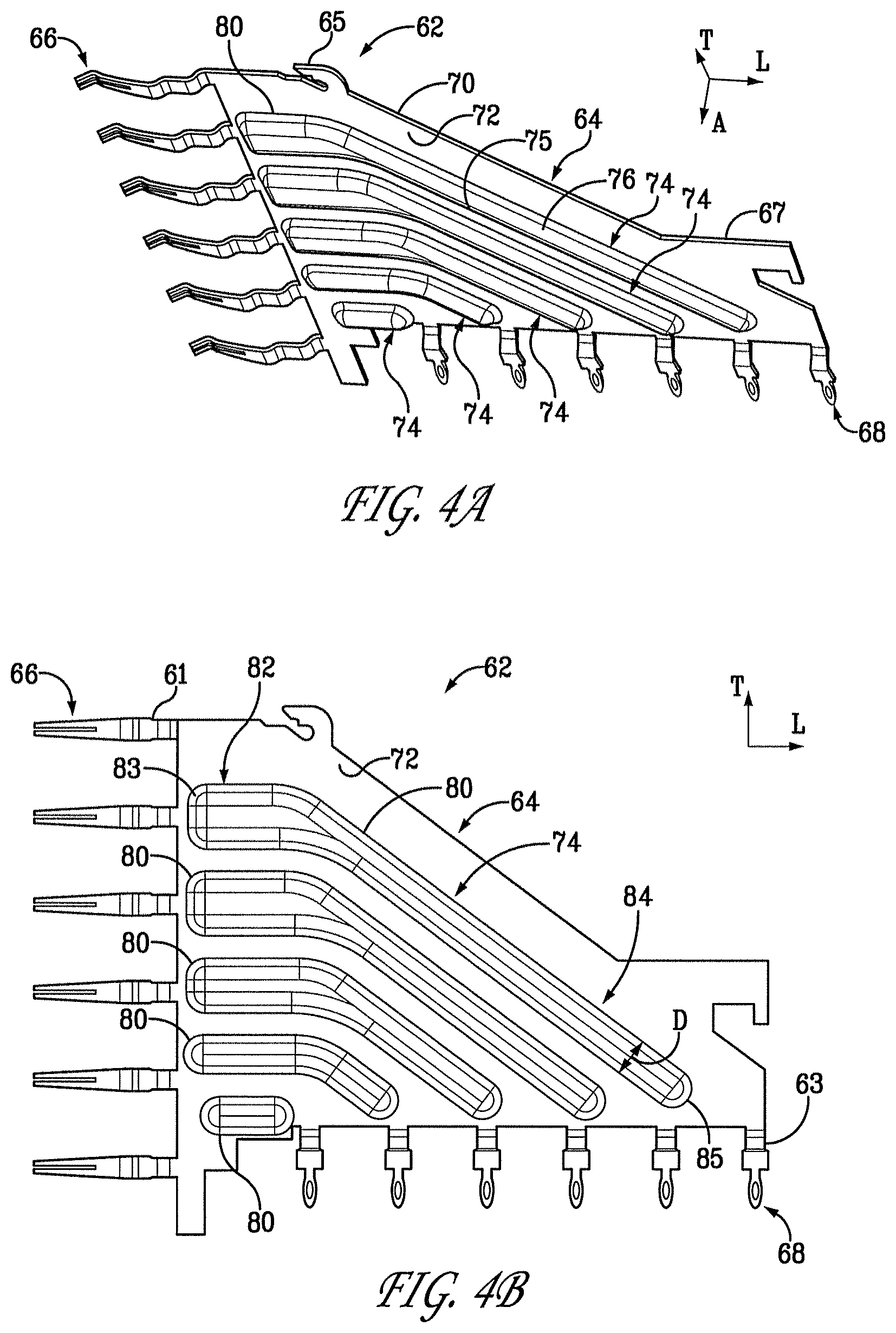
FIG. 4A is a perspective view of the ground plate illustrated in FIG. 3B;
FIG. 4B is a side elevation view of the ground plate illustrated in FIG. 4A;
FIG. 5A is a perspective view of the IMLA as illustrated in FIG. 3A but with the leadframe housing removed;
FIG. 5B is a perspective view of the IMLA as illustrated in FIG. 3B but with the leadframe housing removed;
FIG. 6A is a side elevation view of the IMLA illustrated in FIG. 3B;
FIG. 6B is a sectional view of the IMLA illustrated in FIG. 6A, taken along line 6B-6B;
FIG. 6C is a sectional view of the IMLA illustrated in FIG. 6A, taken along line 6C-6C;
FIG. 7A is a side elevation view of the electrical connector assembly as illustrated in FIG. 2B;
FIG. 7B is a sectional view of the electrical connector assembly illustrated in FIG. 7A, taken along line 7B-7B; and
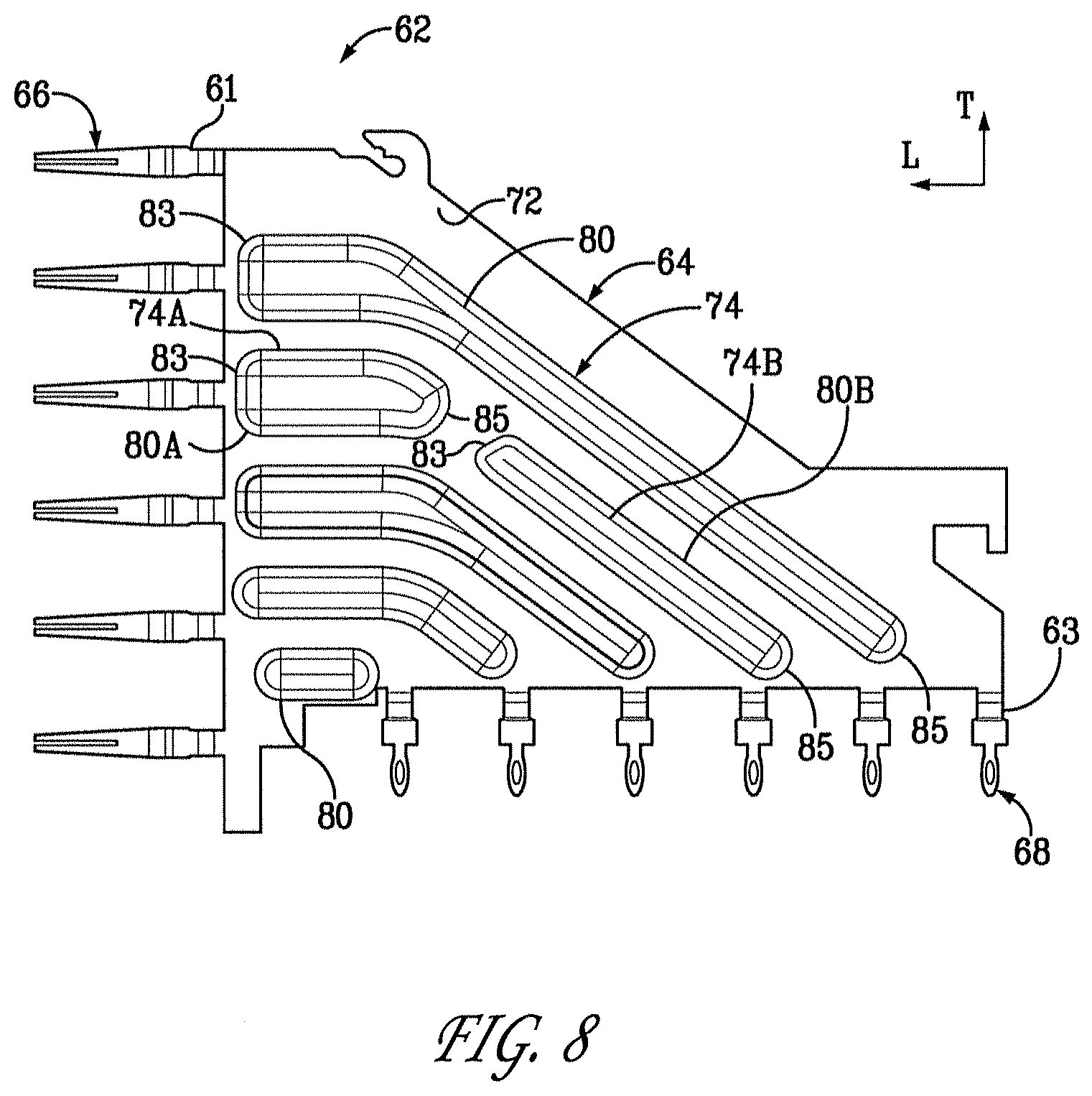
FIG. 8 is a side elevation view of a ground plate similar to the ground plate illustrated in FIG. 4B, but constructed in accordance with an alternative embodiment.
DETAILED DESCRIPTION
Referring initially to FIGS. 1-2B, an electrical connector assembly 20 includes a first electrical connector 22 and a second electrical connector 24 configured to mate with each other so as to establish an electrical connection between complementary substrates 38 and 42. As shown, the first electrical connector 22 can be a vertical connector defining a mating interface 26 and a mounting interface 28 that extends substantially parallel to the mating interface 26. The second electrical connector 24 can be a right-angle connector defining a mating interface 30 and a mounting interface 32 that extends substantially perpendicular to the mating interface 30.
The first electrical connector 22 includes a housing 31 that carries a plurality of electrical contacts 33. The electrical contacts 33 may be insert molded prior to attachment to the housing 31 or stitched into the housing 31. The electrical contacts 33 define respective mating ends 34 that extend along the mating interface 26, and mounting ends 36 that extend along the mounting interface 28. Each of the mating ends 34 can define a respective first broadside and a respective second broadside opposite the first broadside so as to define header mating ends. Thus, the first electrical connector 22 can be referred to as a header connector as illustrated. The mounting ends 36 may be press-fit tails, surface mount tails, or fusible elements such as solder balls, which are configured to electrically connect to a complementary electrical component such as a substrate 38 which is illustrated as a printed circuit board. The substrate 38 can be provided as a backplane, midplane, daughtercard, or the like.
Because the mating interface 26 is substantially parallel to the mounting interface 28, the first electrical connector 22 can be provided as a vertical connector, though it should be appreciated that the first electrical connector can be provided in any desired configuration so as to electrically connect the substrate 38 to the second electrical connector 24. For instance, the first electrical connector 22 can be provided as a header connector or a receptacle connector, and can be arranged as a vertical or mezzanine connector or a right-angle connector as desired.
With continuing reference to FIGS. 1-2B, the second electrical connector 24 includes a plurality of insert molded leadframe assemblies (IMLAs) 40 that are carried by an electrical connector housing 43. Each IMLA 40 carries a plurality of electrical contacts, such as right angle electrical contacts 44. Any suitable dielectric material, such as air or plastic, may be used to isolate the right angle electrical contacts 44 from one another. The right angle electrical contacts 44 define a respective receptacle mating ends 46 that extend along the mating interface 30, and a mounting ends 48 that extend along the mounting interface 32. Each mating end 46 extends horizontally forward along a longitudinal or first direction L, and the IMLAs 40 are arranged adjacent each other along a lateral or second direction A that is substantially perpendicular to the longitudinal direction L.
Each mounting end 48 extends vertically down along a transverse or third direction T that is perpendicular to both the lateral direction A and the longitudinal direction L. Thus, as illustrated, the longitudinal direction L and the lateral direction A extend horizontally as illustrated, and the transverse direction T extends vertically, though it should be appreciated that these directions may change depending, for instance, on the orientation of the electrical connector 24 during use. Unless otherwise specified herein, the terms "lateral," "longitudinal," and "transverse" as used to describe the orthogonal directional components of various components and do not limit to specific differential signal pair configurations. The terms "inboard" and "inner," and "outboard" and "outer" with respect to a specified directional component are used herein with respect to a given apparatus to refer to directions along the directional component toward and away from the center apparatus, respectively.
The receptacle mounting ends 48 may be constructed similar to the header mounting ends 36, and thus may include press-fit tails, surface mount tails, or fusible elements such as solder balls, which are configured to electrically connect to a complementary electrical component such as a substrate 42 which is illustrated as a printed circuit board. The substrate 42 can be provided as a backplane, midplane, daughtercard, or the like. The receptacle mating ends 46 are configured to electrically connect to the respective header mating ends 34 of the first electrical connector 22 when the respective mating interfaces 26 and 30 are engaged.
The right angle electrical contacts 44 may have a material thickness of about 0.1 mm to 0.5 mm and a contact height of about 0.1 mm to 0.9 mm. The contact height may vary over the length of the right angle electrical contacts 44. The second electrical connector 24 also may include an IMLA organizer 50 that may be electrically insulated or electrically conductive. An electrically conductive IMLA organizer 50 that retains the IMLAs 40 may be electrically connected to electrically conductive portions of the IMLAs 40 via slits 52 defined in the IMLA organizer 50 or any other suitable connection.
Because the mating interface 30 is substantially perpendicular to the mounting interface 32, the second electrical connector 24 can be provided as a right-angle connector, though it should be appreciated that the first electrical connector can be provided in any desired configuration so as to electrically connect the substrate 42 to the first electrical connector 22. For instance, the second electrical connector 24 can be provided as a receptacle connector or a header connector, and can be arranged as a vertical or mezzanine connector or a right-angle connector as desired. When the connectors 22 and 24 are mounted onto their respective substrates 38 and 42 and electrically connected to each other, the substrates are placed in electrical communication.
Referring now also to FIGS. 3A-C, Each IMLA 40 includes a leadframe housing 54 which can be provided as a dielectric housing that defines laterally opposed outer surfaces 71 and 73. The leadframe housing can be made of any suitable dielectric material such as plastic, and carries a plurality of electrical signal contacts 56 form right-angle contacts which can be overmolded by the housing 54, or can alternatively can be stitched or otherwise attached in the housing 54. Each signal contact 56 includes a mating end 58 and a mounting end 60. The mating ends 58 of the signal contacts 56 are aligned along the transverse direction T, and the mounting ends 60 of the signal contacts 56 are aligned along the longitudinal direction L. The signal contacts 56 are arranged in pairs 57 (see also FIGS. 6B-C), which can be differential signal pairs. Alternatively, the signal contacts 56 can be provided as single-ended signal contacts. One or more up to all of adjacent pairs 57 of signal contacts 56 are separated by a gap 59.
Each IMLA 40 further includes a ground plate 62 that is carried by the leadframe housing 54. The ground plate 62 can be formed from any suitable electrically conductive material, such as a metal, and includes a body 64, a plurality of mating ends 66 extending forward from the body 64, and a plurality of mounting ends 68 extending down from the body. The mating ends 66 and mounting ends 68 can be constructed as described above with respect to the mating ends 58 and 60 of the electrical signal contacts 56. The ground plate 62 can be discretely attached to the housing 54 or overmolded by the housing 54. Referring now also to FIGS. 4A-B, the body 64 of the ground plate 62 defines an inner or first surface 72 and an outer or second surface 70 that is laterally opposed with respect to the inner surface 72. The outer surface 70 can be flush with, can protrude past, or can be inwardly recessed with respect to the corresponding outer surface 71 of the leadframe housing 54. Accordingly, the dimensions of the electrical connector 24 can remain unchanged with respect to electrical connectors whose IMLAs carry discrete ground contacts, for instance as described in U.S. Pat. No. 7,497,736, the disclosure of which is hereby incorporated by reference as if set forth in its entirety herein. The inner surface 72 faces the electrical signal contacts 56 of the IMLA 40. The ground plate 62 can further include at least one engagement member configured to attach to the organizer, such as upper or first hook 65 and a rear or second hook 67.
The ground plate 62 can be electrically conductive, and thus configured to reflect electromagnetic energy produced by the signal contacts 56 during use, though it should be appreciated that the ground plate 62 could alternatively be configured to absorb electromagnetic energy. For instance the ground plate 62 can be made from one or more ECCOSORB.RTM. absorber products, commercially available from Emerson & Cuming, located in Randolph, Mass. The ground plate 62 can alternatively be made from one or more SRC Polylron.RTM. absorber products, commercially available from SRC Cables, Inc, located in Santa Rosa, Calif. Furthermore, the ground plates 62 are disposed between the signal contacts 56 of adjacent IMLAs, the ground plates 62 can provide a shield that reduces cross-talk between signal the signal contacts 56 of adjacent IMLAs 40.
The mating ends 66 of the ground plate 62 define ground mating ends, while the mounting ends 68 of the ground plate 62 define ground mounting ends. The mating ends 66 are aligned along the transverse direction T, and are further aligned with the mating ends 58 along the transverse direction T. The mounting ends 68 are aligned along the longitudinal direction L, and are aligned with the mounting ends 60 along the longitudinal direction L. The mating ends 66 are positioned adjacent and/or between pairs 57 of mating ends 58, and the mounting ends 68 are positioned adjacent and/or between pairs of mounting ends 60. Thus, the mating ends 46 of the electrical connector 24 include both the mating ends 58 and the mating ends 66, and the mounting ends 48 of the electrical connector 24 include both the mounting ends 60 and the mounting ends 68.
In accordance with the illustrated embodiment, the mating ends 66 of the ground plate 62 are disposed in the gap 59 that extends between adjacent pairs 57 of mating ends 58, such that the mating ends 46, which includes mating ends 58 and 66, are equidistantly spaced along the mating interface 30 of the electrical connector 24. Likewise, the mounting ends 68 of the ground plate 62 are disposed in the gap 59 that extends between adjacent pairs of mounting ends 60, such that the mounting ends 48, which includes the mounting ends 60 and 68, are equidistantly spaced along the mounting interface 32 of the electrical connector 24.
The pairs 57 of electrical signal contacts 56 may be differential signal pairs, or the signal contacts 56 can be provided as single-ended contacts. The signal contacts 56 are positioned edge-to-edge along a common centerline CL. Six differential signal pairs 57 are illustrated, however the connector 24 can include any number of differential signal pairs extending along the centerline CL, such as two, three, four, five, six, or more.
Referring now to FIGS. 4A-5B, the ground plate 62 includes at least one rib 74, such as a plurality of ribs 74 supported by the plate body 64. In accordance with the illustrated embodiment, each rib 74 is stamped or embossed into the body 64, and is thus integral with the body 64. Thus, the ribs 74 can further be referred to as embossments. As illustrated, each rib 74 defines a first surface 75 that defines a projection 76 extending laterally inwardly (e.g., into the IMLA 40) from the inner surface 72, and an opposed second surface 77 that defines a corresponding divot 78 or recessed surface extending into the outer surface 70 of the ground plate body 64. Otherwise stated, the body 64 includes a plurality of projections 76 projecting laterally from the inner surface, and further includes a plurality of divots 78, corresponding to the plurality of projections 76, recessed in the outer surface 70. The ribs 74 define respective enclosed outer perimeters 80 that are spaced from each other along the ground plate body 64. Thus, the ribs 74 are fully contained in the plate body 64.
The ribs 74 define a front or first portion 82 disposed proximate to the mating ends 66, and a rear or second portion 84 that is disposed proximate to the mounting ends 68. The front and rear portions 82 and 84 define a respective front or first terminal end 83, and a rear or second terminal end 85. The ribs 74 thus define a length extending between the first end second terminal ends 83 and 85. As illustrated, the ribs 74 can have different lengths along the ground plate body 64. For instance, those ribs 74 disposed at an upper or first end of the ground plate body 64 are longer than the ribs 74 that are disposed at a lower or second end of the ground plate body 64. In accordance with the illustrated embodiment, the length of each ribs 74 decreases along a direction from the upper or first end to the lower or second end of the ground plate body 64.
The ribs 74 can extend along a direction that includes one or more of a horizontal or longitudinal direction, a vertical or transverse direction, and an angled direction having both longitudinal and transverse directional components. For instance, as illustrated, the front portions 82 of some of the ribs 74 extend along a longitudinal rearward or direction from a location proximate to the mating ends 66 to the rear portion 84. The rear portion 84 extends along a second direction that is laterally rearward and transversely down from the front portion 82 to a location proximate to the mounting ends 68. The rear portion 84 extends at an angle between 90.degree. and 180.degree. with respect to the front portion 82. It should be appreciated that one or more of the ribs 74, for instance the bottommost rib 74 shown in FIG. 4B, extends only longitudinally. It should be further appreciated that one or more of the ribs 74 can further extend along a third transverse direction, for instance at a location proximate to the mounting ends 68.
Referring now to FIGS. 4A-6C, the electrical signal contacts 56 are aligned or arranged in a first transverse-longitudinal plane T-L1 that includes the common centerline CL, and the ground plate body 64 is oriented in a second transverse-longitudinal ground plane T-L2 that extends substantially parallel to the first plane T-L1, and is laterally outwardly offset or spaced from the first plane T-L1. The projection 76 of each rib 74 extends laterally inward from the inner surface 72 of the ground plate body 64 toward the first plane T-L1. The projections 76 can extend laterally from the inner surface 72 a distance sufficient such that a portion of each projections 76 extends into the first plane T-L1 and is thus co-planar with the signal contacts 56 (or a portion of the signal contacts 56), but less than the thickness of the leadframe housing 54 such that the projections 76 are recessed with respect to the outer surface 73 (see FIG. 3B). The projections 76 are aligned with the gaps 59 disposed between adjacent pairs 57 of signal contacts 56, such that the portion of each projection 76 that extends into the first plane T-L1 between adjacent pairs 57 is disposed in a corresponding one of the gaps 59.
The ground plate 62 includes a first neck 61 extending between the ground plate body 64 and each mating end 66, and a second neck 63 extending between the ground plate body 64 and each mounting end 68. In particular, each first neck 61 extends laterally inward from the second plane T-L2 toward the first plane T-L1 along a longitudinally forward direction from the ground plate body 64, such that the mating ends 66 lie in the first plane T-L1 and are thus co-planar with the mating ends 58 of the signal contacts 56. Likewise, the second neck 63 extends laterally inward from the second plane T-L2 toward the first plane T-L1 along a transversely downward direction from the ground plate body 64, such that the mounting end 68 lies in the first plane T-L1, and is thus co-planar with the mounting ends 60 of the signal contacts 56.
Each rib 74 defines a cross-sectional distance D that extends along the second plane T-L2 in a direction normal to the outer perimeter 80. The distance D can be consistent along the length of a given rib 74, as illustrated in the lowermost rib 74 shown in FIG. 4A. Alternatively, the distance D can vary along the length of a given rib between the front and rear ends 83 and 85, respectively. For instance, the distance D can be smaller at the rear portion 84 than at the front portion 82. Otherwise stated, the distance D can increase along the length of the rib 74 from the rear portion 84 to the front portion 82. Likewise, the gap 59 disposed between adjacent pairs 57 of signal contacts 56 can increase along a direction from the mounting ends 60 toward the mating ends 58 so as to accommodate the increasing cross-sectional distance D of the ribs 74.
With continuing reference to FIGS. 4A-6C, and in particular to FIGS. 6B-C, each rib 74 can include at least one wall 88. The wall 88 includes opposed outer wall portions 90 that each extend laterally from the inner surface 72 at the outer perimeter 80, and can converge toward each other along their direction of extension from the inner surface 72. When the ground plate 62 is installed in the IMLA, the outer wall portions 90 extend into a corresponding one of the gaps 59 between adjacent pairs 57 of signal contacts 56. As illustrated, the outer wall portions 90 can be beveled or curved. Furthermore, the curvature of each rib 74 can vary along its length. The outer wall portions 90 define from a proximal end 92 of the rib 74, and terminate at a middle wall portion 96 that is connected between the outer wall portions 90. The proximal end 92 of the rib 74 is the portion of the rib 74 that extends from the inner surface 72 at a location proximate to the inner surface 72.
The middle wall portion 96 is thus disposed at a location that is laterally offset with respect to the inner surface 72 of the ground plate body 64. In accordance with the illustrated embodiment, the middle wall portion 96 defines a distal end 98 of the rib 74 that lies in the first plane T-L1. The middle wall portion 96 can include a curved portion along a direction extending normal to the signal contacts 56 that define the corresponding gap 59, or can alternatively or additionally include a flat portion along a direction extending normal to the signal contacts 56 that define the gap 59. In this regard, it should be appreciated that the middle wall portion 96 can alternatively be entirely curved along a direction extending normal to the signal contacts 56 that define the corresponding gap 59, or entirely flat along a direction extending normal to the signal contacts 56 that define the gap 59. Thus, the ribs 74 can define curvatures that vary from each other. It should thus be appreciated that the ribs 74 can be curved or tapered, and thus devoid of sharp edges that are out of plane T-L1 with respect to the differential signal contacts 56. Furthermore, each rib 74 can be spaced at a consistent distance along its length from its adjacent signal contacts 56 that define the corresponding gap 59. Moreover, each rib 74 can be spaced from its adjacent signal contacts 56 a distance that is substantially equal to the distance that one or more up to all of the other ribs 74 are spaced from their adjacent signal contacts.
While the middle wall portion 96 can lie in the first plane T-L1 as illustrated, it should be appreciated that the rib 74 could alternatively terminate at the distal end 98 which is positioned inward of, or past, the first plane T-L1. In accordance with the illustrated embodiment, the middle wall portion 96 extends at substantially a constant lateral distance LD from the inner surface 72 of the ground plate 62 that is substantially equal to the lateral distance between the second plane T-L2 and the first plane T-L1.
It should be appreciated that a portion of each rib 74 can overlap the electrical signal contacts 56 that define the corresponding gap 59 with respect to an axis extending through the signal contacts 56 in a direction perpendicular to and between the first and second planes T-L1 and T-L2. Alternatively, the ribs 74 can be wholly contained between the axes extending through the signal contacts 56 in a direction perpendicular to and between the first and second planes T-L1 and T-L2. For instance, In accordance with the illustrated embodiment, the proximal end 92 of each rib 74 is positioned inward with respect to the corresponding signal contacts 56 that define the gap 59. Accordingly, a lateral axis L1 that extends through the proximal ends 92 one or more ribs 74 also extends through the corresponding gap 59, and not one of the signal contacts 56 that defines the gap 59. Alternatively, the proximal ends 92 could be disposed outward or inline with respect to the corresponding signal contacts 56 that define the gap 59. Accordingly, the lateral axis L1 that extends through the proximal ends 92 or other locations of the rib 74 can also extend through one or both signal contacts 56 that defines the corresponding gap 59.
With continuing reference to FIGS. 4A-6C, each rib 74 can define a first width W1 extending along a direction parallel to the ground plate plane T-L2 at the proximal end 92, and a second width W2 extending along the direction parallel to the ground plate plane T-L2 at the distal end 98 that is less than the first width W1 in accordance with the illustrated embodiment. The widths W1 and W2 of at least one rib 74 can be less than, greater than, or substantially equal to one or both of the corresponding widths W1 and W2 of one or more of the other ribs 74.
While the ribs 74 are illustrated as extending continuously from their respective front end 83 to their rear ends 85, it should be appreciated that one or more up to all of the ribs 74 can be discontinuous or segmented between the front and rear ends 83 and 85. For instance, as illustrated in FIG. 8, one or more the ribs 74 can be provided as separate rib segments 74a and 74b, each defining respective enclosed perimeters 80a and 80b spaced from each other between the corresponding mating end 66 and mounting end 68. Alternatively or additionally, the middle wall portion 96 of a given rib 74 can project a distance from the inner surface 72 that varies along the length of the rib 74 between the front end 83 and the rear end 85.
While FIGS. 6B-C show the leadframe housing 54 overmolded onto the signal contacts 56 and the ground plate 62, it should be appreciated that the signal contacts 56, the ground plate 62, or both the signal contacts 56 and the ground plate 62 can be discreetly attached to the leadframe housing 54. Furthermore, while the ground plate 62 is shown as abutting the leadframe housing 54 along its length, the ground plate 62 can alternatively be supported by the leadframe housing 54 at discrete locations of the ground plate 62, such that one or more air gaps are disposed between the housing 54 and the ground plate 62 and desired locations. For instance, an air gap between the leadframe housing 54 and the ribs 74 would allow for clearance of the ribs 74 when the ground plate 62 is attached to the leadframe housing 54. It should be further appreciated that such air gaps could further be provided when the leadframe housing 54 is overmolded onto the ground plate 62. Likewise, while the signal contacts 56 are shown as abutting the leadframe housing 54 along their length, the signal contacts 56 can alternatively be supported by the leadframe housing 54 at discrete locations of the signal contacts 56, such that air gaps are disposed between the housing 54 and the signal contacts and desired locations. It should be further appreciated that such air gaps could further be provided when the leadframe housing 54 is overmolded onto the signal contacts 56.
Referring now to FIGS. 7A-B, the electrical connector 24 is illustrated as including a plurality of IMLAs 40 of the type described above. Four IMLAs 40 are illustrated having electrical contacts 44 that extend along respective common centerlines CL, though it should be appreciated that the connector 24 can include as many IMLAs 40 as desired. Each IMLA can include as many electrical signal contact pairs 57 and interleaved ribs 74 as desired. Thus, one or more up to all of the IMLAs 40 can include a ground plate 62 of the type described above. The IMLAs 40 include a first-type of IMLAs 40A that are substantially identically constructed and a second type of IMLAs 40B that substantially identically constructed. The IMLAs 40A and 40B are alternately arranged along the lateral direction A. In accordance with the illustrated embodiment, the signal contacts 56 of the first IMLAs 40A are staggered with respect to the signal contacts 56 of the second IMLAs 40B. Accordingly, the gaps 59 between adjacent signal pairs 57 of the first IMLAs 40a are staggered with respect to the gaps 59 of the second IMLAs 40B. It should be appreciated that the mating ends 66 and mounting ends 68 can extend from any position along the ground plate body 64 as desired, such that the mating ends 66 are disposed between and aligned with the mating ends 58 of the signal contacts 56 in the manner described above, and the mounting ends 68 are disposed between and aligned with the mounting ends 60 of the signal contacts 56 in the manner described above.
For instance, in accordance with one embodiment, the mating ends 46 of the first IMLAs 40A are arranged in a repeating G-S-S-G-S-S pattern in a direction along the common centerline CL from the top of the mating interface 30 toward the bottom of the mating interface 30, whereby "G" denotes electrical ground contact mating ends 66 and "S" denotes electrical signal contact mating ends 58. Furthermore, in accordance with one embodiment, the mating ends 46 of the second IMLAs 40B are arranged in a repeating S-S-G-S-S-G pattern in a direction along the common centerline CL from the top end of the mating interface 30 toward the bottom of the mating interface 30, whereby "G" denotes electrical ground contact mating ends 66 and "S" denotes electrical signal contact mating ends 58.
It should thus be appreciated that a method of producing an electrical connector includes the steps of 1) providing a plurality of electrical signal contacts 56, 2) retaining the electrical signal contacts 56 in the leadframe housing 54 along the first plane T-L1 so as to define gaps 59 disposed between adjacent pairs of electrical signal contacts 56, 3) providing a ground plate 62 having a ground plate body 64 that defines first and second opposed surfaces 72 and 70, respectively, 4) stamping a plurality of ribs 74 into the second surface 70 of the ground plate body 64 such that the ribs 74 define first and second opposed surfaces 75 and 77, respectively, wherein the first surface 75 of each rib 74 projects out from the first surface 72 of the ground plate body 64, and the second surface 77 of each rib is recessed in the second surface 70 of the ground plate body 64, and 5) attaching the ground plate 62 to the leadframe housing 54 such that the ground plate body 64 is oriented in the second plane T-L2 that is offset with respect to the first plane T-L1, and the first surface 75 of each rib 74 projects toward a respective one of the gaps 59 defined by the adjacent pairs 57 of electrical signal contacts 56.
The ground plate 62 is a wide continuous conductor, and is wider than the ground contacts of an electrical connector that is substantially identical with respect to the electrical connector 24, with the exception that the substantially identical electrical connector does not include the ground plate 62, but instead includes discrete ground contacts extending in the gaps 59 that define opposing ground mating ends and ground mounting ends as described in U.S. Pat. No. 7,497,736. Accordingly, it should be appreciated that the electrical connector 24 can be modified with respect to substantially identical electrical connector, with the exception that the electrical connector 24 is devoid of discrete ground contacts in favor of the ground plate 62 having ribs 74 that extend between adjacent pairs 57 of signal contacts 56. Thus, the electrical connector 24 is an improvement over shieldless, high density, right-angle electrical connectors that have discrete ground contacts without significantly lowering impedance matching and without significantly increasing inductance. In accordance with embodiments of the present invention, the impedance of the electrical connector 24 is not significantly altered with respect to a pre-modified connector, inductance of the electrical connector 24 is lower than the ground contacts in the same pre-modified connector, crosstalk of the electrical connector 24 is lower as compared to the same pre-modified connector, and the overall dimensions of the electrical connector 24 are the same as those of the pre-modified connector.
For instance, it is believed that the ground plate 62 provides a low-impedance common path that intercepts and dissipates stray electro-magnetic energy between signal contacts 56 that otherwise would have been a source for cross talk. It is believed that a connector that incorporates the IMLAs 40 as described above can operate at 13 GHz with acceptable worst-case, multi-active crosstalk on a victim pair of no more than six percent, for instance less than one percent, such as 0.4 percent. Worst case, multi-active crosstalk may be determined in the manner described in U.S. Pat. No. 7,497,736.
The foregoing description is provided for the purpose of explanation and is not to be construed as limiting the invention. While various embodiments have been described with reference to preferred embodiments or preferred methods, it is understood that the words which have been used herein are words of description and illustration, rather than words of limitation. Furthermore, although the embodiments have been described herein with reference to particular structure, methods, and embodiments, the invention is not intended to be limited to the particulars disclosed herein. Those skilled in the relevant art, having the benefit of the teachings of this specification, may effect numerous modifications to the invention as described herein, and changes may be made without departing from the spirit and scope of the invention as defined by the appended claims.
* * * * *
References
-
molex.com/link/Impact.html
-
amphenol-tcs.com/products/connectors/backplane/index.html
-
-
teradyne.com/prods/tcs/products/connectors/mezzanine/hdmstacker/sidnintegrity.html
-
-
samtec.com
-
tycoelectronics.com/catalog
-
xenpak.org
-
epn-online.com/pade/new59327/tyco-unveils-z-pack-orthogonal-conn
-
-
-
-
-
amphenoltcs.com/products/connectors/backplane/xcede/index.htm-1
-
2dok.tyco.electronics.com
-
ww.zpackuhd.com
-
4spe.org
-
plasticstechnology.com
D00000
D00001
D00002
D00003
D00004
D00005
D00006
D00007
D00008
D00009
D00010
D00011
XML
uspto.report is an independent third-party trademark research tool that is not affiliated, endorsed, or sponsored by the United States Patent and Trademark Office (USPTO) or any other governmental organization. The information provided by uspto.report is based on publicly available data at the time of writing and is intended for informational purposes only.
While we strive to provide accurate and up-to-date information, we do not guarantee the accuracy, completeness, reliability, or suitability of the information displayed on this site. The use of this site is at your own risk. Any reliance you place on such information is therefore strictly at your own risk.
All official trademark data, including owner information, should be verified by visiting the official USPTO website at www.uspto.gov. This site is not intended to replace professional legal advice and should not be used as a substitute for consulting with a legal professional who is knowledgeable about trademark law.