Intercooled cooling air with low temperature bearing compartment air
Schwarz , et al.
U.S. patent number 10,718,233 [Application Number 16/012,152] was granted by the patent office on 2020-07-21 for intercooled cooling air with low temperature bearing compartment air. This patent grant is currently assigned to Raytheon Technologies Corporation. The grantee listed for this patent is United Technologies Corporation. Invention is credited to Glenn Levasseur, Brian D. Merry, Frederick M. Schwarz.


| United States Patent | 10,718,233 |
| Schwarz , et al. | July 21, 2020 |
Intercooled cooling air with low temperature bearing compartment air
Abstract
A gas turbine engine includes a plurality of rotatable components housed within a main compressor section and a turbine section. A cooling system is connected to tap air from said main compressor section. A first tap is connected to a first heat exchanger. The first heat exchanger is connected to a cooling compressor for raising a pressure of the tapped air downstream of the first heat exchanger. A second heat exchanger is downstream of the cooling compressor, and a connection is downstream of the second heat exchanger for delivering air to a bearing compartment. A connection intermediate the cooling compressor and the second heat exchanger delivers cooling air to at least one of the rotatable components.
| Inventors: | Schwarz; Frederick M. (Glastonbury, CT), Levasseur; Glenn (Colchester, CT), Merry; Brian D. (Andover, CT) | ||||||||||
|---|---|---|---|---|---|---|---|---|---|---|---|
| Applicant: |
|
||||||||||
| Assignee: | Raytheon Technologies
Corporation (Farmington, CT) |
||||||||||
| Family ID: | 67105687 | ||||||||||
| Appl. No.: | 16/012,152 | ||||||||||
| Filed: | June 19, 2018 |
Prior Publication Data
| Document Identifier | Publication Date | |
|---|---|---|
| US 20190383167 A1 | Dec 19, 2019 | |
| Current U.S. Class: | 1/1 |
| Current CPC Class: | F04D 29/582 (20130101); F02C 9/18 (20130101); F02C 7/18 (20130101); F02C 7/185 (20130101); F02C 6/08 (20130101); F01D 25/125 (20130101); F02C 7/06 (20130101); F05D 2260/213 (20130101); Y02T 50/60 (20130101); F05D 2260/211 (20130101); F05D 2220/323 (20130101); F02K 3/06 (20130101); F05D 2270/303 (20130101); F05D 2240/50 (20130101) |
| Current International Class: | F02C 7/18 (20060101); F01D 25/12 (20060101); F04D 29/58 (20060101); F02K 3/06 (20060101) |
References Cited [Referenced By]
U.S. Patent Documents
| 2692476 | October 1954 | Schaal et al. |
| 3878677 | April 1975 | Colvin |
| 4254618 | March 1981 | Lovic |
| 4539945 | September 1985 | Bosisio |
| 4882902 | November 1989 | Reigel et al. |
| 5056335 | October 1991 | Enninger et al. |
| 5269135 | December 1993 | Vermejan et al. |
| 5305616 | April 1994 | Coffinberry |
| 5392614 | February 1995 | Coffinberry |
| 5414992 | May 1995 | Glickstein |
| 5452573 | September 1995 | Glickstein et al. |
| 5498126 | March 1996 | Pighetti et al. |
| 5724806 | March 1998 | Horner |
| 5758485 | June 1998 | Frutschi |
| 5867979 | February 1999 | Newton et al. |
| 5918458 | July 1999 | Coffinberry et al. |
| 6050079 | April 2000 | Durgin et al. |
| 6065282 | May 2000 | Fukue et al. |
| 6134880 | October 2000 | Yoshinaka |
| 6430931 | August 2002 | Horner |
| 6487863 | December 2002 | Chen et al. |
| 6584778 | July 2003 | Griffiths et al. |
| 6612114 | September 2003 | Klingels |
| 6892523 | May 2005 | Fetescu et al. |
| 7237386 | July 2007 | Hoffmann et al. |
| 7246484 | July 2007 | Giffin, III et al. |
| 7284377 | October 2007 | Joshi et al. |
| 7306424 | December 2007 | Romanov et al. |
| 7334412 | February 2008 | Tiemann |
| 7347637 | March 2008 | Kubo et al. |
| 7500365 | March 2009 | Suciu et al. |
| 7552591 | June 2009 | Bart et al. |
| 7698884 | April 2010 | Maguire et al. |
| 7765788 | August 2010 | Schwarz |
| 7823389 | November 2010 | Seltzer et al. |
| 7882691 | February 2011 | Lemmers, Jr. et al. |
| 7886520 | February 2011 | Stretton et al. |
| 8015828 | September 2011 | Moniz et al. |
| 8037686 | October 2011 | Lasker |
| 8087249 | January 2012 | Ottaviano et al. |
| 8181443 | May 2012 | Rago |
| 8307662 | November 2012 | Turco |
| 8350398 | January 2013 | Butt |
| 8397487 | March 2013 | Sennoun et al. |
| 8402742 | March 2013 | Roberge et al. |
| 8434997 | May 2013 | Pinero et al. |
| 8511967 | August 2013 | Suciu et al. |
| 8522529 | September 2013 | Martinou et al. |
| 8572982 | November 2013 | Tiemann |
| 8602717 | December 2013 | Suciu et al. |
| 8621871 | January 2014 | McCune et al. |
| 8727703 | May 2014 | Laurello et al. |
| 8776952 | July 2014 | Schwarz et al. |
| 8814502 | August 2014 | Eleftheriou |
| 8876465 | November 2014 | Stretton |
| 8961108 | February 2015 | Bergman et al. |
| 9234481 | January 2016 | Suciu et al. |
| 9243563 | January 2016 | Lo |
| 9255492 | February 2016 | Bacic |
| 9297391 | March 2016 | Rued et al. |
| 9422063 | August 2016 | Diaz |
| 9429072 | August 2016 | Diaz et al. |
| 2003/0046938 | March 2003 | Mortzheim et al. |
| 2004/0088995 | May 2004 | Reissig |
| 2005/0172612 | August 2005 | Yamanaka et al. |
| 2007/0022735 | February 2007 | Henry et al. |
| 2007/0213917 | September 2007 | Bruno et al. |
| 2007/0245738 | October 2007 | Stretton et al. |
| 2008/0028763 | February 2008 | Schwarz et al. |
| 2008/0230651 | September 2008 | Porte |
| 2008/0253881 | October 2008 | Richards |
| 2009/0007567 | January 2009 | Porte et al. |
| 2009/0090096 | April 2009 | Sheridan |
| 2009/0145102 | June 2009 | Roberge et al. |
| 2009/0196736 | August 2009 | Sengar et al. |
| 2009/0226297 | September 2009 | Yanagi et al. |
| 2009/0272120 | November 2009 | Tiemann |
| 2010/0043396 | February 2010 | Coffinberry |
| 2010/0154434 | June 2010 | Kubota et al. |
| 2011/0036066 | February 2011 | Zhang et al. |
| 2011/0088405 | April 2011 | Turco |
| 2011/0120083 | May 2011 | Giffin et al. |
| 2011/0247344 | October 2011 | Glahn et al. |
| 2012/0067055 | March 2012 | Held |
| 2012/0102915 | May 2012 | Baltas |
| 2012/0159961 | June 2012 | Krautheim et al. |
| 2012/0180509 | July 2012 | DeFrancesco |
| 2013/0036747 | February 2013 | Fuchs et al. |
| 2013/0067928 | March 2013 | Arias Chao et al. |
| 2013/0098059 | April 2013 | Suciu et al. |
| 2013/0145744 | June 2013 | Lo et al. |
| 2013/0145774 | June 2013 | Duong et al. |
| 2013/0186102 | July 2013 | Lo |
| 2013/0199156 | August 2013 | Ress, Jr. et al. |
| 2013/0239583 | September 2013 | Suciu et al. |
| 2013/0319002 | December 2013 | Sidelkovskiy et al. |
| 2014/0020506 | January 2014 | Duong |
| 2014/0137417 | May 2014 | Silberberg et al. |
| 2014/0196469 | July 2014 | Finney et al. |
| 2014/0230444 | August 2014 | Hao et al. |
| 2014/0250898 | September 2014 | Mackin et al. |
| 2014/0260326 | September 2014 | Schwarz et al. |
| 2014/0311157 | October 2014 | Laurello et al. |
| 2014/0341704 | November 2014 | Fletcher |
| 2014/0352315 | December 2014 | Diaz |
| 2015/0114611 | April 2015 | Morris et al. |
| 2015/0285147 | October 2015 | Phillips et al. |
| 2015/0308339 | October 2015 | Forcier |
| 2015/0330236 | November 2015 | Beecroft et al. |
| 2015/0354465 | December 2015 | Suciu et al. |
| 2015/0354822 | December 2015 | Suciu et al. |
| 2016/0010554 | January 2016 | Suciu et al. |
| 2016/0131036 | May 2016 | Bintz et al. |
| 2016/0131037 | May 2016 | Spangler et al. |
| 2016/0169118 | June 2016 | Duong |
| 2016/0215732 | July 2016 | Malecki |
| 2016/0237906 | August 2016 | Suciu et al. |
| 2016/0312711 | October 2016 | Suciu et al. |
| 2016/0312797 | October 2016 | Suciu et al. |
| 2016/0341125 | November 2016 | Kraft et al. |
| 2016/0369697 | December 2016 | Schwarz et al. |
| 2017/0009657 | January 2017 | Schwarz et al. |
| 2017/0044980 | February 2017 | Duesler et al. |
| 2017/0044982 | February 2017 | Duesler et al. |
| 2017/0152765 | June 2017 | Uechi et al. |
| 2017/0159568 | June 2017 | Sennoun et al. |
| 2017/0167388 | June 2017 | Merry et al. |
| 2017/0175632 | June 2017 | Hanrahan et al. |
| 2017/0184027 | June 2017 | Moniz et al. |
| 2017/0204787 | July 2017 | Duesler et al. |
| 2017/0284305 | October 2017 | Suciu et al. |
| 2852057 | Jun 1979 | DE | |||
| 102012208263 | Nov 2013 | DE | |||
| 0447886 | Sep 1991 | EP | |||
| 0469825 | Feb 1992 | EP | |||
| 0608142 | Jul 1994 | EP | |||
| 0903484 | Mar 1999 | EP | |||
| 1314872 | May 2003 | EP | |||
| 1944475 | Jul 2008 | EP | |||
| 2085599 | Aug 2009 | EP | |||
| 2128023 | Dec 2009 | EP | |||
| 2362081 | Aug 2011 | EP | |||
| 2540991 | Jan 2013 | EP | |||
| 2565392 | Mar 2013 | EP | |||
| 2584172 | Apr 2013 | EP | |||
| 2604825 | Jun 2013 | EP | |||
| 2733322 | May 2014 | EP | |||
| 2865981 | Apr 2015 | EP | |||
| 2942490 | Nov 2015 | EP | |||
| 3085923 | Oct 2016 | EP | |||
| 3085924 | Oct 2016 | EP | |||
| 3109438 | Dec 2016 | EP | |||
| 3121411 | Jan 2017 | EP | |||
| 2851295 | Aug 2004 | FR | |||
| 1244340 | Aug 1971 | GB | |||
| 2152148 | Jul 1985 | GB | |||
| H1136889 | Feb 1999 | JP | |||
| 2003037715 | May 2003 | WO | |||
| 2008082335 | Jul 2008 | WO | |||
| 2013154631 | Oct 2013 | WO | |||
| 2014046713 | Mar 2014 | WO | |||
| 2014092777 | Jun 2014 | WO | |||
| 2014120125 | Aug 2014 | WO | |||
Other References
|
European Search Report for EP Application No. 19179765.3 dated Nov. 12, 2019. cited by applicant . Dornheim, Michael A., Rolls-Royce Trent 1000 to Drive Boeing 787 Accessories From IP Spool, Aviation Week & Space Technology, Mar. 28, 2005, p. 51, Los Angeles, CA. cited by applicant . U.S. Appl. No. 15/232,101. cited by applicant . U.S. Appl. No. 14/964,984. cited by applicant . U.S. Appl. No. 14/967,446. cited by applicant . U.S. Appl. No. 15/069,197. cited by applicant . U.S. Appl. No. 15/269,014. cited by applicant . U.S. Appl. No. 15/373,072. cited by applicant . European Search Report for European Application No. 16166707.6 dated Sep. 26, 2016. cited by applicant . European Search Report for European Application No. 16166724.1 dated Sep. 26, 2016. cited by applicant . European Search Report for European Patent Application No. 16154635.3 dated Jul. 6, 2016. cited by applicant . European Search Report for European Application No. 16155316.9 completed Jun. 30, 2016. cited by applicant . European Search Report for Application No. 16170021.6 dated Oct. 11, 2016. cited by applicant . European Search Report for Application No. 16174862.9 dated Nov. 7, 2016. cited by applicant . European Search Report for European Application No. 16175531.9 dated Nov. 15, 2016. cited by applicant . European Search Report for European Application No. 16175533.5 dated Nov. 15, 2016. cited by applicant . European Search Report for European Application No. 16175552.5 dated Nov. 17, 2016. cited by applicant . European Search Report for European Application No. 16175760.4 dated Nov. 16, 2016. cited by applicant . European Search Report for Application No. 16178207.3 dated Nov. 21, 2016. cited by applicant . European Search Report for European Application No. 16202876.5 dated Apr. 24, 2017. cited by applicant . European Search Report for European Application No. 16180657.5 dated Dec. 16, 2016. cited by applicant . European Search Report for EP Application No. 17160816.9 dated Jul. 21, 2017. cited by applicant. |
Primary Examiner: Sosnowski; David E
Assistant Examiner: Ribadeneyra; Theodore C
Attorney, Agent or Firm: Carlson, Gaskey & Olds, P.C.
Claims
The invention claimed is:
1. A gas turbine engine comprising: a plurality of rotatable components housed within a main compressor section and a turbine section; a cooling system connected to tap air from said main compressor section, a first tap connected to a first heat exchanger, said first heat exchanger connected to a cooling compressor for raising a pressure of the tapped air downstream of the first heat exchanger; and a second heat exchanger downstream of said cooling compressor, and a connection downstream of said second heat exchanger for delivering air to a bearing compartment, and a connection intermediate said cooling compressor and said second heat exchanger for delivering cooling air to at least one of said rotatable components.
2. The gas turbine engine as set forth in claim 1, wherein said first tap taps air from said main compressor section at a location upstream of a downstream most location in said main compressor section.
3. The gas turbine engine as set forth in claim 1, wherein said first and said second heat exchangers are positioned within a bypass duct in said gas turbine engine.
4. The gas turbine engine as set forth in claim 1, wherein said bearing compartment is radially inward of a combustor intermediate said main compressor section and said turbine section.
5. The gas turbine engine as set forth in claim 1, wherein said at least one rotatable component includes at least one rotor in said main compressor section.
6. The gas turbine engine as set forth in claim 5, wherein said at least one rotatable component also includes at least one rotor in said turbine section.
7. The gas turbine engine as set forth in claim 1, wherein said at least one rotatable component includes at least one rotor in said turbine section.
8. The gas turbine engine as set forth in claim 1, wherein a control is operable to stop operation of said cooling compressor.
9. The gas turbine engine as set forth in claim 8, wherein said control operates said cooling compressor at high power operation including take-off of said gas turbine engine and the cooling compressor operates at a discharge total pressure that is higher than a pressure at a downstream most location of the main compressor.
10. The gas turbine engine as set forth in claim 9, wherein said control stops operation of said cooling compressor at lower power operation including cruise.
11. The gas turbine engine as set forth in claim 8, wherein a second tap taps compressed air from a location in said main compressor section downstream of a location of said first tap, and is connected to supply air through a check valve to a passage leading downstream of said cooling compressor to said at least one rotatable component, at least when said cooling compression is stopped.
12. The gas turbine engine as set forth in claim 1, wherein air supplied to said bearing compartment is at a temperature lower than 800.degree. F. at a take-off condition engine.
13. The gas turbine engine as set forth in claim 1, wherein said bearing compartment is radially in a combustor section which is intermediate said main compressor section and said turbine section, and said bearing compartment includes a bearing supporting a high pressure shaft connecting a high pressure compressor rotor to a high pressure turbine rotor, with said high pressure compressor rotor and said high pressure turbine rotor including said at least one of said rotatable components.
14. The gas turbine engine as set forth in claim 13, wherein air downstream of said second heat exchanger passes into a junction, and a portion of air downstream of said second heat exchanger is connected to said bearing compartment, and a second portion of air downstream of said second heat exchanger is connected to a second use.
15. The gas turbine engine as set forth in claim 14, wherein said second use includes at least one of a second bearing component, and a downstream location within said turbine section.
16. The gas turbine engine as set forth in claim 1, wherein air downstream of said second heat exchanger passes into a junction, and a portion of air downstream of said second heat exchanger is connected to said bearing compartment, and a second portion of air downstream of said second heat exchanger is connected to a second use.
17. The gas turbine engine as set forth in claim 16, wherein said second use includes at least one of a second bearing component, and a downstream location within said turbine section.
18. A gas turbine engine comprising: a plurality of rotatable components housed within a main compressor section and a turbine section; a cooling system connected to tap air from said main compressor section, a tap connected to a first heat exchanger, means for raising a pressure of the tapped air downstream of the first heat exchanger; and a second heat exchanger downstream of said cooling compressor, and a connection downstream of said second heat exchanger and means for delivering air to a bearing compartment, and a connection intermediate said cooling compressor and said second heat exchanger for delivering cooling air to at least one of said rotatable components.
19. The gas turbine engine as set forth in claim 18, wherein said means for raising a pressure includes a cooling compressor and a pressure of said cooling compressor is higher than a pressure at a downstream most location of the main compressor section.
20. The gas turbine engine as set forth in claim 18, wherein a control selectively stops operation of said means for raising a pressure.
Description
BACKGROUND
This application relates to an intercooled cooling air for supplying cooling air for rotating components of a gas turbine engine and for also supplying cooling air to a bearing compartment.
Gas turbine engines are known and typically include a fan delivering air into a bypass duct as propulsion air, and further delivering air into a compressor. Air in the compressor is compressed and passed into a combustion section where it is mixed with fuel and ignited. Products of the combustion pass downstream over turbine rotors driving them to rotate. The turbine rotors, in turn, rotate the compressor and fan.
As known, rotating components in the gas turbine engine have temperature challenges. Thus, it is known to provide cooling air to those components. It has been proposed to utilize compressed air as the cooling air and to deliver it to rotating components in the gas turbine engine.
SUMMARY
A gas turbine engine includes a plurality of rotatable components housed within a main compressor section and a turbine section. A cooling system is connected to tap air from said main compressor section. A first tap is connected to a first heat exchanger. The first heat exchanger is connected to a cooling compressor for raising a pressure of the tapped air downstream of the first heat exchanger. A second heat exchanger is downstream of the cooling compressor, and a connection is downstream of the second heat exchanger for delivering air to a bearing compartment. A connection intermediate the cooling compressor and the second heat exchanger delivers cooling air to at least one of the rotatable components.
In another embodiment according to the previous embodiment, the first tap taps air from the main compressor section at a location upstream of a downstream most location in the main compressor section.
In another embodiment according to any of the previous embodiments, the first and the second heat exchangers are positioned within a bypass duct in said gas turbine engine.
In another embodiment according to any of the previous embodiments, the bearing compartment is radially inward of a combustor intermediate the main compressor section and the turbine section.
In another embodiment according to any of the previous embodiments, the at least one rotatable component includes at least one rotor in the main compressor section.
In another embodiment according to any of the previous embodiments, the at least one rotatable component also includes at least one rotor in the turbine section.
In another embodiment according to any of the previous embodiments, the at least one rotatable component includes at least one rotor in the turbine section.
In another embodiment according to any of the previous embodiments, a control is operable to stop operation of the cooling compressor.
In another embodiment according to any of the previous embodiments, the control operates the cooling compressor at high power operation including take-off of the gas turbine engine and the cooling compressor operates at a discharge total pressure that is higher than a pressure at a downstream most location of the main compressor.
In another embodiment according to any of the previous embodiments, the control stops operation of the cooling compressor at lower power operation including cruise.
In another embodiment according to any of the previous embodiments, a second tap taps compressed air from a location in the main compressor section downstream of a location of the first tap, and is connected to supply air through a check valve to a passage leading downstream of the cooling compressor to the at least one rotatable component, at least when the cooling compression is stopped.
In another embodiment according to any of the previous embodiments, air supplied to the bearing compartment is at a temperature lower than 800.degree. F. at a take-off condition engine.
In another embodiment according to any of the previous embodiments, the bearing compartment is radially in a combustor section which is intermediate the main compressor section and the turbine section. The bearing compartment includes a bearing supporting a high pressure shaft connecting a high pressure compressor rotor to a high pressure turbine rotor, with said high pressure compressor rotor and the high pressure turbine rotor including the at least one of said rotatable components.
In another embodiment according to any of the previous embodiments, air downstream of the second heat exchanger passes into a junction, and a portion of air downstream of the second heat exchanger is connected to the bearing compartment, and a second portion of air downstream of the second heat exchanger is connected to a second use.
In another embodiment according to any of the previous embodiments, the second use includes at least one of a second bearing component, and a downstream location within the turbine section.
In another featured embodiment, a gas turbine engine includes a plurality of rotatable components housed within a main compressor section and a turbine section. A cooling system is connected to tap air from the main compressor section. A tap is connected to a first heat exchanger. There is a means for raising a pressure of the tapped air downstream of the first heat exchanger. A second heat exchanger is downstream of the cooling compressor. A connection is downstream of the second heat exchanger and there is a means for delivering air to a bearing compartment. A connection intermediate the cooling compressor and the second heat exchanger delivers cooling air to at least one of the rotatable components.
In another embodiment according to the previous embodiment, the means for raising a pressure includes a cooling compressor and a pressure of the cooling compressor is higher than a pressure at a downstream most location of the main compressor section.
In another embodiment according to any of the previous embodiments, a control selectively stops operation of the means for raising a pressure.
These and other features may be best understood from the following drawings and specification.
BRIEF DESCRIPTION OF THE DRAWINGS
FIG. 1 schematically shows a gas turbine engine.
FIG. 2 shows a first schematic system.
FIG. 3 shows a second embodiment schematic system.
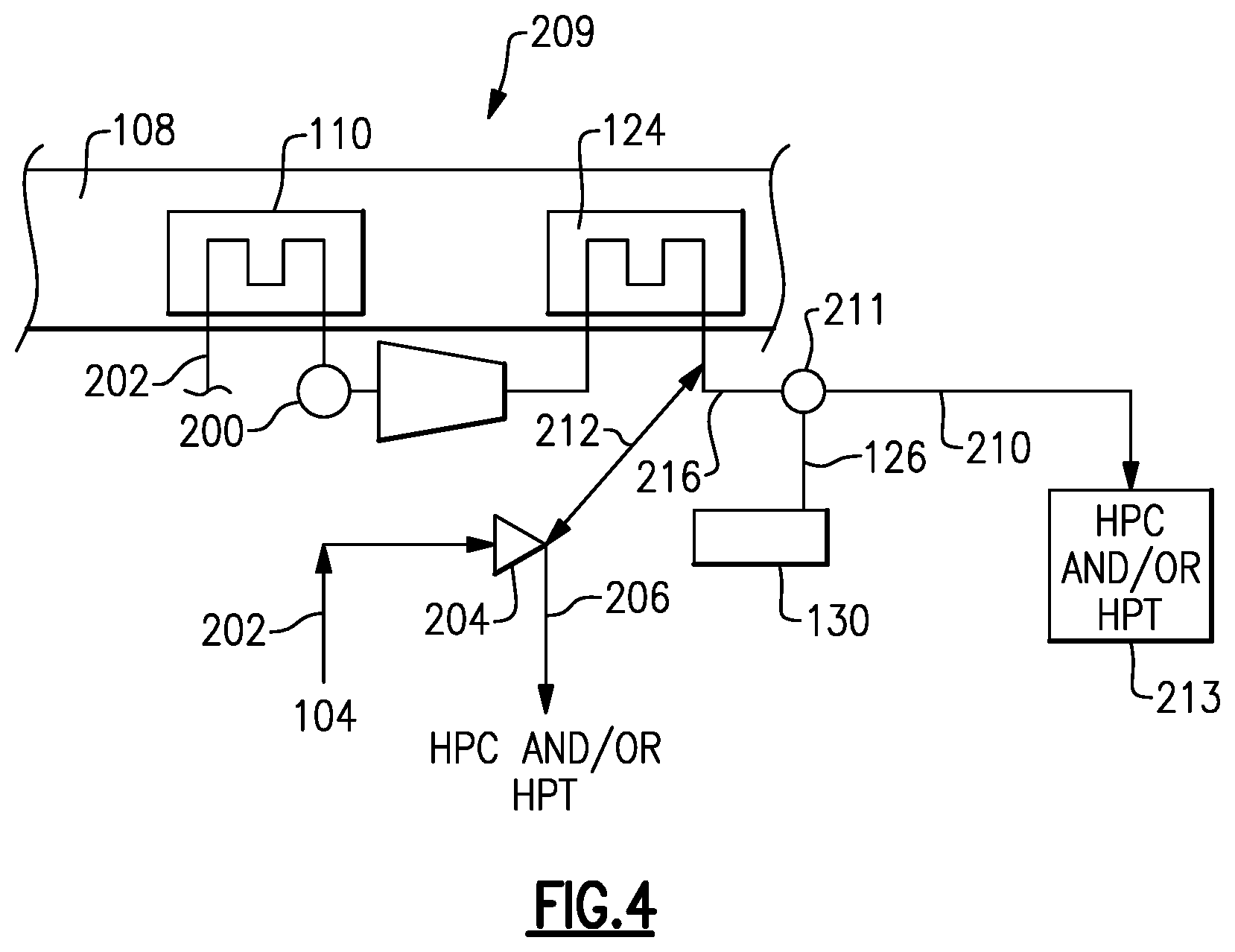
FIG. 4 shows a third embodiment schematic system.
DETAILED DESCRIPTION
FIG. 1 schematically illustrates a gas turbine engine 20. The gas turbine engine 20 is disclosed herein as a two-spool turbofan that generally incorporates a fan section 22, a compressor section 24, a combustor section 26 and a turbine section 28. The fan section 22 drives air along a bypass flow path B in a bypass duct defined within a nacelle 15, and also drives air along a core flow path C for compression and communication into the combustor section 26 then expansion through the turbine section 28. Although depicted as a two-spool turbofan gas turbine engine in the disclosed non-limiting embodiment, it should be understood that the concepts described herein are not limited to use with two-spool turbofans as the teachings may be applied to other types of turbine engines including three-spool architectures.
The exemplary engine 20 generally includes a low speed spool 30 and a high speed spool 32 mounted for rotation about an engine central longitudinal axis A relative to an engine static structure 36 via several bearing systems 38. It should be understood that various bearing systems 38 at various locations may alternatively or additionally be provided, and the location of bearing systems 38 may be varied as appropriate to the application.
The low speed spool 30 generally includes an inner shaft 40 that interconnects, a first (or low) pressure compressor 44 and a first (or low) pressure turbine 46. The inner shaft 40 is connected to the fan 42 through a speed change mechanism, which in exemplary gas turbine engine 20 is illustrated as a geared architecture 48 to drive a fan 42 at a lower speed than the low speed spool 30. The high speed spool 32 includes an outer shaft 50 that interconnects a second (or high) pressure compressor 52 and a second (or high) pressure turbine 54. A combustor 56 is arranged in exemplary gas turbine 20 between the high pressure compressor 52 and the high pressure turbine 54. A mid-turbine frame 57 of the engine static structure 36 may be arranged generally between the high pressure turbine 54 and the low pressure turbine 46. The mid-turbine frame 57 further supports bearing systems 38 in the turbine section 28. The inner shaft 40 and the outer shaft 50 are concentric and rotate via bearing systems 38 about the engine central longitudinal axis A which is collinear with their longitudinal axes.
The core airflow is compressed by the low pressure compressor 44 then the high pressure compressor 52, mixed and burned with fuel in the combustor 56, then expanded over the high pressure turbine 54 and low pressure turbine 46. The mid-turbine frame 57 includes airfoils 59 which are in the core airflow path C. The turbines 46, 54 rotationally drive the respective low speed spool 30 and high speed spool 32 in response to the expansion. It will be appreciated that each of the positions of the fan section 22, compressor section 24, combustor section 26, turbine section 28, and fan drive gear system 48 may be varied. For example, gear system 48 may be located aft of the low pressure compressor, or aft of the combustor section 26 or even aft of turbine section 28, and fan 42 may be positioned forward or aft of the location of gear system 48.
The engine 20 in one example is a high-bypass geared aircraft engine. In a further example, the engine 20 bypass ratio is greater than about six (6), with an example embodiment being greater than about ten (10), the geared architecture 48 is an epicyclic gear train, such as a planetary gear system or other gear system, with a gear reduction ratio of greater than about 2.3 and the low pressure turbine 46 has a pressure ratio that is greater than about five. In one disclosed embodiment, the engine 20 bypass ratio is greater than about ten (10:1), the fan diameter is significantly larger than that of the low pressure compressor 44, and the low pressure turbine 46 has a pressure ratio that is greater than about five 5:1. Low pressure turbine 46 pressure ratio is pressure measured prior to inlet of low pressure turbine 46 as related to the pressure at the outlet of the low pressure turbine 46 prior to an exhaust nozzle. The geared architecture 48 may be an epicycle gear train, such as a planetary gear system or other gear system, with a gear reduction ratio of greater than about 2.3:1 and less than about 5:1. It should be understood, however, that the above parameters are only exemplary of one embodiment of a geared architecture engine and that the present invention is applicable to other gas turbine engines including direct drive turbofans.
A significant amount of thrust is provided by the bypass flow B due to the high bypass ratio. The fan section 22 of the engine 20 is designed for a particular flight condition--typically cruise at about 0.8 Mach and about 35,000 feet (10,668 meters). The flight condition of 0.8 Mach and 35,000 ft (10,668 meters), with the engine at its best fuel consumption--also known as "bucket cruise Thrust Specific Fuel Consumption (`TSFC`)"--is the industry standard parameter of lbm of fuel being burned divided by lbf of thrust the engine produces at that minimum point. "Low fan pressure ratio" is the pressure ratio across the fan blade alone, without a Fan Exit Guide Vane ("FEGV") system. The low fan pressure ratio as disclosed herein according to one non-limiting embodiment is less than about 1.45. "Low corrected fan tip speed" is the actual fan tip speed in ft/sec divided by an industry standard temperature correction of [(Tram .degree.R)/(518.7 .degree.R)].sup.0.5. The "Low corrected fan tip speed" as disclosed herein according to one non-limiting embodiment is less than about 1150 ft/second (350.5 meters/second).
FIG. 2 shows a first schematic system 100 for providing cooling air to various components in a gas turbine engine. As shown, a compressor section 102 has a most downstream location 104. This location is where the air is the most highly compressed in the compressor section 102. A tap location 106 is tapped from a point in the main compressor section which is upstream from the downstream most location 104.
The bypass duct 108, which may be similar to the bypass duct in FIG. 1, is shown receiving a heat exchanger 110. The heat exchanger 110 can be placed in other locations within an engine and the bypass duct is simply an example. Air in the bypass duct will cool the tapped air from tap 106 as it passes through the heat exchanger 110.
The heat exchanger 110 is connected to a cooling compressor 112 which may be driven by a motor, or other drive, to compress the air from the tap 106. Air downstream of the cooling compressor 112 passes to a junction 128. Air downstream of a junction 128 may pass through a passage 114 where it may pass into both, or either, directions 116 and 118. Cooling air passing in a direction 116 may cool the disk or other portions of a rotating components in the compressor and, in particular, the most downstream compressor rotor disk and hub. Air passing in the direction 118 may cool rotating components in a turbine section 122 and, in particular, the most upstream or first turbine blade row and first turbine vane row. As illustrated, a combustor 120 is intermediate the compressor 102 and the turbine 122.
Air also passes into connection 125 from junction 128 and through a second heat exchanger 124. Air at passage 126 is downstream of the heat exchanger 124. This air has been cooled to temperatures far below that found at the junction 128. The air being utilized as cooling air in directions 116 and 118 is important, however, the temperature challenges that it will face in cooling the rotating components is not extreme as the temperature challenges faced by the cooling air in passage 126. Air in passage 126 passes to cool a bearing compartment 130. Bearing compartment 130 is shown supporting a shaft portion 131, which may be a portion of the high pressure spool of an engine such as shown in FIG. 1.
As shown, the bearing compartment 130 is radially inward of the combustor 120. It is desirable that the cooling air in passage 126 is able to maintain the bearing compartment 130 at temperatures below say 800.degree. F., and even say 400.degree. F. (at sea level take off) and even lower. As can be appreciated, putting a bearing compartment 130 radially inward of the combustor section 120 places severe cooling challenges on the bearing compartment 130.
However, the location is particularly advantageous for supporting the high pressure spool shaft portion 131. As an example, the location allows a reduction in the high pressure spool clearance from engine bending due to thrust loads imparted onto engine casings and reduces the chance of local rubout of the high compressor due to the bowed rotor deflection that occurs during starting, and, in general, improves high pressure spool clearances in general from maneuver loads. It should be understood the cooling air from passage 126 also provides buffering to send the bearing compartment 130.
FIG. 3 shows an alternative embodiment 199, wherein a number of the components are similar to embodiment 100. Line 206 generally replaces the line 114 and supplies air to the directions 116 and 118. However, a clutch 200 is shown which allows selective stopping of the cooling compressor 112, such as through a control 201. While a clutch 200 is shown, it should be understood that the control 201 may simply stop operation of the cooling compressor 112. In this embodiment, the cooling compressor 112 can be designed to pressurize the air from tap 106 such that it is even higher than the pressure found at the downstream most location 104.
In this embodiment, a second tap 202 is shown at location 104, and communicating to the line 206 through a check valve 204. It should be understood that the tap 202 can be at any location downstream of the tap 106, and could even be downstream of the point 104. As an example, a location radially outwardly of the combustor 120 would typically be at a pressure generally equivalent to that downstream of the downstream most location 104.
Cooling compressor 112 pressurizes air to a pressure above that found at point 104 while operational. Thus, while the cooling compressor 112 is operating, the check valve 204 will be maintained closed. However, when the control 201 stops compression of air at the cooling compressor 112, the air from the tap 202 will pass through the check valve 204 to line 206, and this air will be supplied to the locations 116 and 118. Air will also be supplied as shown in the first embodiment to the bearing compartment 130.
FIG. 4 shows another embodiment 209. Embodiment 209 generally includes the features shown in FIG. 3 and operates much like FIG. 3. However, there is also a tap 210 downstream of a junction 211, such that air approaching the passage 126 also passes into the line 210 to be delivered to a component 213. The air at tap 210 may cool a number of components 213, such as downstream turbine rotors, other bearing compartments, or any number of other applications. Here, a connector 212 alternatively connects passage 206 to a line 216 leading to the junction 211, or to the passage 206, or both. When the compressor 112 is operational, air will flow downstream of the heat exchanger 124 through the passage 212, into the line 206, as well as toward the junction 211. However, when the cooling compressor 112 is stopped, the air may flow from the tap 202 both to the passage 206, but also through the passage 216 to the junction 211 for the cooling purposes as described above.
The use of the control 201 to stop operation of the cooling compressor 112 increases the efficiency of the engine. As an example, at high power operation, the cooling compressor 112 may be utilized such that the air supply to the rotating components is at a very high pressure. On the other hand, at lower power operation, such as ground idle or cruise the cooling compressor may be stopped to increase the energy efficiency of the engine.
A gas turbine engine under this disclosure could be said to include a plurality of rotatable components housed within a main compressor section and a turbine section. A cooling system is connected to tap air from the main compressor section. A tap is connected to a first heat exchanger. There is a means for raising a pressure of the tapped air downstream of the first heat exchanger. A second heat exchanger is downstream of the cooling compressor. There is a connection downstream of the second heat exchanger. There is also means for delivering air to a bearing compartment. A connection intermediate the cooling compressor and the second heat exchanger delivers cooling air to at least one of the rotatable components.
Although an embodiment of this invention has been disclosed, a worker of ordinary skill in this art would recognize that certain modifications would come within the scope of this disclosure. For that reason, the following claims should be studied to determine the true scope and content of this disclosure.
* * * * *
D00000
D00001
D00002
D00003
XML
uspto.report is an independent third-party trademark research tool that is not affiliated, endorsed, or sponsored by the United States Patent and Trademark Office (USPTO) or any other governmental organization. The information provided by uspto.report is based on publicly available data at the time of writing and is intended for informational purposes only.
While we strive to provide accurate and up-to-date information, we do not guarantee the accuracy, completeness, reliability, or suitability of the information displayed on this site. The use of this site is at your own risk. Any reliance you place on such information is therefore strictly at your own risk.
All official trademark data, including owner information, should be verified by visiting the official USPTO website at www.uspto.gov. This site is not intended to replace professional legal advice and should not be used as a substitute for consulting with a legal professional who is knowledgeable about trademark law.