Drilling oscillation systems and optimized shock tools for same
Donald , et al.
U.S. patent number 10,718,168 [Application Number 15/847,840] was granted by the patent office on 2020-07-21 for drilling oscillation systems and optimized shock tools for same. This patent grant is currently assigned to NATIONAL OILWELL VARCO, L.P.. The grantee listed for this patent is National Oilwell Varco, L.P.. Invention is credited to Sean Matthew Donald, Andrew Lawrence Scott, Yong Yang.


View All Diagrams
| United States Patent | 10,718,168 |
| Donald , et al. | July 21, 2020 |
Drilling oscillation systems and optimized shock tools for same
Abstract
A shock tool for reciprocating a drillstring includes an outer housing and a mandrel assembly coaxially disposed in the outer housing. The outer housing has a radially inner surface including a plurality of circumferentially-spaced splines. The mandrel assembly includes a mandrel having a radially outer surface including a plurality of circumferentially-spaced splines and a plurality of circumferentially-spaced troughs. Each spline of the outer housing is disposed in one trough of the mandrel. Each spline of the mandrel includes a top surface, a first lateral side surface extending radially from the top surface, a second lateral side surface oriented parallel to the first lateral side surface, and a bevel extending from the top surface to the second lateral side surface. Each spline of the mandrel also includes a pocket in the second lateral side surface extending radially from a bottom surface of a trough to the bevel.
| Inventors: | Donald; Sean Matthew (Spring, TX), Scott; Andrew Lawrence (Houston, TX), Yang; Yong (Spring, TX) | ||||||||||
|---|---|---|---|---|---|---|---|---|---|---|---|
| Applicant: |
|
||||||||||
| Assignee: | NATIONAL OILWELL VARCO, L.P.
(Houston, TX) |
||||||||||
| Family ID: | 60972449 | ||||||||||
| Appl. No.: | 15/847,840 | ||||||||||
| Filed: | December 19, 2017 |
Prior Publication Data
| Document Identifier | Publication Date | |
|---|---|---|
| US 20180171726 A1 | Jun 21, 2018 | |
Related U.S. Patent Documents
| Application Number | Filing Date | Patent Number | Issue Date | ||
|---|---|---|---|---|---|
| 62436952 | Dec 20, 2016 | ||||
| Current U.S. Class: | 1/1 |
| Current CPC Class: | E21B 7/24 (20130101); E21B 17/07 (20130101) |
| Current International Class: | E21B 17/07 (20060101); E21B 7/24 (20060101) |
References Cited [Referenced By]
U.S. Patent Documents
| 2991635 | July 1961 | Warren |
| 3949150 | April 1976 | Mason |
| 4186569 | February 1980 | Aumann |
| 4211290 | July 1980 | Mason |
| 2015/0034387 | February 2015 | Malcolm et al. |
| 2147063 | Oct 1996 | CA | |||
| 2874639 | Jun 2015 | CA | |||
| 2008/092256 | Aug 2008 | WO | |||
Other References
|
PCT/US2017/067441 International Search Report and Written Opinion dated May 3, 2018 (16 p.). cited by applicant . PCT/US2017/067441 Written Opinion of the International Preliminary Examining Authority dated Nov. 8, 2018 (8 p.). cited by applicant. |
Primary Examiner: Wright; Giovanna
Attorney, Agent or Firm: Conley Rose, P.C.
Parent Case Text
CROSS-REFERENCE TO RELATED APPLICATIONS
This application claims benefit of U.S. provisional patent application Ser. No. 62/436,952 filed Dec. 20, 2016, and entitled "Optimized Shock Tool for Pressure Pulse (Agitation) Applications," which is hereby incorporated herein by reference in its entirety.
Claims
What is claimed is:
1. A shock tool for reciprocating a drillstring, the shock tool comprising: an outer housing having a central axis, a first end, a second end opposite the first end, and a radially inner surface defining a passage extending axially from the first end to the second end, wherein the radially inner surface of the outer housing includes a plurality of circumferentially-spaced splines; a mandrel assembly coaxially disposed in the passage of the outer housing and configured to move axially relative to the outer housing, wherein the mandrel assembly has a first end axially spaced from the outer housing, a second end disposed in the outer housing, and a passage extending axially from the first end of the mandrel assembly to the second end of the mandrel assembly, wherein the mandrel assembly includes a mandrel having a radially outer surface including a plurality of circumferentially-spaced splines and a plurality of circumferentially-spaced troughs, wherein each trough is circumferentially disposed between a pair of circumferentially adjacent splines of the plurality of splines, wherein each spline of the outer housing is disposed in one trough of the mandrel; wherein each spline of the mandrel includes a radially outer top surface, a first lateral side surface extending from the top surface to a bottom surface of a circumferentially adjacent trough, a second lateral side surface extending radially from a circumferentially adjacent trough, and a bevel extending from the top surface to the second lateral side surface; wherein each spline of the mandrel also includes a pocket in the second lateral side surface extending radially from the corresponding bottom surface to the bevel.
2. The shock tool of claim 1, wherein each bevel is oriented at an acute angle relative to the corresponding top surface and the corresponding second lateral side surface.
3. The shock tool of claim 1, further comprising a first flow passage positioned between each spline of the mandrel and the outer housing, wherein each of the first flow passages is defined by the radially inner surface of the outer housing and one of the bevels.
4. The shock tool of claim 1, further comprising a lock ring disposed about the plurality of splines of the mandrel and configured to limit the axial movement of the mandrel assembly relative to the outer housing; wherein each spline of the mandrel has an first end, a second end, and a recess axially positioned between the first end and the second end of the spline, wherein each recess extends radially inward from the top surface of the corresponding spline of the mandrel, and wherein the lock ring is seated in the recess of each spline; wherein each pocket is axially adjacent the recess of the corresponding spline and is axially positioned between the recess of the corresponding spline and the first end of the corresponding spline.
5. The shock tool of claim 4, further comprising a passage radially positioned between the lock ring and the radially outer surface of the mandrel.
6. The shock tool of claim 1, further comprising a biasing member disposed about the mandrel, wherein the biasing member is disposed in a first annulus radially positioned between the mandrel assembly and the outer housing, wherein the biasing member is configured to generate an axial biasing force that resists axial movement of the mandrel assembly relative to the outer housing; wherein the first annulus is axially adjacent the plurality of splines of the mandrel; an annular flow path radially positioned between the biasing member and the mandrel, wherein the annular flow path extends axially from a first end of the biasing member to a second end of the biasing member.
7. The shock tool of claim 6, further comprising an annular floating piston moveably disposed about a washpipe of the mandrel assembly, wherein the annular floating piston is disposed in a second annulus radially positioned between the mandrel assembly and the outer housing, and wherein the annular floating piston is configured to move axially relative to the mandrel assembly and the outer housing; wherein the washpipe has an first end fixably coupled to the mandrel and a second end distal the mandrel; wherein the washpipe has a radially outer surface extending axially from the first end of the washpipe to the second end of the washpipe; wherein the radially outer surface of the washpipe includes a first cylindrical surface extending axially from the first end of the washpipe and a second cylindrical surface axially positioned between the first cylindrical surface of the washpipe and the second end of the washpipe, wherein the annular floating piston slidably engages the second cylindrical surface; wherein the first cylindrical surface of the washpipe slidingly engages the radially inner surface of the outer housing; wherein the outer surface of the washpipe includes a plurality of circumferentially-spaced recesses in the first cylindrical surface, wherein each recess extends from the first end of the washpipe.
8. The shock tool of claim 7, wherein the washpipe includes a plurality of circumferentially-spaced slots extending axially from the first end of the washpipe, wherein each slot extends radially from the radially outer surface of the washpipe to a radially inner surface of the washpipe, and wherein each slot is disposed in one of the recesses.
9. The shock tool of claim 7, wherein the second annulus is axially positioned between the first annulus and the second end of the mandrel assembly.
10. The shock tool of claim 7, further comprising: an annular seal assembly radially positioned between the outer housing and the mandrel assembly proximal the first end of the outer housing; a hydraulic oil chamber radially positioned between the mandrel assembly and the outer housing, wherein the hydraulic oil chamber extends axially from the annular seal assembly to the annular floating piston.
11. A shock tool for reciprocating a drillstring, the shock tool comprising: an outer housing having a central axis, an upper end, a lower end, and a passage extending axially from the upper end to the lower end; a mandrel assembly disposed in the passage of the outer housing and extending telescopically from the upper end of the outer housing, wherein the mandrel assembly is configured to move axially relative to the outer housing to axially extend and contract the shock tool; a biasing member disposed about the mandrel assembly in a first annulus radially positioned between the mandrel assembly and the outer housing, wherein the biasing member is configured to generate an axial biasing force that resists axial movement of the mandrel assembly relative to the outer housing, and wherein the biasing member slidably engages the outer housing and is radially spaced from the mandrel assembly; and an annular flow passage radially positioned between the biasing member and the mandrel assembly, wherein the annular flow passage extends axially from an upper end of the biasing member to a lower end of the biasing member.
12. The shock tool of claim 11, wherein the biasing member comprises a stack of Belleville springs, wherein the stack of Belleville springs has an inner diameter greater than an outer diameter of a portion of the mandrel assembly about which the biasing member is disposed and an outer diameter that is substantially the same as an inner diameter of a portion of the outer housing within which the biasing member is disposed.
13. The shock tool of claim 11, further comprising an annular floating piston moveably disposed about the mandrel assembly, wherein the annular floating piston is disposed in a second annulus radially positioned between the mandrel assembly and the outer housing, and wherein the annular floating piston is configured to move axially relative to the mandrel assembly and the outer housing.
14. The shock tool of claim 13, wherein the mandrel assembly comprises a mandrel and a washpipe; wherein the washpipe has an upper end fixably coupled to the mandrel, a lower end distal the mandrel, a radially outer surface extending axially from the upper end of the washpipe to the lower end of the washpipe, and a radially inner surface extending axially from the upper end of the washpipe to the lower end of the washpipe; wherein the radially outer surface of the washpipe includes a first cylindrical surface extending axially from the upper end of the washpipe and a second cylindrical surface axially positioned between the first cylindrical surface of the washpipe and the lower end of the washpipe, wherein the annular floating piston slidably engages the second cylindrical surface; wherein the outer surface of the washpipe includes a plurality of circumferentially-spaced recesses in the first cylindrical surface, wherein each recess extends from the first end of the washpipe.
15. The shock tool of claim 14, wherein the washpipe includes a plurality of circumferentially-spaced slots extending axially from the upper end of the washpipe, wherein each slot extends radially from the radially outer surface of the washpipe to a radially inner surface of the washpipe, and wherein each slot is disposed in one of the recesses; wherein the annular flow path is in direct fluid communication with the slots of the washpipe.
16. The shock tool of claim 14, further comprising: an annular seal assembly radially positioned between the outer housing and the mandrel assembly proximal the upper end of the outer housing; a hydraulic oil chamber radially positioned between the mandrel assembly and the outer housing, wherein the hydraulic oil chamber extends axially from the annular seal assembly to the annular floating piston.
17. The shock tool of claim 16, further comprising: a catch coupled to the lower end of the washpipe and defining the lower end of the mandrel assembly; a third annulus radially positioned between the catch and the outer housing; wherein the annular floating piston divides the second annulus into an upper section extending axially from the annular floating piston toward the upper end of the washpipe and a lower section extending axially from the annular floating piston toward the lower end of the mandrel assembly; wherein the third annulus and the lower section of the second annulus are in fluid communication.
18. The shock tool of claim 11, wherein a radially inner surface of the outer housing includes a plurality of circumferentially-spaced splines; wherein a radially outer surface of the mandrel assembly includes a plurality of circumferentially-spaced splines and a plurality of circumferentially-spaced troughs, wherein one trough is circumferentially disposed between each pair of circumferentially adjacent splines of the mandrel assembly, wherein each spline of the outer housing is disposed in one trough of the mandrel assembly; wherein each spline of the mandrel assembly has an upper end, a lower end, a recess axially positioned between the upper end and the lower end, an upper portion extending axially from the recess to the upper end, and a lower portion extending axially from the recess to the lower end, wherein the upper portion of each spline of the mandrel assembly has a cross-sectional geometry that is different from a cross-sectional geometry of the lower portion of the spline.
19. The shock tool of claim 18, wherein the cross-sectional geometry of the upper portion of each spline is trapezoidal and the cross-sectional geometry of the lower portion of each spline is rectangular.
20. The shock tool of claim 18, wherein the upper portion of each spline of the mandrel assembly includes a pocket extending radially outward along a lateral side of the spline to a flow passage extending axially between the spline of the mandrel and the radially inner surface of the outer housing.
Description
STATEMENT REGARDING FEDERALLY SPONSORED RESEARCH OR DEVELOPMENT
Not applicable.
BACKGROUND
The disclosure relates generally to downhole tools. More particularly, the disclosure relates to downhole oscillation systems for inducing axial oscillations in drill strings during drilling operations. Still more particularly, the disclosure relates to shock tools that directly and efficiently convert cyclical pressure pulses in drilling fluid into axial oscillations.
Drilling operations are performed to locate and recover hydrocarbons from subterranean reservoirs. Typically, an earth-boring drill bit is typically mounted on the lower end of a drill string and is rotated by rotating the drill string at the surface or by actuation of downhole motors or turbines, or by both methods. With weight applied to the drill string, the rotating drill bit engages the earthen formation and proceeds to form a borehole along a predetermined path toward a target zone.
During drilling, the drillstring may rub against the sidewall of the borehole. Frictional engagement of the drillstring and the surrounding formation can reduce the rate of penetration (ROP) of the drill bit, increase the necessary weight-on-bit (WOB), and lead to stick slip. Accordingly, various downhole tools that induce vibration and/or axial reciprocation may be included in the drillstring to reduce friction between the drillstring and the surrounding formation. One such tool is an oscillation system, which typically includes an pressure pulse generator and a shock tool. The pressure pulse generator produces pressure pulses in the drilling fluid flowing therethrough and the shock tool converts the pressure pulses in the drilling fluid into axial reciprocation. The pressure pulses created by the pressure pulse generator are cyclic in nature. The continuous stream of pressure peaks and troughs in the drilling fluid cause the shock tool to cyclically extend and retract telescopically at the pressure peak and pressure trough, respectively. A spring is usually used to induce the axial retraction during the pressure trough.
BRIEF SUMMARY OF THE DISCLOSURE
Embodiments of shock tools for reciprocating drillstrings are disclosed herein. In one embodiment, a shock tool for reciprocating a drillstring comprises an outer housing having a central axis, a first end, a second end opposite the first end, and a radially inner surface defining a passage extending axially from the first end to the second end. The radially inner surface of the outer housing includes a plurality of circumferentially-spaced splines. In addition, the shock tool comprises a mandrel assembly coaxially disposed in the passage of the outer housing and configured to move axially relative to the outer housing. The mandrel assembly has a first end axially spaced from the outer housing, a second end disposed in the outer housing, and a passage extending axially from the first end of the mandrel assembly to the second end of the mandrel assembly. The mandrel assembly includes a mandrel having a radially outer surface including a plurality of circumferentially-spaced splines and a plurality of circumferentially-spaced troughs. Each trough of the mandrel is circumferentially disposed between a pair of circumferentially adjacent splines of the plurality of splines of the mandrel. Each spline of the outer housing is disposed in one trough of the mandrel. Each spline of the mandrel includes a radially outer top surface, a first lateral side surface extending radially from the top surface to a bottom surface of a circumferentially adjacent trough of the mandrel, a second lateral side surface extending radially from a circumferentially adjacent trough of the mandrel, and a bevel extending from the top surface to the second lateral side surface. Each spline of the mandrel also includes a pocket in the second lateral side surface extending radially from the corresponding bottom surface to the bevel.
In another embodiment, a shock tool for reciprocating a drillstring comprises an outer housing having a central axis, an upper end, a lower end, and a passage extending axially from the upper end to the lower end. In addition, the shock tool comprises a mandrel assembly disposed in the passage of the outer housing and extending telescopically from the upper end of the outer housing. The mandrel assembly is configured to move axially relative to the outer housing to axially extend and contract the shock tool. Further, the shock tool comprises a biasing member disposed about the mandrel assembly in a first annulus radially positioned between the mandrel assembly and the outer housing. The biasing member is configured to generate an axial biasing force that resists axial movement of the mandrel assembly relative to the outer housing. The biasing member slidably engages the outer housing and is radially spaced from the mandrel assembly. Still further, the shock tool comprises an annular flow passage radially positioned between the biasing member and the mandrel assembly. The annular flow passage extends axially from an upper end of the biasing member to a lower end of the biasing member.
Embodiments described herein comprise a combination of features and advantages intended to address various shortcomings associated with certain prior devices, systems, and methods. The foregoing has outlined rather broadly the features and technical advantages of the invention in order that the detailed description of the invention that follows may be better understood. The various characteristics described above, as well as other features, will be readily apparent to those skilled in the art upon reading the following detailed description, and by referring to the accompanying drawings. It should be appreciated by those skilled in the art that the conception and the specific embodiments disclosed may be readily utilized as a basis for modifying or designing other structures for carrying out the same purposes of the invention. It should also be realized by those skilled in the art that such equivalent constructions do not depart from the spirit and scope of the invention as set forth in the appended claims.
BRIEF DESCRIPTION OF THE DRAWINGS
For a detailed description of the preferred embodiments of the invention, reference will now be made to the accompanying drawings in which:
FIG. 1 is a schematic view of a drilling system including an embodiment of an oscillation system in accordance with the principles described herein;
FIG. 2 is a side view of the shock tool of the oscillation system of FIG. 1;
FIG. 3 is a cross-sectional side view of the shock tool of FIG. 2;
FIG. 4 is an enlarged cross-sectional side view of the shock tool of FIG. 2 taken in section 4-4 FIG. 3;
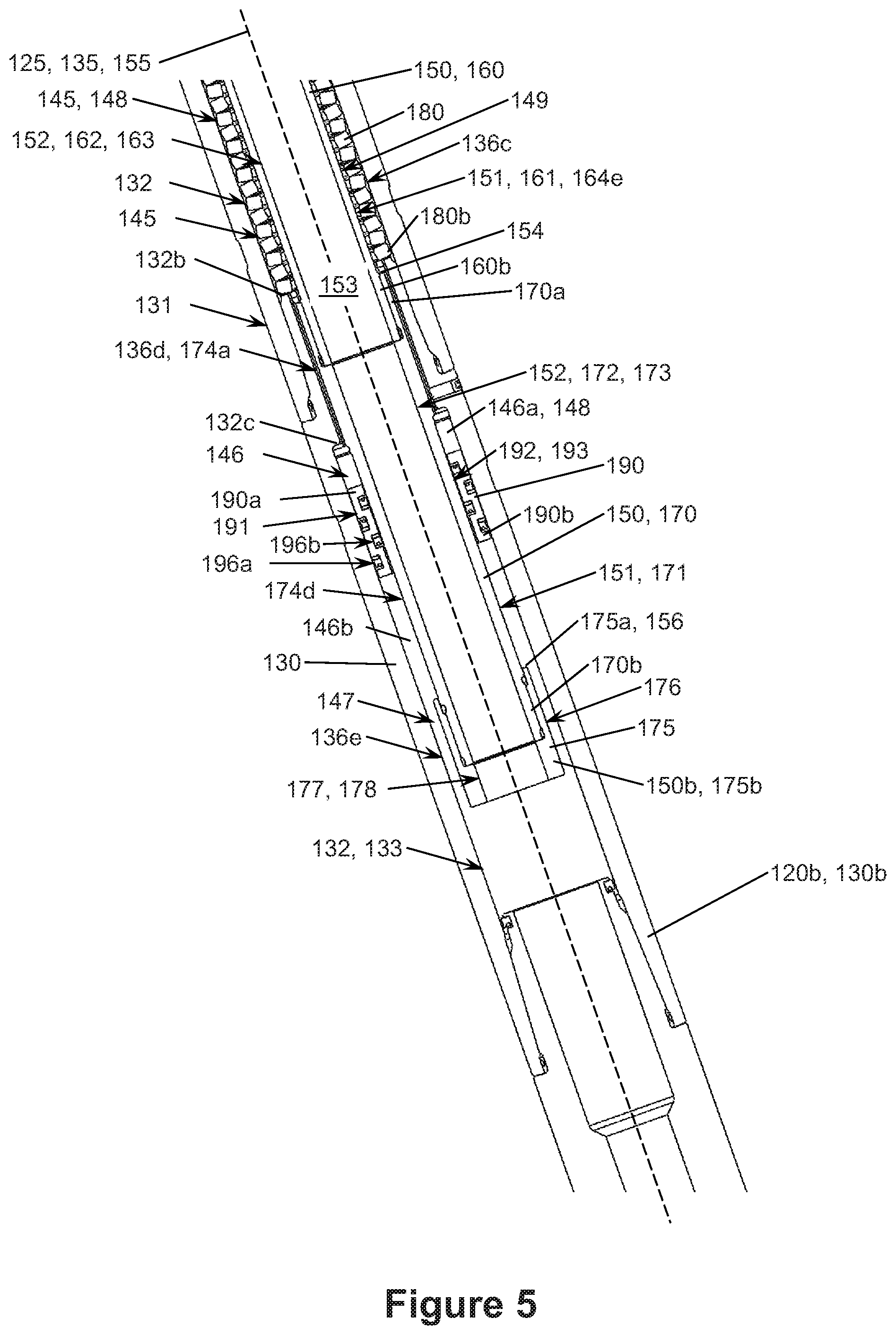
FIG. 5 is an enlarged cross-sectional side view of the shock tool of FIG. 2 taken in section 5-5 of FIG. 3;
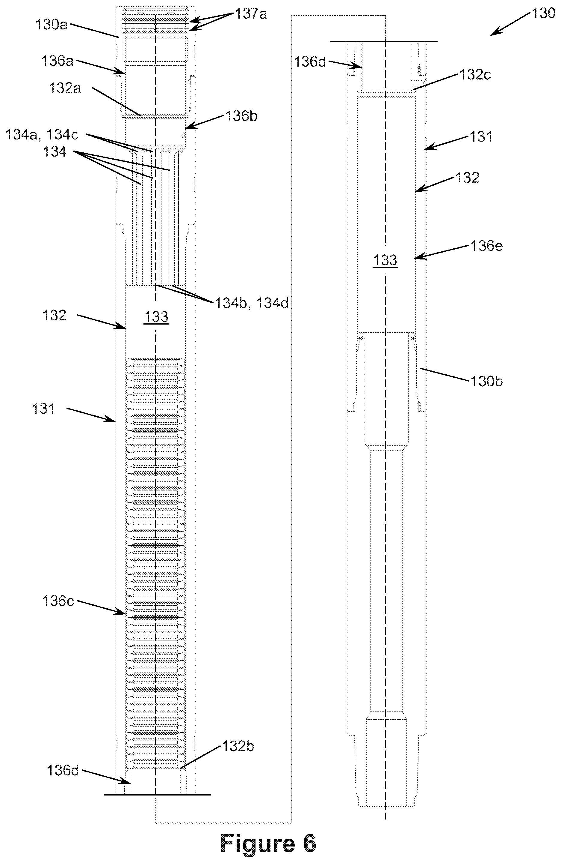
FIG. 6 is a cross-sectional side view of the outer housing and the biasing member of the shock tool of FIG. 3;
FIG. 7 is a side view of the mandrel assembly of the shock tool of FIG. 3;
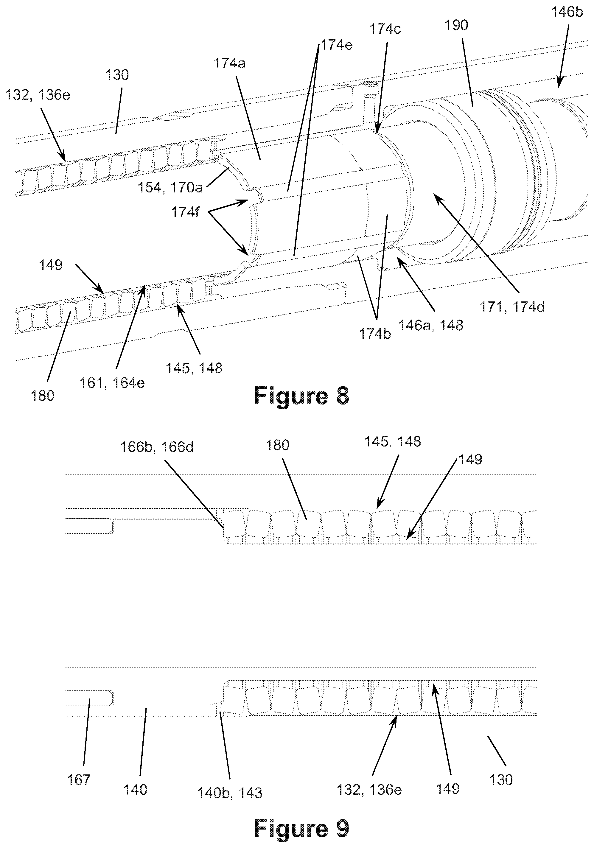
FIG. 8 is a partial cross-sectional perspective view of the shock tool of FIG. 2;
FIG. 9 is a cross-sectional side view of the shock tool of FIG. 2 taken in section 9-9 of FIG. 3;
FIG. 10 is a perspective view of the washpipe of FIG. 7;
FIG. 11 is a side view of the washpipe of FIG. 7;
FIG. 12 is a partial cross-sectional perspective view of the shock tool of FIG. 2;
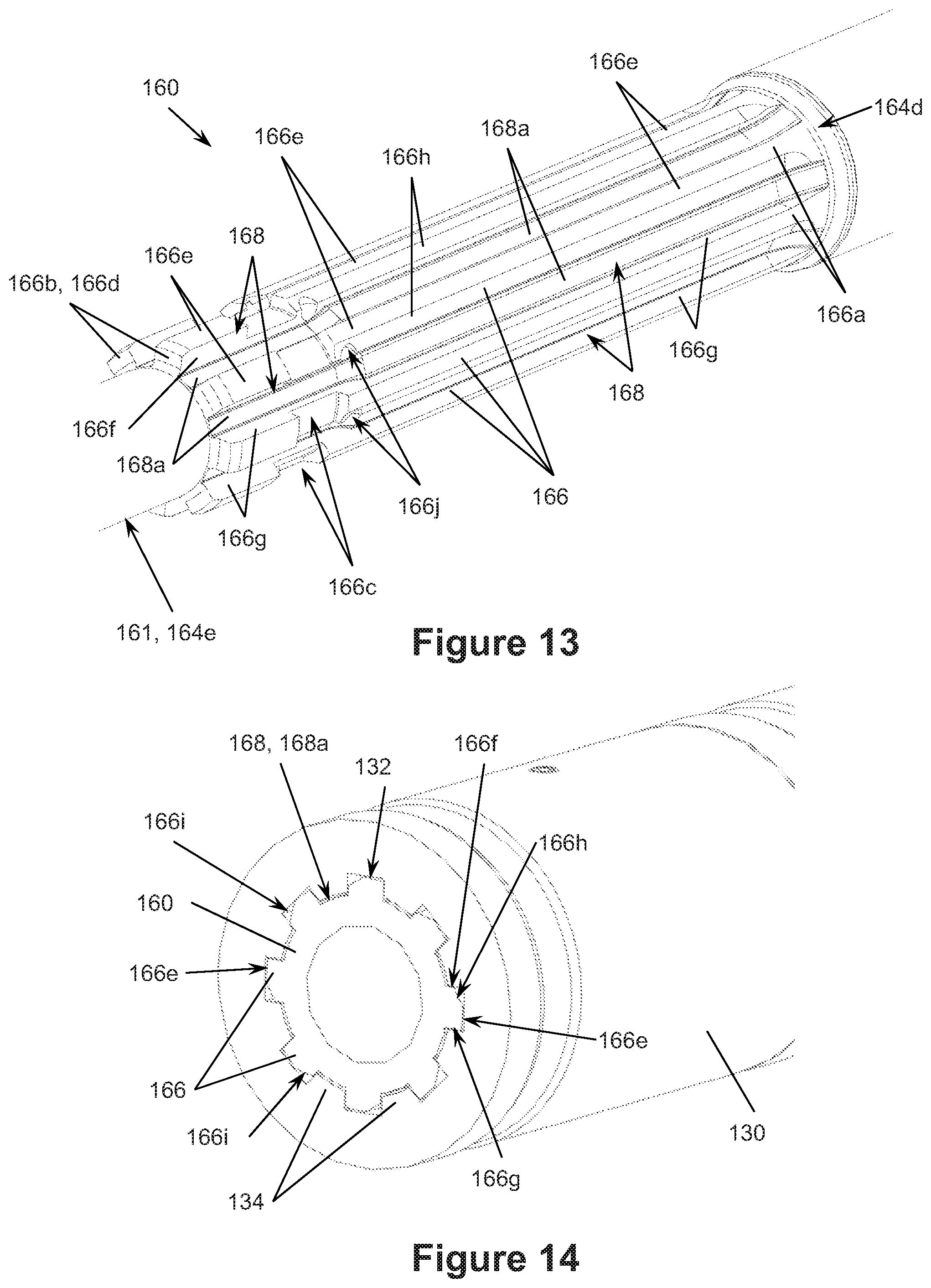
FIG. 13 is an enlarged partial perspective view of the mandrel of FIG. 7; and
FIG. 14 is a cross-sectional perspective view of the shock tool of FIG. 2 illustrating the intermeshing splines of the mandrel and the outer housing.
DETAILED DESCRIPTION OF THE PREFERRED EMBODIMENTS
The following discussion is directed to various exemplary embodiments. However, one skilled in the art will understand that the examples disclosed herein have broad application, and that the discussion of any embodiment is meant only to be exemplary of that embodiment, and not intended to suggest that the scope of the disclosure, including the claims, is limited to that embodiment.
Certain terms are used throughout the following description and claims to refer to particular features or components. As one skilled in the art will appreciate, different persons may refer to the same feature or component by different names. This document does not intend to distinguish between components or features that differ in name but not function. The drawing figures are not necessarily to scale. Certain features and components herein may be shown exaggerated in scale or in somewhat schematic form and some details of conventional elements may not be shown in interest of clarity and conciseness.
In the following discussion and in the claims, the terms "including" and "comprising" are used in an open-ended fashion, and thus should be interpreted to mean "including, but not limited to . . . ." Also, the term "couple" or "couples" is intended to mean either an indirect or direct connection. Thus, if a first device couples to a second device, that connection may be through a direct connection of the two devices, or through an indirect connection that is established via other devices, components, nodes, and connections. In addition, as used herein, the terms "axial" and "axially" generally mean along or parallel to a particular axis (e.g., central axis of a body or a port), while the terms "radial" and "radially" generally mean perpendicular to a particular axis. For instance, an axial distance refers to a distance measured along or parallel to the axis, and a radial distance means a distance measured perpendicular to the axis. Any reference to up or down in the description and the claims is made for purposes of clarity, with "up", "upper", "upwardly", "uphole", or "upstream" meaning toward the surface of the borehole and with "down", "lower", "downwardly", "downhole", or "downstream" meaning toward the terminal end of the borehole, regardless of the borehole orientation. As used herein, the terms "approximately," "about," "substantially," and the like mean within 10% (i.e., plus or minus 10%) of the recited value. Thus, for example, a recited angle of "about 80 degrees" refers to an angle ranging from 72 degrees to 88 degrees.
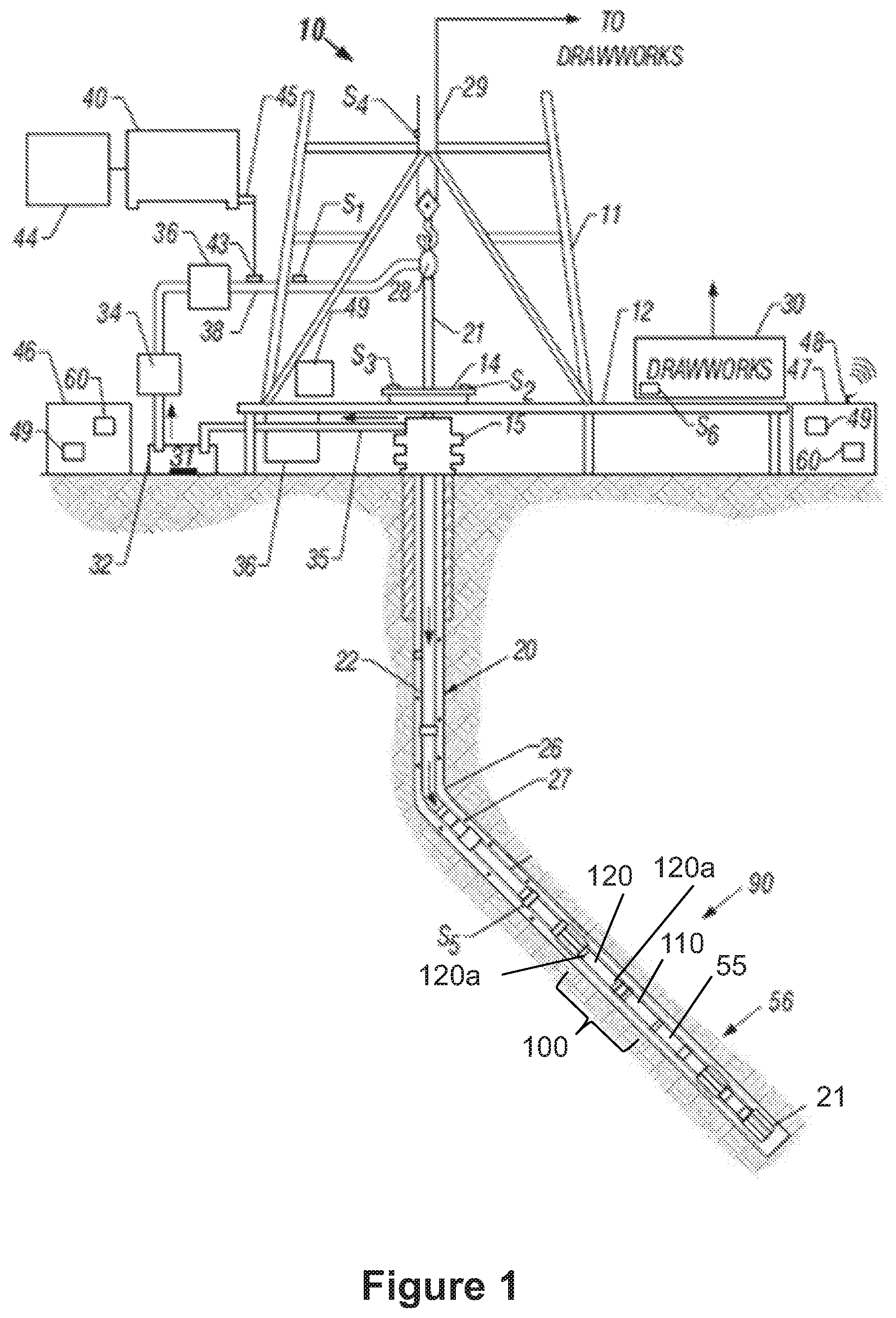
Referring now to FIG. 1, a schematic view of an embodiment of a drilling system 10 is shown. Drilling system 10 includes a derrick 11 having a floor 12 supporting a rotary table 14 and a drilling assembly 90 for drilling a borehole 26 from derrick 11. Rotary table 14 is rotated by a prime mover such as an electric motor (not shown) at a desired rotational speed and controlled by a motor controller (not shown). In other embodiments, the rotary table (e.g., rotary table 14) may be augmented or replaced by a top drive suspended in the derrick (e.g., derrick 11) and connected to the drillstring (e.g., drillstring 20).
Drilling assembly 90 includes a drillstring 20 and a drill bit 21 coupled to the lower end of drillstring 20. Drillstring 20 is made of a plurality of pipe joints 22 connected end-to-end, and extends downward from the rotary table 14 through a pressure control device 15, such as a blowout preventer (BOP), into the borehole 26. Drill bit 21 is rotated with weight-on-bit (WOB) applied to drill the borehole 26 through the earthen formation. Drillstring 20 is coupled to a udrawworks 30 via a kelly joint 21, swivel 28, and line 29 through a pulley. During drilling operations, drawworks 30 is operated to control the WOB, which impacts the rate-of-penetration of drill bit 21 through the formation. In addition, drill bit 21 can be rotated from the surface by drillstring 20 via rotary table 14 and/or a top drive, rotated by downhole mud motor 55 disposed along drillstring 20 proximal bit 21, or combinations thereof (e.g., rotated by both rotary table 14 via drillstring 20 and mud motor 55, rotated by a top drive and the mud motor 55, etc.). For example, rotation via downhole motor 55 may be employed to supplement the rotational power of rotary table 14, if required, and/or to effect changes in the drilling process. In either case, the rate-of-penetration (ROP) of the drill bit 21 into the borehole 26 for a given formation and a drilling assembly largely depends upon the WOB and the rotational speed of bit 21.
During drilling operations a suitable drilling fluid 31 is pumped under pressure from a mud tank 32 through the drillstring 20 by a mud pump 34. Drilling fluid 31 passes from the mud pump 34 into the drillstring 20 via a desurger 36, fluid line 38, and the kelly joint 21. The drilling fluid 31 pumped down drillstring 20 flows through mud motor 55 and is discharged at the borehole bottom through nozzles in face of drill bit 21, circulates to the surface through an annulus 27 radially positioned between drillstring 20 and the sidewall of borehole 26, and then returns to mud tank 32 via a solids control system 36 and a return line 35. Solids control system 36 may include any suitable solids control equipment known in the art including, without limitation, shale shakers, centrifuges, and automated chemical additive systems. Control system 36 may include sensors and automated controls for monitoring and controlling, respectively, various operating parameters such as centrifuge rpm. It should be appreciated that much of the surface equipment for handling the drilling fluid is application specific and may vary on a case-by-case basis.
While drilling, one or more portions of drillstring 20 may contact and slide along the sidewall of borehole 26. To reduce friction between drillstring 20 and the sidewall of borehole 26, in this embodiment, an oscillation system 100 is provided along drillstring 20 proximal motor 55 and bit 21. Oscillation system 100 includes a pressure pulse generator 110 coupled to motor 55 and a shock tool 120 coupled to pulse generator 110. Pulse generator 110 generates cyclical pressure pulses in the drilling fluid flowing down drillstring 20, and shock tool 120 cyclically and axially extends and retracts in response to the pressure pulses as will be described in more detail below. With bit 21 disposed on the hole bottom, the axial extension and retraction of shock tool 120 induces axial reciprocation in the portion of drillstring above oscillation system 100, which reduces friction between drillstring 20 and the sidewall of borehole 26.
In general, pulse generator 110 and mud motor 55 can be any pressure pulse generator and mud motor, respectively, known in the art. For example, as is known in the art, pulse generator 110 can be a valve operated to cyclically open and close as a rotor of mud motor 55 rotates within a stator of mud motor 55. When the valve opens, the pressure of the drilling mud upstream of pulse generator 110 decreases, and when the valve closes, the pressure of the drilling mud upstream of pulse generator 110 increases. Examples of such valves are disclosed in U.S. Pat. Nos. 6,279,670, 6,508,317, 6,439,318, and 6,431,294, each of which is incorporated herein by reference in its entirety for all purposes.
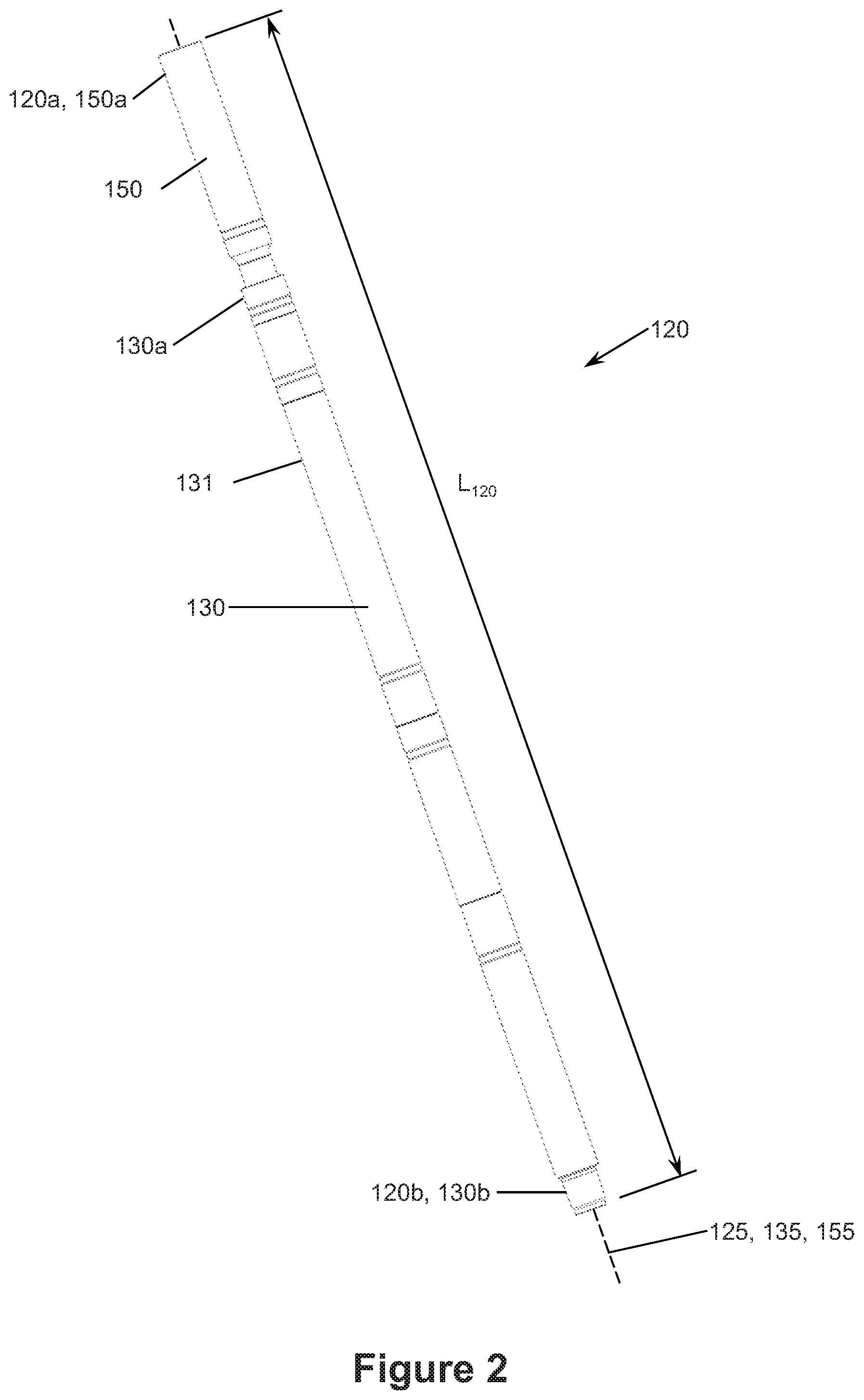
Referring now to FIGS. 2 and 3, shock tool 120 of oscillation system 100 is shown. Shock tool 120 has a first or uphole end 120a, a second or downhole end 120b opposite end 120a, and a central or longitudinal axis 125. As shown in FIG. 1, uphole end 120a is coupled to the portion of drillstring 20 disposed above oscillation system 100 and downhole end 120b is coupled to pulse generator 110. Tool 120 has a length L.sub.120 measured axially from upper end 120a to lower end 120b. As will be described in more detail below, shock tool 120 cyclically axially extends and retracts in response to the pressure pulses in the drilling fluid generated by pulse generator 110 during drilling operations. During extension of tool 120, ends 120a, 120b move axially away from each other and length L.sub.120 increases, and during contraction of tool 120, ends 120a, 120b move axially toward each other and length L.sub.120 decreases. Thus, shock tool 120 may be described as having an "extended" position with ends 120a, 120b axially spaced apart to the greatest extent (i.e., when length L.sub.120 is at a maximum) and a retracted position with ends 120a, 120b axially spaced apart to the smallest extent (i.e., when length L.sub.120 is at a minimum).
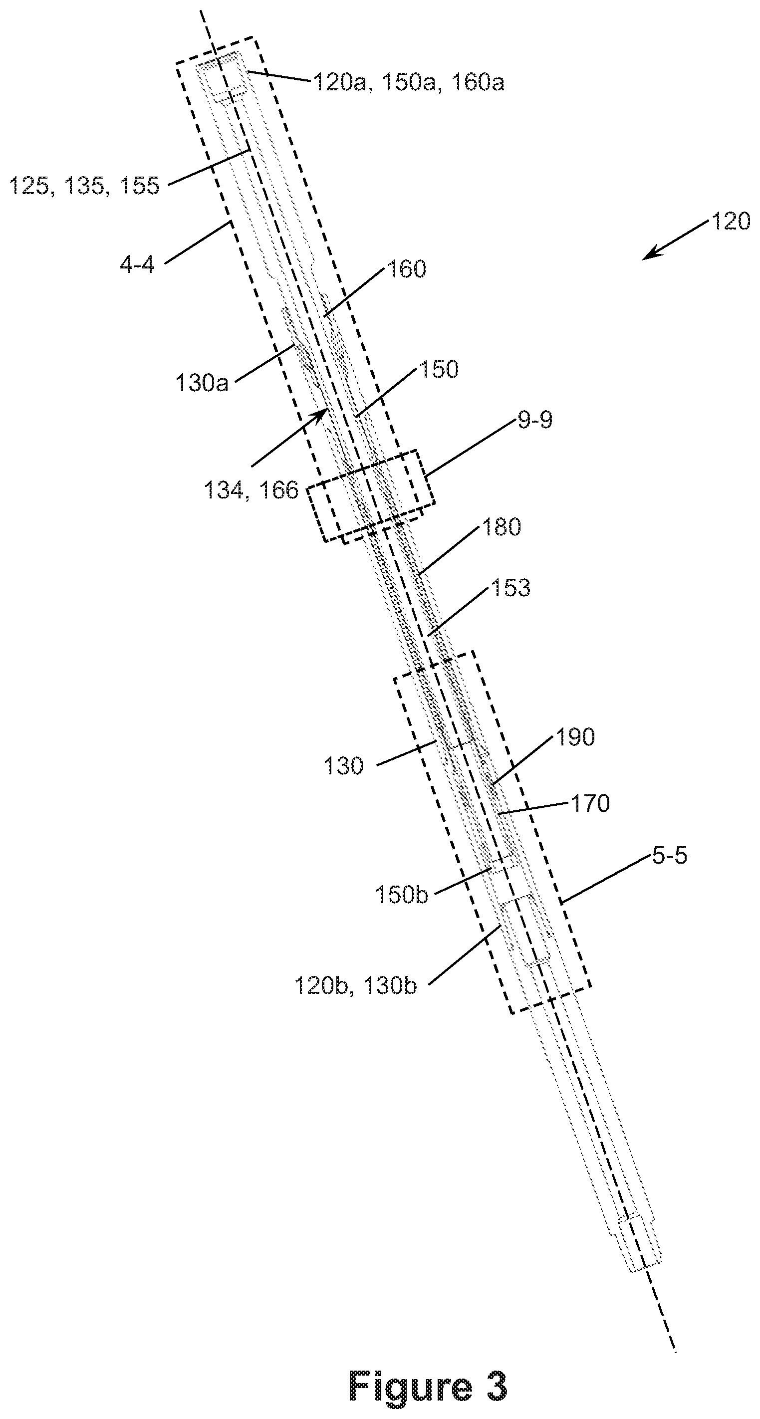
Referring still to FIGS. 2 and 3, in this embodiment, shock tool 120 includes an outer housing 130, a mandrel assembly 150 telescopically disposed within outer housing 130, a biasing member 180 disposed about mandrel assembly 150 within outer housing 130, and an annular floating piston 190 disposed about mandrel assembly 150 within outer housing 130. Thus, biasing member 180 and floating piston 190 are radially positioned between mandrel assembly 150 and outer housing 130. Mandrel assembly 150 and outer housing 130 are tubular members, each having a central or longitudinal axis 155, 135, respectively, coaxially aligned with axis 125 of shock tool 120. Mandrel assembly 150 can move axially relative to outer housing 130 to enable the cyclical axial extension and retraction of shock tool 120. Biasing member 180 axially biases mandrel assembly 150 and shock tool 120 to a "neutral" position between the extended position and the retracted position. As will be described in more detail below, floating piston 190 is free to move axially along mandrel assembly 150 and defines a barrier to isolate biasing member 180 and hydraulic oil from drilling fluids.
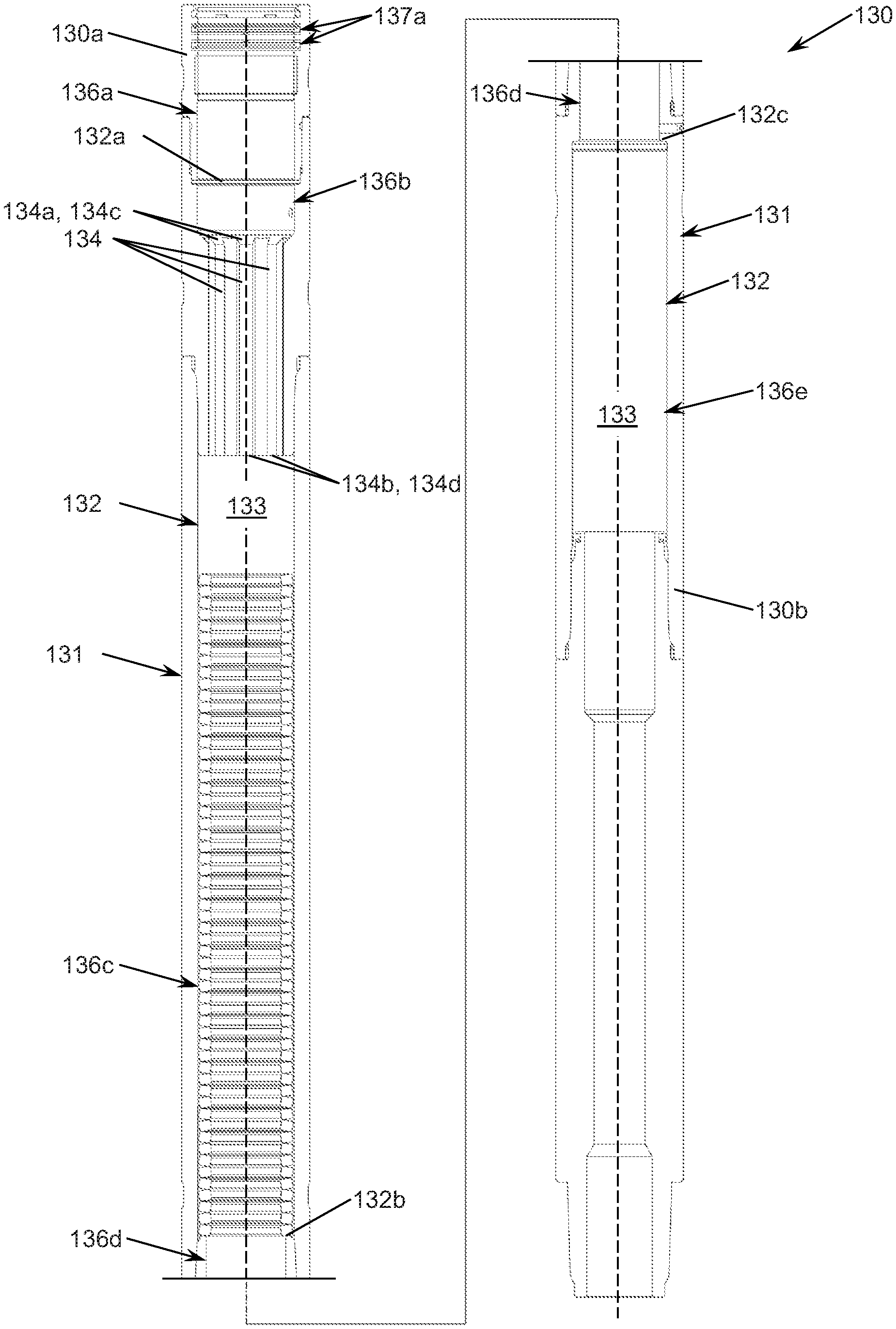
Referring now to FIGS. 4-6, outer housing 130 has a first or uphole end 130a, a second or downhole end 130b opposite end 130a, a radially outer surface 131 extending axially between ends 130a, 130b, and a radially inner surface 132 extending axially between ends 130a, 130b. Uphole end 130a is axially positioned below uphole end 120a of shock tool 120. However, downhole end 130b is coincident with, and hence defines downhole end 120b of shock tool 120.
Inner surface 132 defines a central throughbore or passage 133 extending axially through housing 130 (i.e., from uphole end 130a to downhole end 130b). Outer surface 131 is disposed at a radius that is uniform or constant moving axially between ends 130a, 130b. Thus, outer surface 131 is generally cylindrical between ends 130a, 130b. Inner surface 132 is disposed at a radius that varies moving axially between ends 130a, 130b.
In this embodiment, outer housing 130 is formed with a plurality of tubular members connected end-to-end with mating threaded connections (e.g., box and pin connections). Some of the tubular members forming outer housing 130 define annular shoulders along inner surface 132. In particular, moving axially from uphole end 130a to downhole end 130b, inner surface 132 includes a frustoconical uphole facing annular shoulder 132a, an uphole facing annular shoulder 132b, and a downward facing planar annular shoulder 132c. In addition, inner surface 132 includes a plurality of circumferentially-spaced parallel internal splines 134 axially positioned between shoulders 132a, 132b. As will be described in more detail below, splines 134 slidingly engage mating external splines on mandrel assembly 150, thereby allowing mandrel assembly 150 to move axially relative to outer housing 130 but preventing mandrel assembly 150 from rotating about axis 125 relative to outer housing 130. Each spline 134 extends axially between a first or uphole end 134a and a second or downhole end 134b. The uphole ends 134a of splines 134 define a plurality of circumferentially-spaced uphole facing frustoconical shoulders 134c extending radially into passage 133, and the downhole ends 134b of splines 134 define a plurality of circumferentially-spaced downhole facing planar shoulders 134d extending radially into passage 133.
Referring still to FIGS. 4-6, inner surface 132 also includes a cylindrical surface 136a extending axially from end 130a to shoulder 132a, a cylindrical surface 136b extending axially between shoulders 132a, 134c, a cylindrical surface 136c extending axially between shoulders 134d, 132b, a cylindrical surface 136d extending axially between shoulders 132b, 132c, and a cylindrical surface 136e extending axially between shoulders 132c, 132d.
Along each cylindrical surface 136a, 136b, 136c, 136d, 136e the radius of inner surface 132 is constant and uniform, however, since shoulders 132a, 132b, 132c, 134c, 134d extend radially, the radius of inner surface 132 along different cylindrical surfaces 136a, 136b, 136c, 136d, 136e may vary. As best shown in FIGS. 4-6, and as will be described in more detail below, cylindrical surfaces 136a, 136d slidingly engage mandrel assembly 150, whereas cylindrical surfaces 136b, 136c, 136e are radially spaced from mandrel assembly 150. In this embodiment, a plurality of axially spaced annular seal assemblies 137a are disposed along cylindrical surface 136a and radially positioned between mandrel assembly 150 and outer housing 130. Seal assemblies 137a form annular seals between mandrel assembly 150 and outer housing 130, thereby preventing fluids from flowing axially between cylindrical surface 136a and mandrel assembly 150. Thus, seal assemblies 137a prevent fluids from inside housing 130 from flowing upwardly between mandrel assembly 150 and end 130a into annulus 27 during drilling operations, and prevent fluids in annulus 27 from flowing between mandrel assembly 150 and end 130a into housing 130.
Referring now to FIGS. 4, 5, and 7, mandrel assembly 150 has a first or uphole end 150a, a second or downhole end 150b opposite end 150a, a radially outer surface 151 extending axially between ends 150a, 150b, and a radially inner surface 152 extending axially between ends 150a, 150b. Uphole end 150a is coincident with, and hence defines uphole end 120a of shock tool 120. In addition, uphole end 150a is axially positioned above uphole end 130a of outer housing 130. Downhole end 150b is disposed without outer housing 130 and axially positioned above downhole end 130b. Inner surface 152 defines a central throughbore or passage 153 extending axially through mandrel assembly 150 (i.e., from uphole end 150a to downhole end 150b). Inner surface 152 is disposed at a radius that is uniform or constant moving axially between ends 150a, 150b. Thus, inner surface 152 is generally cylindrical between ends 150a, 150b. Outer surface 151 is disposed at a radius that varies moving axially between ends 150a, 150b. In this embodiment, mandrel assembly 150 includes a mandrel 160 and a tubular member or washpipe 170 coupled to mandrel 160. Mandrel 160 and washpipe 170 are connected end-to-end and are coaxially aligned with axis 155.
Referring still to FIGS. 4, 5, and 7, mandrel 160 has a first or uphole end 160a, a second or downhole end 160b opposite end 160a, a radially outer surface 161 extending axially between ends 160a, 160b, and a radially inner surface 162 extending axially between ends 160a, 160b. Uphole end 160a is coincident with, and hence defines uphole end 150a of mandrel assembly 150. Inner surface 162 is a cylindrical surface defining a central throughbore or passage 163 extending axially through mandrel 160. Inner surface 162 and passage 163 define a portion of inner surface 152 and passage 153, respectively, of mandrel assembly 150.
Moving axially from uphole end 160a, outer surface 161 includes a cylindrical surface 164a, extending from end 160a, a concave downhole facing annular shoulder 164b, a cylindrical surface 164c extending from shoulder 164b, an annular downhole facing annular shoulder 164d, a plurality circumferentially-spaced parallel external splines 166, and a cylindrical surface 164e axially positioned between splines 166 and downhole end 160b. A portion of outer surface 161 extending from downhole end 160b includes external threads that threadably engage mating internal threads of washpipe 170.
As best shown in FIG. 7, splines 166 are axially positioned between shoulder 164d and cylindrical surface 164e. Each spline 166 extends axially between a first or uphole end 166a proximal shoulder 164d and a second or downhole end 166b distal shoulder 164d. In this embodiment, each spline 166 includes a recess 166c positioned proximal downhole end 166b. Recesses 166c are disposed at the same axial position along splines 166 and circumferentially aligned. A lock ring 167 is dispose about splines 166 (and mandrel 160) and seated in recesses 166c. Lock ring 167 functions as a shouldering mechanism to limit the upward travel of mandrel 160 relative to housing 130. In particular, as best shown in FIG. 4, mandrel 160 can move axially upward relative to housing 130 until lock ring 167 axially engages shoulders 134d at lower ends 134b of splines 134, thereby preventing further axial upward movement of mandrel 160 relative to housing 130. Limiting the upward travel of the mandrel 160 relative to housing 130 reduces the likelihood of overstressing biasing member 180. In this embodiment, the upward travel of mandrel 160 relative to housing 130 is limited to about 1.0 in.
Referring again to FIGS. 4, 5, and 7, the downhole ends 166b of splines 166 define a plurality of circumferentially-spaced downhole facing planar shoulders 166d. Splines 166 of mandrel 160 slidingly engage mating splines 134 of outer housing 130, thereby allowing mandrel assembly 150 to move axially relative to outer housing 130 but preventing mandrel assembly 150 from rotating about axis 125 relative to outer housing 130. Thus, engagement of mating splines 134, 166 enables the transfer of rotation torque between mandrel assembly 150 and outer housing 130 during drilling operations.
Washpipe 170 has a first or uphole end 170a, a second or downhole end 170b opposite end 170a, a radially outer surface 171 extending axially between ends 170a, 170b, and a radially inner surface 172 extending axially between ends 170a, 170b. Inner surface 172 is a cylindrical surface defining a central throughbore or passage 173 extending axially through washpipe 170. Inner surface 172 and passage 173 define a portion of inner surface 152 and passage 153, respectively, of mandrel assembly 150. A portion of inner surface 172 extending axially from uphole end 170a includes internal threads that threadably engage the mating external threads provided at downhole end 160b of mandrel 160, thereby fixably securing mandrel 160 and washpipe 170 end-to-end. With end 160b of mandrel 160 threaded into uphole end 170a of washpipe 170, end 170a defines an annular uphole facing planar shoulder 154 along outer surface 151.
As best shown in FIGS. 5 and 7, moving axially from uphole end 170a toward downhole end 170b, outer surface 171 includes a cylindrical surface 174a extending from end 170a, a plurality of uniformly circumferentially-spaced flats 174b axially adjacent cylindrical surface 174a, a downhole facing planar annular shoulder 174c, and a cylindrical surface 174d extending from shoulder 174c. A portion of outer surface 171 at downhole end 170b includes external threads that threadably engage mating internal threads of an annular catch 175. Catch 175 is disposed about downhole end 170b of washpipe 170 and extends axially therefrom. Catch 175 has a first or uphole end 175a, a second or downhole end 175b opposite end 175a, a radially outer surface 176 extending axially between ends 175a, 175b, and a radially inner surface 177 extending axially between ends 175a, 175b. Inner surface 177 defines a central throughbore or passage 178 extending axially through piston 175. Inner surface 177 and passage 178 define a portion of inner surface 152 and passage 153, respectively, of mandrel assembly 150. A portion of inner surface 177 extending axially from upper end 175a includes internal threads that threadably engage the mating external threads provided at downhole end 170b of washpipe 170, thereby fixably securing catch 175 to downhole end 170b of washpipe 170. With end 170b of washpipe 170 threaded into catch 175, the uphole end 175a of catch 175 defines an annular uphole facing planar shoulder 156 along outer surface 151. In this embodiment, outer surface 176 is radially spaced from inner surface 132 of housing 130 as shown in FIG. 5.
Referring now to FIGS. 4 and 5, mandrel assembly 150 is disposed within outer housing 130 with mating splines 134, 166 intermeshed and slidingly engaging, and uphole ends 150a, 160a positioned above end 130a of housing 130. In addition, cylindrical surfaces 136a, 164c slidingly engage with annular seal assemblies 137a sealingly engaging surface 164c of mandrel 160, and cylindrical surfaces 136d, 174a slidingly engage. Cylindrical surfaces 136d, 174a are radially adjacent one another, however, seals are not provided between surfaces 136d, 174a. Thus, although surfaces 136d, 174a may slidingly engage, fluid can flow therebetween. Cylindrical surface 136c of outer housing 130 is radially opposed to the lower portions of external splines 166 of mandrel 160 but radially spaced therefrom. An annular sleeve 140 is positioned about the lower portions of external splines 166 and axially abuts shoulders 134d defined by the downhole ends 134b of internal splines 134. In particular, sleeve 140 has a first or uphole end 140a engaging shoulders 134d, a second or downhole end 140b proximal shoulders 166d defined by the downhole ends 166b of external splines 160, a radially outer cylindrical surface slidingly engaging cylindrical surface 136c, and a radially inner cylindrical surface slidingly engaging splines 166. As will be described in more detail below, downhole end 140b defines an annular downhole facing planar shoulder 143 within housing 130.
Cylindrical surfaces 136c, 164e of outer housing 130 and mandrel 160, respectively, are radially opposed and radially spaced apart; cylindrical surfaces 136e, 174d of outer housing 130 and washpipe 170, respectively, are radially opposed and radially spaced apart; and cylindrical surfaces 136e, 176 of outer housing 130 and catch 175, respectively, are radially opposed and radially spaced apart. As a result, shock tool 120 includes a first annular space or annulus 145, a second annular space or annulus 146 axially positioned below annulus 140, and a third annular space or annulus 147 axially positioned below annulus 146. Annulus 145 is radially positioned between surfaces 136c, 164e and extends axially from the axially lower of shoulder 143 of sleeve 140 and shoulders 166d of splines 166 to the axially upper of shoulder 132b of housing 130 and shoulder 154 of mandrel assembly 150 (depending on the relatively axial positions of mandrel assembly 150 and outer housing 130). Annulus 146 is radially position between surfaces 136e, 174d and extends axially from shoulder 132c of housing 130 to shoulder 156 defined by upper end 175a of catch 175. Annulus 147 is radially positioned between surfaces 136e, 176 and extends axially from shoulder 156 of catch 175 to lower ends 150b, 175.
Referring still to FIGS. 4 and 5, biasing member 180 is disposed about mandrel assembly 150 and positioned in annulus 145. Biasing member 180 has a first or uphole end 180a proximal shoulders 143, 166d and a second or downhole end 180b proximal shoulder 132b, 154. Biasing member 180 has a central axis coaxially aligned with axes 125, 135, 155. In this embodiment, biasing member 180 is a stack of Belleville springs.
Biasing member 180 is axially compressed within annulus 145 with its uphole end 180a axially bearing against the lowermost of shoulder 143 of sleeve 140 and shoulders 166d of splines 166, and its downhole end 180b axially bearing against the uppermost of shoulder 132b of housing 130 and shoulder 154 defined by upper end 170a of washpipe 170. More specifically, during the cyclical axial extension and retraction of shock tool 120, mandrel assembly 150 moves axially uphole and downhole relative to outer housing 130. As mandrel assembly 150 moves axially uphole relative to outer housing 130, biasing member 180 is axially compressed between shoulders 154, 143 as shoulder 154 lifts end 180b off shoulder 132b and shoulders 166d move axially upward and away from shoulder 143 and end 180a. As a result, the axial length of biasing member 180 measured axially between ends 180a, 180b decreases and biasing member 180 exerts an axial force urging shoulders 154, 143 axially apart (i.e., urges shoulder 154 axially downward toward shoulder 132b and urges shoulder 143 axially upward toward shoulders 166d). As mandrel assembly 150 moves axially downhole relative to outer housing 130, biasing member 180 is axially compressed between shoulders 166d, 132b as shoulders 166d push end 180a downward and shoulder 154 moves axially downward and away from shoulder 132b and end 180b. As a result, the axial length of biasing member 180 measured axially between ends 180a, 180b decreases and biasing member 180 exerts an axial force urging shoulders 166d, 132b axially apart (i.e., urges shoulders 166d axially upward toward shoulder 143 and urges shoulder 132b axially downward toward shoulder 154). Thus, when shock tool 120 axially extends or contracts, biasing member 180 biases shock tool 120 and mandrel assembly 150 to a "neutral" position with shoulders 132b, 154 disposed at the same axial position engaging end 180b of biasing member 180, and shoulders 143, 166d disposed at the same axial position engaging end 180a of biasing member 180. In this embodiment, biasing member 180 is preloaded (i.e., in compression) with tool 120 in the neutral position such that biasing member 180 provides a restoring force urging tool 120 to the neutral position upon any axial extension or retraction of tool 120 (i.e., upon any relative axial movement between mandrel assembly 150 and outer housing 130).
Referring now to FIG. 5, annular piston 190 is disposed about washpipe 170 of mandrel assembly 150 and positioned in annulus 146. Accordingly, piston 190 divides annulus 146 into a first or uphole section 146a extending axially from shoulder 132c to piston 190 and a second or downhole section 146b extending axially from piston 190 to shoulder 156. Piston 190 has a first or uphole end 190a, a second or downhole end 190b opposite end 190a, a radially outer surface 191 extending axially between ends 190a, 190b, and a radially inner surface 192 extending axially between ends 190a, 190b. Piston 190 has a central axis coaxially aligned with axes 125, 135, 155.
Inner surface 192 is a cylindrical surface defining a central throughbore or passage 193 extending axially through piston 190 between ends 190a, 190b. Washpipe 170 extends though passage 193 with cylindrical surfaces 174d, 192 slidingly engaging. Outer surface 191 is a cylindrical surface that slidingly engages cylindrical surface 136e of outer housing 130.
A plurality of annular seal assemblies 196a are disposed along outer cylindrical surface 191 and radially positioned between piston 190 and outer housing 130, and plurality of annular seal assemblies 196b is disposed along inner cylindrical surface 192 and radially positioned between piston 190 and washpipe 170. Seal assemblies 196a forms annular seals between piston 190 and outer housing 130, thereby preventing fluids from flowing axially between cylindrical surfaces 191, 136e. Seal assemblies 196b forms annular seals between piston 190 and mandrel assembly 150, thereby preventing fluids from flossing axially between cylindrical surfaces 174d, 192.
As previously described, annulus 147 is in fluid communication with annulus 146, and in particular, downhole section 146b of annulus 146, however, shoulder 156 extends radially to a radius greater than inner surface 192 of piston 190. Thus, shoulder 156 defined by catch 175 prevents annular piston 190 from sliding off washpipe 170 and exiting annulus 146.
Referring again to FIGS. 4 and 5, as previously described, seal assemblies 137a seal between mandrel assembly 150 and outer housing 130 at uphole end 130a, and seal assemblies 196a, 196b and piston 190 seal between mandrel assembly 150 and outer housing 130 axially below splines 134, 166 and biasing member 180. To facilitate relatively low friction, smooth relative movement between mandrel assembly 150 and outer housing and to isolate splines 134, 166 and biasing member 180 from drilling fluid, splines 134, 166 and biasing member 180 are bathed in hydraulic oil. In particular, the annuli and passages radially positioned between mandrel assembly 150 and outer housing 130 and extending axially between seal assemblies 137a and seal assemblies 196a, 196b define a hydraulic oil chamber 148 filled with hydraulic oil. Thus, uphole section 146a of annulus 146, annulus 145, the passages between annuli 146, 145 (e.g., between cylindrical surfaces 136d, 174a), and the passages between splines 134, 166 are included in chamber 148, are in fluid communication with each other, and are filled with hydraulic oil.
Floating piston 190 is free to move axially within annulus 146 along washpipe 170 in response to pressure differentials between portions 146a, 146b of annulus 146. Thus, floating piston 190 allows shock tool 120 to accommodate expansion and contraction of the hydraulic oil in chamber 148 due to changes in downhole pressures and temperatures without over pressurizing seal assemblies 137a, 196a, 196b. In this embodiment, hydraulic oil chamber 148 is pressure balanced with the drilling fluid flowing down drillstring 20 and passage 153 of mandrel assembly 150. More specifically, lower portion 146b of annulus 146 is in fluid communication with passage 153 at lower end 150b via annulus 147, and thus, is at the same pressure as drilling fluid in passage 153 at lower end 150b. Thus, piston 190 will move axially in annulus 146 until the pressure of the hydraulic oil in chamber 148 is the same as the pressure of the drilling fluid in passage 153 proximal lower end 150b.
Referring briefly to FIG. 1, during drilling operations, drilling fluid (or mud) is pumped from the surface down drillstring 20. The drilling fluid flows through oscillation system 100 to bit 21, and then out the face of bit 21 into the open borehole 26. The drilling fluid exiting bit 21 flows back to the surface via the annulus 27 between the drillstring 20 and borehole sidewall. In general, at any given depth in borehole 26, the drilling fluid pumped down the drillstring 20 is at a higher pressure than the drilling fluid in annulus 27, which enables the continuous circulation of drilling fluid. The drilling fluid flowing through mud motor 55 actuates pulse generator 110, which generates cyclical pressure pulses in the drilling fluid flowing down drillstring 20. More specifically, the pressure pulses generated by pulse generator 110 are transmitted through the drilling fluid upstream into shock tool 120.
Referring now to FIG. 5, downhole end 190b of piston 190 faces and directly contacts drilling fluid flowing through passage 153 of mandrel assembly 150, while uphole end 190a of piston 190 faces and directly contacts the hydraulic oil in chamber 148. Seal assemblies 196a, 196b prevent fluid communication between the hydraulic oil in chamber 148 and the drilling fluid flowing through passage 153. Pressure pulses generated by pulse generator 110 are transmitted to the drilling fluid in annulus 147 and act on lower end 190b of piston 190, thereby generating reciprocal pressure differentials across piston 190. The cyclical increases and decreases in the pressure differentials across piston 190 generate abrupt increases and decreases in the axial forces applied to piston 190. Piston 190 moves axially in response to the cyclical increases and decreases in the pressure differentials, and generates cyclical pressure waves that move upward through the hydraulic oil in hydraulic oil chamber 148 and acts on shoulder 164d of mandrel 160 and seals 137a to axially reciprocate mandrel assembly 150 relative to outer housing 130. As previously described, the biasing member 180 generates a biasing force that resists the axial movement of mandrel assembly 150 relative to outer housing 130. However, it takes a moment for the biasing force to increase to a degree sufficient to restore shock tool 120 and mandrel assembly 150 to the neutral position. As a result, the pressure pulses generated by pulse generator 110 axially reciprocate piston 190 and mandrel assembly 150 relative to outer housing 130, thereby reciprocally axially extending and contracting shock tool 120. It should be appreciate that as mandrel assembly 150 reciprocates relative to housing 130, the hydraulic oil in chamber 148 moves axially uphole and downhole within chamber 148 between seals 137a and seals 196a, 196b. Anything that impedes the free flow of the hydraulic oil in chamber 148 as it attempts to move with mandrel assembly 150 relative to outer housing 130 during axial extension and contraction of shock tool 120 results in a dampening effect and associated loss of energy. However, embodiments described herein include a combination of features to conserve energy during actuation of shock tool 120 and reduce the energy dissipating effects of tight clearances along hydraulic oil chamber 148. As will be described in more detail below, embodiments described herein reduce and/or eliminate hydraulic oil flow restrictions and thereby enhance the flow of hydraulic oil along each of the following areas of hydraulic oil chamber 148: (1) through annulus 145; (2) between annulus 145 and uphole section 146a of annulus 146; (3) around lock ring 167; and (4) between intermeshing splines 134, 166.
Referring now to FIGS. 8 and 9, as previously described, biasing member 180 is disposed about mandrel 160 within annulus 145 and comprises a stack of Belleville springs. In this embodiment, the Belleville springs, and hence biasing member 180, are radially spaced from outer surface 161 of mandrel 160 but slidingly engage inner surface 132 of housing 130. In particular, each Belleville spring has an inner diameter greater than the outer diameter of cylindrical surface 164e and an outer diameter that is substantially the same as inner diameter of cylindrical surface 136e of housing 130. As a result, an annular flow passage or annulus 149 is radially disposed between biasing member 180 and surface 164e of mandrel 160. Annulus 149 extends axially from shoulder 166d to shoulder 154 defined by end 170a of washpipe 170, and thus, provides an unobstructed flow path for hydraulic oil through annulus 145 between shoulders 154, 166d. It should be appreciated that sliding engagement of the Belleville springs and cylindrical surface 136e of housing 130 centers the Belleville springs and biasing member 180 within annulus 145, thereby maintaining coaxial alignment of the Belleville springs and biasing member 180 with outer housing 130 and mandrel 160.
Many conventional shock tools rely on Belleville springs to bias a mandrel relative to an outer housing within which the mandrel is disposed. Typically, the Belleville springs are disposed about the mandrel in an annulus disposed between the outer housing and the mandrel. In addition, the inner diameter of the Belleville springs slidingly engage the outer surface of the mandrel. As a result, the hydraulic oil in the annulus containing the Belleville springs may be forced to take a tortuous path around the Belleville springs. In contrast, embodiments described herein include annulus 149 radially positioned between outer surface 161 of mandrel 160 and the Belleville springs of biasing member 180. Consequently, hydraulic oil can flow through annulus 145 via annulus 149 without having to follow a tortuous path around the Belleville springs, thereby effectively reducing the resistance to flow of the hydraulic oil in annulus 145 as compared to a conventional shock tool.
Referring now to FIGS. 8, 10, and 11, as previously described, washpipe 170 has ends 170a, 170b and outer surface 171 extending axially between ends 170a, 170b. Outer surface 171 includes cylindrical surface 174a extending axially from end 170a, flats 174b axially adjacent cylindrical surface 174a, shoulder 174c axially adjacent flats 174b, and cylindrical surface 174d extending axially from shoulder 174c. In this embodiment, a plurality of uniformly circumferentially-spaced parallel recesses 174e are disposed in cylindrical surface 174a and a plurality of uniformly circumferentially-spaced slots 174f extending axially from uphole end 170a.
Each recess 174e extends axially from end 170a to shoulder 174c and extends radially inward from surface 174a. Each flat 174b is circumferentially positioned between a pair of circumferentially adjacent recesses 174e. In this embodiment, recesses 174e have a generally rectangular cross-section.
Slots 174f are disposed at end 170a and extend radially from outer surface 171 to inner surface 172. Thus, when washpipe 170 is secured to lower end 160b of mandrel 160, slots 174f extend from outer surface 171 of washpipe 170 to cylindrical surface 164e of mandrel 160. Each slot 174f is disposed within a corresponding recess 174e at end 170a. Thus, each slot 174f is in direct fluid communication with the corresponding recess 174e and annulus 149.
As best shown in FIG. 8 and as previously described, during drilling operations, cylindrical surfaces 136d, 174a slidingly engage, and end 170a of washpipe 170 axially abuts end 180b of biasing member 180 when shock tool 120 axially extends. Engagement of surfaces 136d, 174f and ends 170a, 180b may restrict the flow of hydraulic oil therebetween. However, in embodiments described herein, recesses 174e and slots 174f define an alternative, unobstructed flow path for hydraulic oil between uphole section 146a of annulus 146 and annulus 149. More specifically, hydraulic oil is free to flow between uphole section 146a and recesses 174e, and free to flow between recesses 174e and annulus 149 via slots 174f, thereby bypassing sliding surfaces 136d, 174f and ends 170a, 180b.
Referring now to FIGS. 12 and 13, as previously described, outer surface 161 of mandrel 160 includes a plurality of parallel circumferentially-spaced splines 166 that engage and intermesh a plurality of splines 134 on inner surface 132 of outer housing 130. Splines 166 define a plurality of uniformly circumferentially-spaced troughs 168 that receive splines 134. Each trough 168 is circumferentially disposed between a pair of circumferentially adjacent splines 166 and extends axially between ends 166a, 166b.
Each spline 166 has a radially outer or top surface 166e and a pair of parallel lateral side surfaces 166f, 166g. Each trough 168 is defined by a pair of circumferentially opposed side surfaces 166f, 166g and a base or bottom surface 168a extending circumferentially therebetween. Side surfaces 166f, 166g extend generally radially outward from corresponding base surfaces 168a toward top surface 166e of the corresponding spline 166. In this embodiment, top surface 166e and lateral sides surfaces 166f, 166g of each spline 166 are planar surfaces, and bottom surface 168a of each trough 168 is generally cylidrncial.
As best shown in FIG. 12, recesses 166c are disposed along splines 166 proximal downhole ends 160b. Lock ring 167 is seated in recesses 166c below lower ends 134b of splines 134 to limit the upward travel of mandrel 160 relative to housing 130 (e.g., mandrel 160 can move axially upward relative to housing 130 until lock ring 167 axially engages shoulders 134d at lower ends 134b of splines 134). Thus, the portions of splines 166 extending axially from lock ring 167 to ends 166a engage splines 134 of outer housing 130, while the portions of splines 166 extending axially from lock ring 167 to ends 166b do not engage splines 134 of outer housing 130. In other words, splines 134 of outer housing 130 are disposed in the portions of troughs 168 extending axially from lock ring 167 to upper ends 166a, while splines 134 of outer housing 130 are not disposed in the portions of troughs extending axially from lock ring to lower ends 166b.
In this embodiment, recesses 166c extend radially inward from outer surfaces 168a of splines 166 but do not extend to bottom surfaces 168a between splines 166. As a result, and as best shown in FIG. 12, lock ring 167 is radially spaced from bottom surfaces 168a when seated in recesses 166c, thereby defining a plurality of circumferentially-spaced ports or flow passages 169 underneath lock ring 167. More specifically, each flow passage 169 is defined by lateral side surfaces 166f, 166g of circumferentially adjacent splines 166, the bottom surface 168a extending between the circumferentially adjacent splines 166, and lock ring 167. As previously described, splines 134 are not disposed in the portions of troughs 168 disposed below lock ring 167. In addition, the lower ends of troughs 168 adjacent ends 166b of splines 166 are in direct fluid communication with annulus 149. Accordingly, the portions of troughs 168 extending from lower ends 166b of splines 166 to lock ring 167 and passages 169 provide an unobstructed flow path for hydraulic oil to flow between annulus 149 and the portions of troughs 168 extending axially upward from lock ring 167, thereby enhancing the free flow of hydraulic oil between annulus 149 and splines 134, 166.
Referring now to FIGS. 12-14, as previously described, splines 134 of outer housing 130 are slidably disposed in the portions of troughs 168 extending axially from lock ring 167 to uphole ends 166a. On the portions of splines 166 extending axially from lock ring 167 to downhole ends 166b, lateral side surfaces 166g, 166f extend radially from the corresponding top surface 166e to the circumferentially adjacent bottom surfaces 168a, and thus, have generally rectangular cross-sectional shapes. However, sliding engagement of generally rectangular splines 134 with the portions of 166 extending from lock ring 167 to uphole ends 166a may restrict the flow of hydraulic oil along the portion of chamber 148 extending axially between passages 149 and shoulder 164d. Thus, in embodiments described herein, the portions of splines 166 extending from recesses 166c to uphole ends 166a have different geometries than the portions of splines 166 extending axially from lock ring 167 to downhole ends 166b to enhance the flow of hydraulic oil between splines 134, 166 along the portion of chamber 148 extending axially between passages 149 and shoulder 164d. In particular, the portion of each spline 166 extending from the corresponding recess 166c to uphole end 166a includes top surface 166e and lateral side surfaces 166f, 166g. Lateral side surface 166g extends radially from a corresponding base surface 168a to the corresponding top surface 168e, however, lateral side surface 166f does not extend radially from the corresponding base surface 168a to the corresponding top surface 168e. Rather, in this embodiment, the portion of each spline 166 extending from lock ring 167 to uphole end 166a includes an additional surface 166h disposed between top surface 168e to lateral side surface 166f. In this embodiment, surfaces 166h is a planar surface extending from top surface 168e to lateral side surface 166f, and extending axially from lock ring 167 to uphole end 166a. As a result, the portion of each spline 166 extending from lock ring 167 to uphole end 166a has a generally trapezoidal cross-sectional geometry. It should be appreciated that the trapezoidal cross-sectional geometry of the portion of each spline 166 extending from lock ring 167 to uphole end 166a is different than the generally rectangular cross-sectional geometry of the portion of each spline extending from lock ring 167 to downhole end 166b.
As best shown in FIG. 14, surface 166h is disposed at an acute angle relative to the corresponding lateral side surface 166f and top surface 166e, and thus, may also be referred to as a bevel or beveled surface. In this embodiment, each surface 166h is oriented at an acute angle between 20.degree. and 60.degree. relative to the corresponding top surface 166e. In addition, in this embodiment, each surface 166h intersects the corresponding lateral side surface 166f proximal the mid-point of the vertical height of the corresponding spline 166 (as measured radially from base surface 168a of one of the adjacent troughs to top surface 166f).
With splines 134 of outer housing 130 disposed in troughs 168, an unobstructed flow passage 166i is disposed between inner surface 132 of outer housing 130 and the portion of each spline 166 extending from lock ring 167 to uphole end 166a. Each passage 166i has a triangular cross-sectional shape defined by surface 166h and inner surface 132 between splines 134. Each passage 166i extends axially from lock ring 167 to uphole end 166a.
During drilling operations, intermeshing splines 134, 166 transfer rotational torque between mandrel assembly 150 and outer housing 130. In particular, rotation of drillstring 22 rotates mandrel assembly 150, which in turn rotates outer housing 130 as splines 166 of mandrel 160 bear against splines 134 of outer housing 140 to transfer rotational torque from mandrel 160 to outer housing 130. To maximize the strength and contact surface area of the surface of splines 134, 166 that contact to transfer torque, each surface 166h and each passage 166i is positioned circumferentially opposite the lateral side surface 166f, 166g that bears against a corresponding spline 134 to transfer torque. In this embodiment, each lateral side surface 166g bears against a corresponding spline 134 to transfer torque from mandrel 160 to outer housing 130, and thus, each surface 166h and each passage 166i is disposed along the opposite lateral side surface 166f.
Referring still to FIGS. 12-14, each spline 166 also includes a pocket 166j axially adjacent lock ring 167. Each pocket 166j is disposed along lateral side surface 166f and extends radially from a corresponding bottom surface 168a to surface 166h. Pockets 166j provide fluid communication between passages 169, 166i, thereby allowing the unobstructed flow of hydraulic oil between splines 134, 166 along the portion of chamber 148 extending axially between passages 149 and shoulder 164d.
In the manner described, shock tool 120 includes a plurality of features arranged and configured to reduce and/or eliminate restrictions on the flow of hydraulic oil through chamber 148 during reciprocal axial extension and contraction of shock tool. In particular, recesses 174e and slots 174f provide unobstructed fluid communication between uphole section 146a of annulus 146 and annuli 145, 149; annulus 149 provides unobstructed fluid communication between slots 174f and troughs 168; troughs 168 and passages 169 provide unobstructed fluid communication between annulus 149 and pockets 166j; and passages 166i provide unobstructed fluid communication between pockets 166j and shoulder 164d. Individually, and collectively, these features reduce dampening and associated loss of energy during actuation of shock tool 120, thereby offering the potential to enhance or optimize the transfer of energy from pressure pulses generated by pulse generator 110 to mandrel assembly 150.
While preferred embodiments have been shown and described, modifications thereof can be made by one skilled in the art without departing from the scope or teachings herein. The embodiments described herein are exemplary only and are not limiting. Many variations and modifications of the systems, apparatus, and processes described herein are possible and are within the scope of the disclosure. For example, the relative dimensions of various parts, the materials from which the various parts are made, and other parameters can be varied. Accordingly, the scope of protection is not limited to the embodiments described herein, but is only limited by the claims that follow, the scope of which shall include all equivalents of the subject matter of the claims. Unless expressly stated otherwise, the steps in a method claim may be performed in any order. The recitation of identifiers such as (a), (b), (c) or (1), (2), (3) before steps in a method claim are not intended to and do not specify a particular order to the steps, but rather are used to simplify subsequent reference to such steps.
* * * * *
D00000
D00001
D00002
D00003
D00004
D00005
D00006
D00007
D00008
D00009
D00010
D00011
XML
uspto.report is an independent third-party trademark research tool that is not affiliated, endorsed, or sponsored by the United States Patent and Trademark Office (USPTO) or any other governmental organization. The information provided by uspto.report is based on publicly available data at the time of writing and is intended for informational purposes only.
While we strive to provide accurate and up-to-date information, we do not guarantee the accuracy, completeness, reliability, or suitability of the information displayed on this site. The use of this site is at your own risk. Any reliance you place on such information is therefore strictly at your own risk.
All official trademark data, including owner information, should be verified by visiting the official USPTO website at www.uspto.gov. This site is not intended to replace professional legal advice and should not be used as a substitute for consulting with a legal professional who is knowledgeable about trademark law.