Patient specific instrumentation (PSI) for orthopedic surgery and systems and methods for using X-rays to produce same
Couture , et al.
U.S. patent number 10,716,579 [Application Number 15/915,619] was granted by the patent office on 2020-07-21 for patient specific instrumentation (psi) for orthopedic surgery and systems and methods for using x-rays to produce same. This patent grant is currently assigned to ZIMMER INC.. The grantee listed for this patent is ZIMMER, INC.. Invention is credited to Pierre Couture, Jean-Sebastien Merette, Anselm Jakob Neurohr, Trong Tin Nguyen.


View All Diagrams
| United States Patent | 10,716,579 |
| Couture , et al. | July 21, 2020 |
Patient specific instrumentation (PSI) for orthopedic surgery and systems and methods for using X-rays to produce same
Abstract
A method of creating a patient specific instrument (PSI) for use in knee replacement surgery is described which includes performing at least two two-dimensional X-ray scans of a bone, each of the X-ray scans being taken from different angular positions, generating a digital bone model of the bone based on the X-ray scans, planning the PSI based on the digital bone model, including determining locations for one or more anchor points on the PSI which are adapted to abut a surface of the bone, the determined locations of the anchor points being disposed on the PSI at locations corresponding to areas of expected high accuracy on the digital bone model generated by the X-ray scans. The areas of expected high accuracy include at least a peripheral bone contour in at least one of the angular position of the X-ray scans. A suite of such PSI instruments is also described.
| Inventors: | Couture; Pierre (Montreal, CA), Nguyen; Trong Tin (Laval, CA), Neurohr; Anselm Jakob (Montreal, CA), Merette; Jean-Sebastien (Mont-St-Hilaire, CA) | ||||||||||
|---|---|---|---|---|---|---|---|---|---|---|---|
| Applicant: |
|
||||||||||
| Assignee: | ZIMMER INC. (Warsaw,
IN) |
||||||||||
| Family ID: | 52744467 | ||||||||||
| Appl. No.: | 15/915,619 | ||||||||||
| Filed: | March 8, 2018 |
Prior Publication Data
| Document Identifier | Publication Date | |
|---|---|---|
| US 20180193035 A1 | Jul 12, 2018 | |
Related U.S. Patent Documents
| Application Number | Filing Date | Patent Number | Issue Date | ||
|---|---|---|---|---|---|
| 14496924 | Sep 25, 2014 | 9924950 | |||
| 61882410 | Sep 25, 2013 | ||||
| Current U.S. Class: | 1/1 |
| Current CPC Class: | A61B 17/1764 (20130101); A61B 17/157 (20130101); A61B 34/10 (20160201); G16H 50/50 (20180101); A61B 17/154 (20130101); A61B 17/155 (20130101); A61B 2017/568 (20130101); A61B 2034/108 (20160201) |
| Current International Class: | A61B 17/15 (20060101); A61B 17/17 (20060101) |
| Field of Search: | ;606/86R-89 |
References Cited [Referenced By]
U.S. Patent Documents
| 4841975 | June 1989 | Woolson |
| 5098383 | March 1992 | Hemmy et al. |
| 5490854 | February 1996 | Fisher et al. |
| 5682886 | November 1997 | Delp |
| 5768134 | June 1998 | Swaelens et al. |
| 5871018 | February 1999 | Delp et al. |
| 5916219 | June 1999 | Matsuno et al. |
| 5916220 | June 1999 | Masini |
| 2090114 | July 2000 | Matsuno et al. |
| 6090114 | July 2000 | Matsuno et al. |
| 6701174 | March 2004 | Krause et al. |
| 7357057 | April 2008 | Chiang |
| 7468075 | December 2008 | Lang et al. |
| 7510557 | March 2009 | Bonutti |
| 7534263 | May 2009 | Burdulis |
| 7618451 | November 2009 | Berez et al. |
| 7634119 | December 2009 | Tsougarakis et al. |
| 7717956 | May 2010 | Lang |
| 7796791 | September 2010 | Tsougarakis et al. |
| 7799077 | September 2010 | Lang et al. |
| 7806896 | October 2010 | Bonutti |
| 7806897 | October 2010 | Bonutti |
| 7837621 | November 2010 | Krause et al. |
| 7967868 | June 2011 | White et al. |
| 7981158 | July 2011 | Fitz et al. |
| 8062302 | November 2011 | Lang et al. |
| 8066708 | November 2011 | Lang et al. |
| 8070752 | December 2011 | Metzger et al. |
| 8077950 | December 2011 | Tsougarakis et al. |
| 8083745 | December 2011 | Lang et al. |
| 8092465 | January 2012 | Metzger et al. |
| 8094900 | January 2012 | Steines et al. |
| 8105330 | January 2012 | Fitz et al. |
| 8122582 | February 2012 | Burdulis, Jr. et al. |
| 8133234 | March 2012 | Meridew et al. |
| 8160345 | April 2012 | Pavlovskaia et al. |
| 8175683 | May 2012 | Roose |
| 8221430 | July 2012 | Park et al. |
| 8234097 | July 2012 | Steines et al. |
| 8241293 | August 2012 | Stone et al. |
| 8265790 | September 2012 | Amiot |
| 8282646 | October 2012 | Schoenefeld et al. |
| 8298237 | October 2012 | Schoenefeld |
| 8337501 | December 2012 | Fitz et al. |
| 8337507 | December 2012 | Lang et al. |
| 8343218 | January 2013 | Lang et al. |
| 8366771 | February 2013 | Burdulis et al. |
| 8377129 | February 2013 | Fitz et al. |
| 8439926 | May 2013 | Bojarski et al. |
| 8460304 | June 2013 | Fitz et al. |
| 8480754 | July 2013 | Bojarski et al. |
| 8500740 | August 2013 | Bojarski et al. |
| 8529568 | September 2013 | Bouadi |
| 8529630 | September 2013 | Bojarski |
| 8585708 | September 2013 | Fitz et al. |
| 8545569 | October 2013 | Fitz et al. |
| 8551099 | October 2013 | Lang |
| 8551102 | October 2013 | Fitz et al. |
| 8551103 | October 2013 | Fitz et al. |
| 8551108 | October 2013 | Pelletier |
| 8551169 | October 2013 | Fitz et al. |
| 8556906 | October 2013 | Fitz et al. |
| 8556907 | October 2013 | Fitz et al. |
| 8556971 | October 2013 | Lang |
| 8556983 | October 2013 | Bojarski et al. |
| 8561278 | October 2013 | Fitz et al. |
| 8562611 | October 2013 | Fitz et al. |
| 8562618 | October 2013 | Fitz et al. |
| 8568479 | October 2013 | Fitz et al. |
| 8568480 | October 2013 | Fitz et al. |
| 8617172 | December 2013 | Fitz et al. |
| 8617242 | December 2013 | Philipp |
| 8623026 | January 2014 | Wong et al. |
| 8634617 | January 2014 | Tsougarakis et al. |
| 8638998 | January 2014 | Steines et al. |
| 8641716 | February 2014 | Fitz et al. |
| 8657827 | February 2014 | Fitz et al. |
| 8682052 | March 2014 | Fitz et al. |
| 8718820 | May 2014 | Amiot |
| 8979855 | March 2015 | Aram |
| 9314251 | April 2016 | Aram |
| 9532845 | January 2017 | Dossett |
| 9585597 | March 2017 | McCaulley |
| 2003/0055502 | March 2003 | Lang et al. |
| 2003/0216669 | November 2003 | Lang et al. |
| 2004/0068187 | April 2004 | Krause |
| 2004/0133276 | July 2004 | Lang et al. |
| 2004/0138754 | July 2004 | Lang et al. |
| 2004/0147927 | July 2004 | Tsougarakis et al. |
| 2004/0153079 | August 2004 | Tsougarakis et al. |
| 2004/0204644 | October 2004 | Tsougarakis et al. |
| 2004/0204760 | October 2004 | Fitz et al. |
| 2004/0236424 | November 2004 | Berez et al. |
| 2005/0234461 | October 2005 | Burdulis et al. |
| 2005/0267584 | December 2005 | Burdulis et al. |
| 2006/0111722 | May 2006 | Bouadi |
| 2007/0016209 | January 2007 | Ammann |
| 2007/0083266 | April 2007 | Lang |
| 2007/0100462 | May 2007 | Lang et al. |
| 2007/0156171 | July 2007 | Lang et al. |
| 2007/0157783 | July 2007 | Chiang |
| 2007/0173850 | July 2007 | Rangaiah |
| 2007/0198022 | August 2007 | Lang et al. |
| 2007/0226986 | October 2007 | Park et al. |
| 2007/0233141 | October 2007 | Park |
| 2007/0233269 | October 2007 | Steines et al. |
| 2007/0244487 | October 2007 | Ammann |
| 2007/0250169 | October 2007 | Lang |
| 2008/0114370 | May 2008 | Schoenefeld |
| 2008/0147072 | June 2008 | Park |
| 2008/0161815 | July 2008 | Schoenefeld |
| 2008/0195109 | August 2008 | Hunter |
| 2008/0195216 | August 2008 | Philipp |
| 2008/0208199 | August 2008 | Ammann |
| 2008/0243127 | October 2008 | Lang et al. |
| 2008/0262624 | October 2008 | White |
| 2008/0275452 | November 2008 | Lang et al. |
| 2008/0281328 | November 2008 | Lang et al. |
| 2008/0281329 | November 2008 | Fitz et al. |
| 2008/0281426 | November 2008 | Fitz et al. |
| 2008/0287954 | November 2008 | Kunz |
| 2008/0319491 | December 2008 | Schoenefeld |
| 2009/0024131 | January 2009 | Metzgu et al. |
| 2009/0088753 | April 2009 | Aram |
| 2009/0088754 | April 2009 | Aker et al. |
| 2009/0088755 | April 2009 | Aker et al. |
| 2009/0088758 | April 2009 | Bennett |
| 2009/0088759 | April 2009 | Aram et al. |
| 2009/0088760 | April 2009 | Aram et al. |
| 2009/0088761 | April 2009 | Roose et al. |
| 2009/0088763 | April 2009 | Aram et al. |
| 2009/0093816 | April 2009 | Roose et al. |
| 2009/0099567 | April 2009 | Zajac |
| 2009/0110498 | April 2009 | Park et al. |
| 2009/0131941 | May 2009 | Park et al. |
| 2009/0131942 | May 2009 | Aker et al. |
| 2009/0138020 | May 2009 | Park |
| 2009/0157083 | June 2009 | Park |
| 2009/0222014 | September 2009 | Bojarski |
| 2009/0222016 | September 2009 | Park et al. |
| 2009/0222103 | September 2009 | Fitz et al. |
| 2009/0226068 | September 2009 | Fitz et al. |
| 2009/0228113 | September 2009 | Lang et al. |
| 2009/0254093 | October 2009 | White et al. |
| 2009/0270868 | October 2009 | Park |
| 2009/0276045 | November 2009 | Lang |
| 2009/0306676 | December 2009 | Lang et al. |
| 2009/0307893 | December 2009 | Burdulis, Jr. et al. |
| 2009/0312805 | December 2009 | Lang et al. |
| 2010/0023015 | January 2010 | Park |
| 2010/0042105 | February 2010 | Park et al. |
| 2010/0049195 | February 2010 | Park et al. |
| 2010/0054572 | March 2010 | Tsougarakis et al. |
| 2010/0076563 | March 2010 | Otto |
| 2010/0082035 | April 2010 | Keefer |
| 2010/0087829 | April 2010 | Metzger |
| 2010/0152741 | June 2010 | Park |
| 2010/0152782 | June 2010 | Stone et al. |
| 2010/0160917 | June 2010 | Fitz |
| 2010/0168754 | July 2010 | Fitz et al. |
| 2010/0174376 | July 2010 | Lang et al. |
| 2010/0185202 | July 2010 | Lester et al. |
| 2010/0191244 | July 2010 | White et al. |
| 2010/0212138 | August 2010 | Carroll |
| 2010/0217270 | August 2010 | Polinski et al. |
| 2010/0217338 | August 2010 | Carroll et al. |
| 2010/0228257 | September 2010 | Bonutti |
| 2010/0234849 | September 2010 | Bouadi |
| 2010/0256479 | October 2010 | Park |
| 2010/0262150 | October 2010 | Lian |
| 2010/0274534 | October 2010 | Steines et al. |
| 2010/0281678 | November 2010 | Burdulis, Jr. et al. |
| 2010/0286700 | November 2010 | Snider et al. |
| 2010/0298894 | November 2010 | Bojarski et al. |
| 2010/0303313 | December 2010 | Lang et al. |
| 2010/0303317 | December 2010 | Tsougarakis et al. |
| 2010/0303324 | December 2010 | Lang et al. |
| 2010/0305573 | December 2010 | Fitz et al. |
| 2010/0305574 | December 2010 | Fitz et al. |
| 2010/0305708 | December 2010 | Lang et al. |
| 2010/0305907 | December 2010 | Fitz et al. |
| 2010/0329530 | December 2010 | Lang et al. |
| 2011/0015636 | January 2011 | Katrana |
| 2011/0015637 | January 2011 | De Smedt et al. |
| 2011/0015639 | January 2011 | Metzger et al. |
| 2011/0029091 | February 2011 | Bojarski et al. |
| 2011/0029093 | February 2011 | Bojarski et al. |
| 2011/0040168 | February 2011 | Arnaud et al. |
| 2011/0054478 | March 2011 | Vanasse et al. |
| 2011/0060341 | March 2011 | Angibaud |
| 2011/0066193 | March 2011 | Lang et al. |
| 2011/0066245 | March 2011 | Lang et al. |
| 2011/0071533 | March 2011 | Metzger |
| 2011/0071581 | March 2011 | Lang et al. |
| 2011/0071645 | March 2011 | Bojarski et al. |
| 2011/0071802 | March 2011 | Bojarski et al. |
| 2011/0087332 | April 2011 | Bojarski et al. |
| 2011/0092977 | April 2011 | Salehi |
| 2011/0093023 | April 2011 | Lee |
| 2011/0093108 | April 2011 | Ashby |
| 2011/0106093 | May 2011 | Romano et al. |
| 2011/0130761 | June 2011 | Plaskos |
| 2011/0144760 | June 2011 | Wong et al. |
| 2011/0160736 | June 2011 | Meridew et al. |
| 2011/0160867 | June 2011 | Meridew et al. |
| 2011/0166578 | July 2011 | Stone |
| 2011/0172672 | July 2011 | Dubeau |
| 2011/0184419 | July 2011 | Meridew et al. |
| 2011/0196377 | August 2011 | Hodorek et al. |
| 2011/0213368 | September 2011 | Fitz et al. |
| 2011/0213373 | September 2011 | Fitz et al. |
| 2011/0213374 | September 2011 | Fitz et al. |
| 2011/0213376 | September 2011 | Maxson et al. |
| 2011/0213377 | September 2011 | Lang et al. |
| 2011/0213427 | September 2011 | Fitz et al. |
| 2011/0213428 | September 2011 | Fitz et al. |
| 2011/0213429 | September 2011 | Lang et al. |
| 2011/0213430 | September 2011 | Lang et al. |
| 2011/0213431 | September 2011 | Fitz et al. |
| 2011/0214279 | September 2011 | Park et al. |
| 2011/0218458 | September 2011 | Valin |
| 2011/0218539 | September 2011 | Fitz et al. |
| 2011/0218545 | September 2011 | Catanzarite |
| 2011/0218584 | September 2011 | Fitz et al. |
| 2011/0224674 | September 2011 | White et al. |
| 2011/0230888 | September 2011 | Lang et al. |
| 2011/0238073 | September 2011 | Lang et al. |
| 2011/0245835 | October 2011 | Dodds |
| 2011/0266265 | November 2011 | Lang |
| 2011/0295329 | December 2011 | Fitz et al. |
| 2011/0295378 | December 2011 | Bojarski et al. |
| 2011/0313423 | December 2011 | Lang et al. |
| 2011/0313424 | December 2011 | Bono et al. |
| 2011/0319897 | December 2011 | Lang et al. |
| 2011/0319900 | December 2011 | Lang et al. |
| 2012/0010711 | January 2012 | Antonyshyn et al. |
| 2012/0029520 | February 2012 | Lang et al. |
| 2012/0041445 | February 2012 | Roose et al. |
| 2012/0041446 | February 2012 | Wong |
| 2012/0053594 | March 2012 | Pelletier |
| 2012/0065640 | March 2012 | Metzger |
| 2012/0066892 | March 2012 | Lang et al. |
| 2012/0071881 | March 2012 | Lang et al. |
| 2012/0071882 | March 2012 | Lang et al. |
| 2012/0071883 | March 2012 | Lang et al. |
| 2012/0072185 | March 2012 | Lang et al. |
| 2012/0078254 | March 2012 | Ashby |
| 2012/0078258 | March 2012 | Lo et al. |
| 2012/0078259 | March 2012 | Meridew |
| 2012/0093377 | April 2012 | Tsougarakis et al. |
| 2012/0101503 | April 2012 | Lang et al. |
| 2012/0109138 | May 2012 | Meridew et al. |
| 2012/0116203 | May 2012 | Vancraen et al. |
| 2012/0116562 | May 2012 | Agnihotri |
| 2012/0123422 | May 2012 | Agnihotri |
| 2012/0123423 | May 2012 | Fryman |
| 2012/0130382 | May 2012 | Iannotti et al. |
| 2012/0130687 | May 2012 | Otto et al. |
| 2012/0141034 | June 2012 | Iannotti et al. |
| 2012/0143197 | June 2012 | Lang et al. |
| 2012/0143198 | June 2012 | Boyer |
| 2012/0151730 | June 2012 | Fitz et al. |
| 2012/0158001 | June 2012 | Burdulis, Jr. et al. |
| 2012/0165820 | June 2012 | De Smedt et al. |
| 2012/0172884 | July 2012 | Zheng et al. |
| 2012/0179147 | July 2012 | Geebelen |
| 2012/0191205 | July 2012 | Bojarski et al. |
| 2012/0191420 | July 2012 | Bojarski et al. |
| 2012/0192401 | August 2012 | Pavlovskaia |
| 2012/0197260 | August 2012 | Fitz et al. |
| 2012/0197408 | August 2012 | Lang et al. |
| 2012/0201440 | August 2012 | Steines et al. |
| 2012/0203233 | August 2012 | Yoshida |
| 2012/0209276 | August 2012 | Schuster |
| 2012/0209394 | August 2012 | Bojarski et al. |
| 2012/0215226 | August 2012 | Bonutti |
| 2012/0221008 | August 2012 | Carroll et al. |
| 2012/0226283 | September 2012 | Meridew et al. |
| 2012/0232669 | September 2012 | Bojarski et al. |
| 2012/0232670 | September 2012 | Bojarski et al. |
| 2012/0232671 | September 2012 | Bojarski |
| 2012/0239045 | September 2012 | Li |
| 2012/0245647 | September 2012 | Kunz et al. |
| 2012/0245699 | September 2012 | Lang et al. |
| 2012/0265208 | October 2012 | Smith |
| 2012/0271366 | October 2012 | Katrana et al. |
| 2012/0276509 | November 2012 | Iannotti et al. |
| 2012/0277751 | November 2012 | Catanzarite |
| 2012/0289966 | November 2012 | Fitz et al. |
| 2012/0296337 | November 2012 | Fitz et al. |
| 2013/0018379 | January 2013 | Fitz et al. |
| 2013/0018380 | January 2013 | Fitz et al. |
| 2013/0018464 | January 2013 | Fitz et al. |
| 2013/0023884 | January 2013 | Fitz et al. |
| 2013/0024000 | January 2013 | Bojarski et al. |
| 2013/0030419 | January 2013 | Fitz et al. |
| 2013/0030441 | January 2013 | Fitz et al. |
| 2013/0060253 | March 2013 | Couture |
| 2013/0079781 | March 2013 | Fitz et al. |
| 2013/0079876 | March 2013 | Fitz et al. |
| 2013/0081247 | April 2013 | Fitz et al. |
| 2013/0096562 | April 2013 | Fitz et al. |
| 2013/0103363 | April 2013 | Lang et al. |
| 2013/0110250 | May 2013 | Li |
| 2013/0110471 | May 2013 | Lang et al. |
| 2013/0123792 | May 2013 | Fitz et al. |
| 2013/0184713 | July 2013 | Bojarski et al. |
| 2013/0197870 | August 2013 | Steines et al. |
| 2013/0211409 | August 2013 | Burdulis, Jr. et al. |
| 2013/0211410 | August 2013 | Landes et al. |
| 2013/0211411 | August 2013 | Tuke |
| 2013/0211531 | August 2013 | Steines et al. |
| 2013/0245803 | September 2013 | Lang |
| 2013/0253522 | September 2013 | Bojarski et al. |
| 2013/0289570 | October 2013 | Chao |
| 2013/0296865 | November 2013 | Aram |
| 2013/0296874 | November 2013 | Chao |
| 2013/0297031 | November 2013 | Hafez |
| 2013/0310836 | November 2013 | Raub |
| 2013/0317511 | November 2013 | Bojarski et al. |
| 2013/0331850 | December 2013 | Bojarski et al. |
| 2014/0005792 | January 2014 | Lang et al. |
| 2014/0029814 | January 2014 | Fitz et al. |
| 2014/0031672 | January 2014 | McCaulley |
| 2014/0031826 | January 2014 | Bojarski et al. |
| 2014/0039631 | February 2014 | Bojarski et al. |
| 2014/0058396 | February 2014 | Fitz et al. |
| 2014/0058397 | February 2014 | Fitz et al. |
| 2014/0066935 | March 2014 | Fitz et al. |
| 2014/0066936 | March 2014 | Fitz et al. |
| 2014/0074441 | March 2014 | Fitz et al. |
| 2014/0086780 | March 2014 | Miller et al. |
| 2014/0094814 | April 2014 | Hughes |
| 2014/0114319 | April 2014 | Wilkinson |
| 2014/0142580 | May 2014 | Aram |
| 2015/0032113 | January 2015 | Anderson |
| 2015/0088142 | March 2015 | Gibson |
| 2016/0089153 | March 2016 | Couture |
| 2004293091 | Jun 2005 | AU | |||
| 2004293104 | Jun 2005 | AU | |||
| 2005309692 | Jun 2006 | AU | |||
| 2005311558 | Jun 2006 | AU | |||
| 2002310193 | Mar 2007 | AU | |||
| 2006297137 | Apr 2007 | AU | |||
| 2002310193 | May 2007 | AU | |||
| 2007202573 | Jun 2007 | AU | |||
| 2007212033 | Aug 2007 | AU | |||
| 2007226924 | Sep 2007 | AU | |||
| 2009221773 | Sep 2009 | AU | |||
| 2009246474 | Nov 2009 | AU | |||
| 2010201200 | Apr 2010 | AU | |||
| 2011203237 | Jul 2011 | AU | |||
| 2010217903 | Sep 2011 | AU | |||
| 2010236263 | Nov 2011 | AU | |||
| 2010264466 | Feb 2012 | AU | |||
| 2010289706 | Mar 2012 | AU | |||
| 2010315099 | May 2012 | AU | |||
| 2010327987 | Jun 2012 | AU | |||
| 2011203237 | Oct 2012 | AU | |||
| 2012216829 | Oct 2012 | AU | |||
| 2012217654 | Oct 2013 | AU | |||
| 2007212033 | Jan 2014 | AU | |||
| 2014200073 | Jan 2014 | AU | |||
| 2012289973 | Mar 2014 | AU | |||
| 2012296556 | Mar 2014 | AU | |||
| 2501041 | Apr 2004 | CA | |||
| 2505371 | May 2004 | CA | |||
| 2505419 | Jun 2004 | CA | |||
| 2506849 | Jun 2004 | CA | |||
| 2546958 | Jun 2005 | CA | |||
| 2546965 | Jun 2005 | CA | |||
| 2804883 | Jun 2005 | CA | |||
| 2588907 | Jun 2006 | CA | |||
| 2590534 | Jun 2006 | CA | |||
| 2623834 | Apr 2007 | CA | |||
| 2641241 | Aug 2007 | CA | |||
| 2646288 | Sep 2007 | CA | |||
| 2717760 | Sep 2009 | CA | |||
| 2765499 | Dec 2010 | CA | |||
| 2771573 | Mar 2011 | CA | |||
| 2779283 | May 2011 | CA | |||
| 2782137 | Jun 2011 | CA | |||
| 2546965 | Mar 2013 | CA | |||
| 1728976 | Feb 2006 | CN | |||
| 1729483 | Feb 2006 | CN | |||
| 1729484 | Feb 2006 | CN | |||
| 1913844 | Feb 2007 | CN | |||
| 101111197 | Jan 2008 | CN | |||
| 101384230 | Mar 2009 | CN | |||
| 101442960 | May 2009 | CN | |||
| 100502808 | Jun 2009 | CN | |||
| 102006841 | Apr 2011 | CN | |||
| 102125448 | Jul 2011 | CN | |||
| 102405032 | Apr 2012 | CN | |||
| 102448394 | May 2012 | CN | |||
| 101420911 | Jul 2012 | CN | |||
| 102599960 | Jul 2012 | CN | |||
| 1913844 | Sep 2012 | CN | |||
| 102711670 | Oct 2012 | CN | |||
| 102724934 | Oct 2012 | CN | |||
| 102805677 | Dec 2012 | CN | |||
| 1729483 | Oct 2013 | CN | |||
| 103476363 | Dec 2013 | CN | |||
| 60336002 D1 | Mar 2011 | DE | |||
| 60239674 D1 | May 2011 | DE | |||
| 602004032166 D1 | May 2011 | DE | |||
| 602005027391 D1 | May 2011 | DE | |||
| 1555962 | Jul 2005 | EP | |||
| 1558181 | Aug 2005 | EP | |||
| 1567985 | Aug 2005 | EP | |||
| 1575460 | Sep 2005 | EP | |||
| 1686930 | Aug 2006 | EP | |||
| 1686931 | Aug 2006 | EP | |||
| 1389980 | Apr 2007 | EP | |||
| 1814491 | Aug 2007 | EP | |||
| 1833387 | Sep 2007 | EP | |||
| 1686930 | Oct 2007 | EP | |||
| 1686931 | Jan 2008 | EP | |||
| 1928359 | Jun 2008 | EP | |||
| 1951136 | Aug 2008 | EP | |||
| 1981409 | Oct 2008 | EP | |||
| 1996121 | Dec 2008 | EP | |||
| 2114312 | Nov 2009 | EP | |||
| 2124764 | Dec 2009 | EP | |||
| 1928359 | Oct 2010 | EP | |||
| 2259753 | Dec 2010 | EP | |||
| 2265199 | Dec 2010 | EP | |||
| 1555962 | Feb 2011 | EP | |||
| 2292188 | Mar 2011 | EP | |||
| 2292189 | Mar 2011 | EP | |||
| 1389980 | Apr 2011 | EP | |||
| 1686930 | Apr 2011 | EP | |||
| 1833387 | Apr 2011 | EP | |||
| 2303193 | Apr 2011 | EP | |||
| 2316357 | May 2011 | EP | |||
| 2324799 | May 2011 | EP | |||
| 2335654 | Jun 2011 | EP | |||
| 2403434 | Jan 2012 | EP | |||
| 2405865 | Jan 2012 | EP | |||
| 2419035 | Feb 2012 | EP | |||
| 2265199 | Mar 2012 | EP | |||
| 2303193 | Mar 2012 | EP | |||
| 2259753 | Apr 2012 | EP | |||
| 2292188 | May 2012 | EP | |||
| 2292189 | May 2012 | EP | |||
| 2445451 | May 2012 | EP | |||
| 2470126 | Jul 2012 | EP | |||
| 2496183 | Sep 2012 | EP | |||
| 2509539 | Oct 2012 | EP | |||
| 2512381 | Oct 2012 | EP | |||
| 2324799 | Jan 2013 | EP | |||
| 2419035 | Jan 2013 | EP | |||
| 2445451 | Mar 2013 | EP | |||
| 2403434 | Apr 2013 | EP | |||
| 2591756 | May 2013 | EP | |||
| 2496183 | Dec 2013 | EP | |||
| 2512381 | Dec 2013 | EP | |||
| 2649951 | Dec 2013 | EP | |||
| 2649951 | Dec 2013 | EP | |||
| 2671520 | Dec 2013 | EP | |||
| 2671521 | Dec 2013 | EP | |||
| 2671522 | Dec 2013 | EP | |||
| 2114312 | Jan 2014 | EP | |||
| 2710967 | Mar 2014 | EP | |||
| 2484042 | Mar 2012 | GB | |||
| 2489884 | Oct 2012 | GB | |||
| 201213674 | Oct 2012 | GB | |||
| 2484042 | Mar 2014 | GB | |||
| 1059882 | Aug 2011 | HK | |||
| 1072710 | Aug 2011 | HK | |||
| 1087324 | Nov 2011 | HK | |||
| 1104776 | Nov 2011 | HK | |||
| 2006510403 | Mar 2006 | JP | |||
| 2007514470 | Jun 2007 | JP | |||
| 2011519713 | Jul 2011 | JP | |||
| 2011224384 | Nov 2011 | JP | |||
| 2012091033 | May 2012 | JP | |||
| 2012176318 | Sep 2012 | JP | |||
| 5053515 | Oct 2012 | JP | |||
| 2012187415 | Oct 2012 | JP | |||
| 2012523897 | Oct 2012 | JP | |||
| 5074036 | Nov 2012 | JP | |||
| 2012531265 | Dec 2012 | JP | |||
| 2013503007 | Jan 2013 | JP | |||
| 5148284 | Feb 2013 | JP | |||
| 5198069 | May 2013 | JP | |||
| 2014000425 | Jan 2014 | JP | |||
| 20050072500 | Jul 2005 | KR | |||
| 20050084024 | Aug 2005 | KR | |||
| 20120090997 | Aug 2012 | KR | |||
| 20120102576 | Sep 2012 | KR | |||
| 2012007140 | Jan 2013 | MX | |||
| 597261 | Nov 2013 | NZ | |||
| 173840 | Sep 2011 | SG | |||
| 175229 | Nov 2011 | SG | |||
| 176833 | Jan 2012 | SG | |||
| 178836 | Apr 2012 | SG | |||
| 193484 | Oct 2013 | SG | |||
| 200509870 | Mar 2005 | TW | |||
| 1231755 | May 2005 | TW | |||
| 200800123 | Jan 2008 | TW | |||
| 1330075 | Sep 2010 | TW | |||
| 2004049981 | Jun 2004 | WO | |||
| 2004051301 | Jun 2004 | WO | |||
| 2005051239 | Jun 2005 | WO | |||
| 2005051240 | Jun 2005 | WO | |||
| 2006058057 | Jun 2006 | WO | |||
| 2006060795 | Jun 2006 | WO | |||
| 2006058057 | Jul 2006 | WO | |||
| 2007041375 | Apr 2007 | WO | |||
| 2007062103 | May 2007 | WO | |||
| 2007092841 | Aug 2007 | WO | |||
| 2007109641 | Sep 2007 | WO | |||
| 2007092841 | Nov 2007 | WO | |||
| 2007109641 | Dec 2007 | WO | |||
| 2008101090 | Aug 2008 | WO | |||
| 2008112996 | Sep 2008 | WO | |||
| 2008101090 | Nov 2008 | WO | |||
| 2008154909 | Dec 2008 | WO | |||
| 2008157412 | Dec 2008 | WO | |||
| 2007041375 | Apr 2009 | WO | |||
| 2008157412 | Apr 2009 | WO | |||
| 2009111626 | Sep 2009 | WO | |||
| 2009111639 | Sep 2009 | WO | |||
| 2009111656 | Sep 2009 | WO | |||
| 2009140294 | Nov 2009 | WO | |||
| 2009111626 | Jan 2010 | WO | |||
| 2010099231 | Sep 2010 | WO | |||
| 2010099353 | Sep 2010 | WO | |||
| 2010121147 | Oct 2010 | WO | |||
| 2010099231 | Nov 2010 | WO | |||
| 2011028624 | Mar 2011 | WO | |||
| 2011056995 | May 2011 | WO | |||
| 2011072235 | Jun 2011 | WO | |||
| 2011075697 | Jun 2011 | WO | |||
| 2011056995 | Sep 2011 | WO | |||
| 2011075697 | Oct 2011 | WO | |||
| 2011072235 | Dec 2011 | WO | |||
| 2012112694 | Aug 2012 | WO | |||
| 2012112694 | Aug 2012 | WO | |||
| 2012112698 | Aug 2012 | WO | |||
| 2012112701 | Aug 2012 | WO | |||
| 2012112702 | Aug 2012 | WO | |||
| 2012112694 | Jan 2013 | WO | |||
| 2012112701 | Jan 2013 | WO | |||
| 2012112702 | Jan 2013 | WO | |||
| 2013020026 | Feb 2013 | WO | |||
| 2013025814 | Feb 2013 | WO | |||
| 2012112698 | Mar 2013 | WO | |||
| 2013056036 | Apr 2013 | WO | |||
| 2013119790 | Aug 2013 | WO | |||
| 2013119865 | Aug 2013 | WO | |||
| 2013131066 | Sep 2013 | WO | |||
| 2013152341 | Oct 2013 | WO | |||
| 2013155500 | Oct 2013 | WO | |||
| 2013155501 | Oct 2013 | WO | |||
| 2014008444 | Jan 2014 | WO | |||
| 2014035991 | Mar 2014 | WO | |||
| 2014047514 | Mar 2014 | WO | |||
Other References
|
EPO Communication dated Jun. 12, 2019, European Application No. 14846965.3. cited by applicant . Extended European Search Report, EP 14846965.3, dated Jun. 8, 2017. cited by applicant . Taylor et al, "Computer-Integrated Surgery, Technology and Clinical Applications", The MIT Press, Cambridge, MA, London, UK, pp. 451-463. cited by applicant . Hofmann et al, "Natural-Knee II System", Intermedics Orthopedics, Austin, TX, 1995. cited by applicant . "Improvising accuracy in knee arthroplasty", First edition 2012, Emanuel Thienpont, Jaypee Brothers Medical Publishers. cited by applicant . "A review of rapid prototyped surgical guides for patient-specific total knee replacement", vol. 94-B, No. 11, Nov. 2012, S. P. Krishnan,A. Dawood, R. Richards, J. Henckel, A. J. Hart, www.researchgate.net/publication/232739399. cited by applicant . "Techniques in Knee Surgery", vol. 11, No. 4, Dec. 2012, Special Focus: Patient-specific Total Knee Arthroplasty: A Novel Technique and Implant, pp. 183-188, Brian T. Palumbo, MD, Joshua Lindsey, MD, and Wolfgang Fitz, MD. cited by applicant. |
Primary Examiner: Gibson; Eric S
Attorney, Agent or Firm: Norton Rose Fulbright
Parent Case Text
CROSS-REFERENCE TO RELATED APPLICATIONS
The present application is a divisional of U.S. patent application Ser. No. 14/496,924 filed Sep. 25, 2014, which claims priority on U.S. Patent Application No. 61/882,410 filed Sep. 25, 2013, the entire content of each of which is incorporated herein by reference.
Claims
The invention claimed is:
1. A patient specific system for knee replacement surgery, the patient specific system comprising: a surgical guide adapted to be positioned on a bone; a digital bone model of the bone generated using at least two two-dimensional X-ray scans of the bone taken from different angular positions; and a patient specific instrument for positioning the surgical guide on the bone, the patient specific instrument formed based on the digital bone model, the patient specific instrument including: a body having fastener guide holes, the fastener guide holes adapted to receive fasteners therein used to fasten the surgical guide to the bone; and one or more anchor elements on the body adapted to abut one or more surfaces of the bone, the anchor elements being disposed in locations on the body of the patient specific instrument overlying a peripheral bone contour of the bone in at least one of the two-dimensional X-ray scans, said locations and the peripheral bone contour corresponding to areas of expected high accuracy on the digital bone model generated by the two-dimensional X-ray scans.
2. The patient specific system of claim 1, wherein the patient specific instrument includes a patient specific pin guide adapted for aligning bone pins on the bone, the bone pins being operable to mount the surgical guide thereto.
3. The patient specific system of claim 2, wherein the patient specific instrument has at least three of said anchor elements thereon.
4. The patient specific system of claim 3, wherein the at least three anchor elements include two bone spikes spaced apart in a medial-lateral direction.
5. The patient specific system of claim 4, wherein the patient specific instrument includes one of a tibial pin guide and a femoral pin guide, the bone spikes of the tibial pin guide being located on a proximal end of the tibial pin guide, and the bone spikes of the femoral pin guide being located on a distal end of the femoral pin guide.
6. The patient specific system of claim 5, wherein the tibial pin guide includes a distally located jack screw forming one of said anchor elements and adapted to abut an anterior surface of the tibia.
7. The patient specific system of claim 5, wherein the femoral pin guide includes an anteriorly extending blade on a proximal end thereof, the anteriorly extending blade forming one of said anchor elements and adapted to abut an anterior surface of the femur.
8. The patient specific system of claim 1, further comprising an extra-medullary guide mounted to the body, the extra-medullary guide including an elongated rigid alignment rod extending distally from the body and having a malleoli clamping element at a distal end thereof.
9. The patient specific system of claim 1, wherein the one or more anchor elements include a posterior abutting element disposed behind the body of the patient specific instrument, the posterior abutting element forming one of said anchor elements.
10. The patient specific system of claim 1, further comprising a hip-knee-ankle instrument including a tibia engaging portion and a femur engaging portion, each having a body having a pair of said fastener guide holes extending therethrough and one or more of said anchor elements thereon.
11. The patient specific system of claim 10, further comprising an extra-medullary guide mounted to the body of the tibia engaging portion, the extra-medullary guide including an elongated rigid alignment rod extending distally from the body and having a malleoli clamping element at a distal end thereof.
12. The patient specific system of claim 1, wherein the surgical guide is a resection cutting guide.
13. The patient specific system of claim 1, further comprising a pair of arms extending posteriorly from the body, each of the arms having one of the anchor elements disposed near a remote end thereof, said one of the anchor elements forming a posterior anchor of the patient specific instrument.
14. The patient specific system of claim 1, wherein the surgical guide and the body of the patient specific instrument are removably attached to each other.
15. The patient specific system of claim 1, wherein the surgical guide and the patient specific instrument are integrally formed.
16. The patient specific system of claim 1, further comprising an optical positioning element operable to position the patient specific instrument relative to the bone.
17. The patient specific system of claim 1, wherein the fastener guide holes comprise a pair of pin guide holes extending through the body.
18. The patient specific system of claim 1, wherein the two-dimensional X-ray scans are taken from substantially perpendicular positions, said locations on the body of the anchor elements corresponding to points on the peripheral bone contours in at least one of a frontal position and a medial or lateral position.
19. The patient specific system of claim 1, wherein the patient specific instrument is integrally formed of a material produced by additive manufacturing.
20. A patient specific instrument for knee replacement surgery, the patient specific instrument comprising: a digital bone model of a bone generated using at least two two-dimensional X-ray scans of the bone taken from different angular positions, the digital bone model including a peripheral bone contour defined in at least one of the X-ray images; an instrument body having fastener guide holes, the fastener guide holes adapted to receive fasteners therein used to fasten the surgical guide to a bone; and one or more anchor elements on the instrument body adapted to abut the bone, the anchor elements being disposed in locations on the instrument body of the patient specific instrument overlying the peripheral bone contour of the digital bone model, said locations on the instrument body corresponding to areas of expected high accuracy on the digital bone model.
Description
TECHNICAL FIELD
The present disclosure relates generally to patient specific instrumentation (PSI) used in orthopedic surgical applications, and more particularly to PSI devices and/or implants which are created based on patient specific bone models produced from X-rays.
BACKGROUND
Improvements in the design, creation and use of patient specific instrumentation and/or implants (PSI) continue to be sought. PSI devices are purpose designed to suit a specific patient's anatomy. In the context of orthopedic surgical applications, this is most commonly accomplished by first generating a digitized bone model of the specific patient's bone based on images produced from a Magnetic Resonance Imaging (MRI) scan of the patient's anatomy. MRI scans are most often used because they offer precise imaging of the anatomical features of the patient, including bone, cartilage and other soft tissue, which enables the creation of an accurate patient-specific digitized bone model. This bone model can then be used to create PSI devices.
SUMMARY OF THE INVENTION
In accordance with one aspect, there is accordingly provided a patient specific instrument for positioning a surgical guide on a bone during knee replacement surgery, the patient specific instrument being formed based on a digital bone model generated using at least two two-dimensional X-ray scans taken from different angular positions, the patient specific instrument comprising: a body having fastener guide holes, the fastener guide holes adapted to receive fasteners therein used to fasten the surgical guide to the bone; and one or more anchor elements on the body adapted to abut one or more surfaces of the bone, the anchor elements being disposed in locations on the body of the patient specific instrument overlying a peripheral bone contour of the bone in at least one of the two-dimensional X-ray scans, said locations and the peripheral bone contour corresponding to areas of expected high accuracy on the digital bone model generated by the two-dimensional X-ray scans.
In accordance with another aspect, there is also provided a method of positioning fasteners for mounting a resection cutting block on a bone during orthopedic knee replacement surgery, including: obtaining at least two two-dimensional X-ray scans of the bone taken from different angular positions, and a digital bone mode of the bone based on said two-dimensional X-ray scans; using a patient specific instrument designed based on the digital bone model, the patient specific instrument having one or more anchor points thereon which are adapted to abut a surface of the bone, the anchor points being disposed on the patient specific instrument at locations corresponding to areas of expected high accuracy on the digital bone model generated by the two-dimensional X-ray scans, said areas of expected high accuracy including at least a peripheral bone contour in at least one of said angular positions; and engaging the patient specific instrument to the bone by abutting the anchor points against the bone; angularly adjusting the patient specific instrument in at least one of varus-valgus, flexion-extension, and rotation, in order to position the patient specific instrument in a predetermined position and orientation; and inserting the bone pins through corresponding pin holes extending the a body of the patient specific instrument.
There is alternately provided a method of creating a patient specific instrument for use in knee replacement surgery, the method comprising: performing at least two X-ray scans of one or more bones, each of the X-ray scans being taken from different angular positions; generating a digital bone model of said one or more bones based solely on the X-ray scans; planning the patient specific instrument based on the digital bone model, including determining locations for one or more anchor points on the patient specific instrument which are adapted to abut a surface of said one or more bones, the determined locations of the one or more anchor points being disposed on the patient specific instrument corresponding to areas of expected high accuracy on the digital bone model generated by the X-ray scans, said areas of expected high accuracy including at least a peripheral bone contour in at least one of said angular positions; and producing the patient specific instrument having said one or more anchor points thereon.
BRIEF DESCRIPTION OF THE DRAWINGS
FIG. 1 is a flowchart illustrating a method for forming patient specific instrumentation (PSI) for use in performing total knee replacement (TKR) surgery, in accordance with the present disclosure.
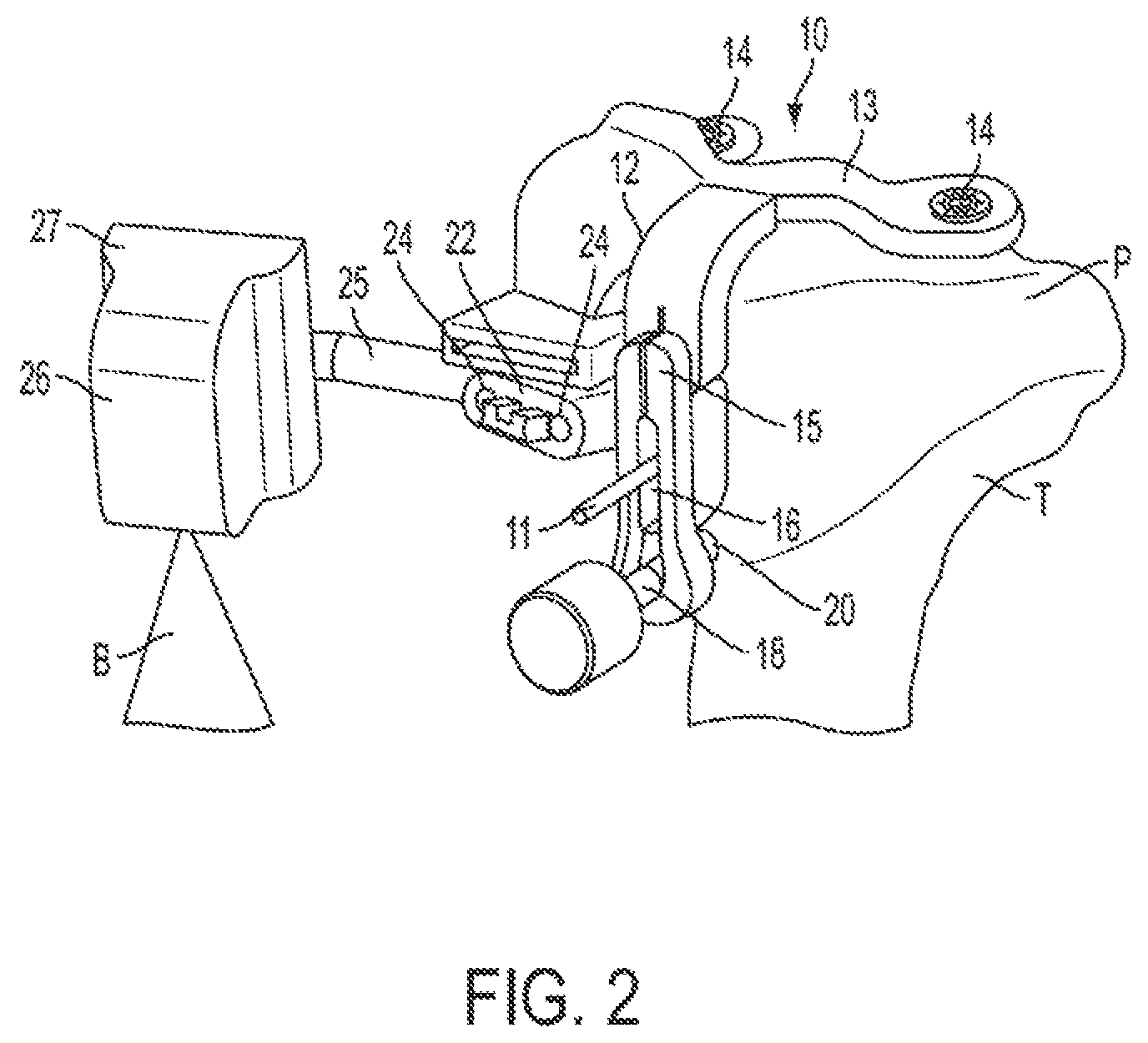
FIG. 2 is front perspective view of a PSI tibial pin guide, produced based on X-rays of the tibia and for use in performing tibial resection during a TKR surgery.
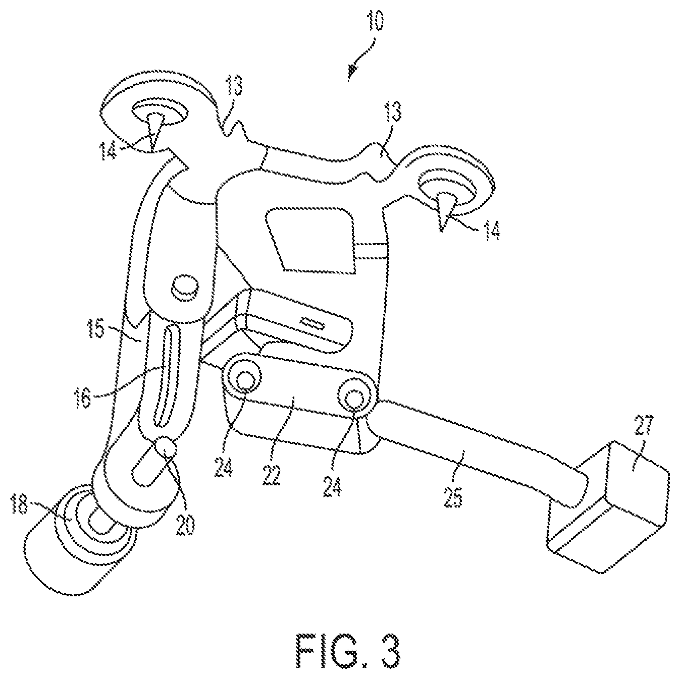
FIG. 3 is a rear perspective view of the PSI tibial pin guide of FIG. 2.
FIG. 4 is a front perspective view of a PSI tibial resection cut guide for use in conjunction with the PSI tibial pin guide of FIG. 2.
FIG. 5 is a top perspective view of a Flexion-Extension alignment boot used in conjunction with the PSI tibial pin guide of FIG. 2.
FIG. 6 is a perspective view of a PSI tibial pin guide jig in accordance with an alternate embodiment of the present disclosure.
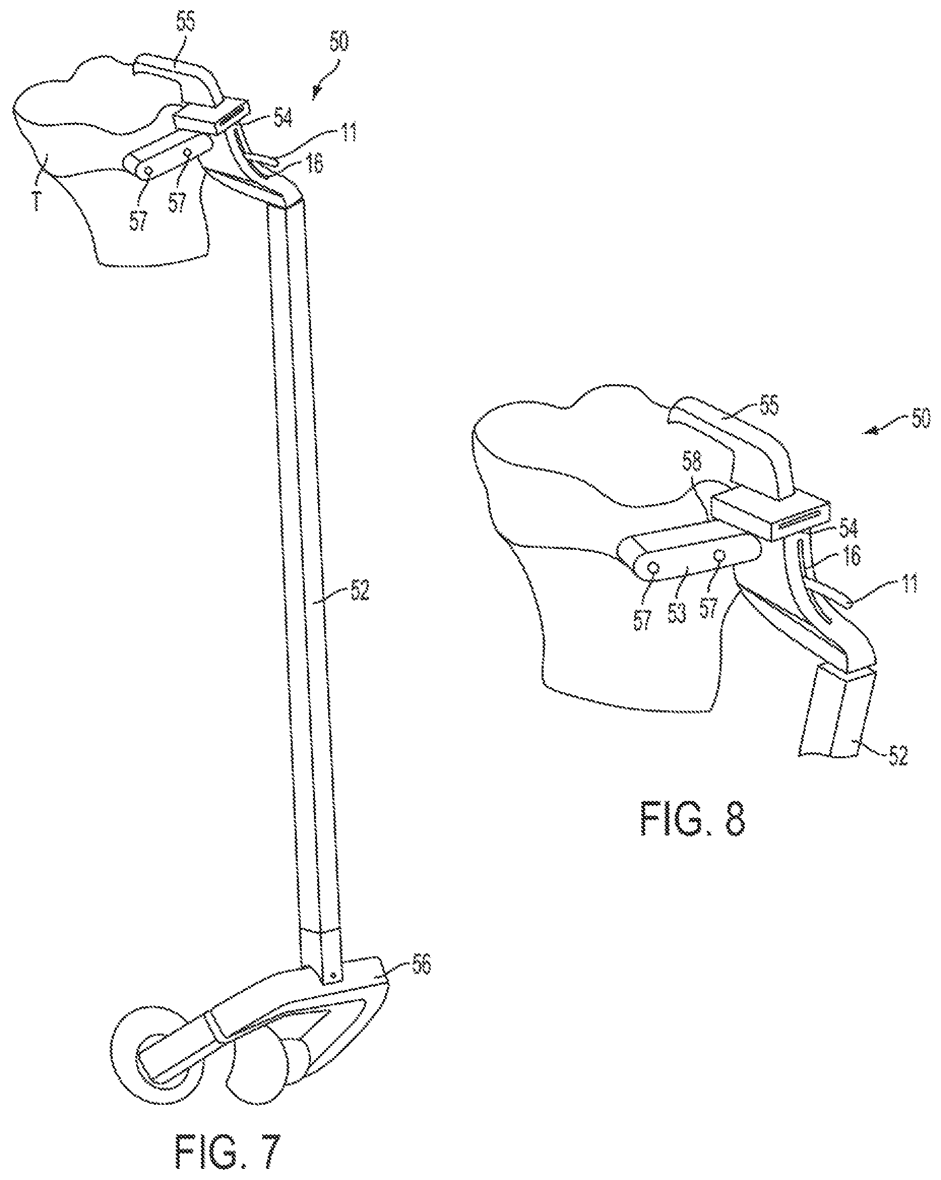
FIG. 7 is a perspective view of a PSI tibial extra-medullary guide in accordance with an embodiment of the present disclosure.
FIG. 8 is a partial perspective view of a proximal portion of the PSI tibial extra-medullary guide of FIG. 7.
FIG. 9 is a perspective view of a tibia mounted PSI hip knee angle (HKA) instrument having a malleoli clamp, in accordance with an embodiment of the present disclosure.
FIG. 10 is a partial perspective view of a proximal portion of the PSI HKA instrument of FIG. 9.
FIG. 11 is a schematic side elevation view of a leg alignment jig for use within the X-ray produced PSI tibial guides of the present disclosure, for use in performing TKR surgery.
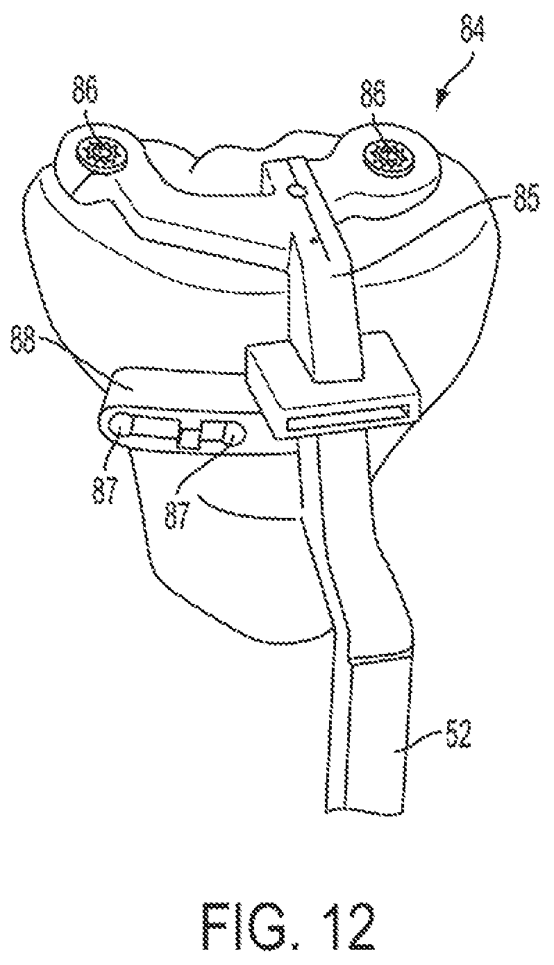
FIG. 12 is a partial perspective view of a proximal portion of a hybrid PSI tibial pin and extra-medullary guide in accordance with another embodiment of the present disclosure.
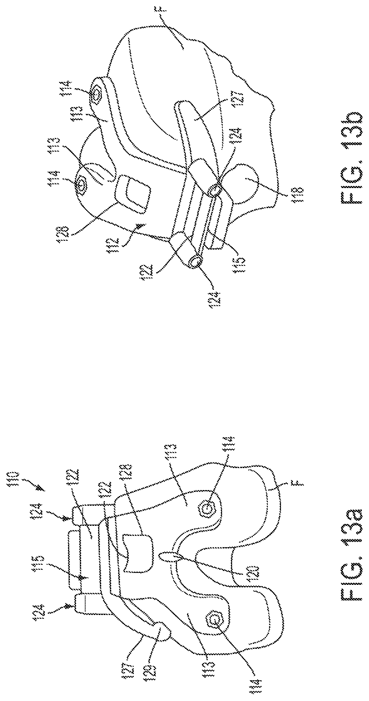
FIG. 13a is a distal end view of a PSI femoral pin guide, produced based on X-rays of the femur and for use in performing femoral resection during a TKR surgery.
FIG. 13b is a partial perspective anterior-medial view of the PSI femoral pin guide of FIG. 13a.
FIG. 14 is a perspective view of a femoral resection cut guide for use in conjunction with the PSI femoral pin guide of FIGS. 13a-13b.
FIG. 15a is a distal perspective view of a PSI anterior-posterior (A-P) sizer in accordance with one embodiment of the present disclosure.
FIG. 15b is a distal perspective view of a PSI A-P sizer in accordance with an alternate embodiment of the present disclosure, shown positioning a posterior cutting guide thereon.
FIG. 15c is a perspective view of an additional instrument for us in re-positioning the posterior cutting guide shown in FIG. 15b.
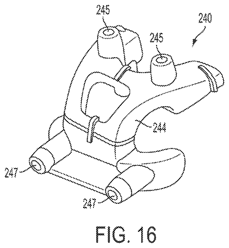
FIG. 16 is a perspective view of a PSI femoral pin guide jig in accordance with an alternate embodiment of the present disclosure.
DETAILED DESCRIPTION
Patient specific instrumentation/instruments/implants (collectively "PSI" as used herein) are purpose designed to suit a specific patient's anatomy, based on a digitized bone model of the anatomy in question. Such PSI devices are most commonly created based on digital bone models that are generated using Magnetic Resonance Imaging (MRI) images of the bone(s) and surrounding soft tissue (e.g. cartilage). MRI scans have to date been largely preferred for the creation of such PSI devices, due to the fact that the MRI scan images are capable of depicting cartilage as well as the bone, thereby ensuring the accuracy of the resulting surgery performed using the PSI device thus produced. However, such MRI scans are both costly and time consuming to conduct.
Accordingly, the present inventors have developed a suite of patient specific surgical implements particularly adapted for use in conducting knee replacement surgery (such as total knee replacement (TKR)), which are specifically designed to be created based on a digital bone model generated only using X-rays taken of the patient's bone(s).
Thus, the presently described system and method enables the creation and use of PSI components for knee surgery which are designed and created using a digital bone model generated using only two-dimensional (2D) X-ray images of the specific patient's bone(s). This enables the PSI components described herein to be created quickly and in a more cost effective manner than with known prior art systems and methods, which require the use of MRI scans to produce the digital bone models.
In accordance with a general aspect of the present disclosure, therefore, a patient specific digital bone model is first created using only X-ray scan images (i.e. no MRI scans are required), so as to digitally reconstruct the bone in a surgical planning computer program and/or a computer assisted surgery (CAS) system. At least two or more X-ray images are required of the patient's bone or bones, which must be taken from different angular positions (e.g. one lateral X-ray and one frontal or anterior X-ray). While one X-ray image may be insufficient, more than two X-ray images may alternately be used. Generally, the greater the number of X-ray scans taken from different angular positions (e.g. lateral, medial, anterior, posterior, etc.), the greater the resulting accuracy of the digital bone model created therefrom. However, the desired accuracy has been found to be obtainable when only two X-rays are taken from perpendicularly disposed angular positions (e.g. lateral and frontal/anterior).
Once a digital bone model is created using the surgical planning computer program and/or CAS system, using only the two or more X-ray images of the bone(s) of the specific patient, a PSI surgical component as described herein is then designed using the CAS system as will be described, and then subsequently created specifically for the patient, using the digital bone model of the patient's anatomy created based only on the X-ray images. The PSI components as described herein may therefore be created, once they have been planned/designed to fit with the digital bone model, out of any suitable material, but these may include plastics or metals which are suitable for use in surgical applications. Ideally, these PSI components are produced rapidly and on site, using an additive manufacturing process such as 3-D printing.
While X-rays are typically perceived as being less precise than MRI images, the present method and system can nevertheless be used to create PSI components which are specially adapted to be formed based on a digitized patient bone model generated using only X-ray images. Thus PSI devices, tool and/or instruments described herein may accordingly be designed and created more time and cost effectively.
As will be seen, because an X-ray generated digital bone model is being used, standard surgical tools, and even previously developed standard patient-specific tools, cannot be readily used. This is because patient specific tools developed based on MRI-generated bone models can be designed knowing precisely where any cartilage and other soft tissue is located. As this is not the case for bone models generated using only X-rays images, any PSI component which is doing to be designed based on such X-ray bone models must be configured in such a way as to maximize the accuracy of the component and more specifically its mounting points with the actual bone, in order to ensure that the end surgical result when this component is used is acceptable.
The presently described PSI components, which are produced based solely on X-ray generated digital bone models, therefore include one or more anchor points thereon that are adapted to abut and/or otherwise engage a surface of the bone and that are disposed on the PSI component at one or more locations corresponding to areas of expected high accuracy on the digital bone model generated by the X-ray scans. These areas of expected high accuracy on the digital bone model will generally correspond to points on a peripheral bone contour in at least one of the angular positions from which an X-ray image is taken. For example, if a frontal, or anterior, X-ray has been taken of the bone, the medial, lateral and proximal outer peripheral contours of the bone will be very accurate in the X-ray image and thus in the resulting digital bone model created thereby. As a result, points on the bone model which are disposed along these medial, lateral and/or proximal peripheral contours of the digital bone model will be areas of expected high accuracy, even if the X-ray image is not capable of revealing any cartilage present. Similarly, if a lateral X-ray has been taken of the bone, the anterior, distal and/or proximal outer peripheral contours of the bone will be very accurate in the X-ray image, and thus in the resulting digital bone model created thereby. As a result, points on the bone model which are substantially disposed along these anterior, distal and proximal outer peripheral contours of the digital bone model will be areas of expected high accuracy, even if the X-ray image is not capable of revealing any cartilage present. Thus, by positioning any anchor or mounting elements of a PSI component in locations on the PSI component which correspond to these areas of expected high accuracy on the X-ray generated bone model, the PSI component so designed is particularly adapted for use without any appreciable loss in accuracy.
The term "anchor", "anchor elements" or "anchor points" as used herein is understood to mean points on the PSI component which engage the bone when the PSI component is mounted thereto, whether this be simply by abutting the bone without being directly fixed thereto (e.g. a bone spike, blade or jack screw which rests on the outer surface of the bone) or by being fastened (e.g. by a pin, bone screw, etc. which penetrates into the bone for rigid fastening thereto). The term "anchor" as used herein therefore does not necessarily imply rigid fastening by penetration of the bone, but rather such anchors fix the PSI component in place on the bone such that relative movement therebetween is not readily possible.
Referring now to the Figures, these general aspects of the present disclosure as outlined above are described and depicted in greater detail with reference to an exemplary orthopedic knee surgery system, and more particularly with respect to performing a total knee replacement (TKR) system involving components and methods specific to both tibia and femur resection and prosthetic reconstruction.
This may include, for example, providing PSI tools and/or implants, formed in order to correspond with the patient specific digital bone model created based on X-ray images. This may further include digitizing the tibial and/or femoral mechanical axis in order to be able to perform the TKR procedure on the patient using the PSI tools. This may be done in conjunction with a CAS system, for example one which employs inertial-based or micro-electro-mechanical sensor (MEMS) trackable members for use in orthopedic surgical applications. The presently described system, surgical tools and methods may therefore be used in conjunction with an inertial-based CAS system employing trackable members having inertial-based sensors, such as the MEMS-based system and method for tracking a reference frame disclosed in United States Patent Application Publication No. US 2011/0218458, and the MEMS-based system and method for planning/guiding alterations to a bone disclosed in U.S. Pat. Nos. 8,265,790 and 8,718,820, and in United States Patent Application Publication No. 2009/0247863, the entire contents of each of which is incorporated herein by reference. However, it is to be understood that the tools and methods described herein may also be used with other CAS systems. The present systems and methods may also be used in conjunction with a tool for digitizing a mechanical axis of a tibia using a CAS system, as described in U.S. Pat. No. 8,551,108, the entire content of which is incorporated herein by reference.
The PSI components of the present disclosure are all particularly adapted for use during orthopedic knee surgery, such as TKR, and as such the surgical components of the present suite of surgical tools will now be described below generally as either tibial or femoral components, respectively adapted for use in the positioning of a resection cutting guide on either the tibia or the femur, for the purposes of preparing the bone for receipt of a prosthetic knee replacement implant. While the actual steps of the TKR surgery are as per those well known by those skilled in the art, the presently described PSI components differ in that they are specifically adapted for use in a system and method which has produced the digital bone model using only X-ray images.
Tibial Components
In order to be able to resect a proximal end of the tibia T using a resection cutting guide 30, as shown in FIG. 4, locating pins 31 must first be accurately positioned at the desired position and orientation relative to the tibia T, such that the resulting resection cut will be made at the correct position and angle to accept the planned prosthetic tibial implant. Accordingly, several different embodiments will now be presented, each of which can be used to position these locating pins 31.
In the embodiment of FIGS. 2-3, a PSI tibial pin guide 10 is shown which is produced based on at least two X-rays of the tibia, taken from two different angular positions as described above. The PSI tibial pin guide 10 includes generally a body 12 including a distally extending portion 15 and a pair of posteriorly extending arms 13. The distally extending portion 15 of the body 12 has a slot 16 formed therein, which extends fully through the distally extending portion 15 and is adapted to receive therethrough an anterior bone pin 11. The slot 16 has a transverse width, in the medial-lateral (M-L) direction, substantially similar although just slightly greater than the diameter of the anterior pin 11. The slot 16 has a length, in the proximal-distal (P-D) direction, that is at least several times the diameter of the anterior pin 11. As such, once the anterior pin is fastened in place in the anterior surface of the tibia T, the PSI tibial pin guide 10 can be mounted thereto by inserting the anterior pin 11 through the slot 16 in the body 12 of the PSI tibial pin guide 10. Given the slot's length, the body 12 of the PSI tibial pin guide 10 can therefore be slid in the P-D direction relative to the fixed anterior pin 11 as required. Although only the anterior pin 11, and not the body 12 of the PSI tibial pin guide 10, is engaged to the bone, this pin-slot engagement nevertheless locates, or constrains, the rotation of the PSI tibial pin guide 10 (i.e. relative to longitudinal axis of the bone) while still permitting angular movement in the Varus-Valgus (V-V) and Flexion-Extension (F-E) orientations/directions.
At an upper end of the body 12 of the PSI tibial pin guide 10, the pair of posteriorly extending arms 13 each have a proximal anchor element 14 disposed near the remote end thereof, the two proximal anchor elements 14 comprising bone spikes or nails. These bone spikes 14 are adapted to penetrate any cartilage on the tibial plateaus P and engage, but not substantially penetrate, the underlying bone surface of the tibial plateau P. These proximal bone anchors 14 accordingly locate, or constrain, the PSI tibial pin guide 10 in the V-V orientation relative thereto.
The remaining angular constraint required, and for which adjustment is provided, for the PSI tibial pin guide 10 is in the F-E direction. Accordingly, the PSI tibial pin guide 10 includes an adjustment jack screw 18 disposed at a remote end of the distally extending portion 15 of the body 12, which has a bone abutting tip 20 thereon that forms another anchor point or anchor element for abutting the tibia T. By rotating the jack screw 18, the position of the body 12 of the PSI tibial pin guide 10 relative to the tibia T can be adjusted in the F-E direction/orientation.
Accordingly, the PSI tibial pin guide 10 includes one or more anchor elements disposed at different anchor points. In this case, at least three anchor elements are provided, namely the two bone spikes 14 which abut medially-laterally opposite sides of the tibial plateau P and the distally located jack screw 18. Importantly, each of these anchor elements is disposed at a location on the PSI tibial pin guide 10 which corresponds to, or more particularly overlies, point on the bone which correspond to areas of expected high accuracy on the X-ray generated bone model. More particularly, the two bone spikes 14 are located substantially along a proximal bone peripheral contour as defined in a frontal X-ray image taken of the tibia T, and the distal jack screw 18 is located substantially along an anterior bone peripheral contour as defined in a medial or a lateral X-ray image take of the tibia T.
The body 12 of the PSI tibial pin guide 10 also includes a pin guide element 22 disposed at a distal end of a portion of the body adjacent the distally extending portion 15. A pair of pin guide holes 24 extend through the pin guide element 22, and are configured to receive therethrough the bone pins 31 which are used to mount the resection cutting block 30 to the tibia (see FIG. 4).
The PSI tibial pin guide 10 also includes an optical positioning element which is used to position the PSI tibial pin guide 10 in the desired location relative to the tibia T. This optical positioning element includes a laser 26 which is engaged to a laser mount 27 disposed on an extension bar 25 protruding from the body 12 of the PSI tibial pin guide 10. The laser 26 produces a laser beam B, which may be either a point laser beam or a planar beam as shown in FIG. 2. The laser 26 is positioned such that its laser beam B projects onto the ankle and/or foot of the patient. By aligning the laser beam B with either anatomical landmarks on the foot (such as the malleoli of the ankle, for example) or other reference points or markings on another object substantially fixed relative to the ankle (such as the ankle boot 40 as shown in FIG. 5, for example), the user can position the PSI tibial pin guide 10, and therefore the pin guide holes 24 of the pin guide element 22 in a predetermined location which will result in the pins 31, when inserted through the pin guide holes 24 and fastened into the bone, to position the resection cutting block 30 mounted to these pins 31 in a selected position and orientation to perform the proximal resection cut of the tibia.
Referring more specifically to FIG. 5, the boot 40 may optionally be used in order to serve as a reference guide for aligning the PSI tibial pin guide 10 using the laser 26 as described above. More particularly, the boot 40 may include markings or other visually identifiable demarcations, with which the laser beam B of the laser 26 can be aligned, thereby providing additional guidance to the user as the correct alignment of the laser, and thus the PSI tibial pin guide 10 to which it is fixed, in the F-E direction.
Because the tibial pin guide 10 is a PSI component, it is designed and configured to tailor to the specific anatomical features of the tibia T to which it is intended to be mounted. Therefore, while each tibial pin guide 10 will be slightly different to accommodate particularities of each patient's bone, they nevertheless include one or more anchor points thereon that are adapted to abut and/or otherwise engage a surface of the tibia T and that are disposed at one or more locations of the PSI tibial pin guide 10 which correspond to areas of expected high accuracy on a digital bone model generated only by X-ray scans.
Referring now to FIG. 4 in more detail, a PSI tibial resection cut guide 30 of the present system is shown which including a cutting block 32 having a saw slot 37 extending therethrough and a base block 34 that is itself fastened in place on the tibia T using the cut guide pins 31. The pins 31 are positioned and fixed in place as described above using the PSI tibial pin guide 10. The cutting block 32 is adjustable in one or more directions relative to the base block 34, using a locking adjustment mechanism 38. In the embodiment as shown in FIG. 4, this locking adjustment mechanism 38 includes a stem 33 which forms part of the cutting block 32 and a mating opening in the base block 34 through which the stem extends. A locking screw 35 is used to fix the base block 34 to the stem 33 of the cutting block 33, such as to prevent relative movement therebetween when the screw is tightened. As the stem 33 can slide within the opening in the base block, the cutting block 32 can accordingly be displaced in a proximal-distal direction, in order to increase or decrease the depth of the proximal resection cut as required. Accordingly, once the pins 31 are in place, the base block 34 is slid onto the pins 31, whereupon the position of the cutting block 32 relative to the fixed base block 34 can be adjusted as required. Once the predetermined position for the cutting guide slot 37, and therefore the cutting block 32, is reached, the locking mechanism 38 is actuated to fix the cutting block 32 in the appropriate position.
FIG. 6 shows a PSI tibial pin guide jig 40 in accordance with an alternate embodiment of the present disclosure. This PSI jig 40 may be alternately used to align and position the mounting pins 31 for the PSI tibial resection cut guide 30, however provides less adjustment features. The PSI tibial guide jig 40 is more akin to pin placement jigs used in conjunction with MRI-generated digital bone models. Nonetheless, however, the PSI tibia pin guide jig 40 is specifically designed to be used with digital bone model generated only using X-ray images.
Accordingly, the PSI jig 40 also includes one or more anchor elements disposed at different anchor points, which in this embodiment includes two bone spikes 41 which abut medially-laterally opposite sides of the tibial plateau and an anterior abutting element 43 disposed on the distally extending body 44. A pair of pin holes 45 also extend through the body 44, and are used as described above to position the pins 31 used to mount the resection cutting block 30 to the tibia. Much as per the PSI tibial pin guide 10 described above, each of the anchor elements of the PSI jig 40 is disposed at a location on the PSI component which corresponds to, or more particularly overlies, a point on the bone which is disposed in areas of expected high accuracy on the X-ray generated digital bone model.
Referring now to FIGS. 7-8, an alternate PSI component of the presently proposed suite of surgical implements is shown, which could alternately be used instead of the PSI tibial pin guide 10 or the PSI jig 40. In this embodiment, a PSI tibial extra-medullary (E-M) guide 50 (or simply "PSI E-M guide") is provided, which can be similarly used to accurately position the pins 31 to be used to mount the resection cutting guide 30 to the proximal end of the tibia T. The PSI E-M guide 50 differs from the previously described pin guides in that it includes an elongated rigid alignment rod 52 which extends distally from the upper mounting body 54, and which has a malleoli clamping element 56 at its distal end. While the alignment rod 52 may be standardized across all, or at least a number of patient sub-populations, each of the opposed end portions, namely the proximal mounting body 54 and the distal malleoli clamping element 56, is a PSI component that is purposed designed based on the anatomical features and needs of the individual patient. One of the possible benefits of the PSI E-M guide 50 is that it permits a less invasive surgical procedure (i.e. minimally invasive surgery), because no arms having spikes are included for contact with the tibial plateau. Accordingly, less of the bone needs to be accessed for engagement of the PSI E-M guide 50 thereto.
Much as per the PSI tibial pin guide 10 described above, however, the PSI E-M guide 50 is first located relative to the tibia T by an anterior pin 11 which mates within a corresponding slot 16 formed, in this case, in the proximal body 54 of the PSI E-M guide 50. This pin-slot engagement between the anterior pin 11 and the proximal body 54 of the PSI E-M guide 50 sets, or constrains, the rotation of the device. The proximal body 54 also includes a posteriorly extending finger 55 which includes a visual guide, such as an arrow marking or shape for example, which can be aligned with a known mechanical axis entry point on the tibia T so permit for the verification of the alignment with the mechanical axis of the tibia, thereby permitting the V-V alignment of the of the PSI E-M guide 50.
A posterior abutting element 58 is disposed behind the proximal body 54 of the PSI E-M guide 50, and provides an anchor element which abuts the anterior surface of the tibia T for positioning the component relative thereto. This abutting anchor element 58 is accordingly disposed at a location on the PSI component which corresponds to a point on the bone which is disposed in an area of expected high accuracy on the X-ray generated digital bone model (namely, along the anterior peripheral contour of the proximal tibia). The proximal body also includes a medially extending portion 53 having two pin holes 57 extending therethrough for receiving, and thus positioning, the pins 31 used to mount the resection cutting guide 30 thereto.
Although the relative orientation of the pins 31 can be varied somewhat when using the PSI E-M guide 50, it is otherwise not readily adjustable (e.g. in height, etc). Rather, because both the distal malleoli clamp 56 and the proximal body 54 are both PSI components purposed design for the individual bone, the PSI E-M guide 50 can be designed such as to be accurately mounted to the tibia T to allow the pins 31 to be inserted through the guide holes 57 in their determined position and orientation.
Referring now to FIGS. 9-10, another alternate PSI component of the presently proposed suite of surgical implements is shown, which could alternately be used instead of the PSI tibial pin guide 10, the PSI jig 40 or the PSI E-M guide 50. In this embodiment, a PSI hip-knee-ankle (HKA) instrument 60 is provided, which can be similarly used to accurately position the pins 31 to be used to mount the resection cutting guide 30 to the proximal end of the tibia T. The PSI HKA instrument 60 includes an elongated rigid alignment rod 52, of fixed length, which extends distally from an upper mounting body 64 and which has a malleoli clamping element 56 at its distal end, much as per the PSI E-M guide 50 described above. Accordingly, the PSI malleoli clamping element 56 is used to clamp the component onto the malleoli of the patient, thereby aligning the instrument with the mechanical axis of the tibia.
In contrast to the previously described instruments, however, the proximal end of PSI HKA instrument 60 engages both the tibia and the femur, as seen in FIGS. 9 and 10. More particularly, the PSI proximal mounting body 64 of the PSI HKA instrument 60 includes both a tibial portion 66 and a femoral portion 68.
The tibial portion 66 is engaged in place relative to the tibia using an anterior pin 11 which is received within a corresponding slot 16, in the same manner as described above with the previously tibial instruments. This pin-slot engagement between the anterior pin 11 and the slot 16 in the tibial portion 66 of the PSI proximal body 64 sets, or constrains, the rotation of the device.
A posterior abutting element 70 is disposed behind the tibial portion 66 of the PSI proximal body 64, and provides an anchor element which abuts the anterior surface of the tibia T for positioning the component relative thereto. This abutting anchor element 70 is accordingly disposed at a location on the PSI component which corresponds to a point on the tibia which is disposed in an area of expected high accuracy on the X-ray generated digital bone model (namely, along the anterior peripheral contour of the proximal tibia). The tibial portion 66 of the PSI proximal body 64 also includes a medially extending portion 73 having two pin holes 71 extending therethrough for receiving, and thus positioning, the pins 31 used to mount the resection cutting guide 30 to the tibia T.
The femoral portion 68 of the PSI proximal mounting body 64 of the PSI HKA instrument 60 is interconnected with the tibial portion 66 by a sliding and/or pivoting joint connection which allows for one or more of relative P-D and F-E displacement between the two portions 66 and 68, but does not allow for relative angular rotation therebetween. More particularly, the uppermost end of the tibial portion 66 forms a plate 72 which is received within a corresponding slot 74 formed in the lower end of the femoral portion 68. The slot 74 therefore defines two spaced apart flanges 75 between which the plate 72 is received. Two holes 73 are provided in each of the flanges 75, and two correspondingly sized holes (not visible) are also defined through the plate 72. These holes may be aligned, such that a pivot pin is fed therethrough. Accordingly, without any such pivot pin in place, this joint between the tibial and femoral portions 66 and 68 allows for relative sliding displacement therebetween, substantially in the proximal-distal direction. However, when a single pin is disposed through one of the pin holes 73 and the corresponding hole in the plate 72, a pivoting interconnection between the two portions 66, 68 is thereby formed. This accordingly allows for relative rotation therebetween in the flexion-extension plane. Further, if a second pin is disposed through the other of the two pin holes 73 and the corresponding hole in the plate 72, no further rotation is permitted between the tibial portion 66 and the femoral portion 68 of the PSI proximal mounting body 64. This adjustment mechanism therefore provides adjustment flexibility in order to be able to selectively displace (e.g. translate or rotate), or lock, the tibial portion 66 and the femoral portion 68 of the PSI body 64 with respect to each other.
The femoral portion 68 of the PSI proximal mounting body 64 also includes a pair of pin holes 76 which extend through the body thereof and receive pins 31 therethrough for mounting a resection cutting guide to the femur, once the PSI HKA instrument 60 is positioned in place. The resection cutting guide may be the same PSI resection cutting guide 30 as described above (see FIG. 4), or alternately a different one specific for the femur. In order to accurate locate the femoral portion 68 of the PSI proximal mounting body 64, it also includes a proximally extending blade 78 having a femur abutting anchor element 80 thereon. In the same manner as those previously describe above, the femur abutting anchor element 80 is also disposed at a location on the PSI component which corresponds to a point on the bone (in this case the femur) which is disposed in an area of expected high accuracy on the X-ray generated digital bone model (namely, in this case, along the anterior peripheral contour of the distal femur).
When using the PSI HKA instrument 60, the pins for the tibial resection are positioned, aligned and fixed in place in the same manner as per the PSI E-M guide 50 described above. However, in order to also correctly locate the PSI HKA instrument 60 to allow for pins for the femoral resection to be positioned in the desired position and orientation, both the tibia T and femur F are preferably positioned in the same relative orientation as when the X-ray scans were taken. Accordingly, in order to do so, a leg alignment jig 82 may be provided, as shown in FIG. 11. The leg alignment jig 82 is thus configured such as to position the leg of the patient, and thus the tibia T and femur F thereof, in a substantially identical relative position as when the X-ray scans were taken of the bones. The leg alignment jig 82 therefore allows the surgeon to set the leg as it was taken during the X-ray, thereby providing the best positioning for reproducing the planning and therefore maximizing precision of the operation. While the use of such a leg alignment jig 82 is not necessary, it may be useful to use this additional component for the reasons above.
Given that the PSI HKA instrument 60 is also used to locate the pins for mounting to the femur, the PSI HKA instrument 60 can also be used in conjunction with the adjustable femoral resection cutting guide 130 of FIG. 14, and the PSI A-P sizers 210 and 310 of FIGS. 15a and 15b.
FIG. 12 depicts a final embodiment of a PSI tibial pin guide component, which is a hybrid PSI pin and E-M guide 84. Essentially, this embodiment is a combination of the PSI tibial pin guide 10 and the PSI E-M guide 50. However, the PSI pin and E-M guide 84 differs in that it does not use or require an anterior locating pin 11, as per the
References
D00000
D00001
D00002
D00003
D00004
D00005
D00006
D00007
D00008
D00009
D00010
D00011
D00012

D00013
XML
uspto.report is an independent third-party trademark research tool that is not affiliated, endorsed, or sponsored by the United States Patent and Trademark Office (USPTO) or any other governmental organization. The information provided by uspto.report is based on publicly available data at the time of writing and is intended for informational purposes only.
While we strive to provide accurate and up-to-date information, we do not guarantee the accuracy, completeness, reliability, or suitability of the information displayed on this site. The use of this site is at your own risk. Any reliance you place on such information is therefore strictly at your own risk.
All official trademark data, including owner information, should be verified by visiting the official USPTO website at www.uspto.gov. This site is not intended to replace professional legal advice and should not be used as a substitute for consulting with a legal professional who is knowledgeable about trademark law.