Multiple access in wireless telecommunications system for high-mobility applications
Rakib , et al.
U.S. patent number 10,716,095 [Application Number 16/153,577] was granted by the patent office on 2020-07-14 for multiple access in wireless telecommunications system for high-mobility applications. This patent grant is currently assigned to Cohere Technologies, Inc.. The grantee listed for this patent is Cohere Technologies, Inc.. Invention is credited to Ron Hadani, Shlomo Rakib.


View All Diagrams
| United States Patent | 10,716,095 |
| Rakib , et al. | July 14, 2020 |
Multiple access in wireless telecommunications system for high-mobility applications
Abstract
A wireless telecommunications system that mitigates infrasymbol interference due to Doppler-shift and multipath and enables multiple access in one radio channel. Embodiments of the present invention are particularly advantageous for wireless telecommunications systems that operate in high-mobility environments, including high-speed trains and airplanes.
| Inventors: | Rakib; Shlomo (Saratoga, CA), Hadani; Ron (Austin, TX) | ||||||||||
|---|---|---|---|---|---|---|---|---|---|---|---|
| Applicant: |
|
||||||||||
| Assignee: | Cohere Technologies, Inc.
(Santa Clara, CA) |
||||||||||
| Family ID: | 58738443 | ||||||||||
| Appl. No.: | 16/153,577 | ||||||||||
| Filed: | October 5, 2018 |
Prior Publication Data
| Document Identifier | Publication Date | |
|---|---|---|
| US 20190159177 A1 | May 23, 2019 | |
Related U.S. Patent Documents
| Application Number | Filing Date | Patent Number | Issue Date | ||
|---|---|---|---|---|---|
| 15410622 | Jan 19, 2017 | 10098092 | |||
| 62316243 | Mar 31, 2016 | ||||
| 62316298 | Mar 31, 2016 | ||||
| Current U.S. Class: | 1/1 |
| Current CPC Class: | H04L 5/0023 (20130101); H04L 27/2697 (20130101); H04L 5/0016 (20130101); H04L 1/0018 (20130101); H04L 27/265 (20130101); H04J 11/003 (20130101); H04L 27/2655 (20130101); H04L 25/03006 (20130101); H04L 25/03834 (20130101); H04L 27/2626 (20130101); H04B 1/0475 (20130101); H04L 5/0044 (20130101); H04L 27/04 (20130101); H04W 72/04 (20130101); H04L 27/2634 (20130101); H04L 5/0014 (20130101); H04L 23/02 (20130101); H04B 1/62 (20130101); H04L 27/06 (20130101); H04B 15/00 (20130101) |
| Current International Class: | H04W 56/00 (20090101); H04L 1/00 (20060101); H04L 27/04 (20060101); H04J 11/00 (20060101); H04L 5/00 (20060101); H04L 27/26 (20060101); H04L 25/03 (20060101); H04W 72/04 (20090101); H04B 1/62 (20060101); H04B 1/04 (20060101); H04L 23/02 (20060101); H04L 27/06 (20060101); H04B 15/00 (20060101) |
| Field of Search: | ;370/329 |
References Cited [Referenced By]
U.S. Patent Documents
| 4754493 | June 1988 | Coates |
| 5083135 | January 1992 | Nagy et al. |
| 5182642 | January 1993 | Gersdorff et al. |
| 5623511 | April 1997 | Bar-David et al. |
| 5831977 | November 1998 | Dent |
| 5835529 | November 1998 | Koga et al. |
| 5872542 | February 1999 | Simons et al. |
| 5956624 | September 1999 | Hunsinger et al. |
| 6055415 | April 2000 | Suzuki |
| 6212246 | April 2001 | Hendrickson |
| 6289063 | September 2001 | Duxbury |
| 6356555 | March 2002 | Rakib et al. |
| 6381234 | April 2002 | Sakoda et al. |
| 6388621 | May 2002 | Lynch |
| 6426983 | July 2002 | Rakib et al. |
| 6608864 | August 2003 | Strait |
| 6631168 | October 2003 | Izumi |
| 6704366 | March 2004 | Combes et al. |
| 6956814 | October 2005 | Campanella |
| 7010048 | March 2006 | Shattil |
| 7327812 | February 2008 | Auer |
| 7392018 | June 2008 | Ebert et al. |
| 7689049 | March 2010 | Monro |
| 7773685 | August 2010 | Tirkkonen et al. |
| 7864877 | January 2011 | Hottinen |
| 8229017 | July 2012 | Lee et al. |
| 8259845 | September 2012 | Dent |
| 8401131 | March 2013 | Fety et al. |
| 8547988 | October 2013 | Hadani et al. |
| 8619892 | December 2013 | Vetter et al. |
| 8717210 | May 2014 | Eldar et al. |
| 8879378 | November 2014 | Rakib et al. |
| 8892048 | November 2014 | Turner |
| 8976851 | March 2015 | Hadani et al. |
| 9031141 | May 2015 | Hadani et al. |
| 9071285 | June 2015 | Hadani et al. |
| 9071286 | June 2015 | Hadani et al. |
| 9083483 | July 2015 | Rakib et al. |
| 9083595 | July 2015 | Rakib et al. |
| 9130638 | September 2015 | Hadani et al. |
| 9282528 | March 2016 | Hashimoto |
| 9294315 | March 2016 | Hadani et al. |
| 9444514 | September 2016 | Hadani et al. |
| 9479381 | October 2016 | Siohan et al. |
| 9548840 | January 2017 | Hadani et al. |
| 9553984 | January 2017 | Krause et al. |
| 9590779 | March 2017 | Hadani et al. |
| 9634719 | April 2017 | Rakib et al. |
| 9660851 | May 2017 | Hadani et al. |
| 9668148 | May 2017 | Hadani et al. |
| 9712354 | July 2017 | Hadani et al. |
| 9729281 | August 2017 | Hadani et al. |
| 2001/0031022 | October 2001 | Petrus et al. |
| 2001/0033614 | October 2001 | Hudson |
| 2001/0046205 | November 2001 | Easton et al. |
| 2002/0001308 | January 2002 | Heuer |
| 2002/0034191 | March 2002 | Shattil |
| 2002/0181388 | December 2002 | Jain et al. |
| 2002/0181390 | December 2002 | Mody et al. |
| 2002/0181607 | December 2002 | Izumi |
| 2003/0073464 | April 2003 | Giannakis et al. |
| 2003/0185295 | October 2003 | Yousef |
| 2003/0235147 | December 2003 | Walton et al. |
| 2004/0044715 | March 2004 | Aldroubi et al. |
| 2004/0174812 | September 2004 | Murakami et al. |
| 2004/0189581 | September 2004 | Sako et al. |
| 2004/0218523 | November 2004 | Varshney et al. |
| 2005/0157778 | July 2005 | Trachewsket et al. |
| 2005/0157820 | July 2005 | Wongwirawat et al. |
| 2005/0180517 | August 2005 | Abe |
| 2005/0207334 | September 2005 | Hadad |
| 2005/0251844 | November 2005 | Marione et al. |
| 2006/0008021 | January 2006 | Bonnet |
| 2006/0039270 | February 2006 | Strohmer et al. |
| 2007/0014272 | January 2007 | Palanki et al. |
| 2007/0038691 | February 2007 | Candes et al. |
| 2007/0078661 | April 2007 | Sriram |
| 2007/0104283 | May 2007 | Han et al. |
| 2007/0110131 | May 2007 | Guess et al. |
| 2007/0211952 | September 2007 | Faber et al. |
| 2007/0237181 | October 2007 | Cho et al. |
| 2007/0253465 | November 2007 | Muharemovic et al. |
| 2007/0253504 | November 2007 | Hasegawa |
| 2008/0043857 | February 2008 | Dias et al. |
| 2008/0117999 | May 2008 | Kadous et al. |
| 2008/0186843 | August 2008 | Ma et al. |
| 2008/0187062 | August 2008 | Pan et al. |
| 2008/0232504 | September 2008 | Ma et al. |
| 2008/0310383 | December 2008 | Kowalski |
| 2009/0080403 | March 2009 | Hamdi |
| 2009/0092259 | April 2009 | Jot et al. |
| 2009/0103593 | April 2009 | Bergamo |
| 2009/0122854 | May 2009 | Zhu et al. |
| 2009/0161804 | June 2009 | Chrabieh et al. |
| 2009/0204627 | August 2009 | Hadani |
| 2009/0222226 | September 2009 | Baraniuk et al. |
| 2009/0303961 | December 2009 | Popovic et al. |
| 2010/0001901 | January 2010 | Baraniuk et al. |
| 2010/0008432 | January 2010 | Kim et al. |
| 2010/0027608 | February 2010 | Priotti |
| 2010/0111138 | May 2010 | Hosur et al. |
| 2010/0142476 | June 2010 | Jiang et al. |
| 2010/0187914 | July 2010 | Rada et al. |
| 2010/0238787 | September 2010 | Guey |
| 2010/0277308 | November 2010 | Potkonjak |
| 2010/0303136 | December 2010 | Ashikhmin et al. |
| 2010/0322349 | December 2010 | Lee et al. |
| 2011/0007789 | January 2011 | Garmany |
| 2011/0110532 | May 2011 | Svendsen |
| 2011/0116489 | May 2011 | Grandhi |
| 2011/0116516 | May 2011 | Hwang et al. |
| 2011/0126071 | May 2011 | Han et al. |
| 2011/0131463 | June 2011 | Gunnam |
| 2011/0216808 | September 2011 | Tong et al. |
| 2011/0286502 | November 2011 | Adachi et al. |
| 2011/0287778 | November 2011 | Levin et al. |
| 2011/0292971 | December 2011 | Hadani et al. |
| 2011/0293030 | December 2011 | Rakib et al. |
| 2011/0299379 | December 2011 | Sesia et al. |
| 2011/0305267 | December 2011 | Rius et al. |
| 2012/0021769 | January 2012 | Lindoff et al. |
| 2012/0051457 | March 2012 | Ma et al. |
| 2012/0140716 | June 2012 | Baldemair et al. |
| 2012/0170684 | July 2012 | Yim et al. |
| 2012/0201322 | August 2012 | Rakib et al. |
| 2012/0213098 | August 2012 | Sun |
| 2012/0235795 | September 2012 | Liao et al. |
| 2012/0269201 | October 2012 | Atungsin et al. |
| 2012/0272117 | October 2012 | Stadelmeier et al. |
| 2012/0320994 | December 2012 | Loghin et al. |
| 2013/0021977 | January 2013 | Yang et al. |
| 2013/0058390 | March 2013 | Haas et al. |
| 2013/0077579 | March 2013 | Cho et al. |
| 2013/0083661 | April 2013 | Gupta et al. |
| 2013/0121497 | May 2013 | Smaragdis et al. |
| 2013/0230010 | September 2013 | Kim et al. |
| 2013/0260787 | October 2013 | Hashimoto |
| 2013/0279627 | October 2013 | Wu et al. |
| 2013/0315133 | November 2013 | Wang et al. |
| 2014/0143639 | May 2014 | Loghin et al. |
| 2014/0161154 | June 2014 | Hadani et al. |
| 2014/0169385 | June 2014 | Hadani et al. |
| 2014/0169406 | June 2014 | Hadani et al. |
| 2014/0169433 | June 2014 | Hadani et al. |
| 2014/0169436 | June 2014 | Hadani et al. |
| 2014/0169437 | June 2014 | Hadani et al. |
| 2014/0169441 | June 2014 | Hadani et al. |
| 2014/0247803 | September 2014 | Arambepola et al. |
| 2014/0348252 | November 2014 | Siohan et al. |
| 2014/0364128 | December 2014 | Lee et al. |
| 2015/0080725 | March 2015 | Wegner |
| 2015/0117395 | April 2015 | Hadani et al. |
| 2015/0326273 | November 2015 | Rakib et al. |
| 2015/0327085 | November 2015 | Hadani et al. |
| 2015/0382231 | December 2015 | Jabbar et al. |
| 2016/0043835 | February 2016 | Hadani et al. |
| 2016/0135132 | May 2016 | Donepudi et al. |
| 2016/0157146 | June 2016 | Karabinis |
| 2016/0182269 | June 2016 | Hadani et al. |
| 2016/0191217 | June 2016 | Hadani et al. |
| 2016/0191280 | June 2016 | Hadani et al. |
| 2016/0254889 | September 2016 | Shattil |
| 2016/0277225 | September 2016 | Frenne et al. |
| 2016/0309345 | October 2016 | Tehrani et al. |
| 2016/0380743 | December 2016 | Rakib |
| 2016/0381576 | December 2016 | Hadani et al. |
| 2017/0012749 | January 2017 | Rakib et al. |
| 2017/0012810 | January 2017 | Rakib et al. |
| 2017/0019297 | January 2017 | Rakib |
| 2017/0033899 | February 2017 | Rakib et al. |
| 2017/0040711 | February 2017 | Rakib et al. |
| 2017/0078054 | March 2017 | Hadani et al. |
| 2017/0099122 | April 2017 | Hadani et al. |
| 2017/0099607 | April 2017 | Hadani et al. |
| 2017/0149594 | May 2017 | Rakib |
| 2017/0149595 | May 2017 | Rakib et al. |
| 2017/0201354 | July 2017 | Hadani et al. |
| 2017/0207817 | July 2017 | Hadani et al. |
| 2017/0222700 | August 2017 | Hadani et al. |
| 2017/0230215 | August 2017 | Rakib et al. |
| 2017/0244524 | August 2017 | Hadani et al. |
| 1235720 | Nov 1999 | CN | |||
| 101002448 | Jul 2007 | CN | |||
| 101304276 | Nov 2008 | CN | |||
| 101388872 | Mar 2009 | CN | |||
| 101682316 | Mar 2010 | CN | |||
| 101939935 | Jan 2011 | CN | |||
| 102064852 | May 2011 | CN | |||
| 1432168 | Jun 2004 | EP | |||
| 2011127910 | Jun 2011 | JP | |||
| 2007004297 | Jan 2007 | WO | |||
| 2011137699 | Nov 2011 | WO | |||
| 2011150315 | Dec 2011 | WO | |||
| 2013148546 | Oct 2013 | WO | |||
| 2014004585 | Jan 2014 | WO | |||
| 2016014596 | Jan 2016 | WO | |||
| 2016014598 | Jan 2016 | WO | |||
| 2016176642 | Nov 2016 | WO | |||
| 2016183230 | Nov 2016 | WO | |||
| 2016183240 | Nov 2016 | WO | |||
| 2016209848 | Dec 2016 | WO | |||
| 2017003952 | Jan 2017 | WO | |||
| 2017011478 | Jan 2017 | WO | |||
Other References
|
International Search Report and Written Opinion for International Application No. PCT/US2017/025797, dated Jun. 21, 2017, 6 pages. cited by applicant . International Search Report and Written Opinion for International Application No. PCT/US2016/030259, dated Aug. 4, 2016, 13 pages. cited by applicant . Office Action for U.S. Appl. No. 15/152,464, dated Apr. 6, 2017, 10 pages. cited by applicant . Examination Report No. 1 for Australian Application No. 2013280487, dated May 2, 2016, 3 pages. cited by applicant . International Search Report and Written Opinion for International Application No. PCT/US2016/031928, dated Oct. 7, 2016, 10 pages. cited by applicant . Office Action for U.S. Appl. No. 15/188,946, dated May 8, 2017, 14 pages. cited by applicant . International Search Report and Written Opinion for International Application No. PCT/US2016/038584, dated Sep. 26, 2016, 8 pages. cited by applicant . Office Action for U.S. Appl. No. 15/187,668, dated Feb. 16, 2017, 6 pages. cited by applicant . International Search Report and Written Opinion for International Application No. PCT/US2016/031909, dated Aug. 11, 2016, 13 pages. cited by applicant . Office Action for U.S. Appl. No. 15/194,494, dated May 5, 2017, 16 pages. cited by applicant . International Search Report and Written Opinion for International Application No. PCT/US2016/039662, dated Nov. 29, 2016, 14 pages. cited by applicant . Office Action for U.S. Appl. No. 15/436,653, dated Jun. 2, 2017, 10 pages. cited by applicant . Office Action for U.S. Appl. No. 15/208,545, dated Aug. 21, 2017, 15 pages. cited by applicant . International Search Report and Written Opinion for International Application No. PCT/US2016/041940, dated Oct. 20, 2016, 8 pages. cited by applicant . Supplementary European Search Report for European Application No. 13768150.8, dated Oct. 30, 2015, 7 pages. cited by applicant . International Search Report and Written Opinion for International Application No. PCT/US2013/033652, dated Jun. 12, 2013, 8 pages. cited by applicant . International Search Report and Written Opinion for International Application No. PCT/US2015/041417, dated Oct. 1, 2015, 7 pages. cited by applicant . Office Action for U.S. Appl. No. 14/805,407, dated Dec. 14, 2016, 7 pages. cited by applicant . International Search Report and Written Opinion for International Application No. PCT/US2015/041420, dated Oct. 1, 2015, 6 pages. cited by applicant . Office Action for U.S. Appl. No. 13/117,119, dated Aug. 5, 2013, 5 pages. cited by applicant . Notice of Allowance for U.S. Appl. No. 13/117,119, dated Feb. 28, 2014, 13 pages. cited by applicant . Banelli, P. et al., "Modulation Formats and Waveforms for 5G Networks: Who Will Be the Heir of OFDM?," IEEE Signal Processing Magazine, vol. 81, pp. 80-93, Nov. 2014. cited by applicant . El Hattachi, R. et al., "NGMN 5G Initiative White Paper," NGMN Alliance, Feb. 17, 2015. [Online]. Available: https://www.ngmn.org/uploads/media/NGMN_5G_White_Paper_V1_0.pdf, 125 pages. cited by applicant . Rusek, F. et al., "Scaling Up MIMO, Opportunities and Challenges with Very Large Arrays," IEEE Signal Processing Magazine, pp. 40-60 (2013). cited by applicant . Vodafone, "Cellular Internet of Things: Architectural Aspects," RP-150869, 3GPP RAN#68, Malmo, Sweden (Jun. 9, 2015), 19 pages. cited by applicant . Supplementary European Search Report for European Application No. 11787483.4, dated Sep. 9, 2014, 6 pages. cited by applicant . International Search Report and Written Opinion for International Application No. PCT/US2011/038302, dated Nov. 15, 2011, 8 pages. cited by applicant . International Preliminary Report on Patentability for International Application No. PCT/US2011/038302, dated Dec. 4, 2012, 7 pages. cited by applicant . Office Action for U.S. Appl. No. 13/117,124, dated Feb. 22, 2013, 7 pages. cited by applicant . Notice of Allowance for U.S. Appl. No. 13/117,124, dated Aug. 8, 2013, 10 pages. cited by applicant . Office Action for U.S. Appl. No. 14/605,957, dated Jun. 22, 2017, 6 pages. cited by applicant . Supplementary European Search Report for European Application No. 13809004.8, dated Apr. 14, 2016, 8 pages. cited by applicant . Communication Pursuant to Article 94(3) EPC for European Application No. 13809004.8, dated Feb. 17, 2017, 5 pages. cited by applicant . Notice of Allowance for U.S. Appl. No. 13/927,087, dated Feb. 25, 2015, 9 pages. cited by applicant . Office Action for U.S. Appl. No. 13/927,087, dated Nov. 12, 2014, 14 pages. cited by applicant . Gurevich, S. et al. "Group Representation Design of Digital Signals and Sequences," S.W. Golomb et al. (eds.), SETA 2008, LNCS 5203, pp. 153-166, Springer-Verlag Berlin Heidelberg (2008). cited by applicant . International Search Report and Written Opinion for International Application No. PCT/US2013/047723, dated Oct. 29, 2013, 17 pages. cited by applicant . International Preliminary Report on Patentability for International Application No. PCT/US2013/047723, dated Dec. 31, 2014, 15 pages. cited by applicant . Notice of Allowance for U.S. Appl. No. 13/927,088, dated Feb. 18, 2015, 7 pages. cited by applicant . Office Action for U.S. Appl. No. 13/927,088, dated Nov. 28, 2014, 13 pages. cited by applicant . Notice of Allowance for U.S. Appl. No. 13/927,086, dated Dec. 26, 2014, 8 pages. cited by applicant . Supplemental Notice of Allowability for U.S. Appl. No. 13/927,086, dated Mar. 19, 2015, 4 pages. cited by applicant . Office Action for U.S. Appl. No. 13/927,086, dated Oct. 14, 2014, 10 pages. cited by applicant . Office Action for U.S. Appl. No. 13/927,089, dated Dec. 24, 2014, 13 pages. cited by applicant . Office Action for U.S. Appl. No. 13/927,089, dated Aug. 14, 2015, 7 pages. cited by applicant . Supplemental Notice of Allowability for U.S. Appl. No. 13/927,091, dated Jun. 11, 2015, 4 pages. cited by applicant . Notice of Allowance for U.S. Appl. No. 13/927,091, dated Apr. 24, 2015, 8 pages. cited by applicant . Office Action for U.S. Appl. No. 13/927,091, dated Jan. 27, 2015, 15 pages. cited by applicant . Office Action for U.S. Appl. No. 13/927,092, dated Oct. 8, 2014, 5 pages. cited by applicant . Notice of Allowance for U.S. Appl. No. 13/927,092, dated Oct. 24, 2014, 7 pages. cited by applicant . Office Action for U.S. Appl. No. 13/927,095, dated Apr. 30, 2015, 11 pages. cited by applicant . Office Action for U.S. Appl. No. 13/927,095, dated Nov. 4, 2015, 9 pages. cited by applicant . Office Action for U.S. Appl. No. 13/927,095, dated Jun. 1, 2016, 10 pages. cited by applicant . Office Action for U.S. Appl. No. 14/717,886, dated Apr. 19, 2016, 10 pages. cited by applicant . Office Action for U.S. Appl. No. 14/709,377, dated Dec. 11, 2015, 12 pages. cited by applicant . Office Action for U.S. Appl. No. 14/709,377, dated Jul. 13, 2016, 17 pages. cited by applicant . Examination Report No. 1 for Australian Application No. 2013239970, dated Dec. 8, 2015, 3 pages. cited by applicant . "AT&T Annual Report 2014," Opening Our Network [Online]. Retrieved from the Internet: Sep. 22, 2016. <URL: http://www.att.com/Investor/ATT_Annual/2014/att_introduces_new_concepts_f- or_telecom_network_html>, 5 pages. cited by applicant . Catt, "UL ACK/NACK transmission methods for LTE-A," 3GPP TSG RAN WG1 Meeting #60bis, R1-102453, Beijing, China, Apr. 12-16, 2010, 8 pages. cited by applicant . Toskala, A. et al., "Physical Layer," Chapter 5 In: "LTE for UMTS: OFDMA and SC-FDMA Based Radio Access," Holma, H. et al. (eds.), John Wiley & Sons, Ltd., United Kingdom, 2009, pp. 83-135. cited by applicant . Mecklenbrauker, W., "A Tutorial on Non-Parametric Bilinear Time-Frequency Signal Representations," In: Time and Frequency Representation of Signals and Systems, Longo, G. et al. (eds.), Springer-Verlag Wien, vol. 309, pp. 11-68 (1989). cited by applicant . Nehorai, A. et al., "MURI: Adaptive waveform design for full spectral dominance (2005-2010)," AFOSR FA9550-05-1-0443, Final Report, [online], Mar. 11, 2011 Retrieved on May 11, 2013, Retrieved from the Internet <URL: http://oai.dtic.mil/oai/oai?verb=getRecord&metadataPrefix=html&i- dentifier=ADA565420>, 103 pages. cited by applicant . Office Action for Japanese Application No. 2015-518647, dated Jul. 7, 2015, 10 pages. cited by applicant . Office Action for U.S. Appl. No. 14/754,596, dated Apr. 19, 2016, 18 pages. cited by applicant . Office Action for U.S. Appl. No. 14/809,129, dated Jul. 19, 2016, 5 pages. cited by applicant . Office Action for U.S. Appl. No. 15/617,962, dated Sep. 6, 2017, 10 pages. cited by applicant . International Search Report and Written Opinion for International Application No. PCT/US2016/050825, dated Feb. 8, 2017, 12 pages. cited by applicant . International Search Report and Written Opinion for International Application No. PCT/US2016/052524, dated Dec. 20, 2016, 8 pages. cited by applicant . Office Action for U.S. Appl. No. 15/374,995, dated Aug. 7, 2017, 6 pages. cited by applicant. |
Primary Examiner: Chan; Sai Ming
Attorney, Agent or Firm: Perkins Coie LLP
Parent Case Text
STATEMENT OF RELATED APPLICATIONS
This application is a continuation of U.S. patent application Ser. No. 15/410,622, filed on 19 Jan. 2017 which claims benefit of U.S. provisional patent application No. 62/316,243, filed on 31 Mar. 2016, entitled "Robust Wireless Telecommunications System", and U.S. provisional patent application No. 62/316,298, filed on 31 Mar. 2016, entitled "Orthogonal Time Frequency Space" all of which are incorporated by reference.
Claims
What is claimed is:
1. A base station apparatus, comprising: a processor configured to: transmit: (a) a first command to a first wireless terminal to transmit, into a radio channel during a superframe, a first modulated radio-frequency carrier signal that is modulated with: (i) a first waveform .phi.1(m1,n1) of a first waveform array .PHI.1 and a first data item, and (ii) a second waveform .phi.2(m2,n2) of a second waveform array .PHI.2 and a second data item, and (b) a second command to a second wireless terminal to transmit, into the radio channel during the superframe, a second modulated radio-frequency carrier signal that is modulated with: (i) a third waveform .phi.1(m3,n3) of the first waveform array .PHI.1 and a third data item, and (ii) a fourth waveform .phi.2(m4,n4) of the second waveform array .PHI.2 and a fourth data item, and wherein: (i) the waveform .phi.1(m1,n1) is partitioned into N1 time slots, and (ii) the waveform .phi.2(m2,n2) is partitioned into N2 time slot, and (iii) time slot p1 of the waveform .phi.1(m1,n1) comprises a basic waveform b1(m1) multiplied by exp[2.pi.(n1-1)(p1-1)i/N1], and (iv) time slot p2 of the waveform .phi.2(m2,n2) comprises a basic waveform b2(m2) multiplied by exp[2.pi.(n2-1)(p2-1)i/N2], and (v) time slot p3 of the waveform .phi.1(m3,n3) comprises a basic waveform b1(m3) multiplied by exp[2.pi.(n3-1)(p3-1)i/N1], and (vi) time slot p4 of the waveform .phi.2(m4,n4) comprises a basic waveform b2(m4) multiplied by exp[2.pi.(n4-1)(p4-1)i/N2], and (vii) the waveform .phi.1(m1,n1) is multiplied by the first data item, and (viii) the waveform .phi.2(m2,n2) is multiplied by the second data item, and (ix) the waveform .phi.1(m3,n3) is multiplied by the third data item, and (x) the waveform .phi.2(m4,n4) is multiplied by the fourth data item, and (xi) M1, N1, M2, and N2 are positive integers greater than 1, and (xii) m1 and m3 are positive integers in the range m1, m3.di-elect cons.{1, . . . , M1}, and (xiii) m2 and m4 are positive integers in the range m2, m4 E {1, . . . , M2}, and (xiv) n1, n3, p1, and p3 are positive integers in the range n1, n3, p1, and p3.di-elect cons.{1, . . . , N1}, and (xv) n2, n4, p2, and p4 are positive integers in the range n2, n4, p2, and p4.di-elect cons.1, . . . , N2}, and (xvi) M1.noteq.M2; receive, from the radio channel during the superframe, a third modulated radio-frequency carrier signal via an antenna; demodulate the third modulated radio-frequency carrier signal to recover the first data item, the second data item, the third data item, and the fourth data item; and transmit, on an interface to a cellular infrastructure, the first data item and the second data item in association with the first wireless terminal and the third data item and the fourth data item in association with the second wireless terminal.
2. The base station apparatus of claim 1 wherein M2 is an integral multiple of M1 and M1<M2.
3. The base station apparatus of claim 1 wherein N1.noteq.N2.
4. The base station apparatus of claim 1 wherein N2 is an integral multiple of N1 and N1<N2.
5. The base station apparatus of claim 1 wherein waveform .phi.1(m1,n1) and waveform .phi.2(m2,n2) begin at superframe time interval 1.
6. The base station apparatus of claim 1 wherein waveform .phi.1(m1,n1) is frame unaligned with waveform .phi.2(m2,n2) in the modulated radio-frequency carrier signal.
7. The base station apparatus of claim 1 wherein the waveform .phi.1(m1,n1) and the waveform .phi.2(m2,n2) do not overlap in the time-frequency space of the modulated radio-frequency carrier signal.
8. The base station apparatus of claim 1 wherein the bandwidth of the radio channel is B Hz, and the duration of the basic waveform b1(m1) is M1/B seconds.
9. The base station apparatus of claim 1 wherein the bandwidth of the radio channel is B Hz, wherein the duration of the waveform .phi.1(m1,n1) is M1N1/B seconds, and wherein the duration of the waveform .phi.2(m2,n2) is M2N2/B seconds.
10. The base station apparatus of claim 1 wherein the first data item is less latency tolerant than the second data item.
11. A base station apparatus, comprising a processor configured to: transmit: (a) a first command to a first wireless terminal to transmit, into a radio channel during a superframe, a first modulated radio-frequency carrier signal that is modulated with: (i) a first waveform .phi.1(m1,n1) of a first waveform array .PHI.1 and a first data item, and (ii) a second waveform .phi.2(m2,n2) of a second waveform array .PHI.2 and a second data item, and (b) a second command to a second wireless terminal to transmit, into the radio channel during the superframe, a second modulated radio-frequency carrier signal that is modulated with: (i) a third waveform .phi.1(m3,n3) of the first waveform array .PHI.1 and a third data item, and (ii) a fourth waveform .phi.2(m4,n4) of the second waveform array .PHI.2 and a fourth data item, and wherein: (i) the waveform .phi.1(m1,n1) is partitioned into N1 time slots, and (ii) the waveform .phi.2(m2,n2) is partitioned into N2 time slot, and (iii) time slot p1 of the waveform .phi.1(m1,n1) comprises a basic waveform b1(m1) multiplied by exp[2.pi.(n1-1)(p1-1)i/N1], and (iv) time slot p2 of the waveform .phi.2(m2,n2) comprises a basic waveform b2(m2) multiplied by exp[2.pi.(n2-1)(p2-1)i/N2], and (v) time slot p3 of the waveform .phi.1(m3,n3) comprises a basic waveform b1(m3) multiplied by exp[2.pi.(n3-1)(p3-1)i/N1], and (vi) time slot p4 of the waveform .phi.2(m4,n4) comprises a basic waveform b2(m4) multiplied by exp[2.pi.(n4-1)(p4-1)i/N2], and (vii) the waveform .phi.1(m1,n1) is multiplied by the first data item, and (viii) the waveform .phi.2(m2,n2) is multiplied by the second data item, and (ix) the waveform .phi.1(m3,n3) is multiplied by the third data item, and (x) the waveform .phi.2(m4,n4) is multiplied by the fourth data item, and (xi) M1, N1, M2, and N2 are positive integers greater than 1, and (xii) m1 and m3 are positive integers in the range m1, m3.di-elect cons.{1, . . . , M1}, and (xiii) m2 and m4 are positive integers in the range m2, m4.di-elect cons.{1, . . . , M2}, and (xiv) n1, n3, p1, and p3 are positive integers in the range n1, n3, p1, and p3.di-elect cons.{1, . . . , N1}, and (xv) n2, n4, p2, and p4 are positive integers in the range n2, n4, p2, and p4.di-elect cons.{1, . . . , N2}, and (xvi) N1.noteq.N2; receive, from the radio channel during the superframe, a third modulated radio-frequency carrier signal via an antenna; demodulate the third modulated radio-frequency carrier signal to recover the first data item, the second data item, the third data item, and the fourth data item; and transmit, on an interface to a cellular infrastructure, the first data item and the second data item in association with the first wireless terminal and the third data item and the fourth data item in association with the second wireless terminal.
12. The base station apparatus of claim 11 wherein M2 is an integral multiple of M1 and M1<M2.
13. The base station apparatus of claim 11 wherein M1.noteq.M2.
14. The base station apparatus of claim 11 wherein N2 is an integral multiple of N1 and N1<N2.
15. The base station apparatus of claim 11 wherein waveform .phi.1(m1,n1) and waveform .phi.2(m2,n2) begin at superframe time interval 1.
16. The base station apparatus of claim 11 wherein waveform .phi.1(m1,n1) is frame unaligned with waveform .phi.2(m2,n2) in the modulated radio-frequency carrier signal.
17. The base station apparatus of claim 11 wherein the waveform .phi.1(m1,n1) and the waveform .phi.2(m2,n2) do not overlap in the time-frequency space of the modulated radio-frequency carrier signal.
18. The base station apparatus of claim 11 wherein the bandwidth of the radio channel is B Hz, and the duration of the basic waveform b1(m1) is M1/B seconds.
19. The base station apparatus of claim 11 wherein the bandwidth of the radio channel is B Hz, wherein the duration of the waveform .phi.1(m1,n1) is M1N1/B seconds, and wherein the duration of the waveform .phi.2(m2,n2) is M2N2/B seconds.
20. The base station apparatus of claim 11 wherein the first data item is less latency tolerant than the second data item.
Description
The following patent applications are incorporated by reference: U.S. patent application Ser. No. 15/146,987, filed on 5 May 2016, entitled "Wireless Telecommunications System for High-Mobility Applications", and U.S. patent application Ser. No. 15/215,007, filed on 20 Jul. 2016, entitled "Multiple Access in Wireless Telecommunications System for High-Mobility Applications", and U.S. patent application Ser. No. 15/410,578, filed on 19 Jan. 2017, entitled "Wireless Telecommunications System for High-Mobility Applications".
FIELD OF THE INVENTION
The present invention relates to wireless telecommunications in general, and, more particularly, to a wireless telecommunications system that can detect and mitigate impairments to its radio signals.
BACKGROUND OF THE INVENTION
A radio signal can be impaired as it propagates from a transmitter to a receiver, and the value of a wireless telecommunications system is substantially dependent on how well the system mitigates the effects of those impairments. In some cases, the transmitter can take preventative measures, and in some cases the receiver can take remedial measures.
SUMMARY OF THE INVENTION
The present invention is a wireless telecommunications system that avoids some of the costs and disadvantages associated with wireless telecommunications systems in the prior art. For example, the illustrative embodiments of the present invention use a modulated radio-frequency carrier signal to convey data items wirelessly through a radio-frequency environment that comprises natural and man-made radio-frequency carrier signal-path impairments (e.g., objects, etc.) that reflect, refract, diffract, and absorb the modulated radio-frequency carrier signal.
A consequence of the presence of the signal-path impairments is that the radio receiver receives both direct-path and multipath images of the signal, which can cause infra-symbol and inter-symbol interference. The illustrative embodiments of the present invention are able to discriminate between direct-path and multipath images, which (substantially) prevents infra-symbol interference and enables the remediation of inter-symbol interference. Furthermore, the illustrative embodiments are also particularly effective remediating the effects of Doppler-shift impairments in the radio channel.
The illustrative embodiment of the present invention modulates the radio-frequency carrier signal with waveforms that are constructed to (substantially) prevent infra-symbol interference and enable the remediation of inter-symbol interference and Doppler-shift impairments.
As described in detail below, the nature of the waveforms is such that temporally-longer waveforms are better at preventing infra-symbol interference but introduce greater latency to the communications. Therefore, temporally-longer waveforms are less suitable for data items that are less latency tolerant (e.g., bi-directional voice communications, etc.) but more acceptable for data items that are high latency tolerant (e.g., broadcast uni-directional television, etc.). Temporally-longer waveforms are also advantageous as pilot signals and to discover the precise nature of the signal-path impairments.
In contrast, temporally-shorter waveforms are less effective in preventing infra-symbol interference but are more suitable for low latency tolerant data items. The illustrative embodiments of the present invention enables temporally-longer waveforms and temporally-shorter waveforms to be used concurrently in the same communications channel. This is advantageous for several reasons, including but not limited to, the ability of the telecommunications system to adapt on-the-fly the mix of longer and shorter waveforms based on the latency tolerance of the data items queued for transmission.
Furthermore, embodiments of the present invention enable a plurality of transmitters to simultaneously transmit (radiate) into the same radio channel to a single receiver in such a way that the receiver can separate the individual transmissions and properly associate them with their respective transmitters. This is widely called "multiple access" and is well known in other telecommunications systems (e.g., frequency-division multiple access, time-division multiple access, code-division multiple-access, etc.).
BRIEF DESCRIPTION OF THE DRAWINGS
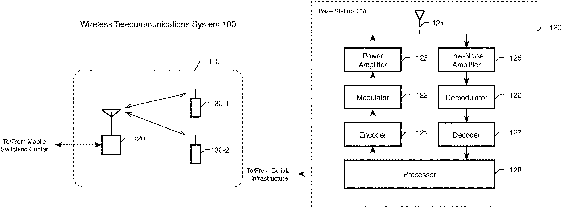
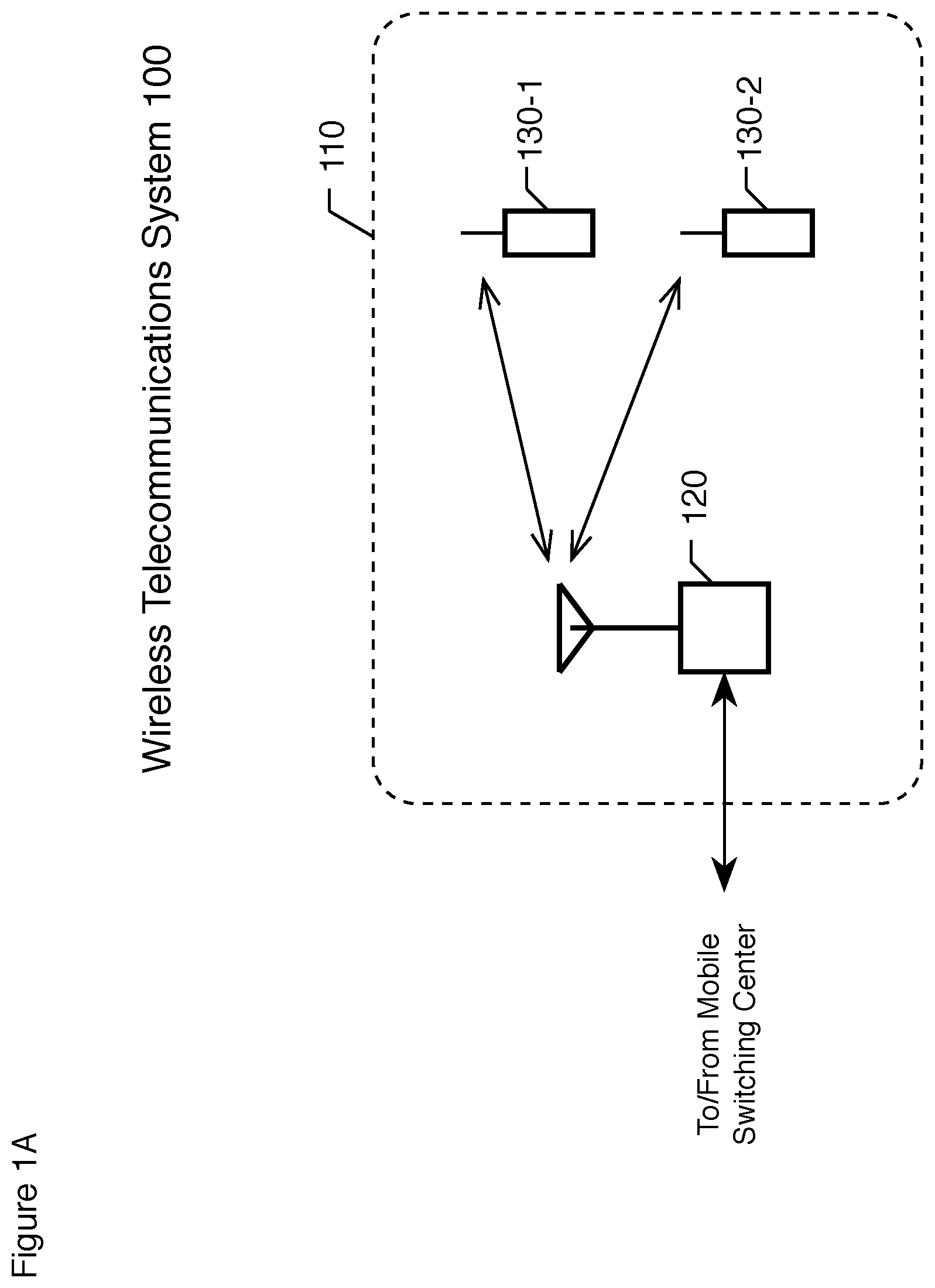
FIG. 1A depicts a block diagram of the salient components of wireless telecommunications system 100 in accordance with the illustrative embodiment of the present invention.
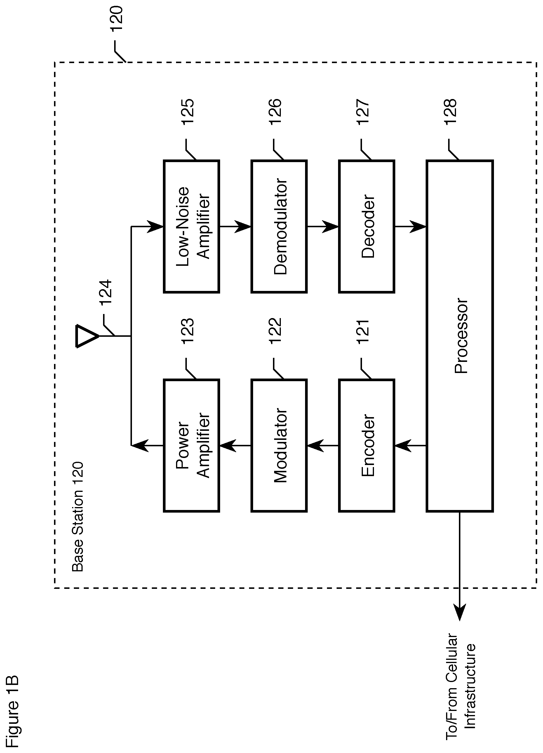
FIG. 1B depicts a block diagram of the salient components of base station 120 in accordance with the illustrative embodiment of the present invention.
FIG. 1C depicts a block diagram of the salient components of wireless terminal 130-a, wherein a.di-elect cons.{1, 2}, in accordance with the illustrative embodiment of the present invention.
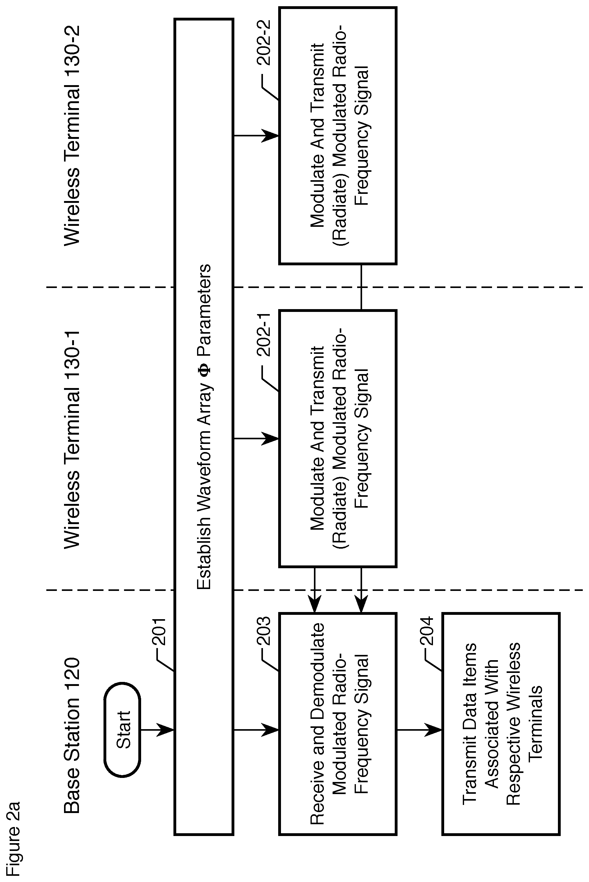
FIG. 2a depicts a flowchart of the salient tasks performed by base station 120, wireless terminal 130-1, and wireless terminal 130-2 in accordance with the illustrative embodiment of the present invention.
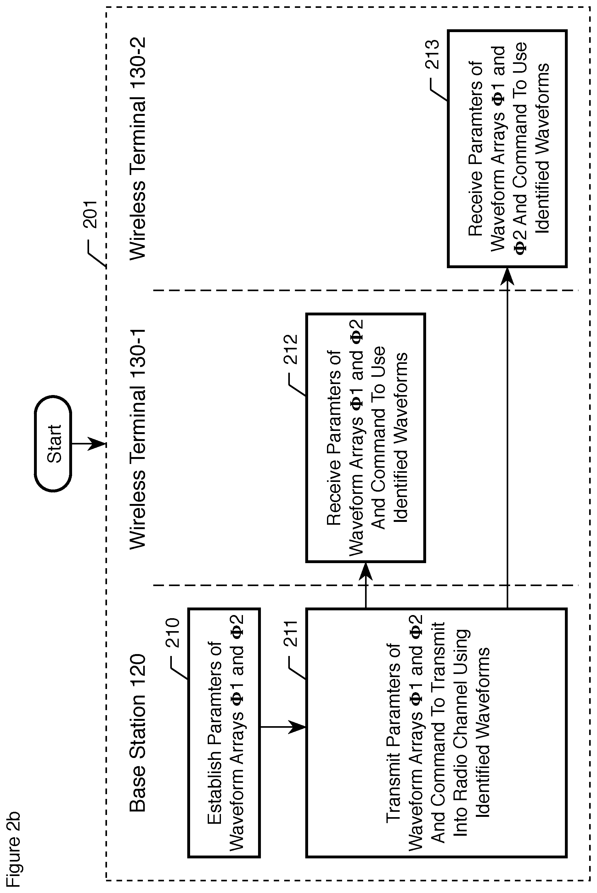
FIG. 2b depicts a flowchart of the salient tasks performed by base station 120, wireless terminal 130-1, and wireless terminal 130-2 in the performance of task 201.
FIG. 3 depicts a waveform array .PHI.1 is based on M1 orthogonal M1-ary stepped-pulse waveforms.
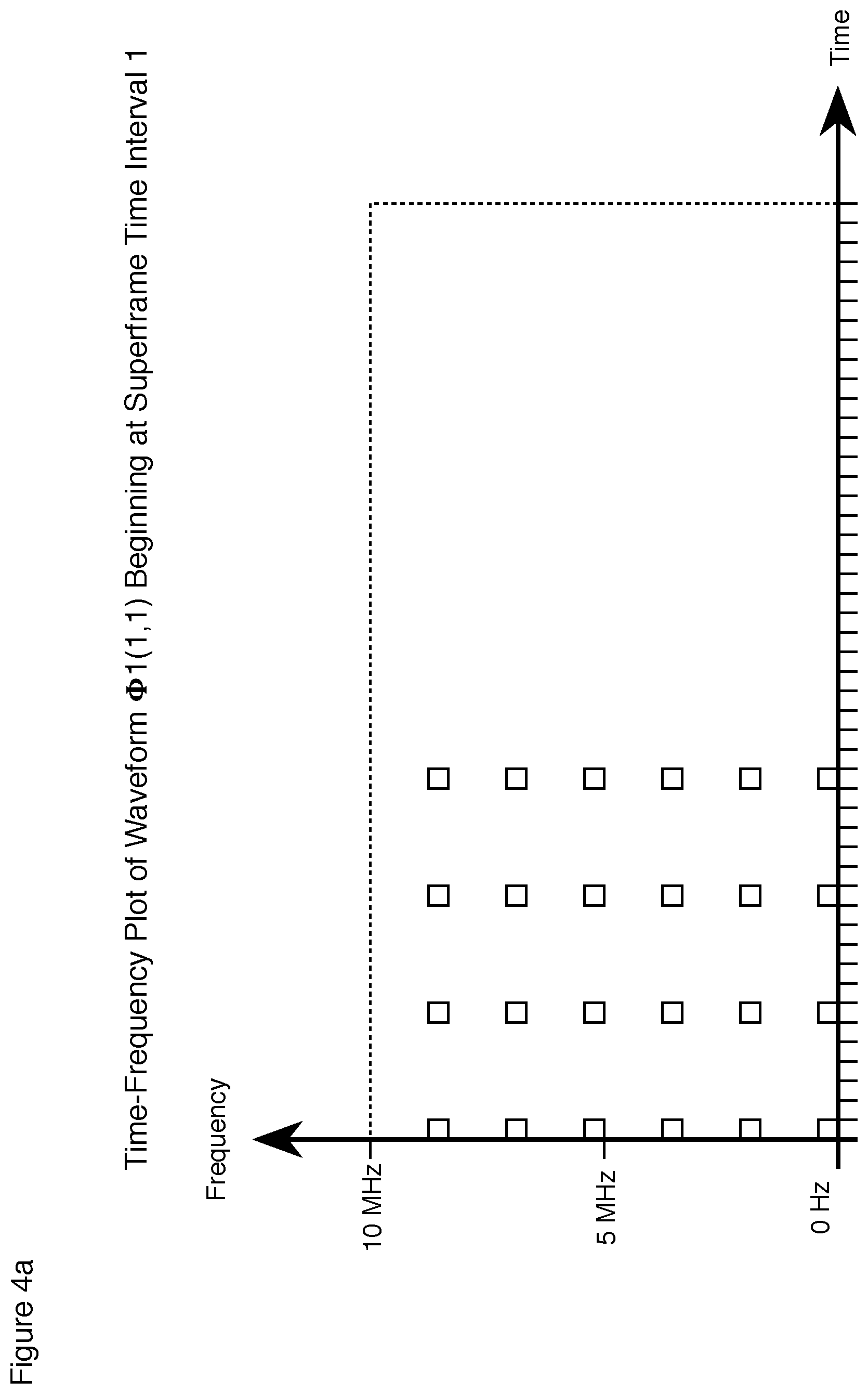
FIG. 4a depicts a plot of where the energy associated with waveform .phi.1(1,1) of waveform array .PHI.1(M1=6, N1=4) beginning at superframe time interval 1 is deposited into a 10 MHz radio channel.
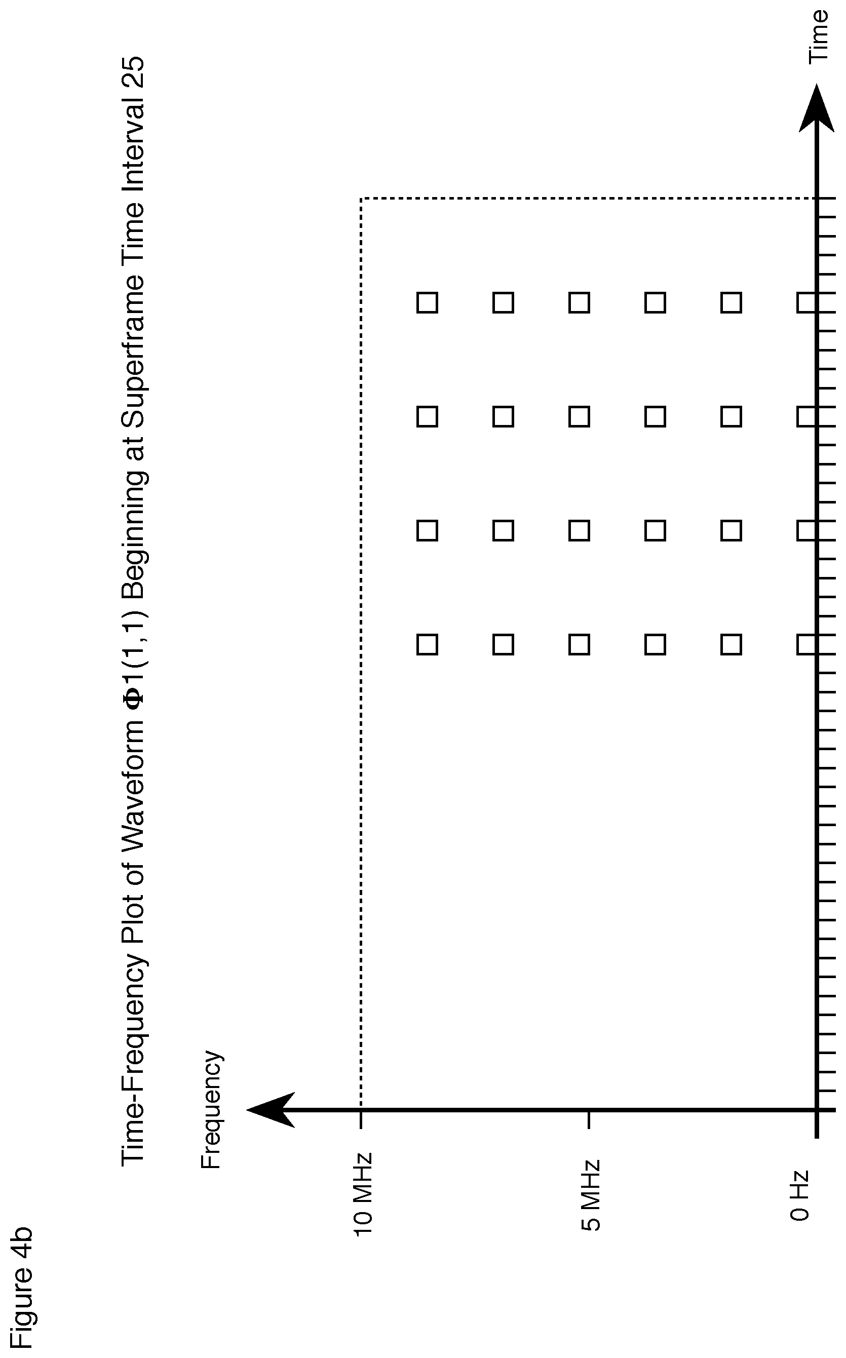
FIG. 4b depicts a plot of where the energy associated with waveform .phi.1(1,1) of waveform array .PHI.1(M1=6, N1=4) beginning at superframe time interval 25 is deposited into a 10 MHz radio channel.
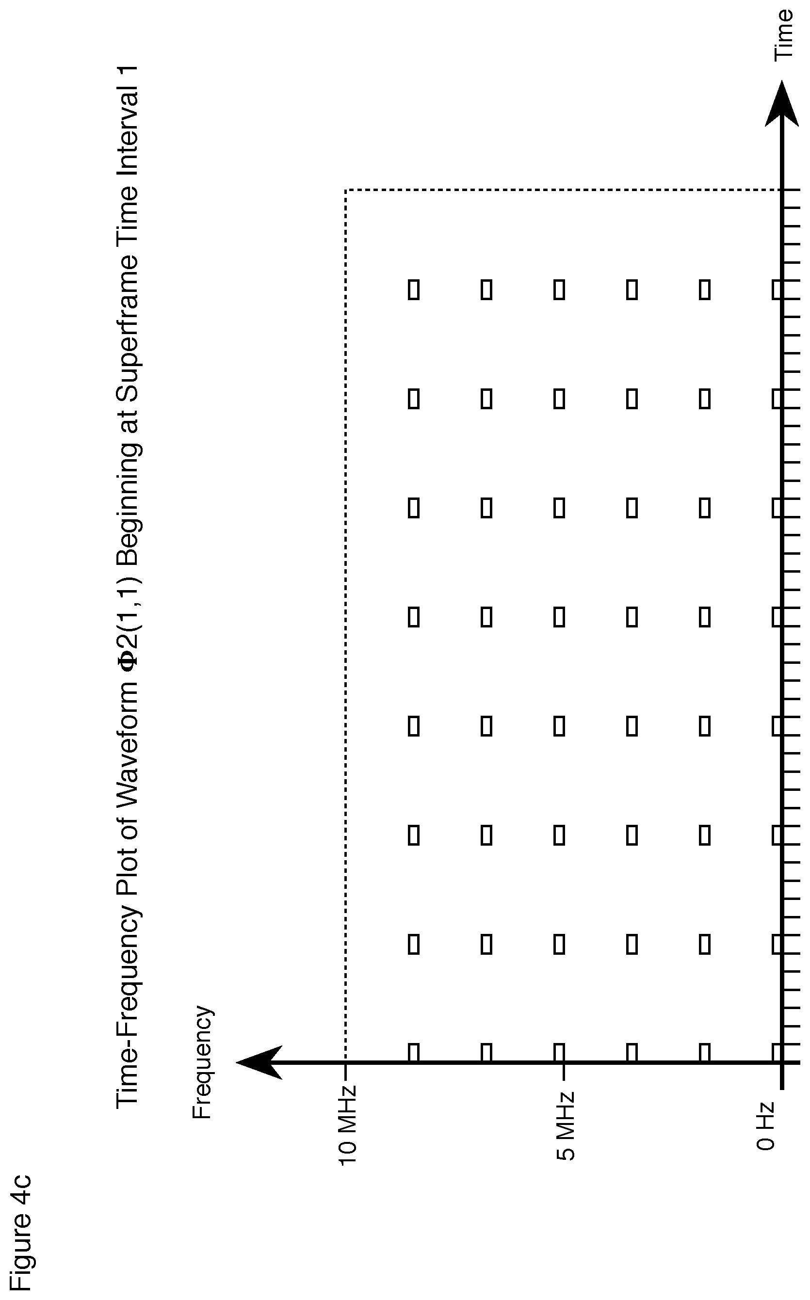
FIG. 4c depicts a plot of where the energy associated with waveform .phi.2(1,1) of waveform array .PHI.2 (M2=6, N2=8) beginning at superframe time interval 1 is deposited into a 10 MHz radio channel.
FIG. 5a depicts a plot of where the energy associated with all of the waveforms from waveform arrays .PHI.1 assigned to base station 130-1 is deposited beginning at superframe time interval 1.
FIG. 5b depicts a plot of where the energy associated with all of the waveforms from waveform arrays .PHI.1 assigned to base station 130-1 is deposited beginning at superframe time interval 25.
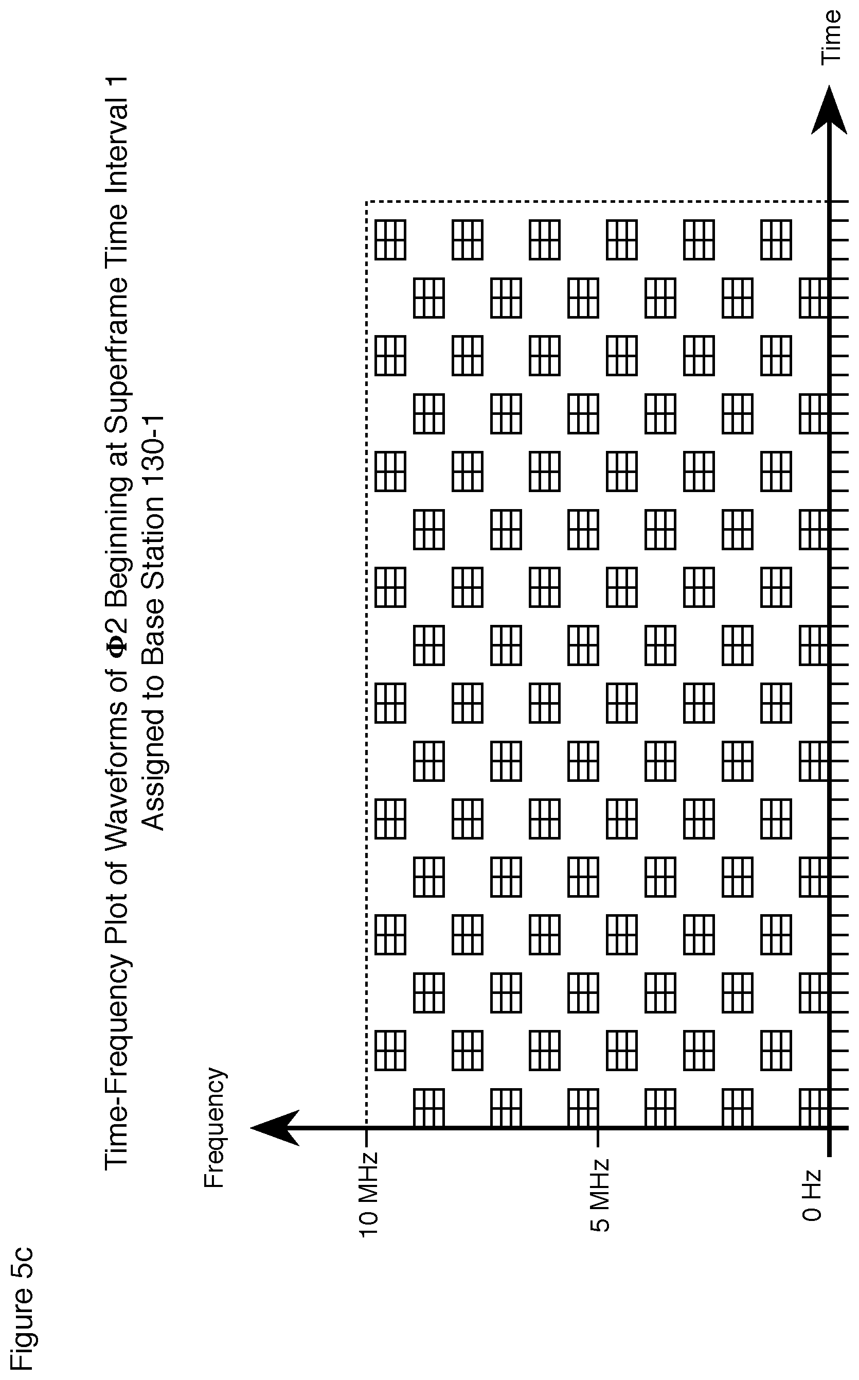
FIG. 5c depicts a plot of where the energy associated with all of the waveforms from waveform arrays .PHI.2 assigned to base station 130-1 is deposited beginning at superframe time interval 1.
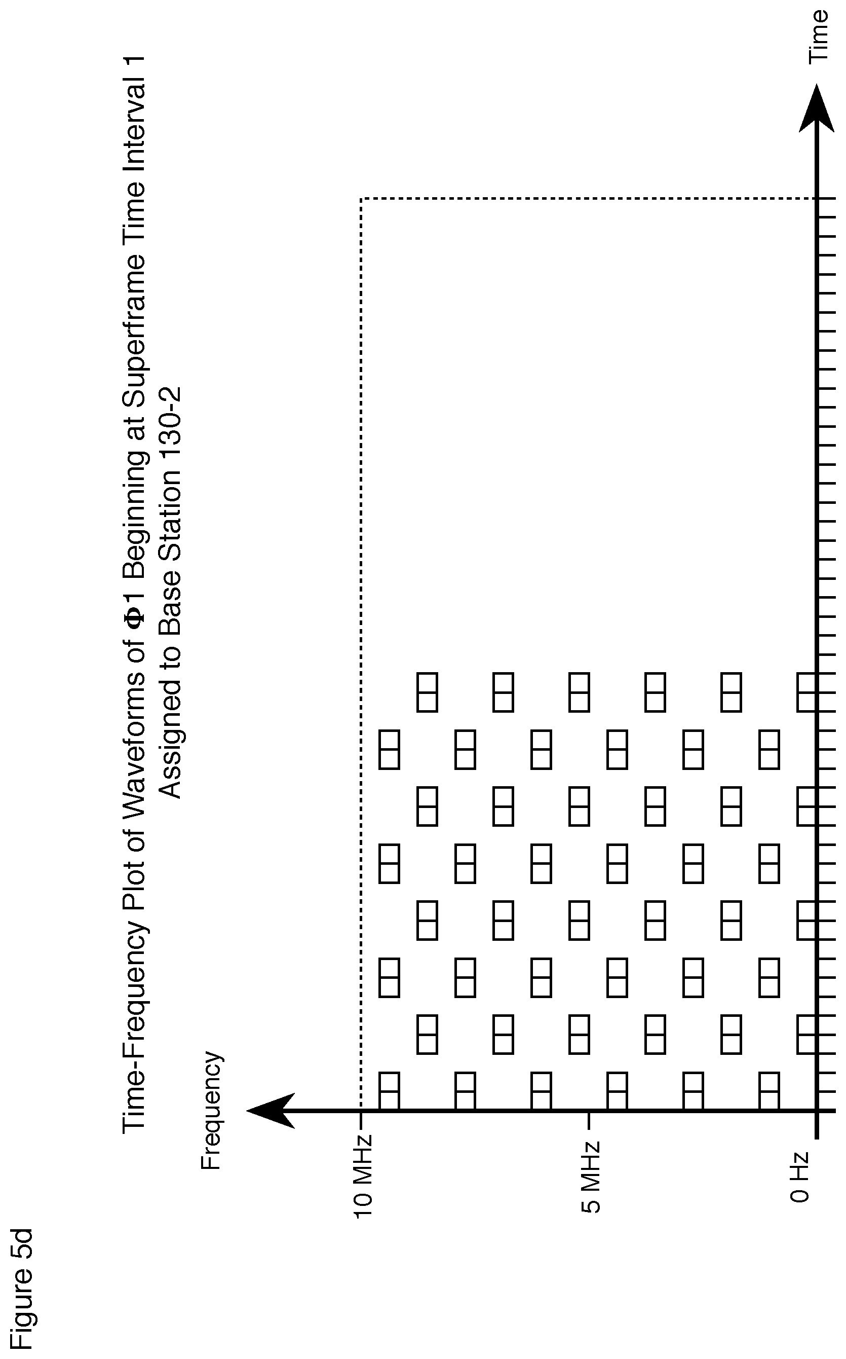
FIG. 5d depicts a plot of where the energy associated with all of the waveforms from waveform arrays .PHI.1 assigned to base station 130-2 is deposited beginning at superframe time interval 1.
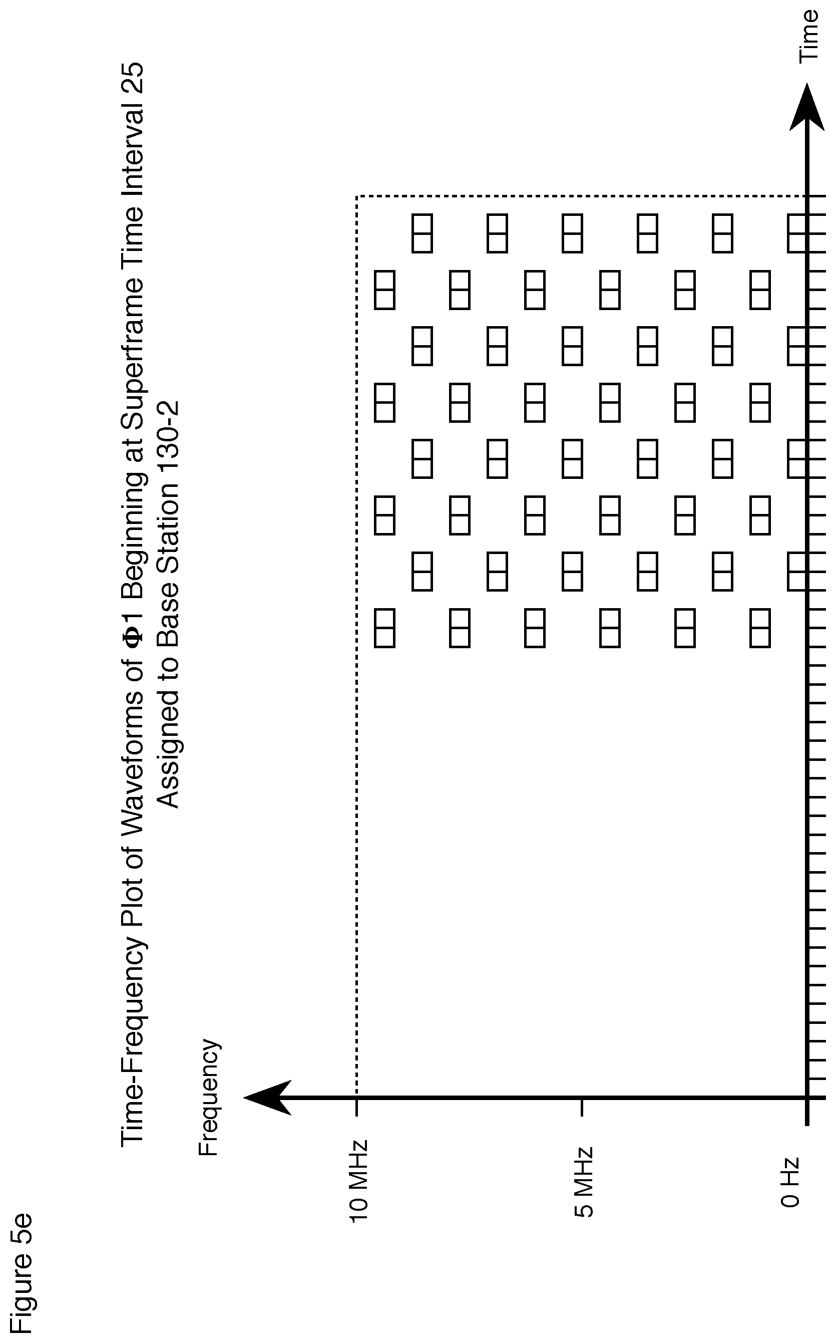
FIG. 5e depicts a plot of where the energy associated with all of the waveforms from waveform arrays .PHI.1 assigned to base station 130-2 is deposited beginning at superframe time interval 25.
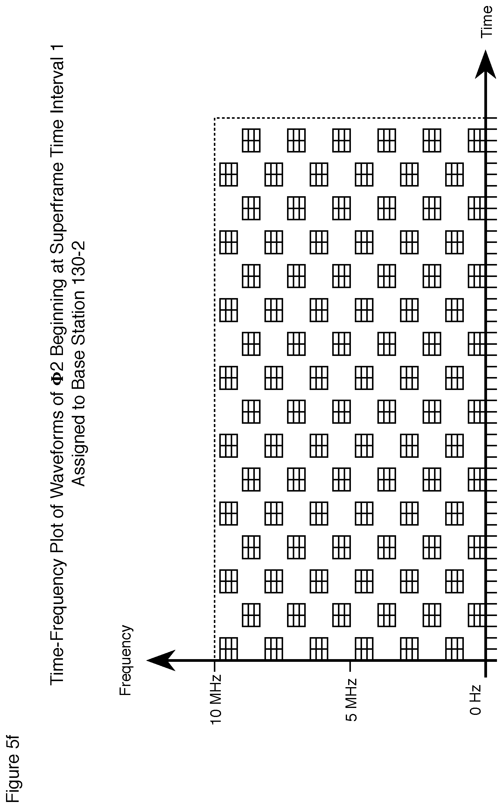
FIG. 5f depicts a plot of where the energy associated with all of the waveforms from waveform arrays .PHI.2 assigned to base station 130-2 is deposited beginning at superframe time interval 1.
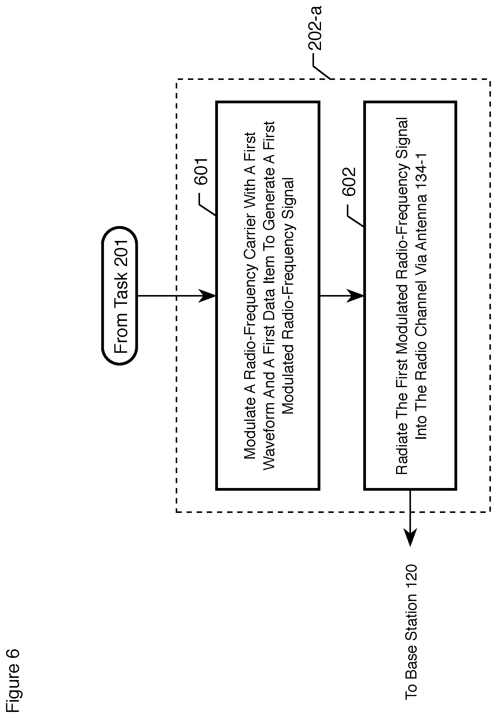
FIG. 6 depicts a flowchart of the salient tasks associated with task 202-a, wherein a.di-elect cons.{1, 2}, in accordance with the illustrative embodiment of the present invention.
DETAILED DESCRIPTION
FIG. 1A depicts a block diagram of the salient components of wireless telecommunications system 100 in accordance with the illustrative embodiment of the present invention. Wireless telecommunications system 100 comprises: base station 120, wireless terminal 130-1, and wireless terminal 130-2, all of which are situated in geographic region 110.
In accordance with the illustrative embodiment, base station 120 provides bi-directional wireless telecommunications service to wireless terminal 130-1 and wireless terminal 130-2.
In accordance with the illustrative embodiment, base station 120 provides telecommunications service by exchanging "data items" with wireless terminal 130-1 and wireless terminal 130-2, which data items represent sound, images, video, data, and signaling. It will be clear to those skilled in the art how to make and use base station 120, wireless terminal 130, and wireless terminal 130-2 so that they can de-construct sound, images, video, data, and signaling into data items, and it will be clear to those skilled in the art how to make and use base station 120, wireless terminal 130, and wireless terminal 130-2 so that they can re-construct sound, images, video, data, and signaling from those data items.
In accordance with the illustrative embodiment, each data item is represented by a complex number that corresponds to one symbol in a 16 quadrature-amplitude ("16 QAM") signal constellation modulation scheme. It will be clear to those skilled in the art, however, after reading this disclosure, how to make and use alternative embodiments of the present invention in which each data item corresponds to a symbol in any digital modulation scheme (e.g., frequency-shift keying, amplitude-shift keying, phase-shift keying, etc.).
In accordance with the illustrative embodiment, wireless telecommunications system 100 comprises one base station and two wireless terminals, but it will be clear to those skilled in the art, after reading this disclosure, how to make and use alternative embodiments of the present invention that comprise any number of base stations and any number of wireless terminals. Furthermore, it will be clear to those skilled in the art how to partition the radio spectrum in an area into radio channels and to assign those channels to the base stations.
In accordance with the illustrative embodiment, base station 120 is stationary and terrestrial, but it will be clear to those skilled in the art, after reading this disclosure, how to make and use alternative embodiments of the present invention in which each base station 120 is mobile or airborne, or mobile and airborne.
In accordance with the illustrative embodiment, wireless terminal 130-1 and wireless terminal 130-2 are mobile, but it will be clear to those skilled in the art, after reading this disclosure, how to make and use alternative embodiments of the present invention in which each wireless terminal is either mobile or stationary.
In accordance with the illustrative embodiment, geographic region 110 comprises natural and man-made radio-frequency objects (not shown) that reflect, refract, and diffract the carrier signals that propagate between base station 120 and wireless terminal 130-1 and wireless terminal 130-2. Furthermore, some of the radio-frequency objects are stationary (e.g., trees, hills, buildings, etc.) and some are mobile (e.g., trucks, ships, airplanes, etc.).
In accordance with the illustrative embodiment, the parameters that characterize the signal-path impairments in the radio channel between base station 120 and wireless terminal 130-1 and wireless terminal 130-2 are dynamic (i.e., change with respect to time). It will be clear to those skilled in the art, after reading this disclosure, how to make and use embodiments of the present invention in which the characteristics of the radio channel and the nature of the signal-path impairments are static (i.e., do not change with respect to time).
In accordance with the illustrative embodiment, base station 120 and wireless terminal 130-1 and wireless terminal 130-2 exchange modulated radio-frequency carrier signals in a radio channel that is B=10 MHz wide. It will be clear to those skilled in the art, however, after reading this disclosure, how to make and use alternative embodiments of the present invention in which the radio channel has a different bandwidth (e.g., 2.5 MHz, 5.0 MHz, 12.5 MHz, 15 MHz, 20 MHz, 40 MHz, 80 MHz, etc.).
FIG. 1B depicts a block diagram of the salient components of base station 120 in accordance with the illustrative embodiment of the present invention. Base station 120 comprises: encoder 121, modulator 122, power amplifier 123, and antenna 124, low-noise amplifier 125, demodulator 126, decoder 127, and processor 128.
Encoder 121 comprises the hardware and software necessary to compress, encrypt, and add forward error correction to the data items to be transmitted to wireless terminal 130-1 and wireless terminal 130-2. It will be clear to those skilled in the art how to make and use encoder 121.
Modulator 122 comprises the hardware and software necessary to modulate a radio-frequency carrier signal with the data items from encoder 121 to generate a modulated radio-frequency carrier signal. The construction and operation of modulator 122 is described in detail herein and in the accompanying figures.
Power amplifier 123 comprises the hardware necessary to increase the power of the modulated radio-frequency carrier signal for transmission via antenna 124. It will be clear to those skilled in the art how to make and use power amplifier 123.
Antenna 124 comprises the hardware necessary to facilitate the radiation of the modulated radio-frequency carrier signal wirelessly through space to wireless terminal 130-1 and wireless terminal 130-2. It will be clear to those skilled in the art how to make and use antenna 124.
Low-Noise amplifier 125 comprises the hardware necessary to increase the power of the modulated radio-frequency carrier signal received via antenna 124. It will be clear to those skilled in the art how to make and use low-noise amplifier 125.
Demodulator 126 comprises the hardware and software necessary to: i. demodulate the modulated radio-frequency carrier signal received by antenna 124, which is the sum of a first modulated radio-frequency carrier signal transmitted by wireless terminal 130-1 and a second modulated radio-frequency carrier signal transmitted by wireless terminal 130-2, and ii. recover one or more data items transmitted by wireless terminal 130-1 that are embodied in the modulated radio-frequency carrier signal and to associate those data items with wireless terminal 130-1, and iii. recover one or more data items transmitted by wireless terminal 130-2 that are embodied in the modulated radio-frequency carrier signal and to associate those data items with wireless terminal 130-2. It will be clear to those skilled in the art, after reading this disclosure, how to make and use demodulator 126.
Decoder 127 comprises the hardware and software necessary to decompress, decrypt, and correct the data items transmitted by wireless terminal 130-1 and wireless terminal 130-2. It will be clear to those skilled in the art how to make and use decoder 127.
Processor 128 comprises the hardware and software necessary to operate base station 120 and to interface with the cellular infrastructure (not shown in FIG. 1B). It will be clear to those skilled in the art, after reading this disclosure, how to make and use processor 128.
FIG. 1C depicts a block diagram of the salient components of wireless terminal 130-a, wherein a.di-elect cons.{1, 2}, in accordance with the illustrative embodiment of the present invention. Wireless terminal 130-a comprises: encoder 131-a, modulator 132-a, power amplifier 133-a, and antenna 134-a, low-noise amplifier 135-a, demodulator 136-a, decoder 137-a, processor 138-a, and user interface 139-a.
Encoder 131-a comprises the hardware and software necessary to compress, encrypt, and add forward error correction to the data items to be transmitted to base station 120. It will be clear to those skilled in the art how to make and use encoder 131-a.
Modulator 132-a comprises the hardware and software necessary to modulate a radio-frequency carrier signal with the data items from encoder 131-a to generate a modulated radio-frequency carrier signal. The construction and operation of modulator 132-a is described in detail herein and in the accompanying figures.
Power amplifier 133-a comprises the hardware necessary to increase the power of the modulated radio-frequency carrier signal for transmission via antenna 134-a. It will be clear to those skilled in the art how to make and use power amplifier 133-a.
Antenna 134-a comprises the hardware necessary to facilitate the radiation of the modulated radio-frequency carrier signal wirelessly through space to base station 120. It will be clear to those skilled in the art how to make and use antenna 134-a.
Low-Noise amplifier 135-a comprises the hardware necessary to increase the power of the modulated radio-frequency carrier signals received via antenna 134-a. It will be clear to those skilled in the art how to make and use low-noise amplifier 135-a.
Demodulator 136-a comprises the hardware and software necessary to demodulate a modulated radio-frequency carrier signal transmitted by base station 120 to recover the data items transmitted by base station 120. It will be clear to those skilled in the art, after reading this disclosure, how to make and use demodulator 136-a.
Decoder 137-a comprises the hardware and software necessary to decompress, decrypt, and correct the data items transmitted by base station 120. It will be clear to those skilled in the art how to make and use decoder 137-a.
Processor 138-a comprises the hardware and software necessary to operate wireless terminal 130-a and to interface with user interface 139-a. It will be clear to those skilled in the art, after reading this disclosure, how to make and use processor 138-a.
User interface 139-a comprises the hardware and software necessary to enable a user (not shown) to interact with wireless terminal 130-a. It will be clear to those skilled in the art how to make and use user interface 139-a.
FIG. 2a depicts a flowchart of the salient tasks performed by base station 120, wireless terminal 130-1, and wireless terminal 130-2 in accordance with the illustrative embodiment of the present invention.
At task 201, base station 120, wireless terminal 130-1, and wireless terminal 130-2 establish the parameters of two non-identical waveform arrays--waveform arrays .PHI.1 and .PHI.2--with which they will communicate. In accordance with the illustrative embodiment, base station 120, wireless terminal 130-1, and wireless terminal 130-2 establish the parameters of two non-identical waveforms arrays but it will be clear to those skilled in the art, after reading this disclosure, how to make and use alternative embodiments of the present invention that establish the parameters of any number (e.g., three, four, six, eight, twelve, sixteen, thirty-two, sixty-four, etc.) of non-identical waveform arrays. Task 201 is described in detail below and in the accompanying figures.
At task 202, wireless terminal 130-1 and wireless terminal 130-2 each transmit (radiate) a modulated radio-frequency carrier signal in a radio channel to base station 120 in accordance with the parameters of waveform arrays .PHI.1 and .PHI.2. Task 202 is described in detail below and in the accompanying figures.
At task 203, base station 120 receives a radio-frequency signal from the radio channel that is a sum of: 1. the modulated radio-frequency carrier signal radiated by wireless terminal 130-1, plus 2. the multipath images (if any) of the modulated radio-frequency carrier signal radiated by wireless terminal 130-1, plus 3. the modulated radio-frequency carrier signal radiated by wireless terminal 130-2, plus 4. the multipath images (if any) of the modulated radio-frequency carrier signal radiated by wireless terminal 130-2, plus 5. noise. As part of task 203, base station 120 demodulates and decodes the radio-frequency signal to recover one or more data items transmitted by wireless terminal 130-1 (and to associate those data items with wireless terminal 130-1) and one or more data items transmitted by wireless terminal 130-2 (and to associate those data items with wireless terminal 130-2). It will be clear to those skilled in the art, after reading this disclosure, how to make and use base station 120 to be able to perform task 230.
At task 204, base station 120 transmits one or more data items associated with wireless terminal 130-1 and one or more data items associated with wireless terminal 130-2 to the cellular infrastructure (e.g., a mobile switching center, etc.), which is not shown in FIG. 1B.
FIG. 2b depicts a flowchart of the salient tasks performed by base station 120, wireless terminal 130-1, and wireless terminal 130-2 in the performance of task 201. As part of task 120, the parameters of waveform arrays .PHI.1 and .PHI.2are chosen to: i. mitigate infra-symbol interference caused by Doppler-shift and multipath interference in the radio channel, and ii. enable simultaneous multiple access by both wireless terminal 130-1 and wireless terminal 130-2 to base station 120, and iii. enable wireless terminal 130-1 to transmit waveforms of waveform arrays .PHI.1 and .PHI.2 into the radio channel at the same time (i.e., concurrently) while wireless terminal 130-2 transmits different waveforms of waveform arrays .PHI.1 and .PHI.2 into the same radio channel.
At task 210, and as is described in detail below, each waveform array .PHI.j is characterized by two parameters Mj and Nj, wherein Mj and Nj are a positive integers greater than one and j.di-elect cons.{1, 2} (i.e., waveform array .PHI.1 is characterized by parameters M1 and N1 and waveform array .PHI.2 is characterized by parameters M2 and N2).
In accordance with the first illustrative embodiment, M1=M2=6, N1=4, and N2=8 (i.e., M1=M2 and N1.noteq.N2). In accordance with the second illustrative embodiment, M1=16, M2=32, and N1=N2=8 (i.e., M1.noteq.M2 and N1=N2). In accordance with the third illustrative embodiment, M1=16, M2=32, N1=32, and N2=8 (i.e., M1.noteq.M2 and N1.noteq.N2). In all three illustrative embodiments, M1N1.noteq.M2N2.
It will be clear to those skilled in the art, after reading this disclosure, how to make and use alternative embodiments of the present invention with any combination of values of M1, M2, N1, and N2. Furthermore, it will be clear to those skilled in the art, after reading this disclosure, that embodiments of the present invention are typically simplified and more efficient by making M2 an integral multiple of M1 (e.g., 2.times., 3.times., 4.times., 5.times., 6.times., 8.times., 12.times., 16.times., 32.times., 64.times., 128.times., etc.). And still furthermore, it will be clear to those skilled in the art, after reading this disclosure, that embodiments of the present invention are typically simplified and more efficient by making N2 an integral multiple of N1 (e.g., 2.times., 3.times., 4.times., 5.times., 6.times., 8.times., 12.times., 16.times., 32.times., 64.times., 128.times., etc.).
In accordance with the illustrative embodiment, the parameters of waveform arrays .PHI.1 and .PHI.2 are established once when base station 120, wireless terminal 130-1, and wireless terminal 130-2 first establish communication, but it will be clear to those skilled in the art, after reading this disclosure, how to make and use alternative embodiments of the present invention in which base station 120, wireless terminal 130-1, and wireless terminal 130-2 periodically or sporadically re-establish the parameters of waveform array .PHI.1 or waveform array .PHI.2 or waveform arrays .PHI.1 and .PHI.2. For example and without limitation, base station 120, wireless terminal 130-1, and wireless terminal 130-2 can re-establish the parameters of waveform arrays .PHI.1 and .PHI.2 when: i. the traits of the signal path from change, or ii. the type of data represented by the data items changes, or iii. the latency tolerance of the data items changes, or iv. any combination of i, ii, and iii.
As is described in detail below, waveform arrays .PHI.1 and .PHI.2 comprise waveforms that convey data items from wireless terminal 130-1 or wireless terminal 130-2 to base station 120. In accordance with the illustrative embodiment, wireless terminal 130-1 and wireless terminal 130-2 convey low-latency tolerant data items using waveform array .PHI.1 and high-latency tolerant data items using waveform array .PHI.2. It will be clear to those skilled in the art, after reading this disclosure, how to make and use alternative embodiments of the present invention in which wireless terminal 130-1 and wireless terminal 130-2 use the waveforms in different waveform arrays for: i. different conditions of the signal path from wireless terminal 130-1 or wireless terminal 130-2 to base station 120, or ii. different types of data items, or iii. different latency tolerance of the data items, or iv. any combination of i, ii, and iii.
Basic Waveforms--
Waveform array .PHI.j is based on an extension of Mj basic waveforms bj(1), . . . , bj(mj), . . . , bj(Mj) that are orthogonal in Mj-dimensional vector space, where Mj is a positive integer greater than 1, and mj is a positive integer in the range mj.di-elect cons.{1, . . . , Mj}.
In accordance with all of the illustrative embodiments, basic waveform bj(mj) is waveform mj of a Mj-ary stepped-pulse waveform scheme, as depicted in FIG. 3. In accordance with all of the illustrative embodiments, each pulse is a band-limited raised-cosine pulse but it will be clear to those skilled in the art, after reading this disclosure, how to make and use alternative embodiments of the present invention in which each pulse has a different shape.
Each pulse in basic waveform bj(mj) is band-limited, and, therefore, the duration of each pulse is 1/B seconds, wherein B is the bandwidth of the channel. Furthermore, the centers of adjacent pulses are separated by 1/B seconds. And still furthermore, the total duration of each basic waveform bj(mj) is Mj/B seconds.
Although all of the illustrative embodiments uses stepped-pulse waveforms as the basic waveforms, it will be clear to those skilled in the art, however, after reading this disclosure, how to make and use alternative embodiments of the present invention in which waveform array .PHI.j is based on any set of Mj orthogonal waveforms, bj(1), . . . , bj(Mj).
Structure of Waveform Array .PHI.--
Waveform array 1j comprises MjNj waveforms that are orthogonal in MjNj-dimensional vector space. The MjNj waveforms of waveform array .PHI.j are denoted .phi.j(1,1), . . . , .phi.j(mj,nj), . . . , .phi.j(Mj,Nj), where nj is a positive integer in the range nj.di-elect cons.{1, . . . , Nj}.
Each waveform .phi.j(mj,nj) is the sum of Nj waveforms yj(mj,nj,1), . . . , yj(mj,nj,pj), . . . , yj(mj,nj,Nj).
Each waveform .phi.j(mj,nj) is identically partitioned into Nj time slots 1, . . . , pj, . . . , Nj, where pj is a positive integer in the range pj.di-elect cons.{1, . . . , Nj}. Waveform yj(mj,nj,pj) occupies time slot pj in waveform .phi.j(mj,pj) and equals: yj(mj,nj,pj)=bj(mj)u(nj,pj) (Eq. 1) wherein u(nj,pj) is a phasor that equals: u(nj,pj)=exp(2.pi.(nj-1)(pj-1)i/Nj) (Eq. 2) The duration of waveform y(mj,nj,pj) defines the duration of time slot pj.
The MjNj waveforms of waveform array .PHI.j partition the time-frequency space of the modulated radio-frequency carrier signal into 1/B second-long "time intervals" and MjNj "frequency sub-bands." Each waveform array .PHI.j constitutes a "frame" of MjNj time intervals, and the least common multiple of MjNj for all j (e.g., the LCM(M1N1, M2N2) for j.di-elect cons.{1, 2}) constitutes a "superframe" of time intervals. The temporal start of each waveform is specified relative to the first time interval in the superframe.
A salient characteristic of the illustrative embodiment is that each waveform .PHI.j(mj,nj) in waveform array .PHI.j deposits energy into: i. unique time-frequency portions the radio channel, and ii. 1/Mjj.sup.th of the radio channel during the frame of waveform array .PHI.j. This is illustrated in FIGS. 4a, 4b, and 4c for waveform array .PHI.1(M1=6, N1=4) and waveform array .PHI.2 (M2=6, N2=8).
For example, FIG. 4a depicts a plot of where the energy associated with waveform .phi.1(1,1) of waveform array .PHI.1(M1=6, N1=4) beginning at superframe time interval 1 is deposited into a 10 MHz radio channel. In FIG. 4a the radio channel is depicted as divided into twenty-four (M1N1=24) 416.66 KHz frequency sub-bands (B=10 MHz/M1N1=24) and forty-eight [LCM(M1N1, M2N2)=24] 0.1 microsecond (1/B=10 MHz) time intervals. In FIG. 4a, it can be seen that energy is deposited only in time intervals 1, 7, 13, and 19 and only in the frequency sub-bands 0-0.416 MHz, 1.666-2.083 MHz, 3.333-3.750 MHz, 5.000-5.417 MHz, 6.666-7.083 MHz, and 8.333-8.750 MHz in the channel.
FIG. 4b depicts a plot of where the energy associated with waveform .phi.1(1,1) of waveform array .PHI.1(M1=6, N1=4) beginning at superframe time interval 25 is deposited into a 10 MHz radio channel. In FIG. 4a the radio channel is depicted as divided into twenty-four (M1N1=24) 416.66 KHz frequency sub-bands (B=10 MHz/M1N1=24) and forty-eight [LCM(M1N1, M2N2)=24] 0.1 microsecond (1/B=10 MHz) time intervals. In FIG. 4b, it can be seen that energy is deposited only in time intervals 25, 31, 37, and 43 and only in the frequency sub-bands 0-0.416 MHz, 1.666-2.083 MHz, 3.333-3.750 MHz, 5.000-5.417 MHz, 6.666-7.083 MHz, and 8.333-8.750 MHz in the channel.
Similarly, FIG. 4c depicts a plot of where the energy associated with waveform .phi.2(1,1) of waveform array .PHI.2 (M2=6, N2=8) beginning at superframe time interval 1 is deposited into a 10 MHz radio channel. In FIG. 4a the radio channel is depicted as divided into twenty-four (M1N1=24) 416.66 KHz frequency sub-bands (B=10 MHz/M1N1=24) and forty-eight [LCM(M1N1, M2N2)=24] 0.1 microsecond (1/B=10 MHz) time intervals. In FIG. 4c, it can be seen that energy is deposited only in time intervals 1, 7, 13, 19, 25, 31, 37, and 43 and only in the frequency sub-bands 0-0.208 MHz, 1.666-1.875 MHz, 3.333-3.541 MHz, 5.000-5.208 MHz, 6.666-6.875 MHz, and 8.333-8.541 MHz in the channel.
It will be clear to those skilled in the art how to determine when and where any given waveform .phi.j(mj,nj) will deposit energy into a radio channel using Fourier analysis in well-known fashion.
In accordance with the illustrative embodiment, base station 120 selects individual waveforms from waveform arrays .PHI.1 and .PHI.2 to convey data items from wireless terminal 130-1 and wireless terminal 130-2, and selects those waveforms so that: I. no two waveforms overlap the time-frequency space of the modulated radio-frequency carrier signal (to prevent inter-symbol interference), and II. all of the time-frequency space of the modulated radio-frequency carrier signal has energy deposited into it (to maximize spectral efficiency), and III. waveforms from waveform array .PHI.1 convey data items with low-latency tolerance and waveforms from waveform array .PHI.2 convey data items with high-latency tolerance. To accomplish this, base station 120 instructs wireless terminal 130-1 and wireless terminal 130-2 how to transmit waveforms from waveform array .PHI.1 and waveforms from waveform array .PHI.2 into the same channel at the same time with satisfactory guard waveforms (i.e., how to transmit waveforms from waveform array .PHI.1 and waveforms from waveform array .PHI.2 so that they: 1. overlap in the 4.8 microsecond superframe "time space" of the radio channel, and 2. overlap in the 10 MHz "frequency space" of the radio channel, and 3. do not overlap in the "time-frequency space" of the radio channel.
For example, FIGS. 5a, 5b, 5c, 5d, 5e, and 5f depict waveforms in which waveforms from waveform arrays .PHI.1(M1=6, N1=4) and .PHI.2(M2=6, N2=8) are either exclusively: 1. assigned to base station 130-1 to transmit data items to base station 120, or 2. assigned to base station 130-2 to transmit data items to base station 120, or 3. reserved as guard waveforms (and not transmitted by either base station 130-1 or base station 130-2.
Base station 130-1 is assigned four waveforms from waveform array .PHI.1 beginning at superframe time interval 1 and superframe time interval 25, as shown in Table 1 and as depicted in FIGS. 5a and 5b, respectively.
TABLE-US-00001 TABLE 1 Waveforms from Waveform Array .PHI.1 Assigned to Base Station 130-1 Conveying Beginning Waveform Superframe Time Interval .phi.1(1,1) 1, 25 .phi.1(1,2) 1, 25 .phi.1(4,3) 1, 25 .phi.1(5,3) 1, 25
Base station 130-1 is also assigned twelve waveforms from waveform array .PHI.2 beginning at superframe time interval 1, as shown in Table 2 and as depicted in FIG. 5c.
TABLE-US-00002 TABLE 2 Waveforms from Waveform Array .PHI.2 Assigned to Base Station 130-1 Conveying Beginning Waveform Superframe Time Interval .phi.2(1,1) 1 .phi.2(1,2) 1 .phi.2(1,3) 1 .phi.2(2,1) 1 .phi.2(2,3) 1 .phi.2(2,4) 1 .phi.2(4,5) 1 .phi.2(4,6) 1 .phi.2(4,7) 1 .phi.2(5,5) 1 .phi.2(5,6) 1 .phi.2(5,7) 1
It will be clear to those skilled in the art, after reading this disclosure, that base station 130-1 can transmit (in a single superframe) only those combinations of waveforms assigned to it that do not interfere with each other (i.e., do not put energy into the same "time-frequency space" of the radio channel). Furthermore, it will be clear to those skilled in the art, after reading this disclosure, which combinations of waveforms can be transmitted (in a single superframe) so as to not interfere with each other.
Base station 130-2 is assigned four waveforms from waveform array .PHI.1 beginning at superframe time interval 1 and superframe time interval 25, as shown in Table 3 and as depicted in FIGS. 5d and 5e, respectively.
TABLE-US-00003 TABLE 3 Waveforms from Waveform Array .PHI.1 Assigned to Base Station 130-2 Conveying Beginning Waveform Superframe Time Interval .phi.1(1,3) 1, 25 .phi.1(2,3) 1, 25 .phi.1(4,1) 1, 25 .phi.1(5,1) 1, 25
Base station 130-2 is also assigned twelve waveforms from waveform array .PHI.2 beginning at superframe time interval 1, as shown in Table 4 and as depicted in FIG. 5f.
TABLE-US-00004 TABLE 4 Waveforms from Waveform Array .PHI.2 Assigned to Base Station 130-2 Conveying Beginning Waveform Superframe Time Interval .phi.2(1,5) 1 .phi.2(1,6) 1 .phi.2(1,7) 1 .phi.2(2,5) 1 .phi.2(2,6) 1 .phi.2(2,7) 1 .phi.2(4,1) 1 .phi.2(4,2) 1 .phi.2(4,3) 1 .phi.2(5,1) 1 .phi.2(5,2) 1 .phi.2(5,3) 1
It will be clear to those skilled in the art, after reading this disclosure, that base station 130-1 can transmit (in a single superframe) only those combinations of waveforms assigned to it that do not interfere with each other (i.e., do not put energy into the same "time-frequency space" of the radio channel). Furthermore, it will be clear to those skilled in the art, after reading this disclosure, which combinations of waveforms can be transmitted (in a single superframe) so as to not interfere with each other.
The remaining waveforms--which were not assigned to either base station 130-1 or base station 130-2--are reserved as guard waveforms in order to reduce inter-symbol interference from multi-path images and Doppler shifts.
It will be clear to those skilled in the art, after reading this disclosure, how to make and use alternative embodiments of the present invention that assign any combination of waveforms for conveying data items and any combination of waveforms for use as guard waveforms. Furthermore, it will be clear to those skilled in the art, after reading this disclosure, how to partition the waveforms in waveform array .PHI. among any number of wireless terminals and guard waveforms.
At task 211, base station 120 transmits the waveform array .PHI. parameters to wireless terminal 130-1 and wireless terminal 130-2 along with a command to transmit into the radio channel using the assigned waveforms.
At task 212, wireless terminal 130-1 receives the waveform array .PHI. parameters and the command to use the waveforms assigned to it.
At task 213, wireless terminal 130-2 receives the waveform array .PHI. parameters and the command to use the waveforms assigned to it.
FIG. 6 depicts a flowchart of the salient tasks associated with task 202-a, wherein a.di-elect cons.{1, 2}, in accordance with the illustrative embodiment of the present invention.
At task 1601, wireless terminal 130-a establishes a one-to-one relationship between each data item it will transmit to base station 120 and each waveform .phi.(m,n) in waveform array .PHI. that has been assigned to it. As part of task 1601, wireless terminal 130-a modulates a radio-frequency carrier signal with each waveform assigned to it and the corresponding data item to generate a modulated radio-frequency carrier signal. It will be clear to those skilled in the art, after reading this disclosure, how to make and use embodiments of the present invention that perform task 1601.
At task 1602, the modulated radio-frequency carrier signal is radiated into the radio channel via antenna 134-a for reception by base station 120. It will be clear to those skilled in the art, after reading this disclosure, how to make and use embodiments of the present invention that perform task 1602.
Markman Definitions
Orthogonal--For the purpose of this specification, two waveforms are orthogonal if their inner product is zero over the time interval of interest.
Identical Waveform Arrays--For the purposes of this specification, waveform array .PHI.1(M1, N1) and waveform array .PHI.2(M2, N2) are identical if M1=M2 and N1=N2.
Non-identical Waveform Arrays--For the purposes of this specification, waveform array .PHI.1(M1, N1) and waveform array .PHI.2(M2, N2) are non-identical if they are not identical.
* * * * *
References
D00000
D00001
D00002
D00003
D00004
D00005
D00006
D00007
D00008
D00009
D00010
D00011
D00012
D00013
D00014
D00015
D00016
P00001

XML
uspto.report is an independent third-party trademark research tool that is not affiliated, endorsed, or sponsored by the United States Patent and Trademark Office (USPTO) or any other governmental organization. The information provided by uspto.report is based on publicly available data at the time of writing and is intended for informational purposes only.
While we strive to provide accurate and up-to-date information, we do not guarantee the accuracy, completeness, reliability, or suitability of the information displayed on this site. The use of this site is at your own risk. Any reliance you place on such information is therefore strictly at your own risk.
All official trademark data, including owner information, should be verified by visiting the official USPTO website at www.uspto.gov. This site is not intended to replace professional legal advice and should not be used as a substitute for consulting with a legal professional who is knowledgeable about trademark law.