Housing of vehicle lithium battery-modules
Aimo Boot , et al.
U.S. patent number 10,714,719 [Application Number 15/310,497] was granted by the patent office on 2020-07-14 for housing of vehicle lithium battery-modules. This patent grant is currently assigned to IVECO S.p.A., NICE POWER S.r.l.. The grantee listed for this patent is IVECO S.p.A., NICE POWER S.r.l.. Invention is credited to Marco Aimo Boot, Giorgio Mantovani, Marino Sergi.
| United States Patent | 10,714,719 |
| Aimo Boot , et al. | July 14, 2020 |
Housing of vehicle lithium battery-modules
Abstract
A housing of vehicle lithium battery-modules, each battery-module having an evacuation opening and a parallelepipedal shape, where a plurality of horizontal plates are arranged inside the housing, parallel to each other, alternated with layers of the battery-modules, wherein each one of the horizontal plates is joined to perimetral surfaces of the housing to convey heat towards the external environment, wherein each battery-module is arranged so that the evacuation openings are vertically aligned, and wherein each one of the horizontal plates comprises corresponding openings equipped with appropriate gaskets on both the opposite faces of the horizontal plates, in order to define continuous and gastight evacuation channels between the battery-modules.
| Inventors: | Aimo Boot; Marco (Caselle Torinese, IT), Mantovani; Giorgio (Genoa, IT), Sergi; Marino (Rivalta di Torino, IT) | ||||||||||
|---|---|---|---|---|---|---|---|---|---|---|---|
| Applicant: |
|
||||||||||
| Assignee: | IVECO S.p.A. (Turin,
IT) NICE POWER S.r.l. (Turin, IT) |
||||||||||
| Family ID: | 51230005 | ||||||||||
| Appl. No.: | 15/310,497 | ||||||||||
| Filed: | May 12, 2015 | ||||||||||
| PCT Filed: | May 12, 2015 | ||||||||||
| PCT No.: | PCT/IB2015/053497 | ||||||||||
| 371(c)(1),(2),(4) Date: | November 11, 2016 | ||||||||||
| PCT Pub. No.: | WO2015/173737 | ||||||||||
| PCT Pub. Date: | November 19, 2015 |
Prior Publication Data
| Document Identifier | Publication Date | |
|---|---|---|
| US 20170077471 A1 | Mar 16, 2017 | |
Foreign Application Priority Data
| May 12, 2014 [IT] | MI2014A0854 | |||
| Current U.S. Class: | 1/1 |
| Current CPC Class: | B60L 3/0046 (20130101); B60L 58/26 (20190201); H01M 10/613 (20150401); H01M 2/12 (20130101); H01M 10/6562 (20150401); H01M 2/1077 (20130101); H01M 10/6566 (20150401); H01M 10/6555 (20150401); H01M 10/6556 (20150401); H01M 10/6563 (20150401); H01M 10/6551 (20150401); H01M 10/0525 (20130101); Y02E 60/10 (20130101); H01M 2220/20 (20130101); Y02T 10/70 (20130101) |
| Current International Class: | H01M 2/12 (20060101); B60L 3/00 (20190101); B60L 58/26 (20190101); H01M 10/0525 (20100101); H01M 10/613 (20140101); H01M 10/6562 (20140101); H01M 10/6556 (20140101); H01M 10/6555 (20140101); H01M 2/10 (20060101); H01M 10/6566 (20140101); H01M 10/6563 (20140101); H01M 10/6551 (20140101) |
References Cited [Referenced By]
U.S. Patent Documents
| 2005/0170240 | August 2005 | German et al. |
| 2007/0144804 | June 2007 | Pike |
| 2008/0268316 | October 2008 | Park |
| 2012/0129024 | May 2012 | Marchio et al. |
| 2013/0004822 | January 2013 | Hashimoto |
| 2013/0220716 | August 2013 | Favaretto |
| 2013/0266838 | October 2013 | Borck |
| 2014/0057144 | February 2014 | Yang |
| 2014/0072861 | March 2014 | Nakayama |
| 2626923 | Aug 2013 | EP | |||
| 2738834 | Jun 2014 | EP | |||
| WO 2013/018283 | Feb 2013 | WO | |||
Other References
|
International Search Report for International Application No. PCT/IB2015/053497 dated Sep. 11, 2015, 2 pages. cited by applicant. |
Primary Examiner: Barrow; Amanda J
Attorney, Agent or Firm: RMCK Law Group, PLC
Claims
The invention claimed is:
1. A housing (1) having vehicle battery-modules (M), each vehicle battery-module (M) having a parallelepipedal shape with at least an evacuation through opening (M1) for hot gases, the housing having a parallelepipedal shape having an upper surface (1S), a lower surface (1I) and perimetral surfaces (1F, 1L, 1P) and having a plurality of horizontal plates (PO) arranged inside the housing (1), parallel to each other, alternated in direct physical contact with and between two layers of at least three layers (S1, S2, S3) of the battery-modules (M), wherein each one of said horizontal plates (PO) is joined to said perimetral surfaces (1F, 1L, 1P) to convey the heat towards the external environment, wherein each battery-module (M) is arranged so that said evacuation through openings (M1) of the at least three layers (S1, S2, S3) of the battery-modules (M) are vertically aligned with each other, wherein each one of said horizontal plates (PO) comprises corresponding through openings (2) equipped with appropriate gaskets on both the opposite faces of the horizontal plates (PO) in order to define continuous and gastight vertical evacuation channels defined by cooperation and vertical alignment of the evacuation through openings (M1) of the at least three layers (S1, S2, S3) of the battery-modules (M) and the corresponding through openings (2) of the horizontal plates (PO), and wherein the continuous and gastight vertical evacuation channels are the only evacuation channels present in the housing (1) from the lower surface (1I) through the at least three layers (S1, S2, S3) of battery-modules (M) and intervening horizontal plates (PO).
2. The housing (1) according to claim 1, wherein the evacuation through openings (M1) are parallel to one side of the housing (1).
3. The housing (1) according to claim 1, wherein above said continuous and gastight vertical evacuation channels, a horizontal canalization (G) is arranged and adapted to convey the hot gases from said continuous and gastight vertical evacuation channels, the horizontal canalization (G) having a chimney (C) which makes said horizontal canalization (G) communicate with the external environment, through the upper surface (1S).
4. The housing (1) according to claim 1, wherein said lower surface (1I) comprises further openings, operatively in alignment with and in communication with the evacuation through openings (M1), so as to facilitate gas circulation of the hot gases from a bottom of the housing (1) upwards.
5. The housing (1) according to claim 4, wherein said openings of the lower surface (1I) are surrounded by gaskets (H).
6. The housing (1) according to claim 1, wherein said continuous and gastight vertical evacuation channels between the layers (S1, S2, S3) of battery-modules (M) are open only towards the outside of the housing (1).
7. The housing (1) according to claim 1, wherein, when a respective battery-module (M) is absent, at least one of said continuous and gastight vertical evacuation channels is defined at least partially by a tubular element (3), arranged between respective horizontal plates (PO).
8. An electric or hybrid vehicle, comprising the housing (1) of battery-modules (M) according to claim 1.
Description
CROSS-REFERENCE TO RELATED APPLICATIONS
This application is a 371 U.S. National Stage of International Application No. PCT/IB2015/053497, filed May 12, 2015, which claims priority to Italian Application No. MI2014A000854 filed on May 12, 2014. The disclosure of each of the above applications is incorporated herein by reference in their entirety.
APPLICATION FIELD OF THE INVENTION
The present invention refers to the field of housings of vehicle lithium battery-modules.
DESCRIPTION OF THE PRIOR ART
The manufacturing of hybrid and electric vehicles comprise the installation of a certain number of lithium battery-modules. Such battery-modules are specially made for the automotive field, for driving electrical or hybrid vehicles.
Each single battery-module has a parallelepipedal shape and is made so that, in case of overheating, a part of the case opens in order to allow the discharge of hot gases, and thus prevent the explosion of the battery-module itself and the propoagation to the adjacent battery-modules.
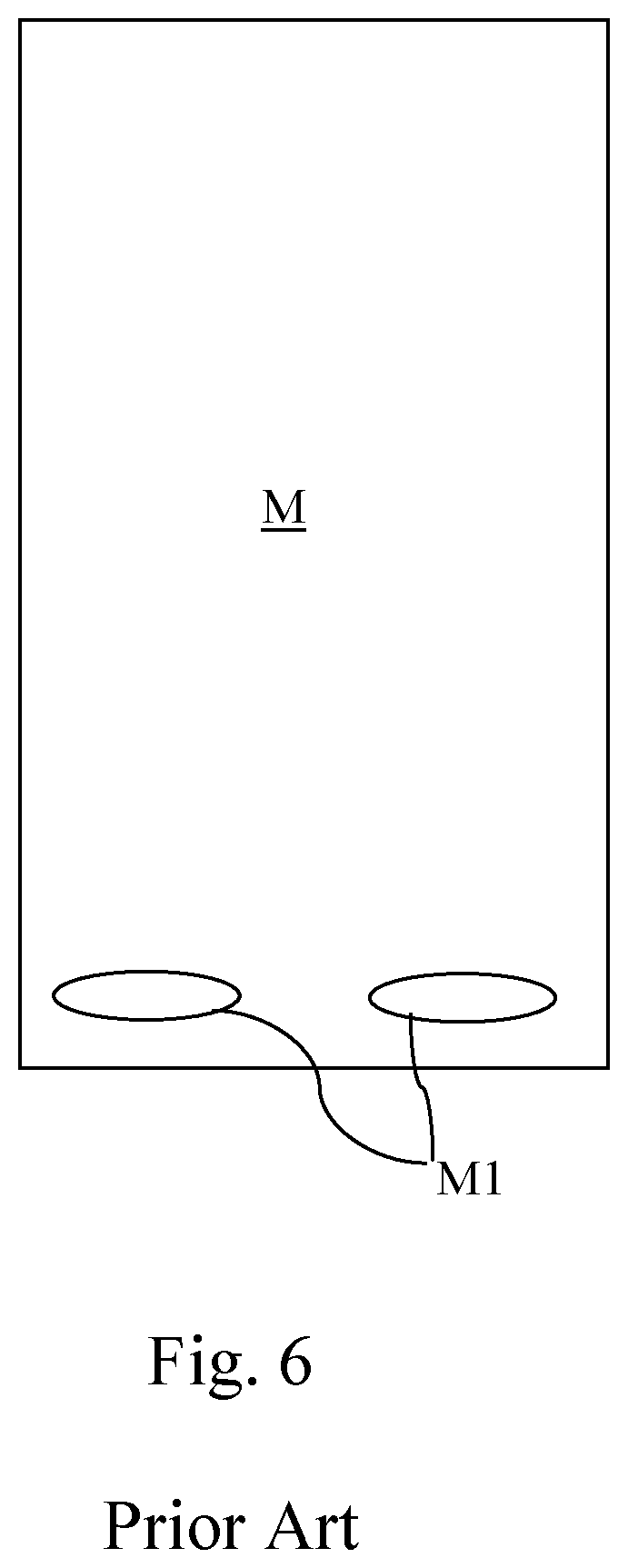
Such battery-modules of the prior art, as shown in FIG. 6, are equipped with at least one, generally a pair of through openings M1, which pass through the parallelepipedal body of the battery-module perpendicular to two reciprocally parallel sides, defining safety or evacuation openings.
In case of damage of the battery-modules, some internal portions of the case open, in a controlled way, towards said through openings M1.
Furthermore such battery-modules tend to heat during their use, thus they are generally cooled by a liquid circuit or a by forced air. Both the battery-modules and the respective cooling circuit are housed in the vehicle, in appropriate spaces made within the vehicle body, or externally between the side members in case of industrial vehicles.
SUMMARY OF THE INVENTION
The aim of the present invention is to provide a housing for vehicle lithium battery-modules and the like, particularly adapted to accommodate a plurality of monolithic battery-modules.
The idea at the basis of the present invention is to make a single device that is able to extract the heat produced and dispersed by one or more battery-modules and to facilitate, if necessary, the discharge of hot gases released by one or more damaged battery-modules, providing the cooling of such gases, for the safety of the persons and goods that can be in close proximity.
The object of the present invention is a housing of vehicle lithium battery-modules, in accordance with claim 1.
Advantageously, portions of the internal surfaces for gathering and conveying the heat cooperate to define evacuation channels of the hot gases developed by the battery-modules in case of exceeding the higher overheating limit.
Furthermore, such channels are gastight, so that on the one hand, eventual hot gases cannot hit other components inserted in the housing itself, by damaging it; on the other hand, the housing is isolated from the external environment and thus it is not subject to dust accumulations, liquids, etc.
The object of the present invention is also a vehicle comprising said housing of vehicle battery-modules, as described more fully in the claims, which are an integral part of this description.
BRIEF DESCRIPTION OF THE FIGURES
Further purposes and advantages of the present invention will become clear from the following detailed description of a preferred embodiment (and of its alternative embodiments) and the drawings that are attached hereto, which are merely illustrative and non-limitative, in which:
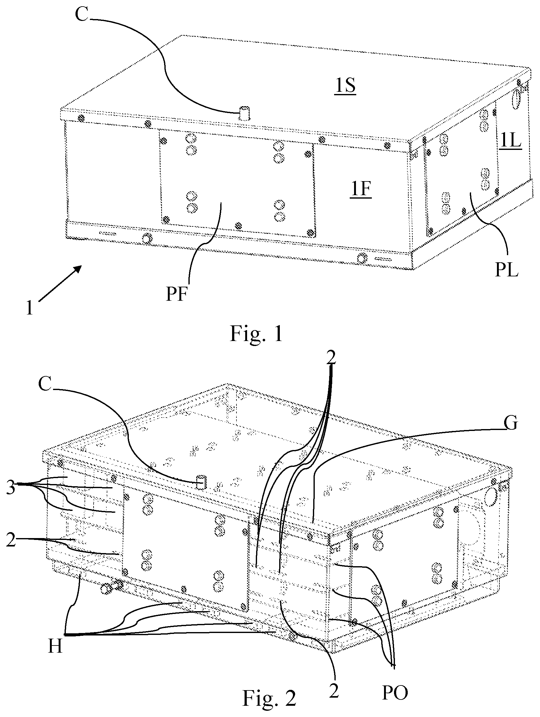
FIG. 1 shows a perspective view of the housing according to the present invention,
FIG. 2 shows the same view as FIG. 1 with some parts shown in transparency;
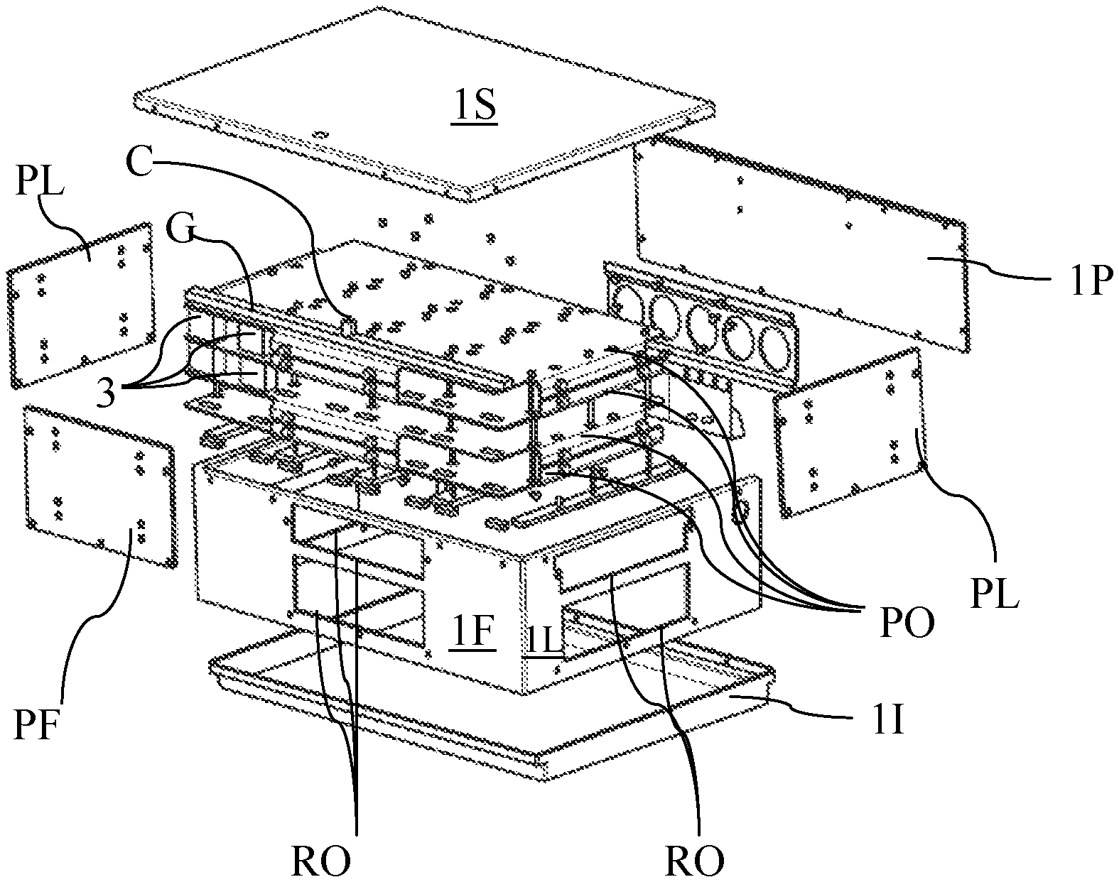
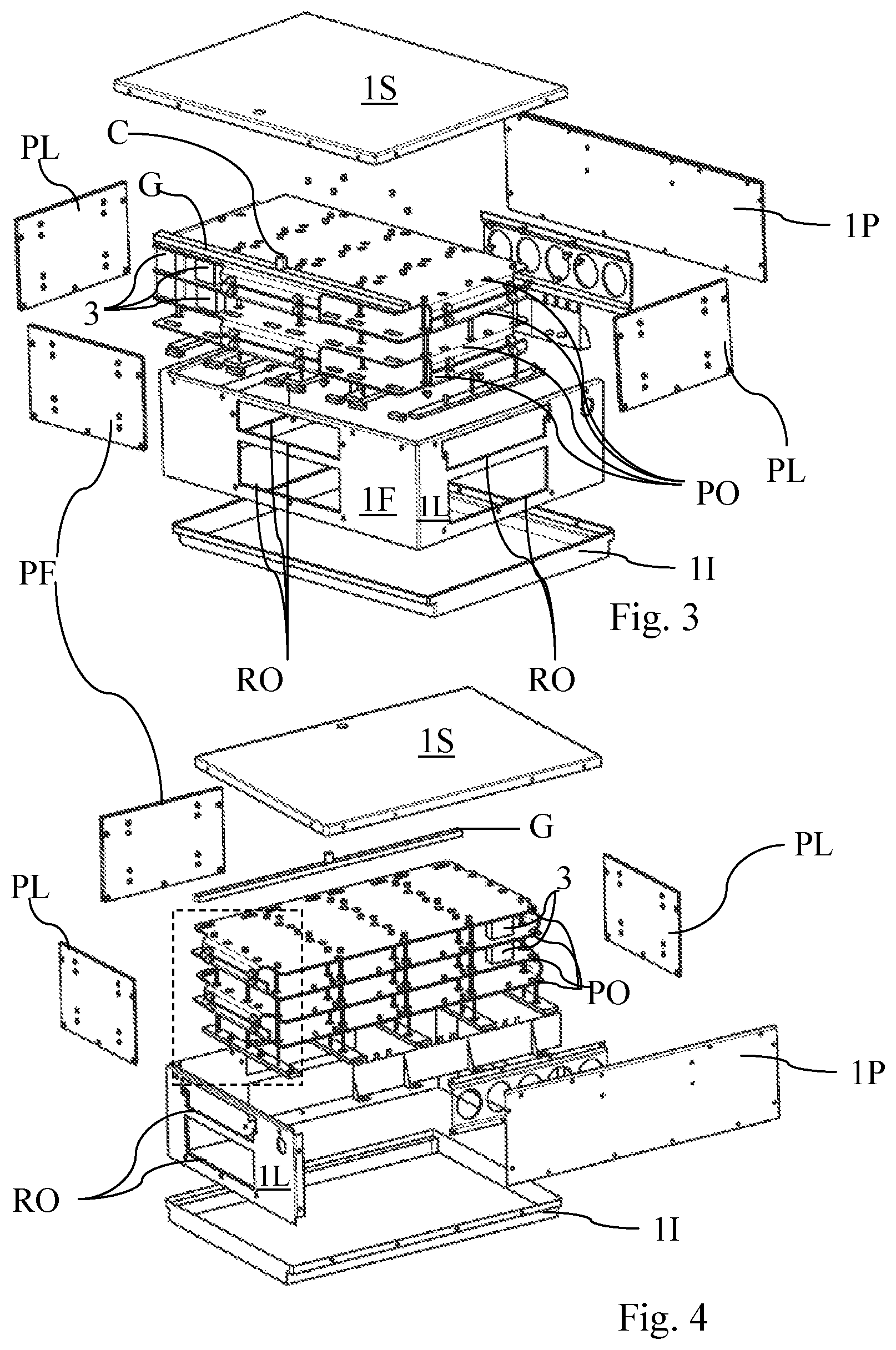
FIGS. 3 and 4 show two exploded views of FIG. 1 according to two different perspective views;
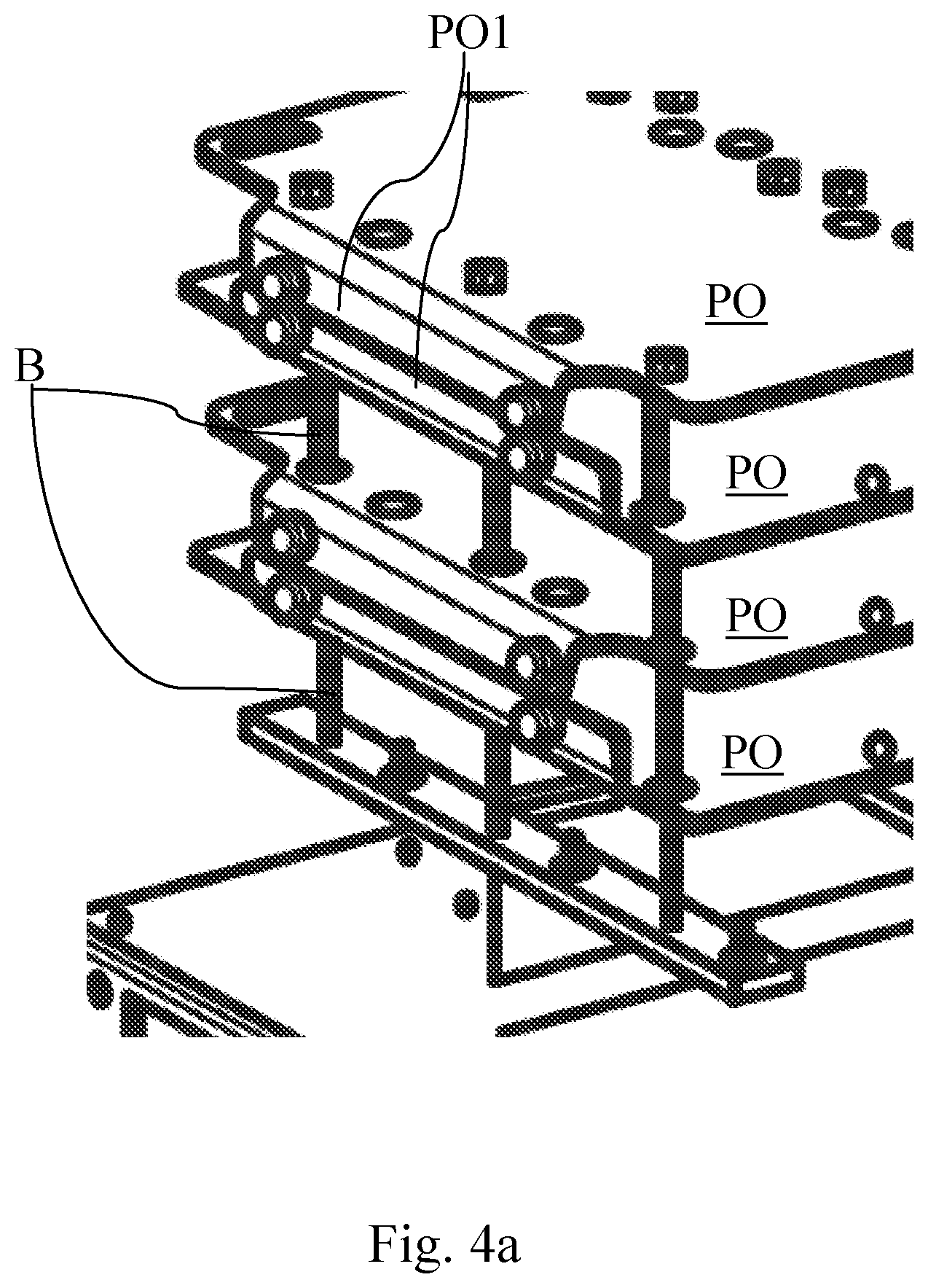
FIG. 4a shows an enlarged detail of FIG. 4,
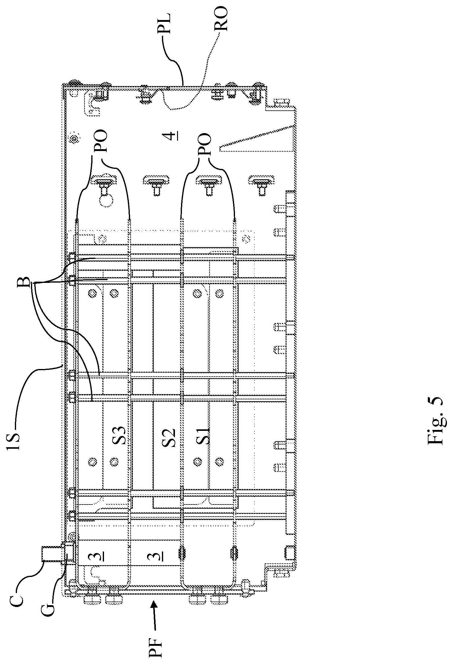
FIG. 5 shows a side view with the parts in transparency of FIG. 1,
FIG. 6 shows a top view of a battery-module per se known, the device that is object of the present invention being intended to be used with a plurality of them.
In the figures the same reference numbers and letters identify the same elements or components.
DETAILED DESCRIPTION OF PREFERRED EMBODIMENTS OF THE INVENTION
With reference to FIGS. 1-5 the housing that is object of the present invention 1 has a parallelepipedal shape with six sides, each side being formed by a surface/plate, of which the front surface/plate 1F, the two lateral surfaces/places 1L, the upper surface/plate 1S, the lower surface/plate 1I, the rear surface/plate 1P.
Preferably, the upper and lower plates are made with folded edges, so that they can be easily assembled with the perimetral plates, namely the front/lateral/rear plates.
The latter can be advantageously obtained by punching or milling a single strip of material, subsequently folded.
With reference to FIGS. 3 and 4, it can be clearly seen that the lateral plates and the front plate are made in a single piece.
If the perimetral plates, namely the front/lateral/rear plates, are made of a highly dispersant material, such as aluminium, copper or stainless steel, then the plates themselves contribute to the dispersion of the battery-module heat towards the outside.
Otherwise, within the lateral and front plates, appropriate openings RO are made, preferably having a rectangular shape. Such openings RO are closed by respective thermal dispersion plates: a front thermal dispersion plate PF and two lateral thermal dispersion plates PL.
In this case, such dispersion plates represent the means through which the heat produced by the battery-modules is dissipated in the external environment.
In case it is necessary to increase the dispersing capacity of the dispersion plates PL, they can be made with finned external surfaces or by using, as dispersion plates PL, external surfaces of a liquid heat exchanger. Both such solution are able to increase the efficiency of the passive heat exchange.
With reference to FIGS. 3 and 4, it is possible to see that, horizontal plates PO are arranged inside the housing 1, namely parallel to the upper plate 1S and the lower plate 1I. Such plates are intended to gather the heat dissipated by the battery-modules M inside the housing 1, to convey it towards the perimetral thermal dispersion plates.
The horizontal plates PO are parallel and are constrained to each other, by means of stud bolts B, which press the horizontal plates to the upper face of the battery-modules M (not shown). Thus, the horizontal plates PO are intended to come into direct contact with the surface of the battery-modules shown in FIG. 6.
The horizontal plates have edges PO1 folded by 90.degree., at least in the proximity of the aforementioned openings RO of the front and lateral plates, so that they can be directly connected to the front and lateral thermal dispersion plates, ensuring a thermal continuity.
The battery-modules M shown in FIG. 6 have a parallelepipedal shape with a pair of evacuation openings M1 to allow the evacuation of hot gases given off in case of a breaking of the battery-module itself.
Each horizontal plate is provided with appropriate slots 2, that can be seen more clearly in FIG. 2, corresponding to the evacuation openings M1 of the battery-modules M.
Each slot is provided with an appropriate gasket on both faces of the same horizontal plate.
The battery-modules are arranged in layers S1, S2, S3, in the housing 1, see FIG. 5. A first lower layer S1, wherein the battery-modules M are one next to the other on a first horizontal plate PO. A second horizontal plate covers the first layer of battery-modules, so that two opposite sides of the same battery-modules are in contact with two horizontal plates parallel to each other, namely to form a sandwich.
Battery-modules M are arranged so that the evacuation openings M1 are reciprocally aligned parallel to one of the sides of the housing 1, preferably to the front plate 1F. In particular, the evacuation openings are arranged vertically, namely with their development axis being vertical.
Over the second horizontal place, further battery-modules M are accommodated to form a second layer S2. Also for this layer, battery-modules are placed one next to the other, so that the evacuation openings M1 are aligned parallel to the aforementioned one of the sides of the housing, corresponding exactly to the evacuation openings of the first layer of battery-modules M. Thus there is a vertical alignment between the different layers of battery-modules.
Thus, (pairs of) vertical evacuation channel are defined, being continuous and gastight towards the inside of the housing, which pass through the different layers of battery-modules M ending up outside the housing.
A horizontal canalization G is arranged over the last horizontal place, in correspondence of such channels, which gathers the different vertical channels. Such canalization contributes to reduce the gas temperature before they leave the housing. A chimney C makes said horizontal canalization G communicate with the outside of the housing 1, through the upper plate 1S. Preferably, such chimney C is arranged in medial position with respect to the distribution of the battery-modules M.
Further openings are made in the lower plate 1I, always in correspondence of the openings M1 in the battery-modules, so as to facilitate the gas circulation from the bottom upwards.
Also the lower plate 1I is equipped with appropriate gaskets H which surround the aforementioned openings so as to contribute to the realization of the gastight vent channels towards the inside of the housing 1.
Advantageously, the channels defined are open only towards the outside of the housing through a check valve, thus, in case of a failure of only one of the battery-modules, hot gases are evacuated without hitting the internal circuitry and internal components or further adjacent battery-modules of the battery-module pack.
Furthermore, a path is forced through the aforementioned canalization G with the aim to cool the hot gases before they go out, for the safety of people that may possible be in close proximity.
It is thus evident that the horizontal plates themselves, from the one hand have a function of conveying the heat given off by the battery-modules. On the other hand, they contribute to define evacuation channels of the hot gases that are given off in case of a damage of a battery.
With reference to FIG. 5, the portion 4 inside the housing is intended to accommodate the electronic circuitry that and interrupters and protections are usually associated to the battery-modules.
Such circuitry, by virtue of the present invention, is protected from being hit by the hot gases in case of a damage of at least one battery.
Such internal area is accessible from outside through the opening RO.
With reference to FIG. 2, in case not all the available allocations for housing the battery-modules are occupied, some evacuation channels would be incomplete, and will communicate with the internal part of the housing. To avoid this, tubular elements 3 are provided, arranged with their development axis perpendicular to the horizontal plates PO, in order to ensure the continuity of the aforementioned channels.
Advantageously, such tubular elements allow the housing to become modular, namely a lower number of battery-modules with respect to its capacity can be installed therein.
It is worth noting that, by virtue of the operativeness of the aforementioned evacuation channels of the hot gases, the vertical or horizontal directions are immediately identified by the person skilled in the art, identifying them also from the orientation of the reference signs with reference to the FIGS. 1-5 themselves.
It will be apparent to the person skilled in the art that other alternative and equivalent embodiments of the invention can be conceived and reduced to practice without departing from the scope of the invention.
From the description set forth above it will be possible for the person skilled in the art to embody the invention with no need of describing further construction details. The elements and the characteristics described in the different preferred embodiments may be combined without departing from the scope of the present application. What is described in the description of the prior art, if not explicitly excluded in the detailed description, has to be considered in combination with the characteristics of the present invention, forming an integral part of the present invention.
* * * * *
D00000
D00001
D00002
D00003
D00004
D00005
XML
uspto.report is an independent third-party trademark research tool that is not affiliated, endorsed, or sponsored by the United States Patent and Trademark Office (USPTO) or any other governmental organization. The information provided by uspto.report is based on publicly available data at the time of writing and is intended for informational purposes only.
While we strive to provide accurate and up-to-date information, we do not guarantee the accuracy, completeness, reliability, or suitability of the information displayed on this site. The use of this site is at your own risk. Any reliance you place on such information is therefore strictly at your own risk.
All official trademark data, including owner information, should be verified by visiting the official USPTO website at www.uspto.gov. This site is not intended to replace professional legal advice and should not be used as a substitute for consulting with a legal professional who is knowledgeable about trademark law.