Dual layer deduplication for a file system running over a deduplicated block storage
Schneider , et al.
U.S. patent number 10,713,221 [Application Number 16/048,763] was granted by the patent office on 2020-07-14 for dual layer deduplication for a file system running over a deduplicated block storage. This patent grant is currently assigned to EMC IP Holding Company LLC. The grantee listed for this patent is EMC IP Holding Company LLC. Invention is credited to Amitai Alkalay, Assaf Natanzon, Zvi Schneider.


| United States Patent | 10,713,221 |
| Schneider , et al. | July 14, 2020 |
Dual layer deduplication for a file system running over a deduplicated block storage
Abstract
An aspect of dual layer deduplication for a file system running over a deduplication block storage system includes accessing a file by a file system driver of the file system. The file is stored as one of a plurality of files in the file system. A further aspect includes breaking the file down into multiple blocks and generating chunks from the blocks. For at least one of the chunks, a trail of zeros is added until a size of a respective one of the chunks is a multiple of a block size of the deduplication block storage system.
| Inventors: | Schneider; Zvi (Tel Aviv, IL), Alkalay; Amitai (Kadima, IL), Natanzon; Assaf (Tel Aviv, IL) | ||||||||||
|---|---|---|---|---|---|---|---|---|---|---|---|
| Applicant: |
|
||||||||||
| Assignee: | EMC IP Holding Company LLC
(Hopkinton, MA) |
||||||||||
| Family ID: | 69178435 | ||||||||||
| Appl. No.: | 16/048,763 | ||||||||||
| Filed: | July 30, 2018 |
Prior Publication Data
| Document Identifier | Publication Date | |
|---|---|---|
| US 20200034452 A1 | Jan 30, 2020 | |
| Current U.S. Class: | 1/1 |
| Current CPC Class: | G06F 16/1752 (20190101); G06F 3/0608 (20130101); G06F 16/1748 (20190101); G06F 16/13 (20190101); G06F 3/0689 (20130101); G06F 3/0641 (20130101) |
| Current International Class: | G06F 17/00 (20190101); G06F 16/13 (20190101); G06F 16/174 (20190101) |
| Field of Search: | ;707/600-899 |
References Cited [Referenced By]
U.S. Patent Documents
| 7203741 | April 2007 | Marco et al. |
| 7719443 | May 2010 | Natanzon |
| 7840536 | November 2010 | Ahal et al. |
| 7840662 | November 2010 | Natanzon |
| 7844856 | November 2010 | Ahal et al. |
| 7860836 | December 2010 | Natanzon et al. |
| 7882286 | February 2011 | Natanzon et al. |
| 7934262 | April 2011 | Natanzon et al. |
| 7958372 | June 2011 | Natanzon |
| 8037162 | October 2011 | Marco et al. |
| 8041940 | October 2011 | Natanzon et al. |
| 8060713 | November 2011 | Natanzon |
| 8060714 | November 2011 | Natanzon |
| 8103937 | January 2012 | Natanzon et al. |
| 8108634 | January 2012 | Natanzon et al. |
| 8214612 | July 2012 | Natanzon |
| 8250149 | August 2012 | Marco et al. |
| 8271441 | September 2012 | Natanzon et al. |
| 8271447 | September 2012 | Natanzon et al. |
| 8332687 | December 2012 | Natanzon et al. |
| 8335761 | December 2012 | Natanzon |
| 8335771 | December 2012 | Natanzon et al. |
| 8341115 | December 2012 | Natanzon et al. |
| 8370648 | February 2013 | Natanzon |
| 8380885 | February 2013 | Natanzon |
| 8392680 | March 2013 | Natanzon et al. |
| 8429362 | April 2013 | Natanzon et al. |
| 8433869 | April 2013 | Natanzon et al. |
| 8438135 | May 2013 | Natanzon et al. |
| 8464101 | June 2013 | Natanzon et al. |
| 8478955 | July 2013 | Natanzon et al. |
| 8495304 | July 2013 | Natanzon et al. |
| 8510279 | August 2013 | Natanzon et al. |
| 8521691 | August 2013 | Natanzon |
| 8521694 | August 2013 | Natanzon |
| 8543609 | September 2013 | Natanzon |
| 8583885 | November 2013 | Natanzon |
| 8600945 | December 2013 | Natanzon et al. |
| 8601085 | December 2013 | Ives et al. |
| 8627012 | January 2014 | Derbeko et al. |
| 8683592 | March 2014 | Dotan et al. |
| 8694700 | April 2014 | Natanzon et al. |
| 8706700 | April 2014 | Natanzon et al. |
| 8712962 | April 2014 | Natanzon et al. |
| 8719497 | May 2014 | Don et al. |
| 8725691 | May 2014 | Natanzon |
| 8725692 | May 2014 | Natanzon et al. |
| 8726066 | May 2014 | Natanzon et al. |
| 8738813 | May 2014 | Natanzon et al. |
| 8745004 | June 2014 | Natanzon et al. |
| 8751828 | June 2014 | Raizen et al. |
| 8769336 | July 2014 | Natanzon et al. |
| 8805786 | August 2014 | Natanzon |
| 8806161 | August 2014 | Natanzon |
| 8825848 | September 2014 | Dotan et al. |
| 8832399 | September 2014 | Natanzon et al. |
| 8850143 | September 2014 | Natanzon |
| 8850144 | September 2014 | Natanzon et al. |
| 8862546 | October 2014 | Natanzon et al. |
| 8892835 | November 2014 | Natanzon et al. |
| 8898112 | November 2014 | Natanzon et al. |
| 8898409 | November 2014 | Natanzon et al. |
| 8898515 | November 2014 | Natanzon |
| 8898519 | November 2014 | Natanzon et al. |
| 8914595 | December 2014 | Natanzon |
| 8924668 | December 2014 | Natanzon |
| 8930500 | January 2015 | Marco et al. |
| 8930947 | January 2015 | Derbeko et al. |
| 8935498 | January 2015 | Natanzon |
| 8949180 | February 2015 | Natanzon et al. |
| 8954673 | February 2015 | Natanzon et al. |
| 8954796 | February 2015 | Cohen et al. |
| 8959054 | February 2015 | Natanzon |
| 8977593 | March 2015 | Natanzon et al. |
| 8977826 | March 2015 | Meiri et al. |
| 8990495 | March 2015 | Hallak et al. |
| 8996460 | March 2015 | Frank et al. |
| 8996461 | March 2015 | Natanzon et al. |
| 8996827 | March 2015 | Natanzon |
| 9003138 | April 2015 | Natanzon et al. |
| 9026696 | May 2015 | Natanzon et al. |
| 9031913 | May 2015 | Natanzon |
| 9032160 | May 2015 | Natanzon et al. |
| 9037818 | May 2015 | Natanzon et al. |
| 9063994 | June 2015 | Natanzon et al. |
| 9069479 | June 2015 | Natanzon |
| 9069709 | June 2015 | Natanzon et al. |
| 9081754 | July 2015 | Natanzon et al. |
| 9081842 | July 2015 | Natanzon et al. |
| 9087008 | July 2015 | Natanzon |
| 9087112 | July 2015 | Natanzon et al. |
| 9104326 | August 2015 | Frank et al. |
| 9104529 | August 2015 | Derbeko et al. |
| 9110914 | August 2015 | Frank et al. |
| 9116811 | August 2015 | Derbeko et al. |
| 9128628 | September 2015 | Natanzon et al. |
| 9128855 | September 2015 | Natanzon et al. |
| 9134914 | September 2015 | Derbeko et al. |
| 9135119 | September 2015 | Natanzon et al. |
| 9135120 | September 2015 | Natanzon |
| 9146878 | September 2015 | Cohen et al. |
| 9152339 | October 2015 | Cohen et al. |
| 9152578 | October 2015 | Saad et al. |
| 9152814 | October 2015 | Natanzon |
| 9158578 | October 2015 | Derbeko et al. |
| 9158630 | October 2015 | Natanzon |
| 9160526 | October 2015 | Raizen et al. |
| 9177670 | November 2015 | Derbeko et al. |
| 9189339 | November 2015 | Cohen et al. |
| 9189341 | November 2015 | Natanzon et al. |
| 9201736 | December 2015 | Moore et al. |
| 9208162 | December 2015 | Hallak et al. |
| 9223659 | December 2015 | Natanzon et al. |
| 9225529 | December 2015 | Natanzon et al. |
| 9235481 | January 2016 | Natanzon et al. |
| 9235524 | January 2016 | Derbeko et al. |
| 9235632 | January 2016 | Natanzon |
| 9244997 | January 2016 | Natanzon et al. |
| 9256605 | February 2016 | Natanzon |
| 9274718 | March 2016 | Natanzon et al. |
| 9275063 | March 2016 | Natanzon |
| 9286052 | March 2016 | Solan et al. |
| 9305009 | April 2016 | Bono et al. |
| 9323750 | April 2016 | Natanzon et al. |
| 9330155 | May 2016 | Bono et al. |
| 9336094 | May 2016 | Wolfson et al. |
| 9336230 | May 2016 | Natanzon |
| 9367260 | June 2016 | Natanzon |
| 9378096 | June 2016 | Erel et al. |
| 9378106 | June 2016 | Ben-Moshe et al. |
| 9378219 | June 2016 | Bono et al. |
| 9378261 | June 2016 | Bono et al. |
| 9383937 | July 2016 | Frank et al. |
| 9389800 | July 2016 | Natanzon et al. |
| 9396243 | July 2016 | Halevi et al. |
| 9405481 | August 2016 | Cohen et al. |
| 9405684 | August 2016 | Derbeko et al. |
| 9405765 | August 2016 | Natanzon |
| 9411535 | August 2016 | Shemer et al. |
| 9459804 | October 2016 | Natanzon et al. |
| 9460028 | October 2016 | Raizen et al. |
| 9471579 | October 2016 | Natanzon |
| 9477407 | October 2016 | Marshak et al. |
| 9501542 | November 2016 | Natanzon |
| 9507732 | November 2016 | Natanzon et al. |
| 9507845 | November 2016 | Natanzon et al. |
| 9514138 | December 2016 | Natanzon et al. |
| 9524218 | December 2016 | Veprinsky et al. |
| 9529885 | December 2016 | Natanzon et al. |
| 9535800 | January 2017 | Natanzon et al. |
| 9535801 | January 2017 | Natanzon et al. |
| 9547459 | January 2017 | BenHanokh et al. |
| 9547591 | January 2017 | Natanzon et al. |
| 9552405 | January 2017 | Moore et al. |
| 9557921 | January 2017 | Cohen et al. |
| 9557925 | January 2017 | Natanzon |
| 9563517 | February 2017 | Natanzon et al. |
| 9563684 | February 2017 | Natanzon et al. |
| 9575851 | February 2017 | Natanzon et al. |
| 9575857 | February 2017 | Natanzon |
| 9575894 | February 2017 | Natanzon et al. |
| 9582382 | February 2017 | Natanzon et al. |
| 9588703 | March 2017 | Natanzon et al. |
| 9588847 | March 2017 | Natanzon et al. |
| 9594822 | March 2017 | Natanzon et al. |
| 9600377 | March 2017 | Cohen et al. |
| 9606870 | March 2017 | Meiri et al. |
| 9619543 | April 2017 | Natanzon et al. |
| 9632881 | April 2017 | Natanzon |
| 9665305 | May 2017 | Natanzon et al. |
| 9710177 | July 2017 | Natanzon |
| 9720618 | August 2017 | Panidis et al. |
| 9722788 | August 2017 | Natanzon et al. |
| 9727429 | August 2017 | Moore et al. |
| 9733969 | August 2017 | Derbeko et al. |
| 9737111 | August 2017 | Lustik |
| 9740572 | August 2017 | Natanzon et al. |
| 9740573 | August 2017 | Natanzon |
| 9740880 | August 2017 | Natanzon et al. |
| 9749300 | August 2017 | Cale et al. |
| 9772789 | September 2017 | Natanzon et al. |
| 9798472 | October 2017 | Natanzon et al. |
| 9798490 | October 2017 | Natanzon |
| 9804934 | October 2017 | Natanzon et al. |
| 9811431 | November 2017 | Natanzon et al. |
| 9823865 | November 2017 | Natanzon et al. |
| 9823973 | November 2017 | Natanzon |
| 9832261 | November 2017 | Don et al. |
| 9846698 | December 2017 | Panidis et al. |
| 9875042 | January 2018 | Natanzon et al. |
| 9875162 | January 2018 | Panidis et al. |
| 9880777 | January 2018 | Bono et al. |
| 9881014 | January 2018 | Bono et al. |
| 9910620 | March 2018 | Veprinsky et al. |
| 9910621 | March 2018 | Golan et al. |
| 9910735 | March 2018 | Natanzon |
| 9910739 | March 2018 | Natanzon et al. |
| 9917854 | March 2018 | Natanzon et al. |
| 9921955 | March 2018 | Derbeko et al. |
| 9933957 | April 2018 | Cohen et al. |
| 9934302 | April 2018 | Cohen et al. |
| 9940205 | April 2018 | Natanzon |
| 9940460 | April 2018 | Derbeko et al. |
| 9946649 | April 2018 | Natanzon et al. |
| 9959061 | May 2018 | Natanzon et al. |
| 9965306 | May 2018 | Natanzon et al. |
| 9990256 | June 2018 | Natanzon |
| 9996539 | June 2018 | Natanzon |
| 10007626 | June 2018 | Saad et al. |
| 10019194 | July 2018 | Baruch et al. |
| 10025931 | July 2018 | Natanzon et al. |
| 10031675 | July 2018 | Veprinsky et al. |
| 10031690 | July 2018 | Panidis et al. |
| 10031692 | July 2018 | Elron et al. |
| 10031703 | July 2018 | Natanzon et al. |
| 10037251 | July 2018 | Bono et al. |
| 10042579 | August 2018 | Natanzon |
| 10042751 | August 2018 | Veprinsky et al. |
| 10055146 | August 2018 | Natanzon et al. |
| 10055148 | August 2018 | Natanzon et al. |
| 10061666 | August 2018 | Natanzon et al. |
| 10067694 | September 2018 | Natanzon et al. |
| 10067837 | September 2018 | Natanzon et al. |
| 10078459 | September 2018 | Natanzon et al. |
| 10082980 | September 2018 | Cohen et al. |
| 10083093 | September 2018 | Natanzon et al. |
| 10095489 | October 2018 | Lieberman et al. |
| 10101943 | October 2018 | Ayzenberg et al. |
| 10108356 | October 2018 | Natanzon et al. |
| 10108507 | October 2018 | Natanzon |
| 10108645 | October 2018 | Bigman et al. |
| 10114581 | October 2018 | Natanzon et al. |
| 10120787 | November 2018 | Shemer et al. |
| 10120925 | November 2018 | Natanzon et al. |
| 10126946 | November 2018 | Natanzon et al. |
| 10133874 | November 2018 | Natanzon et al. |
| 10140039 | November 2018 | Baruch et al. |
| 10146436 | December 2018 | Natanzon et al. |
| 10146639 | December 2018 | Natanzon et al. |
| 10146675 | December 2018 | Shemer et al. |
| 10146961 | December 2018 | Baruch et al. |
| 10148751 | December 2018 | Natanzon |
| 10152246 | December 2018 | Lieberman et al. |
| 10152267 | December 2018 | Ayzenberg et al. |
| 10152384 | December 2018 | Amit et al. |
| 10157014 | December 2018 | Panidis et al. |
| 10185583 | January 2019 | Natanzon et al. |
| 10191677 | January 2019 | Natanzon et al. |
| 10191687 | January 2019 | Baruch et al. |
| 10191755 | January 2019 | Natanzon et al. |
| 10203904 | February 2019 | Natanzon et al. |
| 10210073 | February 2019 | Baruch et al. |
| 10223007 | March 2019 | Natanzon et al. |
| 10223023 | March 2019 | Natanzon et al. |
| 10223131 | March 2019 | Lieberman et al. |
| 10229006 | March 2019 | Natanzon et al. |
| 10229056 | March 2019 | Panidis et al. |
| 10545833 | January 2020 | Bardale |
Other References
|
US. Appl. No. 14/496,783, filed Sep. 25, 2014, Natanzon et al. cited by applicant . U.S. Appl. No. 14/496,790, filed Sep. 25, 2014, Cohen et al. cited by applicant . U.S. Appl. No. 14/559,036, filed Dec. 3, 2014, Natanzon et al. cited by applicant . U.S. Appl. No. 14/753,389, filed Jun. 29, 2015, Nir et al. cited by applicant . U.S. Appl. No. 14/976,719, filed Dec. 21, 2015, Natanzon. cited by applicant . U.S. Appl. No. 14/978,378, filed Dec. 22, 2015, Bigman et al. cited by applicant . U.S. Appl. No. 15/085,145, filed Mar. 30, 2016, Baruch et al. cited by applicant . U.S. Appl. No. 15/274,362, filed Sep. 23, 2016, Baruch et al. cited by applicant . U.S. Appl. No. 15/275,768, filed Sep. 26, 2016, Natanzon et al. cited by applicant . U.S. Appl. No. 15/275,756, filed Sep. 26, 2016, Natanzon et al. cited by applicant . U.S. Appl. No. 15/379,940, filed Dec. 15, 2016, Baruch et al. cited by applicant . U.S. Appl. No. 15/386,754, filed Dec. 21, 2016, Shemer et al. cited by applicant . U.S. Appl. No. 15/380,013, filed Dec. 15, 2016, Baruch et al. cited by applicant . U.S. Appl. No. 15/390,996, filed Dec. 27, 2016, Natanzon et al. cited by applicant . U.S. Appl. No. 15/391,030, filed Dec. 27, 2016, Shemer et al. cited by applicant . U.S. Appl. No. 15/970,243, filed May 3, 2018, Schneider et al. cited by applicant . U.S. Appl. No. 16/052,037, filed Aug. 1, 2018, Schneider et al. cited by applicant . U.S. Appl. No. 16/050,400, filed Jul. 31, 2018, Alkalay et al. cited by applicant . U.S. Appl. No. 16/179,295, filed Nov. 2, 2018, Natanzon et al. cited by applicant . U.S. Appl. No. 16/261,174, filed Jan. 29, 2019, Natanzon et al. cited by applicant. |
Primary Examiner: Woo; Isaac M
Attorney, Agent or Firm: Daly, Crowley Mofford & Durkee, LLP
Claims
What is claimed is:
1. A method for dual layer deduplication for a file system running over a deduplication block storage system, comprising: accessing a file by a file system driver of the file system, the file stored as one of a plurality of files in the file system; breaking the file down into multiple blocks; generating chunks from the blocks, wherein for at least one of the chunks adding a trail of zeros until a size of a respective one of the chunks is a multiple of a block size of the deduplication block storage system, and performing, by the deduplication block storage system, deduplication on the chunks and compression on deduplicated chunks having the trailing zeros; wherein the file includes data and metadata that describes a structure of the data, the metadata for each file including a list of locations where the file is chunked.
2. The method of claim 1, wherein the generating chunks is performed by a variable length chunking algorithm.
3. The method of claim 1, wherein the chunks are one of byte aligned and bit aligned.
4. The method of claim 1, wherein a chunk size for the files is greater than a chunk size for the block deduplication.
5. The method of claim 1, wherein each of the blocks has an equal number of characters.
6. A system for dual layer deduplication for a file system running over a deduplication block storage system, comprising: a memory comprising computer-executable instructions; and a processor executing the computer-executable instructions, the computer-executable instructions when executed by the processor cause the processor to perform operations comprising: accessing a file by a file system driver of the file system, the file stored as one of a plurality of files in the file system; breaking the file down into multiple blocks; generating chunks from the blocks, wherein for at least one of the chunks adding a trail of zeros until a size of a respective one of the chunks is a multiple of a block size of the deduplication block storage system; and performing, by the deduplication block storage system, deduplication on the chunks and compression on deduplicated chunks having the trailing zeros; wherein the file includes data and metadata that describes a structure of the data, the metadata for each file including a list of locations where the file is chunked.
7. The system of claim 6, wherein the generating chunks is performed by a variable length chunking algorithm.
8. The system of claim 6, wherein the chunks are one of byte aligned and bit aligned.
9. The system of claim 6, wherein a chunk size for the files is greater than a chunk size for the block deduplication.
10. The system of claim 6, wherein each of the blocks has an equal number of characters.
11. A computer program product embodied on a non-transitory computer readable medium, the computer program product including instructions that, when executed by a computer causes the computer to perform operations comprising: accessing a file by a file system driver of the file system, the file stored as one of a plurality of files in the file system; breaking the file down into multiple blocks; generating chunks from the blocks, wherein for at least one of the chunks adding a trail of zeros until a size of a respective one of the chunks is a multiple of a block size of the deduplication block storage system; and performing, by the deduplication block storage system, deduplication on the chunks and compression on deduplicated chunks having the trailing zeros; wherein the file includes data and metadata that describes a structure of the data, the metadata for each file including a list of locations where the file is chunked.
12. The computer program product of claim 11, wherein the generating chunks is performed by a variable length chunking algorithm.
13. The computer program product of claim 11, wherein the chunks are one of byte aligned and bit aligned.
14. The computer program product of claim 11, wherein a chunk size for the files is greater than a chunk size for the block deduplication, and wherein each of the blocks has an equal number of characters.
Description
BACKGROUND
Data deduplication (also referred to simply as "deduplication") is a space-saving technology intended to eliminate redundant (duplicate) data (such as, files) on a data storage system. By saving only one instance of a file, disk space can be significantly reduced. For example, if a file of size 10 megabytes (MB) is stored in ten folders of each employee in an organization that has ten employees. Thus, 100 megabytes (MB) of the disk space is consumed to maintain the same file of size 10 megabytes (MB). Deduplication ensures that only one complete copy is saved to a disk. Subsequent copies of the file are only saved as references that point to the saved copy, such that end-users still see their own files in their respective folders. Similarly, a storage system may retain 200 e-mails, each with an attachment of size 1 megabyte (MB). With deduplication, the disk space needed to store each attachment of size 1 megabyte (MB) is reduced to just 1 megabyte (MB) from 200 megabyte (MB) because deduplication only stores one copy of the attachment.
Data deduplication can operate at a file or a block level. File deduplication eliminates duplicate files (as in the example above), but block deduplication processes blocks within a file and saves unique copy of each block. For example, if only a few bytes of a document or presentation or a file are changed, only the changed blocks are saved. The changes made to few bytes of the document or the presentation or the file does not constitute an entirely new file.
SUMMARY
This Summary is provided to introduce a selection of concepts in a simplified form that are further described herein in the Detailed Description. This Summary is not intended to identify key features or essential features of the claimed subject matter, nor is it intended to be used to limit the scope of the claimed subject matter.
One aspect may provide a method for dual layer deduplication for a file system running over a deduplication block storage system. The method includes accessing a file by a file system driver of the file system. The file is stored as one of a plurality of files in the file system. The method further includes breaking the file down into multiple blocks and generating chunks from the blocks. For at least one of the chunks, a trail of zeros is added until a size of a respective one of the chunks is a multiple of a block size of the deduplication block storage system
Another aspect may provide a system for dual layer deduplication for a file system running over a deduplication block storage system. The system includes a memory having computer-executable instructions and a processor. The processor executes the computer-executable instructions. When executed by the processor, the computer-executable instructions cause the processor to perform operations. The operations include accessing a file by a file system driver of the file system. The file is stored as one of a plurality of files in the file system. The operations further include breaking the file down into multiple blocks and generating chunks from the blocks. For at least one of the chunks, a trail of zeros is added until a size of a respective one of the chunks is a multiple of a block size of the deduplication block storage system.
Another aspect may provide a computer program product embodied on a non-transitory computer readable medium. The computer program product includes instructions that, when executed by a computer, causes the computer to perform operations. The operations include accessing a file by a file system driver of the file system. The file is stored as one of a plurality of files in the file system. A further aspect includes breaking the file down into multiple blocks and generating chunks from the blocks. For at least one of the chunks, a trail of zeros is added until a size of a respective one of the chunks is a multiple of a block size of the deduplication block storage system.
BRIEF DESCRIPTION OF THE DRAWING FIGURES
Objects, aspects, features, and advantages of embodiments disclosed herein will become more fully apparent from the following detailed description, the appended claims, and the accompanying drawings in which like reference numerals identify similar or identical elements. Reference numerals that are introduced in the specification in association with a drawing figure may be repeated in one or more subsequent figures without additional description in the specification in order to provide context for other features. For clarity, not every element may be labeled in every figure. The drawings are not necessarily to scale, emphasis instead being placed upon illustrating embodiments, principles, and concepts. The drawings are not meant to limit the scope of the claims included herewith.
FIG. 1A is a block diagram of a content-based storage system having multi-level cache for deduplicated storage;
FIG. 1B illustrates further detail of the system of FIG. 1A;
FIG. 2 is a flow diagram of read and write operations for the system of FIG. 1A;
FIG. 3 is a block diagram of a content-based storage system having a control module with a first cache and a data module with a second cache;
FIG. 4 is a schematic representation of address-to-hash (A2H) mapping in a control module and hash-to-physical (H2P) mapping in a data module for a content-based storage system;
FIG. 5 is a block diagram of a simplified system for implementing dual layer deduplication for a file system running over a deduplication block storage system;
FIG. 6 is a block diagram of sample file system blocks;
FIG. 7 is a flow diagram of a process for implementing dual layer deduplication for a file system running over a deduplication block storage system; and
FIG. 8 is a block diagram of an illustrative computer that can perform at least a portion of the processing described herein.
DETAILED DESCRIPTION
Before describing embodiments of the concepts, structures, and techniques sought to be protected herein, some terms are explained. The following description includes a number of terms for which the definitions are generally known in the art. However, the following glossary definitions are provided to clarify the subsequent description and may be helpful in understanding the specification and claims.
As used herein, the term "storage system" is intended to be broadly construed so as to encompass, for example, private or public cloud computing systems for storing data as well as systems for storing data comprising virtual infrastructure and those not comprising virtual infrastructure. As used herein, the terms "client," "host," and "user" refer, interchangeably, to any person, system, or other entity that uses a storage system to read/write data. In some embodiments, the term "storage device" may also refer to a storage array including multiple storage devices. In certain embodiments, a storage medium may refer to one or more storage mediums such as a hard drive, a combination of hard drives, flash storage, combinations of flash storage, combinations of hard drives, flash, and other storage devices, and other types and combinations of computer readable storage mediums including those yet to be conceived. A storage medium may also refer both physical and logical storage mediums and may include multiple level of virtual to physical mappings and may be or include an image or disk image. A storage medium may be computer-readable, and may also be referred to herein as a computer-readable program medium.
In certain embodiments, the term "I/O request" or simply "I/O" may be used to refer to an input or output request, such as a data read or data write request.
In certain embodiments, a storage device may refer to any non-volatile memory (NVM) device, including hard disk drives (HDDs), solid state drivers (SSDs), flash devices (e.g., NAND flash devices), and similar devices that may be accessed locally and/or remotely (e.g., via a storage attached network (SAN) (also referred to herein as storage array network (SAN)).
In certain embodiments, a storage array (sometimes referred to as a disk array) may refer to a data storage system that is used for block-based, file-based or object storage, where storage arrays can include, for example, dedicated storage hardware that contains spinning hard disk drives (HDDs), solid-state disk drives, and/or all-flash drives (e.g., the XtremIO all flash drive, available from DELL/EMC of Hopkinton Mass.). In certain embodiments, a data storage entity may be any one or more of a file system, object storage, a virtualized device, a logical unit, a logical unit number, a logical volume, a logical device, a physical device, and/or a storage medium.
In certain embodiments, a physical storage unit may be a physical entity, such as a disk or an array of disks, for storing data in storage locations that can be accessed by address, where physical storage unit is used interchangeably with physical volume. In certain embodiments, a data storage entity may be any one or more of a file system, object storage, a virtualized device, a logical unit, a logical unit number, a logical volume, a logical device, a physical device, and/or a storage medium.
In certain embodiments, an image may be a copy of a logical storage unit at a specific point in time. In certain embodiments, a clone may be a copy or clone of the image or images, and/or drive or drives of a first location at a second location. In some embodiments, a clone may be made up of a set of objects.
In certain embodiments, a snapshot may refer to differential representations of an image, i.e. the snapshot may have pointers to the original volume, and may point to log volumes for changed locations. In certain embodiments, a snapshot may refer to differential representations of the state of a system. Snapshots may be combined into a snapshot array, which may represent different images over a time period or different states of a system over a time period.
In certain embodiments, a journal may be a record of write transactions (e.g., I/O data) issued to a storage system, which may be used to maintain a duplicate storage system, and to roll back the duplicate storage system to a previous point in time. In some embodiments, each entry in a journal contains, apart from the I/O data itself, I/O metadata that can include information such as a volume identifier (ID), the I/O block offset within the volume, the I/O length, and a time stamp of the I/O.
In certain embodiments, XtremIO, available from Dell EMC of Hopkinton, Mass.) is a type of content addressable storage array that uses all flash technology. Flash, as is understood, is a solid-state (SS) random access media type that can read any address range with no latency penalty, in comparison to a hard disk drive (HDD) which has physical moving components which require relocation when reading from different address ranges and thus significantly increasing the latency for random I/O data.
In certain embodiments, an X-page is a predetermined-size aligned chunk as the base unit for memory and disk operations. In certain embodiments described in the present description, the X-Page size is referred to as having 4 KB; however other smaller or larger values can be used as well, and nothing in the design is limited to a specific value.
In certain embodiments, a logical X-page address is the logical address of an X-page, containing a LUN identifier as well as the offset of the X-page within the LUN.
In certain embodiments, a data protection strategy that can be advantageous for use with computer systems, especially networked storage systems, is checkpointing. A checkpoint, as used herein, contains a consistent point in time image of an entire system, including configuration, logical volume mapping metadata, physical on disk layout metadata, and actual user data. In certain embodiments, a checkpoint preserves the state of a system at a given point in time by saving one or more snapshots of, for example, a file system, or an application at one or more points in time. A checkpoint can preserve a snapshot of an application's state, so that it can restart from that point in case of failure, which can be useful for long running applications that are executed in failure-prone computing systems. If a checkpoint is used, an application periodically writes large volumes of snapshot data to persistent storage in an attempt to capture its current state. Thus, if there is a failure, the application can recover by rolling-back its execution state to a previously saved checkpoint.
In certain embodiments, a "checkpoint" refers at least to an entity created by a checkpoint process, where the checkpoint process performs actions to preserve the state of an apparatus, system, or other entity (including software entities) at a particular time. Advantageously, a checkpoint includes information such as user data, the configuration of the apparatus, user metadata, and other information related to the internal state of the apparatus or system. For example, some storage systems (including XtremIO), in accordance with certain embodiments herein, also provide some kind of checkpoint feature, to provide an ability to preserve system state including user data and metadata at some defined point in time in order to restore this state after system malfunction or corruption. In certain embodiments, the checkpoint corresponds to a frozen, immutable re representation of the state of a system or apparatus at certain point in time, including user data, metadata, and the system configuration. In certain embodiments, the checkpoint is stored in a dedicated, reserved location within the system. In certain embodiments, the checkpoint is able to be created in an online, dynamic environment, where the checkpoint creation is transparent to entities having I/O interactions with the system.
For a file system, the accuracy and consistency of a file system is necessary to relate applications and data, so a checkpoint provides a way to provide periodic backup of file server state to allow system recovery in the event of faults or failures. When data corruption is detected, one of the checkpoints can be used for file system recovery. Similarly, a checkpoint, in a virtualization context, is a snapshot of the state of a virtual machine. Like a restore point in MICROSOFT WINDOWS operating systems, a checkpoint allows an administrator to restore an entity (e.g., a computer system, a file system, an application, a virtual machine, etc.) to a previous state. Checkpoints also can be used to create backups before conducting updates. Should an update fail or cause problems, an administrator can return the virtual machine to its state prior to the update. A recover action is used to return the system to the checkpoint state.
It is envisioned that at least some embodiments herein are usable with one or more of the embodiments described in certain commonly owned U.S. patents, including: U.S. Pat. No. 8,990,495 ("Method and System for Storing Data in RAID Memory Devices"); U.S. Pat. No. 9,104,326 ("Scalable Block Data Storage Using Content Addressing") (hereinafter "'326 patent"); and U.S. Pat. No. 9,606,870 ("Data Reduction Techniques in a Flash-Based Key/Value Cluster Storage"), each of which is hereby incorporated by reference.
While vendor-specific terminology may be used herein to facilitate understanding, it is understood that the concepts, techniques, and structures sought to be protected herein are not limited to use with any specific commercial products. In addition, to ensure clarity in the disclosure, well-understood methods, procedures, circuits, components, and products are not described in detail herein.
The phrases, "such as," "for example," "e.g.," "exemplary," and variants thereof, are used herein to describe non-limiting embodiments and are used herein to mean "serving as an example, instance, or illustration." Any embodiments herein described via these phrases and/or variants is not necessarily to be construed as preferred or advantageous over other embodiments and/or to exclude the incorporation of features from other embodiments. In addition, the word "optionally" is used herein to mean that a feature or process, etc., is provided in some embodiments and not provided in other embodiments." Any particular embodiment of the invention may include a plurality of "optional" features unless such features conflict.
FIG. 1A shows an illustrative content-based data storage system 100 with deduplication that may have multi-level data caches in accordance with embodiments of the disclosure. In the illustrated embodiment, first, second, third, and fourth nodes 102, 104, 106, 108 can be interconnected by a switch 110 via a switch interface 111. The first node 102 can include a control system 114 and a data system 116. In embodiments, separate data and control planes may be provided by the control and data systems 114, 116. The control system 114 may control execution of read and write commands to the storage devices 112. The data systems 116 may be connected to the storage devices 112 and, under control of a respective control system 114, may pass data to and/or from the storage devices via suitable storage drivers 113.
The data and/or control systems 114, 116 may retain extracts of the data stored in the storage devices 112. In embodiments, the data extracts may be generated by cryptographic hashing of the data content in the data blocks. In embodiments, the extracts may be used for content addressing of the data blocks to the physical storage devices 112.
The second node 104 can include a hash system 117 to generate the hash/extract, which can be referred to as a content fingerprint for the data blocks. The second node 104 can also include a routing system 118, along with a switch interface 111 and a SAN interface 115. The routing system 118 may terminate storage and retrieval operations and distribute commands to control systems 114 that may be selected for the operation in such a way as to retain balanced usage within the system. In the illustrated embodiment, the third node 106 can be similar to the first node 102 and the fourth node 108 can be similar to the second node 108.
The routing systems 118 may use the hash values calculated from data blocks to select control systems 114 for distribution. More particularly, selection of the control system 114 may use hash values, or may rely on the user address and not on the content (hash). The hash value may, however, be used for selecting the data system 116, and for setting the physical location for data storage within the data system.
In example embodiments, control modules 114 can include a C cache 115 and the data modules 116 can include a D cache 117. As explained more fully below, the C cache 115 can include addresses, address hashes, and physical data location information and the D cache 117 can include, for each bucket, a filter, a hash to address, and bucket information.
In some examples, the system 100 may employ more than a single type of memory technology, including a mix of more than one Flash technology (e.g., single level cell (SLC) flash and multilevel cell (MLC) flash), and a mix of Flash and DRAM technologies. In certain embodiments, data mapping may optimize performance and life span by taking advantage of the different access speeds and different write/erase cycle limitations of the various memory technologies.
FIG. 1B is an example of a system that can include a hash system 150 communicatively coupled to a routing system 152, which can be communicatively coupled to a control system 154 and a data system 156. The data system 156 can be communicatively coupled to any practical number of memory devices 158. The routing system 152 can route read/write commands from a host (not shown) to control and data systems 154, 156 for execution. In embodiments, the data content-based mapping to physical storage 158 can distribute workload relatively evenly and provide separation of the control and data paths. Read and write operations to the SSDs 158 can be used to generate priority values for the data blocks, as described more fully below.
FIG. 2 shows an example IO operation. A host 217 may issue a read command for a logical block address, which is shown as address "6," via a Fibre Channel or iSCSI port, for example. The routing system 218 may receive the read command and determine a requested address range in data blocks of 4K, for example, and pass the address information to the control system 214. The control system 214 may look up address 6 to obtain the hash value, which is shown as H6. This may be referred to as address-to-hash (A2H) lookup. The H6 hash value may be passed to the data system 216 which can perform a look up of the H6 hash value in a hash-to-physical address (H2P) table to read the physical address for the data. In the example, the physical address is shown as "G." The data system 216 can use the physical address to read the data block (DB) at physical address Gin the SSD 221. A reference count can correspond to a number of times the hash value is referenced in physical storage. In embodiments, write reference information can be modified for each unique and/or deduplicated write and access reference information can be modified for each read and/or write access.
For a write operation from a host, the routing system 218 can receive the write data and can segment the data stream into data blocks and generate hash values for the data blocks. The hash value can be provided to the control system 214 to determine if the write data is unique. If unique, the hash value can be placed in an address mapping. The control system 214 can pass the hash value to the data system 216, which can assign the hash value to a physical address and write the data block(s) to the SSD at the physical address. In embodiments, the write reference information and/or the access reference information, can be modified, e.g., incremented,
If the hash value generated by the routing system 218 is not unique, the control system 214 can determine that data already exists at the physical address for the hash value. Since the data already exists, the data system 216 can increment the write reference information for the data block. In embodiments, the access reference information can also be modified. The data may not be written to the SSD. Deduplication may refer to a write operation where a hash for a data block is found not be unique and the non-unique data block is not written to physical storage. The reference count for the non-unique hash may be incremented.
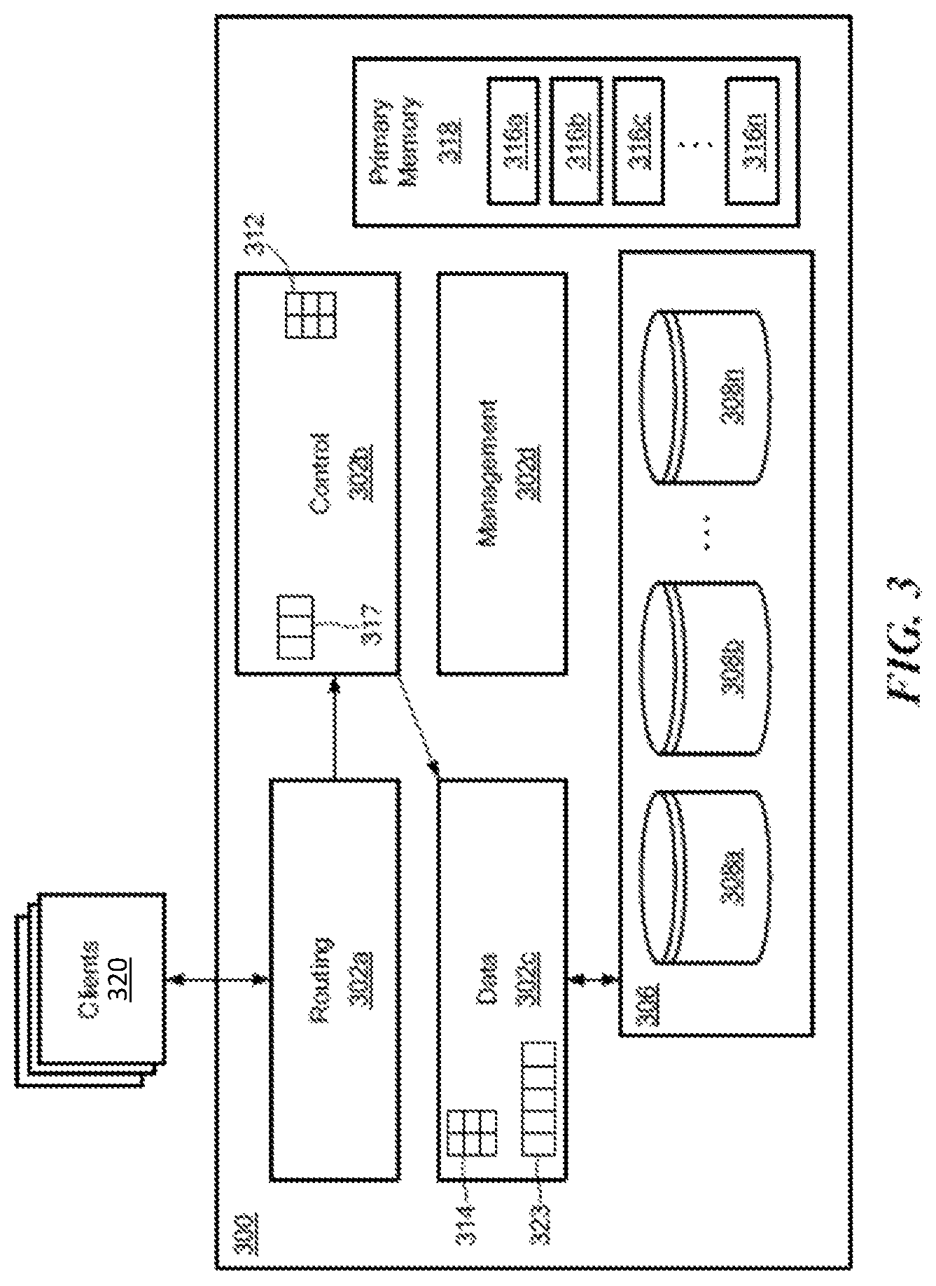
FIG. 3 shows a storage system 300 according to an illustrative embodiment of the disclosure. The storage system 300 may be the same as or similar to a node within the distributed storage system of FIG. 1A. The storage system 300 may include a plurality of modules 302a-302d (generally denoted 302 herein), a storage array 306 comprising a plurality of storage devices 308a . . . 308n (generally denoted 308 herein), and a primary memory 318. In some embodiments, the storage devices 308 may be provided as solid-state devices (SSDs).
As described further herein, the storage system 300 also can include a C (also called logical) cache 317 and a D (also called physical) cache 323. The C cache 317 and/or the D cache 323 can, in certain embodiments, be physical devices configured to store certain data so that future requests for that data can be served faster. Although the C cache 317 and D cache 323 are shown as being part of the storage system, it is understood that the C cache 317 and/or D cache 323 can be located anywhere such that they are accessible quickly to the storage system. Data that is stored within a cache might include data values that have been computed earlier or duplicates of original values that are stored elsewhere. If the requested data is contained in the cache (herein referred to as a cache hit), this request can be served by simply reading the cache, which is comparatively faster than going to other types of memory. On the other hand, if the requested data is not contained in the cache (herein referred to as a cache miss), the data may have to be to be recomputed or fetched from its original storage location, which is comparatively slower. Hence, the greater the number of requests that can be served from the cache, the faster the overall system performance becomes.
The primary memory 318 can be any type of memory having access times that are faster compared to the storage devices 308. In some embodiments, primary memory 318 may be provided as dynamic random-access memory (DRAM). In certain embodiments, primary memory 318 may be provided as synchronous DRAM (SDRAM). In one embodiment, primary memory 318 may be provided as double data rate SDRAM (DDR SDRAM), such as DDR3 SDRAM.
As described above, the control subsystem 302b may be configured to maintain a mapping between I/O addresses associated with data and the corresponding chunk hashes. As shown in FIG. 3, this mapping may be maintained using a data structure 312, referred to herein as an "I/O address to chunk hash mapping table" or "A2H table," (also known as A.fwdarw.H table) according to some embodiments. In one embodiment, I/O addresses may be logical addresses used by clients 320 to access data within the storage system 300.
As also described above, the data subsystem 302c may be configured to maintain a mapping between chunk hashes and physical storage addresses (i.e., storage locations within the storage array 306 and/or within individual storage devices 308). This mapping may be maintained using a data structure 314, referred to herein as a "hash to physical address mapping table" or "H2P table," or "H.fwdarw.P table," according to some embodiments, where this table, in certain embodiments, includes information similar to that of the aforementioned HMD (hash metadata) and PL (physical layout) tables. In certain embodiments, as described, for example, in the incorporated by reference patents, there also may be a mapping referred to as the H2D or H.fwdarw.D table, where D stands for disk physical layout. In certain embodiments, the H2P table is maintained to route data with different hashes to different D modules. The data subsystem 302c may be also be configured to read and write data from/to the storage array 306 (and/or to individual storage devices 308 therein).
As described above, in a content addressable storage system, data is stored in blocks, for example 16 KB, 8 KB, 4 KB, etc., where each block has a universally unique large hash signature, for example of 20 bytes, which can be saved to disk, e.g., Flash memory. As described herein, hash signatures may be accessed by small in-memory handles (referred to herein as short hash handles, hash handles, or short hashes), for example of 6 bytes. These short hashes may be unique to each volume/array, but not necessarily unique across volumes/arrays. Additional information relating to hash-based replication, computation of hashes, generation and use of short hash handles can be found in U.S. Pat. No. 9,378,106 ("Hash Based Replication"); U.S. Pat. No. 9,208,162 ("Generating a Short Hash Handle") and U.S. Pat. No. 9,396,243 ("Hash-Based Replication Using Short Hash Handle and Identity Bit"), each of which is hereby incorporated by reference.
In embodiments, address to hash mapping (A2H) maps an address inside a volume to the short hash value of its data. In embodiments, meta data can include for each address the hash value of the content. If the basis for deduplication is 16 KB, then the meta data holds for each address the short hash value of the data to which the address points. In cases where access to the volume is in larger chunks than the size of the basic hash value, the meta data for the address space can be readily cached.
As also noted above, hash to physical disk locations can include for each hash key (e.g., 6 bytes) the location on the disk, and the reference count. Where a storage system uses hash keys of 6 bytes, there may be collisions of data generating the same hash. If there is a collision, a new hash key from a different hash address space is generated for the data when the data is written. This means that the hash to physical disk location table may search for a hash value every time a new write arrives. If the write has the same hash value, there is a need to check the long hash value, and verify if there is a hash collision, or whether it is actually the same data. This means that during every write if the hash to physical disk location table is not in the system memory, there may a need to fetch the meta data of the hash from the disk to verify if such a hash exists. It will be appreciated that meta data structures may consume most of system memory, e.g., DRAM, in the storage system, so that the meta data limits the total size of the storage system.
FIG. 4 shows an example control or C module address to hash (A2H) mapping 400. As can be seen, as data blocks arrive, the content for the address is hashed to generate H1, H2, H3, H4, H5, as shown. It should be noted that H1 appears twice and is deduplicated. The D-module includes a hash to physical (H2P) mapping showing the physical offset of the data along with a reference count indicative of how many times a given hash value occurs. It will be appreciated that a particular hash value having a high reference count will likely be accessed more often than hash values having a low reference count. In embodiments, a reference count is incremented each time the hash value is generated in a volume. Thus, higher reference count hash values may be preferred for placement in D cache over low reference count hash values. It can be seen that the physical offset corresponds to the order in which a unique hash value is generated. For example, H3 is shown with an offset value of 2 since a second H1 value was deduplicated.
Modern storage systems, such as XtremIO, leverage flash drives to provide fast reliable de-duplicated storage. One of the challenges of a block based inline deduplication storage system is the fact that they use block aligned deduplication, which is less effective than byte aligned de duplication used by secondary storage arrays like data domain. For block storage it is more difficult to create byte aligned deduplication as IOs arrive in blocks, and it is hard to chunk the data correctly compared to a file system. Chunking refers to a process of splitting a file into pieces called chunks. In data deduplication applications, the process of chunking facilitates duplicate detection performance of the system.
A deduplication storage system, such as XtremIO has two layers for accessing the volume data. As described above, there is a layer mapping from address in the volume to the hash value of the data, and a second layer mapping from the hash value to a location on the disk. The address to hash mapping maps an address inside a volume to the hash value of its data. The metadata includes for each address the hash value of the content. If the basic use of deduplication is 16 KB, then the metadata holds for each address the short hash value (6 bytes) of the data the address points to. In many cases, access to the volume is in larger chunks than the size of the basic hash value. This means that the metadata for the address space can be easily cached, and standard prefetching algorithms work efficiently.
The hash to physical disk location includes for each hash key (6 bytes) the location on the disk and the reference count. Since the system is architected to keep hash keys of 6 bytes, there may be collision of data generating the same hash, if there is a collision a new hash key from a different hash address space is generated for that data, when the data is written. This means that the hash to physical disk location table, must search for a hash value every time a new write arrives, if the write has the same hash value, there is a need to check the long hash value, and verify if there is a hash collision, or it is actually the same data. This means that during every write if the table is not in the system memory, there is a need to fetch the meta data of the hash from the disk and verify if such hash exists.
Many systems today use a file system over the block devices that a block storage exposes. A file system element is a file which is mapped to a list of blocks. In many cases there are files having many parts of data being identical. One good example is a large customer that generates very large video files, and the files are identical except that each video has embedded subtitles which are part of the video. As there may be many countries to which the high quality video is targeted, this means that there is a lot of duplications in the data. The differences in the subtitles cause a drift in the block alignment between the video resulting in little or no deduplication. A byte aligned deduplication system can manage such assignment problems much better than block level deduplication and achieve effective deduplication ratios.
Block aligned deduplication systems typically support compression, which means trailing zeros will have little impact.
Embodiments described herein provide a dual-level deduplication system. In certain cases, an enterprise can utilize different types of storage systems to form a complete data storage environment. In one arrangement, the enterprise can utilize both a block based storage system and a file based storage hardware, such as a VNX.TM. or VNXe.TM. system (produced by EMC Corporation, Hopkinton, Mass.). In such an arrangement, typically the file based storage hardware operates as a front-end to the block based storage system such that the file based storage hardware and the block based storage system form a unified storage system.
Turning now to FIG. 5, the system 500 includes a file system 502 communicatively coupled to a backend deduplication block storage system 504. The file system 502 includes a file system driver 506, which creates a modified representation of its files. This modified representation of the files enables the backend deduplication system 504 to have a higher deduplication ratio, with minor performance effect.
The file system driver 506 may run on in any file system that utilizes the deduplicated block storage system 504 as a background storage. The file system 502 includes a number of files 508. Each of the files 508 in the file system has two parts: the file data (file contents) 510 and the metadata 512 describing the file structure of the respective file.
Each original file is chunked into multiple pieces (portions) 514 using a variable length chunking algorithm, which may be byte aligned. It is understood that the variable length chunking algorithm can be alternatively bit aligned. At the end of each chunk the system will put trailing zeros until the end of the block (i.e., pad with block until the size of the chunk is a multiple of the block size of the deduplicated block storage), e.g., in XtremIO the deduplicated block storage is 16 KB. The metadata 512 for each file will include the list of locations where the file was chunked.
The chunk size for files can be larger than the chunks for the block deduplication to allow smaller metadata files. Since the chunking algorithm is deterministic, the system can verify if a location is a place for chunking without the metadata indicating this. However, the metadata is needed to be able to access the file randomly.
The modified file system driver 506 will hide the metadata file and allow access only to the data files, leveraging the metadata files to allow random access. The block storage will have correct alignment of the data in the blocks, and the effect of the trailing zeros will be minimal on the space as compression, such as run-length encoding (RLE) and Lempel Ziv (LZ) will reduce the space used by the relevant blocks.
An example technique for two data files 602 and 608 is shown in FIG. 6. The example shown in FIG. 6 assumes that a block size is four characters. Turning to FIG. 6, the first file 602 is broken down into six blocks 604 (four characters each). The second file 608 is broken down into six blocks 610, also having four characters per block.
The deduplication ratio will be zero, but if chunked correctly and zeros are added in the proper place, the deduplication will be more effective.
The first file 602 will result in chunked blocks 606 having regular block alignment (i.e., no change from the blocks 604). The second file 608 will result in chunked blocks 612. The block storage will not deduplicate between ABCD ABCZ and D000 but the rest of the data will be deduplicated, and the three zeros added after the `D` will be effectively compressed.
Turning now to FIG. 7, a flow diagram of a process 700 for implementing the embodiments herein will now be described. In block 702, the process 700 accesses a file in the file system. This may be implemented by the file system driver. In block 704, the process 700 breaks the file down into multiple blocks. This step may be implemented by the file system driver.
In block 706, the process 700 chunks the blocks. At the end of each block the process 700 adds trailing zeros until the size of the chunk is a multiple of a block size of the deduplication block storage. This step may be implemented by the file system driver via a variable length chunking algorithm. The resulting chunked files may be stored in the file system.
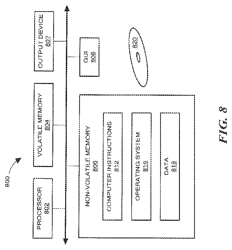
FIG. 8 shows an exemplary computer 800 (e.g., physical or virtual) that can perform at least part of the processing described herein. The computer 800 includes a processor 802, a volatile memory 804, a non-volatile memory 806 (e.g., hard disk or flash), an output device 807 and a graphical user interface (GUI) 808 (e.g., a mouse, a keyboard, a display, for example). The non-volatile memory 806 stores computer instructions 812, an operating system 816 and data 818. In one example, the computer instructions 812 are executed by the processor 802 out of volatile memory 804. In one embodiment, an article 820 comprises non-transitory computer-readable instructions.
Processing may be implemented in hardware, software, or a combination of the two. Processing may be implemented in computer programs executed on programmable computers/machines that each includes a processor, a storage medium or other article of manufacture that is readable by the processor (including volatile and non-volatile memory and/or storage elements), at least one input device, and one or more output devices. Program code may be applied to data entered using an input device to perform processing and to generate output information.
The system can perform processing, at least in part, via a computer program product, (e.g., in a machine-readable storage device), for execution by, or to control the operation of, data processing apparatus (e.g., a programmable processor, a computer, or multiple computers). Each such program may be implemented in a high level procedural or object-oriented programming language to communicate with a computer system. However, the programs may be implemented in assembly or machine language. The language may be a compiled or an interpreted language and it may be deployed in any form, including as a stand-alone program or as a module, component, subroutine, or other unit suitable for use in a computing environment. A computer program may be deployed to be executed on one computer or on multiple computers at one site or distributed across multiple sites and interconnected by a communication network. A computer program may be stored on a storage medium or device (e.g., CD-ROM, hard disk, or magnetic diskette) that is readable by a general or special purpose programmable computer for configuring and operating the computer when the storage medium or device is read by the computer. Processing may also be implemented as a machine-readable storage medium, configured with a computer program, where upon execution, instructions in the computer program cause the computer to operate.
Processing may be performed by one or more programmable processors executing one or more computer programs to perform the functions of the system. All or part of the system may be implemented as, special purpose logic circuitry (e.g., an FPGA (field programmable gate array) and/or an ASIC (application-specific integrated circuit)).
Having described exemplary embodiments of the invention, it will now become apparent to one of ordinary skill in the art that other embodiments incorporating their concepts may also be used. The embodiments contained herein should not be limited to disclosed embodiments but rather should be limited only by the spirit and scope of the appended claims. All publications and references cited herein are expressly incorporated herein by reference in their entirety.
Elements of different embodiments described herein may be combined to form other embodiments not specifically set forth above. Various elements, which are described in the context of a single embodiment, may also be provided separately or in any suitable subcombination. Other embodiments not specifically described herein are also within the scope of the following claims.
* * * * *
D00000
D00001
D00002
D00003
D00004
D00005
D00006
D00007
D00008
D00009
XML
uspto.report is an independent third-party trademark research tool that is not affiliated, endorsed, or sponsored by the United States Patent and Trademark Office (USPTO) or any other governmental organization. The information provided by uspto.report is based on publicly available data at the time of writing and is intended for informational purposes only.
While we strive to provide accurate and up-to-date information, we do not guarantee the accuracy, completeness, reliability, or suitability of the information displayed on this site. The use of this site is at your own risk. Any reliance you place on such information is therefore strictly at your own risk.
All official trademark data, including owner information, should be verified by visiting the official USPTO website at www.uspto.gov. This site is not intended to replace professional legal advice and should not be used as a substitute for consulting with a legal professional who is knowledgeable about trademark law.