Temporal configuration of a motion sensor in an implantable medical device
Kane , et al.
U.S. patent number 10,709,892 [Application Number 15/935,806] was granted by the patent office on 2020-07-14 for temporal configuration of a motion sensor in an implantable medical device. This patent grant is currently assigned to CARDIAC PACEMAKERS, INC.. The grantee listed for this patent is CARDIAC PACEMAKERS, INC.. Invention is credited to Ron A. Balczewski, Benjamin J. Haasl, John D. Hatlestad, Paul Huelskamp, Michael J. Kane, William J. Linder, Keith R. Maile, Bin Mi, Allan Charles Shuros.


View All Diagrams
| United States Patent | 10,709,892 |
| Kane , et al. | July 14, 2020 |
Temporal configuration of a motion sensor in an implantable medical device
Abstract
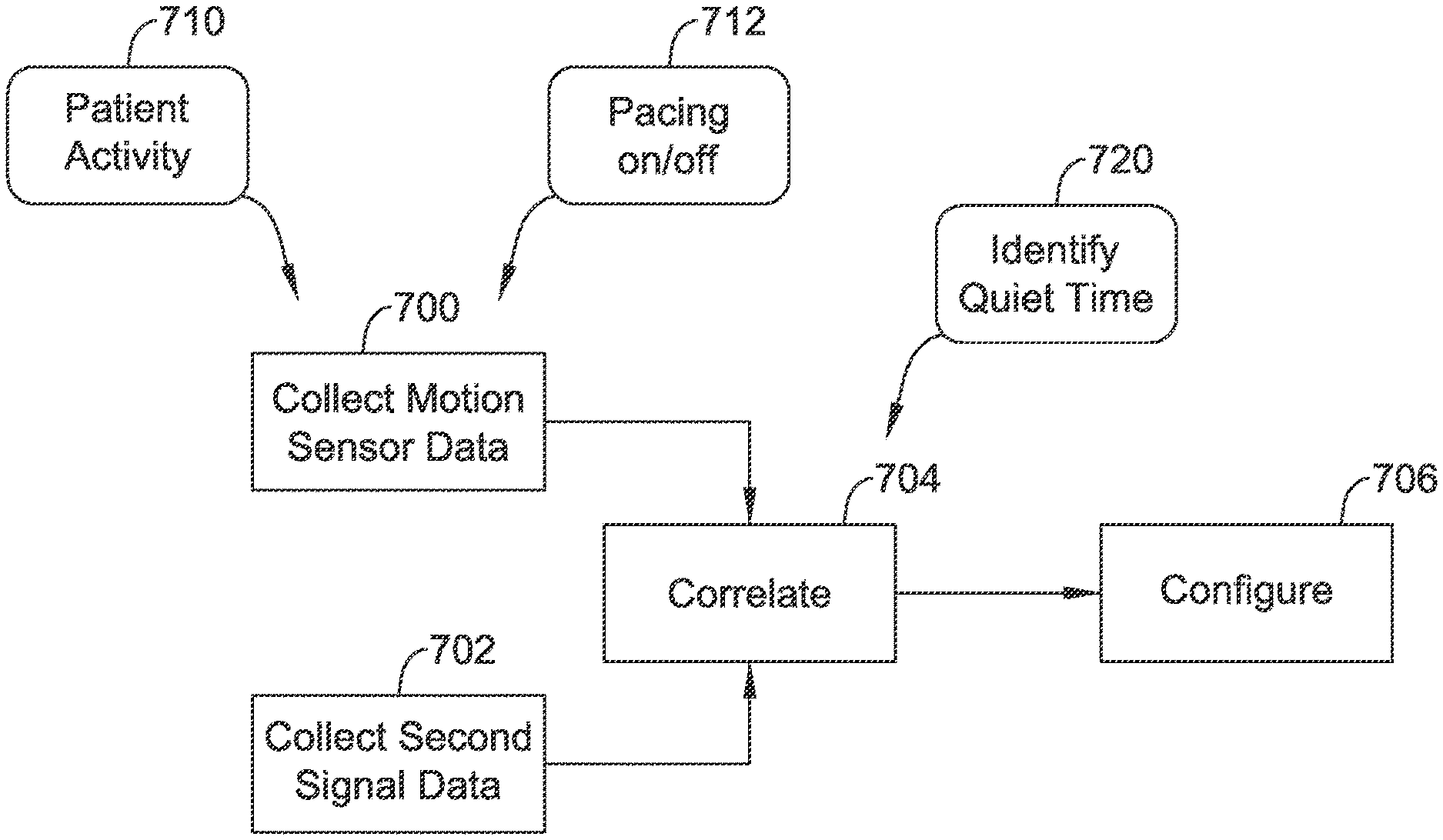
Methods and devices for configuring the use of a motion sensor in an implantable cardiac device. The electrical signals of the patient's heart are observed and may be correlated to the physical motion of the heart as detected by the motion sensor of the implantable cardiac device in order to facilitate temporal configuration of motion sensor data collection that avoids detecting cardiac motion in favor of overall motion of the patient.
| Inventors: | Kane; Michael J. (St. Paul, MN), Linder; William J. (Golden Valley, MN), Haasl; Benjamin J. (Forest Lake, MN), Huelskamp; Paul (St. Paul, MN), Maile; Keith R. (New Brighton, MN), Balczewski; Ron A. (Bloomington, MN), Mi; Bin (Arden Hills, MN), Hatlestad; John D. (Maplewood, MN), Shuros; Allan Charles (St. Paul, MN) | ||||||||||
|---|---|---|---|---|---|---|---|---|---|---|---|
| Applicant: |
|
||||||||||
| Assignee: | CARDIAC PACEMAKERS, INC. (St.
Paul, MN) |
||||||||||
| Family ID: | 56852417 | ||||||||||
| Appl. No.: | 15/935,806 | ||||||||||
| Filed: | March 26, 2018 |
Prior Publication Data
| Document Identifier | Publication Date | |
|---|---|---|
| US 20180207426 A1 | Jul 26, 2018 | |
Related U.S. Patent Documents
| Application Number | Filing Date | Patent Number | Issue Date | ||
|---|---|---|---|---|---|
| 15243524 | Aug 22, 2016 | 9956414 | |||
| 62210882 | Aug 27, 2015 | ||||
| Current U.S. Class: | 1/1 |
| Current CPC Class: | A61B 5/6869 (20130101); A61N 1/36542 (20130101); A61N 1/3756 (20130101); A61B 5/0452 (20130101); A61N 1/371 (20130101); A61B 5/1118 (20130101); A61N 1/3684 (20130101); A61B 5/686 (20130101); A61B 5/1107 (20130101); A61B 2562/0219 (20130101); A61N 1/37205 (20130101); A61N 1/36578 (20130101) |
| Current International Class: | A61N 1/365 (20060101); A61B 5/0452 (20060101); A61N 1/375 (20060101); A61B 5/00 (20060101); A61B 5/11 (20060101); A61N 1/37 (20060101); A61N 1/368 (20060101); A61N 1/372 (20060101) |
References Cited [Referenced By]
U.S. Patent Documents
| 3835864 | September 1974 | Rasor et al. |
| 3943936 | March 1976 | Rasor et al. |
| 4142530 | March 1979 | Wittkampf |
| 4151513 | April 1979 | Menken et al. |
| 4157720 | June 1979 | Greatbatch |
| RE30366 | August 1980 | Rasor et al. |
| 4250884 | February 1981 | Hartlaub et al. |
| 4256115 | March 1981 | Bilitch |
| 4263919 | April 1981 | Levin |
| 4310000 | January 1982 | Lindemans |
| 4312354 | January 1982 | Walters |
| 4323081 | April 1982 | Wiebusch |
| 4357946 | November 1982 | Dutcher et al. |
| 4365639 | December 1982 | Goldreyer |
| 4440173 | April 1984 | Kludziak et al. |
| 4476868 | October 1984 | Thompson |
| 4522208 | June 1985 | Buffet |
| 4556063 | December 1985 | Thompson et al. |
| 4562841 | January 1986 | Brockway et al. |
| 4593702 | June 1986 | Kepski et al. |
| 4593955 | June 1986 | Leiber |
| 4630611 | December 1986 | King |
| 4635639 | January 1987 | Hakala et al. |
| 4674508 | June 1987 | DeCote |
| 4712554 | December 1987 | Garson |
| 4729376 | March 1988 | DeCote |
| 4754753 | July 1988 | King |
| 4759366 | July 1988 | Callaghan |
| 4787389 | November 1988 | Tarjan |
| 4793353 | December 1988 | Borkan |
| 4819662 | April 1989 | Heil et al. |
| 4858610 | August 1989 | Callaghan et al. |
| 4886064 | December 1989 | Strandberg |
| 4928688 | May 1990 | Mower |
| 4967746 | November 1990 | Vandegriff |
| 4987897 | January 1991 | Funke |
| 4989602 | February 1991 | Sholder et al. |
| 5012806 | May 1991 | De Bellis |
| 5036849 | August 1991 | Hauck et al. |
| 5058581 | October 1991 | Silvian |
| 5078134 | January 1992 | Heilman et al. |
| 5109845 | May 1992 | Yuuchi et al. |
| 5113859 | May 1992 | Funke |
| 5117824 | June 1992 | Keimel et al. |
| 5127401 | July 1992 | Grevious et al. |
| 5133353 | July 1992 | Hauser |
| 5144950 | September 1992 | Stoop et al. |
| 5170784 | December 1992 | Ramon et al. |
| 5179945 | January 1993 | Van Hofwegen et al. |
| 5193539 | March 1993 | Schulman et al. |
| 5193540 | March 1993 | Schulman et al. |
| 5241961 | September 1993 | Henry |
| 5243977 | September 1993 | Trabucco et al. |
| 5269326 | December 1993 | Verrier |
| 5284136 | February 1994 | Hauck et al. |
| 5300107 | April 1994 | Stokes et al. |
| 5301677 | April 1994 | Hsung |
| 5312439 | May 1994 | Loeb |
| 5313953 | May 1994 | Yomtov et al. |
| 5314459 | May 1994 | Swanson et al. |
| 5318597 | June 1994 | Hauck et al. |
| 5324316 | June 1994 | Schulman et al. |
| 5331966 | July 1994 | Bennett et al. |
| 5334222 | August 1994 | Salo et al. |
| 5342408 | August 1994 | deCoriolis et al. |
| 5372606 | December 1994 | Lang et al. |
| 5376106 | December 1994 | Stahmann et al. |
| 5383915 | January 1995 | Adams |
| 5388578 | February 1995 | Yomtov et al. |
| 5404877 | April 1995 | Nolan et al. |
| 5405367 | April 1995 | Schulman et al. |
| 5411031 | May 1995 | Yomtov |
| 5411525 | May 1995 | Swanson et al. |
| 5411535 | May 1995 | Fujii et al. |
| 5456691 | October 1995 | Snell |
| 5466246 | November 1995 | Silvian |
| 5468254 | November 1995 | Hahn et al. |
| 5522866 | June 1996 | Fernald |
| 5540727 | July 1996 | Tockman et al. |
| 5545186 | August 1996 | Olson et al. |
| 5545202 | August 1996 | Dahl et al. |
| 5591214 | January 1997 | Lu |
| 5620466 | April 1997 | Haefner et al. |
| 5634938 | June 1997 | Swanson et al. |
| 5662688 | September 1997 | Haefner et al. |
| 5674259 | October 1997 | Gray |
| 5683426 | November 1997 | Greenhut et al. |
| 5683432 | November 1997 | Goedeke et al. |
| 5720770 | February 1998 | Nappholz et al. |
| 5728154 | March 1998 | Crossett et al. |
| 5741314 | April 1998 | Daly et al. |
| 5741315 | April 1998 | Lee et al. |
| 5752976 | May 1998 | Duffin et al. |
| 5752977 | May 1998 | Grevious et al. |
| 5755736 | May 1998 | Gillberg et al. |
| 5759199 | June 1998 | Snell et al. |
| 5774501 | June 1998 | Halpern et al. |
| 5792202 | August 1998 | Rueter |
| 5792203 | August 1998 | Schroeppel |
| 5792205 | August 1998 | Alt et al. |
| 5792208 | August 1998 | Gray |
| 5814089 | September 1998 | Stokes et al. |
| 5827216 | October 1998 | Igo et al. |
| 5836985 | November 1998 | Rostami et al. |
| 5836987 | November 1998 | Baumann et al. |
| 5842977 | December 1998 | Lesho et al. |
| 5855593 | January 1999 | Olson et al. |
| 5873894 | February 1999 | Vandegriff et al. |
| 5891184 | April 1999 | Lee et al. |
| 5897586 | April 1999 | Molina |
| 5899876 | May 1999 | Flower |
| 5899928 | May 1999 | Sholder et al. |
| 5919214 | July 1999 | Ciciarelli et al. |
| 5935078 | August 1999 | Feierbach |
| 5941906 | August 1999 | Barreras, Sr. et al. |
| 5954757 | September 1999 | Gray |
| 5978713 | November 1999 | Prutchi et al. |
| 5991660 | November 1999 | Goyal |
| 5999848 | December 1999 | Gord et al. |
| 5999857 | December 1999 | Weijand et al. |
| 6026320 | February 2000 | Carlson et al. |
| 6044298 | March 2000 | Salo et al. |
| 6044300 | March 2000 | Gray |
| 6055454 | April 2000 | Heemels |
| 6073050 | June 2000 | Griffith |
| 6076016 | June 2000 | Feierbach |
| 6080187 | June 2000 | Alt et al. |
| 6083248 | July 2000 | Thompson |
| 6106551 | August 2000 | Crossett et al. |
| 6115636 | September 2000 | Ryan |
| 6141581 | October 2000 | Olson et al. |
| 6141588 | October 2000 | Cox et al. |
| 6141592 | October 2000 | Pauly |
| 6144879 | November 2000 | Gray |
| 6162195 | December 2000 | Igo et al. |
| 6164284 | December 2000 | Schulman et al. |
| 6167310 | December 2000 | Grevious |
| 6208894 | March 2001 | Schulman et al. |
| 6211799 | April 2001 | Post et al. |
| 6221011 | April 2001 | Bardy |
| 6240316 | May 2001 | Richmond et al. |
| 6240317 | May 2001 | Villaseca et al. |
| 6256534 | July 2001 | Dahl |
| 6259947 | July 2001 | Olson et al. |
| 6266558 | July 2001 | Gozani et al. |
| 6266567 | July 2001 | Ishikawa et al. |
| 6270457 | August 2001 | Bardy |
| 6272377 | August 2001 | Sweeney et al. |
| 6277072 | August 2001 | Bardy |
| 6280380 | August 2001 | Bardy |
| 6285907 | September 2001 | Kramer et al. |
| 6292698 | September 2001 | Duffin et al. |
| 6295473 | September 2001 | Rosar |
| 6298271 | October 2001 | Weijand |
| 6312378 | November 2001 | Bardy |
| 6315721 | November 2001 | Schulman et al. |
| 6336903 | January 2002 | Bardy |
| 6345202 | February 2002 | Richmond et al. |
| 6351667 | February 2002 | Godie |
| 6351669 | February 2002 | Hartley et al. |
| 6353759 | March 2002 | Hartley et al. |
| 6358203 | March 2002 | Bardy |
| 6361780 | March 2002 | Ley et al. |
| 6368284 | April 2002 | Bardy |
| 6371922 | April 2002 | Baumann et al. |
| 6398728 | June 2002 | Bardy |
| 6400982 | June 2002 | Sweeney et al. |
| 6400990 | June 2002 | Silvian |
| 6409674 | June 2002 | Brockway et al. |
| 6411848 | June 2002 | Kramer et al. |
| 6424865 | July 2002 | Ding |
| 6434429 | August 2002 | Kraus et al. |
| 6438410 | August 2002 | Hsu et al. |
| 6438417 | August 2002 | Rockwell et al. |
| 6438421 | August 2002 | Stahmann et al. |
| 6440066 | August 2002 | Bardy |
| 6441747 | August 2002 | Khair et al. |
| 6442426 | August 2002 | Kroll |
| 6442432 | August 2002 | Lee |
| 6443891 | September 2002 | Grevious |
| 6445953 | September 2002 | Bulkes et al. |
| 6453200 | September 2002 | Koslar |
| 6459929 | October 2002 | Hopper et al. |
| 6470215 | October 2002 | Kraus et al. |
| 6471645 | October 2002 | Warkentin et al. |
| 6480745 | November 2002 | Nelson et al. |
| 6487443 | November 2002 | Olson et al. |
| 6490487 | December 2002 | Kraus et al. |
| 6507755 | January 2003 | Gozani et al. |
| 6507759 | January 2003 | Prutchi et al. |
| 6512940 | January 2003 | Brabec et al. |
| 6522915 | February 2003 | Ceballos et al. |
| 6526311 | February 2003 | Begemann |
| 6542775 | April 2003 | Ding et al. |
| 6553258 | April 2003 | Stahmann et al. |
| 6561975 | May 2003 | Pool et al. |
| 6564807 | May 2003 | Schulman et al. |
| 6574506 | June 2003 | Kramer et al. |
| 6584352 | June 2003 | Combs et al. |
| 6597948 | July 2003 | Rockwell et al. |
| 6597951 | July 2003 | Kramer et al. |
| 6622046 | September 2003 | Fraley et al. |
| 6628985 | September 2003 | Sweeney et al. |
| 6647292 | November 2003 | Bardy et al. |
| 6666844 | December 2003 | Igo et al. |
| 6689117 | February 2004 | Sweeney et al. |
| 6690959 | February 2004 | Thompson |
| 6704602 | March 2004 | Berg et al. |
| 6718212 | April 2004 | Parry et al. |
| 6721597 | April 2004 | Bardy et al. |
| 6738670 | May 2004 | Almendinger et al. |
| 6749566 | June 2004 | Russ |
| 6758810 | July 2004 | Lebel et al. |
| 6763269 | July 2004 | Cox |
| 6778860 | August 2004 | Ostroff et al. |
| 6788971 | September 2004 | Sloman et al. |
| 6788974 | September 2004 | Bardy et al. |
| 6804558 | October 2004 | Haller et al. |
| 6847844 | January 2005 | Sun et al. |
| 6871095 | March 2005 | Stahmann et al. |
| 6878112 | April 2005 | Linberg et al. |
| 6885889 | April 2005 | Chinchoy |
| 6892094 | May 2005 | Ousdigian et al. |
| 6897788 | May 2005 | Khair et al. |
| 6904315 | June 2005 | Panken et al. |
| 6922592 | July 2005 | Thompson et al. |
| 6931282 | August 2005 | Esler |
| 6934585 | August 2005 | Schloss et al. |
| 6957107 | October 2005 | Rogers et al. |
| 6978176 | December 2005 | Lattouf |
| 6985773 | January 2006 | Von Arx et al. |
| 7003350 | February 2006 | Denker et al. |
| 7006864 | February 2006 | Echt et al. |
| 7013178 | March 2006 | Reinke et al. |
| 7027871 | April 2006 | Burnes et al. |
| 7050849 | May 2006 | Echt et al. |
| 7060031 | June 2006 | Webb et al. |
| 7063693 | June 2006 | Guenst |
| 7082336 | July 2006 | Ransbury et al. |
| 7085606 | August 2006 | Flach et al. |
| 7110824 | September 2006 | Amundson et al. |
| 7120504 | October 2006 | Osypka |
| 7139613 | November 2006 | Reinke et al. |
| 7142912 | November 2006 | Wagner et al. |
| 7146225 | December 2006 | Guenst et al. |
| 7146226 | December 2006 | Lau et al. |
| 7149581 | December 2006 | Goedeke |
| 7149588 | December 2006 | Lau et al. |
| 7158839 | January 2007 | Lau |
| 7162307 | January 2007 | Patrias |
| 7164952 | January 2007 | Lau et al. |
| 7177700 | February 2007 | Cox |
| 7181505 | February 2007 | Haller et al. |
| 7184830 | February 2007 | Echt et al. |
| 7186214 | March 2007 | Ness |
| 7191015 | March 2007 | Lamson et al. |
| 7200437 | April 2007 | Nabutovsky et al. |
| 7200439 | April 2007 | Zdeblick et al. |
| 7206423 | April 2007 | Feng et al. |
| 7209790 | April 2007 | Thompson et al. |
| 7212871 | May 2007 | Morgan |
| 7226440 | June 2007 | Gelfand et al. |
| 7228183 | June 2007 | Sun et al. |
| 7236821 | June 2007 | Cates et al. |
| 7236829 | June 2007 | Farazi et al. |
| 7254448 | August 2007 | Almendinger et al. |
| 7260436 | August 2007 | Kilgore et al. |
| 7270669 | September 2007 | Sra |
| 7272448 | September 2007 | Morgan et al. |
| 7277755 | October 2007 | Falkenberg et al. |
| 7280872 | October 2007 | Mosesov et al. |
| 7288096 | October 2007 | Chin |
| 7289847 | October 2007 | Gill et al. |
| 7289852 | October 2007 | Helfinstine et al. |
| 7289853 | October 2007 | Campbell et al. |
| 7289855 | October 2007 | Nghiem et al. |
| 7302294 | November 2007 | Kamath et al. |
| 7305266 | December 2007 | Kroll |
| 7310556 | December 2007 | Bulkes |
| 7319905 | January 2008 | Morgan et al. |
| 7333853 | February 2008 | Mazar et al. |
| 7336994 | February 2008 | Hettrick et al. |
| 7347819 | March 2008 | Lebel et al. |
| 7366572 | April 2008 | Heruth et al. |
| 7373207 | May 2008 | Lattouf |
| 7384403 | June 2008 | Sherman |
| 7386342 | June 2008 | Falkenberg et al. |
| 7392090 | June 2008 | Sweeney et al. |
| 7406105 | July 2008 | DelMain et al. |
| 7406349 | July 2008 | Seeberger et al. |
| 7410497 | August 2008 | Hastings et al. |
| 7425200 | September 2008 | Brockway et al. |
| 7433739 | October 2008 | Salys et al. |
| 7496409 | February 2009 | Greenhut et al. |
| 7496410 | February 2009 | Heil |
| 7502652 | March 2009 | Gaunt et al. |
| 7512448 | March 2009 | Malick et al. |
| 7515969 | April 2009 | Tockman et al. |
| 7526342 | April 2009 | Chin et al. |
| 7529589 | May 2009 | Williams et al. |
| 7532933 | May 2009 | Hastings et al. |
| 7536222 | May 2009 | Bardy et al. |
| 7539541 | May 2009 | Quiles et al. |
| 7544197 | June 2009 | Kelsch et al. |
| 7558631 | July 2009 | Cowan et al. |
| 7565195 | July 2009 | Kroll et al. |
| 7584002 | September 2009 | Burnes et al. |
| 7590455 | September 2009 | Heruth et al. |
| 7606621 | October 2009 | Brisken et al. |
| 7610088 | October 2009 | Chinchoy |
| 7610092 | October 2009 | Cowan et al. |
| 7610099 | October 2009 | Almendinger et al. |
| 7610104 | October 2009 | Kaplan et al. |
| 7616991 | November 2009 | Mann et al. |
| 7617001 | November 2009 | Penner et al. |
| 7617007 | November 2009 | Williams et al. |
| 7630767 | December 2009 | Poore et al. |
| 7634313 | December 2009 | Kroll et al. |
| 7637867 | December 2009 | Zdeblick |
| 7640060 | December 2009 | Zdeblick |
| 7647109 | January 2010 | Hastings et al. |
| 7650186 | January 2010 | Hastings et al. |
| 7657311 | February 2010 | Bardy et al. |
| 7668596 | February 2010 | Von Arx et al. |
| 7691047 | April 2010 | Ferrari |
| 7702392 | April 2010 | Echt et al. |
| 7713194 | May 2010 | Zdeblick |
| 7713195 | May 2010 | Zdeblick |
| 7729783 | June 2010 | Michels et al. |
| 7734333 | June 2010 | Ghanem et al. |
| 7734343 | June 2010 | Ransbury et al. |
| 7738958 | June 2010 | Zdeblick et al. |
| 7738964 | June 2010 | Von Arx et al. |
| 7742812 | June 2010 | Ghanem et al. |
| 7742816 | June 2010 | Masoud et al. |
| 7742822 | June 2010 | Masoud et al. |
| 7743151 | June 2010 | Vallapureddy et al. |
| 7747335 | June 2010 | Williams |
| 7751881 | July 2010 | Cowan et al. |
| 7758521 | July 2010 | Morris et al. |
| 7761150 | July 2010 | Ghanem et al. |
| 7761164 | July 2010 | Verhoef et al. |
| 7765001 | July 2010 | Echt et al. |
| 7769452 | August 2010 | Ghanem et al. |
| 7778699 | August 2010 | Ferrise et al. |
| 7792588 | September 2010 | Harding |
| 7797059 | September 2010 | Bornzin et al. |
| 7801596 | September 2010 | Fischell et al. |
| 7809438 | October 2010 | Echt et al. |
| 7840281 | November 2010 | Kveen et al. |
| 7844348 | November 2010 | Swoyer et al. |
| 7846088 | December 2010 | Ness |
| 7848815 | December 2010 | Brisken et al. |
| 7848823 | December 2010 | Drasler et al. |
| 7860455 | December 2010 | Fukumoto et al. |
| 7871433 | January 2011 | Lattouf |
| 7877136 | January 2011 | Moffitt et al. |
| 7877142 | January 2011 | Moaddeb et al. |
| 7881798 | February 2011 | Miesel et al. |
| 7881810 | February 2011 | Chitre et al. |
| 7890173 | February 2011 | Brisken et al. |
| 7890181 | February 2011 | Denzene et al. |
| 7890192 | February 2011 | Kelsch et al. |
| 7894894 | February 2011 | Stadler et al. |
| 7894907 | February 2011 | Cowan et al. |
| 7894910 | February 2011 | Cowan et al. |
| 7894915 | February 2011 | Chitre et al. |
| 7899537 | March 2011 | Kroll et al. |
| 7899541 | March 2011 | Cowan et al. |
| 7899542 | March 2011 | Cowan et al. |
| 7899554 | March 2011 | Williams et al. |
| 7901360 | March 2011 | Yang et al. |
| 7904170 | March 2011 | Harding |
| 7907993 | March 2011 | Ghanem et al. |
| 7920928 | April 2011 | Yang et al. |
| 7925343 | April 2011 | Min et al. |
| 7930040 | April 2011 | Kelsch et al. |
| 7937135 | May 2011 | Ghanem et al. |
| 7937148 | May 2011 | Jacobson |
| 7937161 | May 2011 | Hastings et al. |
| 7941214 | May 2011 | Kleckner et al. |
| 7945333 | May 2011 | Jacobson |
| 7946997 | May 2011 | Hubinette |
| 7949404 | May 2011 | Hill |
| 7949405 | May 2011 | Feher |
| 7953493 | May 2011 | Fowler et al. |
| 7962202 | June 2011 | Bhunia |
| 7974702 | July 2011 | Fain et al. |
| 7979136 | July 2011 | Young et al. |
| 7983753 | July 2011 | Severin |
| 7991467 | August 2011 | Markowitz et al. |
| 7991471 | August 2011 | Ghanem et al. |
| 7996087 | August 2011 | Cowan et al. |
| 8000791 | August 2011 | Sunagawa et al. |
| 8000807 | August 2011 | Morris et al. |
| 8001975 | August 2011 | DiSilvestro et al. |
| 8002700 | August 2011 | Ferek-Petric et al. |
| 8010209 | August 2011 | Jacobson |
| 8019419 | September 2011 | Panescu et al. |
| 8019434 | September 2011 | Quiles et al. |
| 8027727 | September 2011 | Freeberg |
| 8027729 | September 2011 | Sunagawa et al. |
| 8032219 | October 2011 | Neumann et al. |
| 8036743 | October 2011 | Savage et al. |
| 8046079 | October 2011 | Bange et al. |
| 8046080 | October 2011 | Von Arx et al. |
| 8050297 | November 2011 | DelMain et al. |
| 8050759 | November 2011 | Stegemann et al. |
| 8050774 | November 2011 | Kveen et al. |
| 8055345 | November 2011 | Li et al. |
| 8055350 | November 2011 | Roberts |
| 8060212 | November 2011 | Rios et al. |
| 8065018 | November 2011 | Haubrich et al. |
| 8073542 | December 2011 | Doerr |
| 8078278 | December 2011 | Penner |
| 8078283 | December 2011 | Cowan et al. |
| 8095123 | January 2012 | Gray |
| 8102789 | January 2012 | Rosar et al. |
| 8103359 | January 2012 | Reddy |
| 8103361 | January 2012 | Moser |
| 8112148 | February 2012 | Giftakis et al. |
| 8114021 | February 2012 | Robertson et al. |
| 8121680 | February 2012 | Falkenberg et al. |
| 8123684 | February 2012 | Zdeblick |
| 8126545 | February 2012 | Flach et al. |
| 8131334 | March 2012 | Lu et al. |
| 8140161 | March 2012 | Willerton et al. |
| 8150521 | April 2012 | Crowley et al. |
| 8160672 | April 2012 | Kim et al. |
| 8160702 | April 2012 | Mann et al. |
| 8160704 | April 2012 | Freeberg |
| 8165694 | April 2012 | Carbanaru et al. |
| 8175715 | May 2012 | Cox |
| 8180451 | May 2012 | Hickman et al. |
| 8185213 | May 2012 | Kveen et al. |
| 8187161 | May 2012 | Li et al. |
| 8204595 | June 2012 | Pianca et al. |
| 8204605 | June 2012 | Hastings et al. |
| 8209014 | June 2012 | Doerr |
| 8214043 | July 2012 | Matos |
| 8224244 | July 2012 | Kim et al. |
| 8233985 | July 2012 | Bulkes et al. |
| 8265748 | September 2012 | Liu et al. |
| 8265757 | September 2012 | Mass et al. |
| 8280521 | October 2012 | Haubrich et al. |
| 8285387 | October 2012 | Utsi et al. |
| 8290598 | October 2012 | Boon et al. |
| 8290600 | October 2012 | Hastings et al. |
| 8295939 | October 2012 | Jacobson |
| 8301254 | October 2012 | Mosesov et al. |
| 8315701 | November 2012 | Cowan et al. |
| 8315708 | November 2012 | Berthelsdorf et al. |
| 8321021 | November 2012 | Kisker et al. |
| 8321036 | November 2012 | Brockway et al. |
| 8332036 | December 2012 | Hastings et al. |
| 8335563 | December 2012 | Stessman |
| 8335568 | December 2012 | Heruth et al. |
| 8340750 | December 2012 | Prakash et al. |
| 8340780 | December 2012 | Hastings et al. |
| 8352025 | January 2013 | Jacobson |
| 8352028 | January 2013 | Wenger |
| 8352038 | January 2013 | Mao et al. |
| 8359098 | January 2013 | Lund et al. |
| 8364276 | January 2013 | Willis |
| 8369959 | February 2013 | Meskens |
| 8369962 | February 2013 | Abrahamson |
| 8380320 | February 2013 | Spital |
| 8386051 | February 2013 | Rys |
| 8391981 | March 2013 | Mosesov |
| 8391990 | March 2013 | Smith et al. |
| 8406874 | March 2013 | Liu et al. |
| 8406886 | March 2013 | Gaunt et al. |
| 8412352 | April 2013 | Griswold et al. |
| 8417340 | April 2013 | Goossen |
| 8417341 | April 2013 | Freeberg |
| 8423149 | April 2013 | Hennig |
| 8428722 | April 2013 | Verhoef et al. |
| 8433402 | April 2013 | Ruben et al. |
| 8433409 | April 2013 | Johnson et al. |
| 8433420 | April 2013 | Bange et al. |
| 8447412 | May 2013 | Dal Molin et al. |
| 8452413 | May 2013 | Young et al. |
| 8457740 | June 2013 | Osche |
| 8457742 | June 2013 | Jacobson |
| 8457761 | June 2013 | Wariar |
| 8478407 | July 2013 | Demmer et al. |
| 8478408 | July 2013 | Hastings et al. |
| 8478431 | July 2013 | Griswold et al. |
| 8504156 | August 2013 | Bonner et al. |
| 8509910 | August 2013 | Sowder et al. |
| 8515559 | August 2013 | Roberts et al. |
| 8527068 | September 2013 | Ostroff |
| 8532790 | September 2013 | Griswold |
| 8541131 | September 2013 | Lund et al. |
| 8543205 | September 2013 | Ostroff |
| 8547248 | October 2013 | Zdeblick et al. |
| 8548605 | October 2013 | Ollivier |
| 8554333 | October 2013 | Wu et al. |
| 8565878 | October 2013 | Allavatam et al. |
| 8565882 | October 2013 | Mates |
| 8565897 | October 2013 | Regnier et al. |
| 8571678 | October 2013 | Wang |
| 8577327 | November 2013 | Makdissi et al. |
| 8588926 | November 2013 | Moore et al. |
| 8612002 | December 2013 | Faltys et al. |
| 8615310 | December 2013 | Khairkhahan et al. |
| 8626294 | January 2014 | Sheldon et al. |
| 8634908 | January 2014 | Cowan |
| 8634912 | January 2014 | Bornzin et al. |
| 8634919 | January 2014 | Hou et al. |
| 8639335 | January 2014 | Peichel et al. |
| 8644934 | February 2014 | Hastings et al. |
| 8649859 | February 2014 | Smith et al. |
| 8670842 | March 2014 | Bornzin et al. |
| 8676319 | March 2014 | Knoll |
| 8676335 | March 2014 | Katoozi et al. |
| 8700173 | April 2014 | Edlund |
| 8700181 | April 2014 | Bornzin et al. |
| 8705599 | April 2014 | dal Molin et al. |
| 8718773 | May 2014 | Willis et al. |
| 8738147 | May 2014 | Hastings et al. |
| 8744572 | June 2014 | Greenhut et al. |
| 8747314 | June 2014 | Stahmann et al. |
| 8755884 | June 2014 | Demmer et al. |
| 8758365 | June 2014 | Bonner et al. |
| 8774572 | July 2014 | Hamamoto |
| 8781605 | July 2014 | Bornzin et al. |
| 8788035 | July 2014 | Jacobson |
| 8788053 | July 2014 | Jacobson |
| 8798740 | August 2014 | Samade et al. |
| 8798745 | August 2014 | Jacobson |
| 8798762 | August 2014 | Fain et al. |
| 8798770 | August 2014 | Reddy |
| 8805505 | August 2014 | Roberts |
| 8805528 | August 2014 | Corndorf |
| 8812109 | August 2014 | Blomqvist et al. |
| 8818504 | August 2014 | Bodner et al. |
| 8831747 | September 2014 | Min et al. |
| 8855789 | October 2014 | Jacobson |
| 8868186 | October 2014 | Kroll |
| 8886339 | November 2014 | Faltys et al. |
| 8903500 | December 2014 | Smith et al. |
| 8903513 | December 2014 | Ollivier |
| 8914131 | December 2014 | Bornzin et al. |
| 8923795 | December 2014 | Makdissi et al. |
| 8923963 | December 2014 | Bonner et al. |
| 8938300 | January 2015 | Rosero |
| 8942806 | January 2015 | Sheldon et al. |
| 8958892 | February 2015 | Khairkhahan et al. |
| 8977358 | March 2015 | Ewert et al. |
| 8989873 | March 2015 | Locsin |
| 8996109 | March 2015 | Karst et al. |
| 9002467 | April 2015 | Smith et al. |
| 9008776 | April 2015 | Cowan et al. |
| 9008777 | April 2015 | Dianaty et al. |
| 9014818 | April 2015 | Deterre et al. |
| 9017341 | April 2015 | Bornzin et al. |
| 9020611 | April 2015 | Khairkhahan et al. |
| 9037262 | May 2015 | Regnier et al. |
| 9042984 | May 2015 | Demmer et al. |
| 9072911 | July 2015 | Hastings et al. |
| 9072913 | July 2015 | Jacobson |
| 9155882 | October 2015 | Grubac et al. |
| 9168372 | October 2015 | Fain |
| 9168380 | October 2015 | Greenhut et al. |
| 9168383 | October 2015 | Jacobson et al. |
| 9180285 | November 2015 | Moore et al. |
| 9192774 | November 2015 | Jacobson |
| 9205225 | December 2015 | Khairkhahan et al. |
| 9216285 | December 2015 | Boling et al. |
| 9216293 | December 2015 | Berthiaume et al. |
| 9216298 | December 2015 | Jacobson |
| 9227077 | January 2016 | Jacobson |
| 9238145 | January 2016 | Wenzel et al. |
| 9242102 | January 2016 | Khairkhahan et al. |
| 9242113 | January 2016 | Smith et al. |
| 9248300 | February 2016 | Rys et al. |
| 9265436 | February 2016 | Min et al. |
| 9265962 | February 2016 | Dianaty et al. |
| 9272155 | March 2016 | Ostroff |
| 9278218 | March 2016 | Karst et al. |
| 9278229 | March 2016 | Reinke et al. |
| 9283381 | March 2016 | Grubac et al. |
| 9283382 | March 2016 | Berthiaume et al. |
| 9289612 | March 2016 | Sambelashvili et al. |
| 9302115 | April 2016 | Molin et al. |
| 9333364 | May 2016 | Echt et al. |
| 9358387 | June 2016 | Suwito et al. |
| 9358400 | June 2016 | Jacobson |
| 9364675 | June 2016 | Deterre et al. |
| 9370663 | June 2016 | Moulder |
| 9375580 | June 2016 | Bonner et al. |
| 9375581 | June 2016 | Baru et al. |
| 9381365 | July 2016 | Kibler et al. |
| 9393424 | July 2016 | Demmer et al. |
| 9393436 | July 2016 | Doerr |
| 9399139 | July 2016 | Demmer et al. |
| 9399140 | July 2016 | Cho et al. |
| 9409033 | August 2016 | Jacobson |
| 9427594 | August 2016 | Bornzin et al. |
| 9433368 | September 2016 | Stahmann et al. |
| 9433780 | September 2016 | Regnier et al. |
| 9517017 | December 2016 | Shuros |
| 9814406 | November 2017 | Razavi |
| 9956414 | May 2018 | Kane et al. |
| 2002/0032470 | March 2002 | Linberg |
| 2002/0035376 | March 2002 | Bardy et al. |
| 2002/0035377 | March 2002 | Bardy et al. |
| 2002/0035378 | March 2002 | Bardy et al. |
| 2002/0035380 | March 2002 | Rissmann et al. |
| 2002/0035381 | March 2002 | Bardy et al. |
| 2002/0042629 | April 2002 | Bardy et al. |
| 2002/0042630 | April 2002 | Bardy et al. |
| 2002/0042634 | April 2002 | Bardy et al. |
| 2002/0049475 | April 2002 | Bardy et al. |
| 2002/0052636 | May 2002 | Bardy et al. |
| 2002/0068958 | June 2002 | Bardy et al. |
| 2002/0072773 | June 2002 | Bardy et al. |
| 2002/0082665 | June 2002 | Haller et al. |
| 2002/0091414 | July 2002 | Bardy et al. |
| 2002/0095196 | July 2002 | Linberg |
| 2002/0099423 | July 2002 | Berg et al. |
| 2002/0103510 | August 2002 | Bardy et al. |
| 2002/0107545 | August 2002 | Rissmann et al. |
| 2002/0107546 | August 2002 | Ostroff et al. |
| 2002/0107547 | August 2002 | Erlinger et al. |
| 2002/0107548 | August 2002 | Bardy et al. |
| 2002/0107549 | August 2002 | Bardy et al. |
| 2002/0107559 | August 2002 | Sanders et al. |
| 2002/0120299 | August 2002 | Ostroff et al. |
| 2002/0173830 | November 2002 | Starkweather et al. |
| 2002/0193846 | December 2002 | Pool et al. |
| 2003/0009203 | January 2003 | Lebel et al. |
| 2003/0028082 | February 2003 | Thompson |
| 2003/0041866 | March 2003 | Linberg et al. |
| 2003/0088278 | May 2003 | Bardy et al. |
| 2003/0097153 | May 2003 | Bardy et al. |
| 2003/0114908 | June 2003 | Flach |
| 2003/0144701 | July 2003 | Mehra et al. |
| 2003/0187460 | October 2003 | Chin et al. |
| 2003/0187461 | October 2003 | Chin |
| 2004/0024435 | February 2004 | Leckrone et al. |
| 2004/0087938 | May 2004 | Leckrone et al. |
| 2004/0088035 | May 2004 | Guenst et al. |
| 2004/0102830 | May 2004 | Williams |
| 2004/0127959 | July 2004 | Amundson et al. |
| 2004/0147969 | July 2004 | Mann et al. |
| 2004/0147973 | July 2004 | Hauser |
| 2004/0167558 | August 2004 | Igo et al. |
| 2004/0167587 | August 2004 | Thompson |
| 2004/0172071 | September 2004 | Bardy et al. |
| 2004/0172077 | September 2004 | Chinchoy |
| 2004/0172104 | September 2004 | Berg et al. |
| 2004/0176817 | September 2004 | Wahlstrand et al. |
| 2004/0176818 | September 2004 | Wahlstrand et al. |
| 2004/0176830 | September 2004 | Fang |
| 2004/0186529 | September 2004 | Bardy et al. |
| 2004/0204673 | October 2004 | Flaherty |
| 2004/0210292 | October 2004 | Bardy et al. |
| 2004/0210293 | October 2004 | Bardy et al. |
| 2004/0210294 | October 2004 | Bardy et al. |
| 2004/0215308 | October 2004 | Bardy et al. |
| 2004/0220626 | November 2004 | Wagner |
| 2004/0220639 | November 2004 | Mulligan et al. |
| 2004/0249431 | December 2004 | Ransbury et al. |
| 2004/0267303 | December 2004 | Guenst |
| 2005/0061320 | March 2005 | Lee et al. |
| 2005/0070962 | March 2005 | Echt et al. |
| 2005/0102003 | May 2005 | Grabek et al. |
| 2005/0149138 | July 2005 | Min et al. |
| 2005/0165466 | July 2005 | Morris et al. |
| 2005/0182465 | August 2005 | Ness |
| 2005/0203410 | September 2005 | Jenkins |
| 2005/0283208 | December 2005 | Arx et al. |
| 2006/0052829 | March 2006 | Sun et al. |
| 2006/0052830 | March 2006 | Spinelli et al. |
| 2006/0064135 | March 2006 | Brockway |
| 2006/0064149 | March 2006 | Belacazar et al. |
| 2006/0085039 | April 2006 | Hastings et al. |
| 2006/0085041 | April 2006 | Hastings et al. |
| 2006/0085042 | April 2006 | Hastings et al. |
| 2006/0095078 | May 2006 | Tronnes |
| 2006/0106442 | May 2006 | Richardson et al. |
| 2006/0116746 | June 2006 | Chin |
| 2006/0135999 | June 2006 | Bodner et al. |
| 2006/0136004 | June 2006 | Cowan et al. |
| 2006/0161061 | July 2006 | Echt et al. |
| 2006/0200002 | September 2006 | Guenst |
| 2006/0206151 | September 2006 | Lu |
| 2006/0212079 | September 2006 | Routh et al. |
| 2006/0241701 | October 2006 | Markowitz et al. |
| 2006/0241705 | October 2006 | Neumann et al. |
| 2006/0247672 | November 2006 | Vidlund et al. |
| 2006/0259088 | November 2006 | Pastore et al. |
| 2006/0265018 | November 2006 | Smith et al. |
| 2007/0004979 | January 2007 | Wojciechowicz et al. |
| 2007/0027508 | February 2007 | Cowan |
| 2007/0078490 | April 2007 | Cowan et al. |
| 2007/0088394 | April 2007 | Jacobson |
| 2007/0088396 | April 2007 | Jacobson |
| 2007/0088397 | April 2007 | Jacobson |
| 2007/0088398 | April 2007 | Jacobson |
| 2007/0088405 | April 2007 | Jacobson |
| 2007/0118054 | May 2007 | Pinhas et al. |
| 2007/0135882 | June 2007 | Drasler et al. |
| 2007/0135883 | June 2007 | Drasler et al. |
| 2007/0150037 | June 2007 | Hastings et al. |
| 2007/0150038 | June 2007 | Hastings et al. |
| 2007/0156190 | July 2007 | Cinbis |
| 2007/0219525 | September 2007 | Gelfand et al. |
| 2007/0219590 | September 2007 | Hastings et al. |
| 2007/0225545 | September 2007 | Ferrari |
| 2007/0233206 | October 2007 | Frikart et al. |
| 2007/0239244 | October 2007 | Morgan et al. |
| 2007/0255327 | November 2007 | Cho et al. |
| 2007/0255376 | November 2007 | Michels et al. |
| 2007/0276444 | November 2007 | Gelbart et al. |
| 2007/0293900 | December 2007 | Sheldon et al. |
| 2007/0293904 | December 2007 | Gelbart et al. |
| 2008/0004663 | January 2008 | Jorgenson |
| 2008/0021505 | January 2008 | Hastings et al. |
| 2008/0021519 | January 2008 | De Geest et al. |
| 2008/0021532 | January 2008 | Kveen et al. |
| 2008/0065185 | March 2008 | Worley |
| 2008/0071318 | March 2008 | Brooke et al. |
| 2008/0109054 | May 2008 | Hastings et al. |
| 2008/0119911 | May 2008 | Rosero |
| 2008/0130670 | June 2008 | Kim et al. |
| 2008/0154322 | June 2008 | Jackson et al. |
| 2008/0228234 | September 2008 | Stancer |
| 2008/0234771 | September 2008 | Chinchoy et al. |
| 2008/0243217 | October 2008 | Wildon |
| 2008/0269814 | October 2008 | Rosero |
| 2008/0269825 | October 2008 | Chinchoy et al. |
| 2008/0275518 | November 2008 | Ghanem et al. |
| 2008/0275519 | November 2008 | Ghanem et al. |
| 2008/0288039 | November 2008 | Reddy |
| 2008/0294208 | November 2008 | Willis et al. |
| 2008/0294210 | November 2008 | Rosero |
| 2008/0306359 | December 2008 | Zdeblick et al. |
| 2009/0018599 | January 2009 | Hastings et al. |
| 2009/0024180 | January 2009 | Kisker et al. |
| 2009/0036941 | February 2009 | Corbucci |
| 2009/0048646 | February 2009 | Katoozi et al. |
| 2009/0062895 | March 2009 | Stahmann et al. |
| 2009/0082827 | March 2009 | Kveen et al. |
| 2009/0082828 | March 2009 | Ostroff |
| 2009/0088813 | April 2009 | Brockway et al. |
| 2009/0131907 | May 2009 | Chin et al. |
| 2009/0135886 | May 2009 | Robertson et al. |
| 2009/0143835 | June 2009 | Pastore et al. |
| 2009/0171408 | July 2009 | Solem |
| 2009/0171414 | July 2009 | Kelly et al. |
| 2009/0204170 | August 2009 | Hastings et al. |
| 2009/0210024 | August 2009 | Brooke |
| 2009/0216292 | August 2009 | Pless et al. |
| 2009/0234407 | September 2009 | Hastings et al. |
| 2009/0234411 | September 2009 | Sambelashvili et al. |
| 2009/0275998 | November 2009 | Burnes et al. |
| 2009/0275999 | November 2009 | Burnes et al. |
| 2009/0299447 | December 2009 | Jensen et al. |
| 2010/0013668 | January 2010 | Kantervik |
| 2010/0016911 | January 2010 | Willis et al. |
| 2010/0023085 | January 2010 | Wu et al. |
| 2010/0030061 | February 2010 | Canfield et al. |
| 2010/0030327 | February 2010 | Chatel |
| 2010/0042108 | February 2010 | Hibino |
| 2010/0056871 | March 2010 | Govari et al. |
| 2010/0063375 | March 2010 | Kassab et al. |
| 2010/0063562 | March 2010 | Cowan et al. |
| 2010/0094367 | April 2010 | Sen |
| 2010/0114209 | May 2010 | Krause et al. |
| 2010/0125281 | May 2010 | Jacobson et al. |
| 2010/0168761 | July 2010 | Kassab et al. |
| 2010/0168819 | July 2010 | Freeberg |
| 2010/0198288 | August 2010 | Ostroff |
| 2010/0198304 | August 2010 | Wang |
| 2010/0217367 | August 2010 | Belson |
| 2010/0228308 | September 2010 | Cowan et al. |
| 2010/0234924 | September 2010 | Willis |
| 2010/0241185 | September 2010 | Mahapatra et al. |
| 2010/0249729 | September 2010 | Morris et al. |
| 2010/0286744 | November 2010 | Echt et al. |
| 2010/0312309 | December 2010 | Harding |
| 2011/0022113 | January 2011 | Zdeblick et al. |
| 2011/0071586 | March 2011 | Jacobson |
| 2011/0077708 | March 2011 | Ostroff |
| 2011/0112600 | May 2011 | Cowan et al. |
| 2011/0118588 | May 2011 | Komblau et al. |
| 2011/0118810 | May 2011 | Cowan et al. |
| 2011/0137187 | June 2011 | Yang et al. |
| 2011/0144720 | June 2011 | Cowan et al. |
| 2011/0152970 | June 2011 | Jollota et al. |
| 2011/0160565 | June 2011 | Stubbs et al. |
| 2011/0160801 | June 2011 | Markowitz et al. |
| 2011/0160806 | June 2011 | Lyden et al. |
| 2011/0166620 | July 2011 | Cowan et al. |
| 2011/0166621 | July 2011 | Cowan et al. |
| 2011/0184491 | July 2011 | Kivi |
| 2011/0190835 | August 2011 | Brockway et al. |
| 2011/0208260 | August 2011 | Jacobson |
| 2011/0218587 | September 2011 | Jacobson |
| 2011/0230734 | September 2011 | Fain et al. |
| 2011/0237967 | September 2011 | Moore et al. |
| 2011/0245890 | October 2011 | Brisben et al. |
| 2011/0251660 | October 2011 | Griswold |
| 2011/0251662 | October 2011 | Griswold et al. |
| 2011/0270099 | November 2011 | Ruben et al. |
| 2011/0270339 | November 2011 | Murray, III et al. |
| 2011/0270340 | November 2011 | Pellegrini et al. |
| 2011/0276102 | November 2011 | Cohen |
| 2011/0282423 | November 2011 | Jacobson |
| 2012/0004527 | January 2012 | Thompson et al. |
| 2012/0029323 | February 2012 | Zhao |
| 2012/0041508 | February 2012 | Rousso et al. |
| 2012/0059433 | March 2012 | Cowan et al. |
| 2012/0059436 | March 2012 | Fontaine et al. |
| 2012/0078322 | March 2012 | Molin et al. |
| 2012/0089198 | April 2012 | Ostroff |
| 2012/0093245 | April 2012 | Makdissi et al. |
| 2012/0095521 | April 2012 | Hintz |
| 2012/0095539 | April 2012 | Khairkhahan et al. |
| 2012/0101540 | April 2012 | O'Brien et al. |
| 2012/0101553 | April 2012 | Reddy |
| 2012/0109148 | May 2012 | Bonner et al. |
| 2012/0109149 | May 2012 | Bonner et al. |
| 2012/0109236 | May 2012 | Jacobson et al. |
| 2012/0109259 | May 2012 | Bond et al. |
| 2012/0116489 | May 2012 | Khairkhahan et al. |
| 2012/0150251 | June 2012 | Giftakis et al. |
| 2012/0158111 | June 2012 | Khairkhahan et al. |
| 2012/0165827 | June 2012 | Khairkhahan et al. |
| 2012/0172690 | July 2012 | Anderson et al. |
| 2012/0172891 | July 2012 | Lee |
| 2012/0172892 | July 2012 | Grubac et al. |
| 2012/0172942 | July 2012 | Berg |
| 2012/0197350 | August 2012 | Roberts et al. |
| 2012/0197373 | August 2012 | Khairkhahan et al. |
| 2012/0215285 | August 2012 | Tahmasian et al. |
| 2012/0232565 | September 2012 | Kveen et al. |
| 2012/0277600 | November 2012 | Greenhut |
| 2012/0277606 | November 2012 | Ellingson et al. |
| 2012/0283795 | November 2012 | Stancer et al. |
| 2012/0283807 | November 2012 | Deterre et al. |
| 2012/0290025 | November 2012 | Keimel |
| 2012/0296381 | November 2012 | Matos |
| 2012/0303082 | November 2012 | Dong et al. |
| 2012/0316613 | December 2012 | Keefe et al. |
| 2013/0012151 | January 2013 | Hankins |
| 2013/0023975 | January 2013 | Locsin |
| 2013/0035748 | February 2013 | Bonner et al. |
| 2013/0041422 | February 2013 | Jacobson |
| 2013/0053908 | February 2013 | Smith et al. |
| 2013/0053915 | February 2013 | Holmstrom et al. |
| 2013/0053921 | February 2013 | Bonner et al. |
| 2013/0060298 | March 2013 | Splett et al. |
| 2013/0066169 | March 2013 | Rys et al. |
| 2013/0072770 | March 2013 | Rao et al. |
| 2013/0079798 | March 2013 | Tran et al. |
| 2013/0079861 | March 2013 | Reinert et al. |
| 2013/0085350 | April 2013 | Schugt et al. |
| 2013/0085403 | April 2013 | Gunderson et al. |
| 2013/0085550 | April 2013 | Polefko et al. |
| 2013/0096649 | April 2013 | Martin et al. |
| 2013/0103047 | April 2013 | Steingisser et al. |
| 2013/0103109 | April 2013 | Jacobson |
| 2013/0110008 | May 2013 | Bourget et al. |
| 2013/0110127 | May 2013 | Bornzin et al. |
| 2013/0110192 | May 2013 | Tran et al. |
| 2013/0110219 | May 2013 | Bornzin et al. |
| 2013/0116529 | May 2013 | Min et al. |
| 2013/0116738 | May 2013 | Samade et al. |
| 2013/0116740 | May 2013 | Bornzin et al. |
| 2013/0116741 | May 2013 | Bornzin et al. |
| 2013/0123872 | May 2013 | Bornzin et al. |
| 2013/0123875 | May 2013 | Varady et al. |
| 2013/0131591 | May 2013 | Berthiaume et al. |
| 2013/0131693 | May 2013 | Berthiaume et al. |
| 2013/0138006 | May 2013 | Bornzin et al. |
| 2013/0150695 | June 2013 | Biela et al. |
| 2013/0196703 | August 2013 | Masoud et al. |
| 2013/0197609 | August 2013 | Moore et al. |
| 2013/0231710 | September 2013 | Jacobson |
| 2013/0238072 | September 2013 | Deterre et al. |
| 2013/0238073 | September 2013 | Makdissi et al. |
| 2013/0253342 | September 2013 | Griswold et al. |
| 2013/0253343 | September 2013 | Waldhauser et al. |
| 2013/0253344 | September 2013 | Griswold et al. |
| 2013/0253345 | September 2013 | Griswold et al. |
| 2013/0253346 | September 2013 | Griswold et al. |
| 2013/0253347 | September 2013 | Griswold et al. |
| 2013/0261497 | October 2013 | Pertijs et al. |
| 2013/0265144 | October 2013 | Banna et al. |
| 2013/0268042 | October 2013 | Hastings et al. |
| 2013/0274828 | October 2013 | Willis |
| 2013/0274847 | October 2013 | Ostroff |
| 2013/0282070 | October 2013 | Cowan et al. |
| 2013/0282073 | October 2013 | Cowan et al. |
| 2013/0303872 | November 2013 | Taff et al. |
| 2013/0324825 | December 2013 | Ostroff et al. |
| 2013/0325081 | December 2013 | Karst et al. |
| 2013/0345770 | December 2013 | Dianaty et al. |
| 2014/0012344 | January 2014 | Hastings et al. |
| 2014/0018876 | January 2014 | Ostroff |
| 2014/0018877 | January 2014 | Demmer et al. |
| 2014/0031836 | January 2014 | Ollivier |
| 2014/0039570 | February 2014 | Carroll et al. |
| 2014/0039591 | February 2014 | Drasler et al. |
| 2014/0043146 | February 2014 | Makdissi et al. |
| 2014/0046395 | February 2014 | Regnier et al. |
| 2014/0046420 | February 2014 | Moore et al. |
| 2014/0058240 | February 2014 | Mothilal et al. |
| 2014/0058494 | February 2014 | Ostroff et al. |
| 2014/0074114 | March 2014 | Khairkhahan et al. |
| 2014/0074186 | March 2014 | Faltys et al. |
| 2014/0094891 | April 2014 | Pare et al. |
| 2014/0100627 | April 2014 | Min |
| 2014/0107723 | April 2014 | Hou et al. |
| 2014/0121719 | May 2014 | Bonner et al. |
| 2014/0121720 | May 2014 | Bonner et al. |
| 2014/0121722 | May 2014 | Sheldon et al. |
| 2014/0128935 | May 2014 | Kumar et al. |
| 2014/0135865 | May 2014 | Hastings et al. |
| 2014/0142648 | May 2014 | Smith et al. |
| 2014/0148675 | May 2014 | Nordstrom et al. |
| 2014/0148815 | May 2014 | Wenzel et al. |
| 2014/0155950 | June 2014 | Hastings et al. |
| 2014/0169162 | June 2014 | Romano et al. |
| 2014/0172060 | June 2014 | Bornzin et al. |
| 2014/0180306 | June 2014 | Grubac et al. |
| 2014/0180366 | June 2014 | Edlund |
| 2014/0207149 | July 2014 | Hastings et al. |
| 2014/0207210 | July 2014 | Willis et al. |
| 2014/0214104 | July 2014 | Greenhut et al. |
| 2014/0222098 | August 2014 | Baru et al. |
| 2014/0222109 | August 2014 | Moulder |
| 2014/0228913 | August 2014 | Molin et al. |
| 2014/0236172 | August 2014 | Hastings et al. |
| 2014/0243848 | August 2014 | Auricchio et al. |
| 2014/0257324 | September 2014 | Fain |
| 2014/0276929 | September 2014 | Foster et al. |
| 2014/0303704 | October 2014 | Suwito et al. |
| 2014/0309706 | October 2014 | Jacobson |
| 2014/0379041 | December 2014 | Foster |
| 2015/0025612 | January 2015 | Haasl et al. |
| 2015/0039041 | February 2015 | Smith et al. |
| 2015/0051609 | February 2015 | Schmidt et al. |
| 2015/0051610 | February 2015 | Schmidt et al. |
| 2015/0051611 | February 2015 | Schmidt et al. |
| 2015/0051612 | February 2015 | Schmidt et al. |
| 2015/0051613 | February 2015 | Schmidt et al. |
| 2015/0051614 | February 2015 | Schmidt et al. |
| 2015/0051615 | February 2015 | Schmidt et al. |
| 2015/0051616 | February 2015 | Haasl et al. |
| 2015/0051682 | February 2015 | Schmidt et al. |
| 2015/0057520 | February 2015 | Foster et al. |
| 2015/0057558 | February 2015 | Stahmann et al. |
| 2015/0057721 | February 2015 | Stahmann et al. |
| 2015/0088155 | March 2015 | Stahmann et al. |
| 2015/0105836 | April 2015 | Bonner et al. |
| 2015/0173655 | June 2015 | Demmer et al. |
| 2015/0190638 | July 2015 | Smith et al. |
| 2015/0196756 | July 2015 | Stahmann et al. |
| 2015/0196757 | July 2015 | Stahmann et al. |
| 2015/0196758 | July 2015 | Stahmann et al. |
| 2015/0196769 | July 2015 | Stahmann et al. |
| 2015/0217119 | August 2015 | Nikolski et al. |
| 2015/0221898 | August 2015 | Chi et al. |
| 2015/0224315 | August 2015 | Stahmann |
| 2015/0224320 | August 2015 | Stahmann |
| 2015/0258345 | September 2015 | Smith et al. |
| 2015/0290468 | October 2015 | Zhang |
| 2015/0297905 | October 2015 | Greenhut et al. |
| 2015/0297907 | October 2015 | Zhang |
| 2015/0305637 | October 2015 | Greenhut et al. |
| 2015/0305638 | October 2015 | Zhang |
| 2015/0305639 | October 2015 | Greenhut et al. |
| 2015/0305640 | October 2015 | Reinke et al. |
| 2015/0305641 | October 2015 | Stadler et al. |
| 2015/0305642 | October 2015 | Reinke et al. |
| 2015/0306374 | October 2015 | Seifert et al. |
| 2015/0306375 | October 2015 | Marshall et al. |
| 2015/0306406 | October 2015 | Crutchfield et al. |
| 2015/0306407 | October 2015 | Crutchfield et al. |
| 2015/0306408 | October 2015 | Greenhut et al. |
| 2015/0321016 | November 2015 | O'Brien et al. |
| 2015/0328459 | November 2015 | Chin et al. |
| 2016/0015322 | January 2016 | Anderson et al. |
| 2016/0023000 | January 2016 | Cho et al. |
| 2016/0030757 | February 2016 | Jacobson |
| 2016/0033177 | February 2016 | Barot et al. |
| 2016/0051823 | February 2016 | Maile et al. |
| 2016/0121127 | May 2016 | Klimovitch et al. |
| 2016/0121128 | May 2016 | Fishler et al. |
| 2016/0121129 | May 2016 | Persson et al. |
| 2016/0213919 | July 2016 | Suwito et al. |
| 2016/0213937 | July 2016 | Reinke et al. |
| 2016/0213939 | July 2016 | Carney et al. |
| 2016/0228026 | August 2016 | Jackson |
| 2016/0256694 | September 2016 | Shuros et al. |
| 2017/0056665 | March 2017 | Kane et al. |
| 2008279789 | Oct 2011 | AU | |||
| 2008329620 | May 2014 | AU | |||
| 2014203793 | Jul 2014 | AU | |||
| 1003904 | Jan 1977 | CA | |||
| 202933393 | May 2013 | CN | |||
| 0362611 | Apr 1990 | EP | |||
| 503823 | Sep 1992 | EP | |||
| 1702648 | Sep 2006 | EP | |||
| 1904166 | Jun 2011 | EP | |||
| 2433675 | Jan 2013 | EP | |||
| 2441491 | Jan 2013 | EP | |||
| 2452721 | Nov 2013 | EP | |||
| 2662113 | Nov 2013 | EP | |||
| 1948296 | Jan 2014 | EP | |||
| 2471452 | Dec 2014 | EP | |||
| 2760541 | May 2016 | EP | |||
| 2833966 | May 2016 | EP | |||
| 2000051373 | Feb 2000 | JP | |||
| 2002502640 | Jan 2002 | JP | |||
| 2004512105 | Apr 2004 | JP | |||
| 2005508208 | Mar 2005 | JP | |||
| 2005245215 | Sep 2005 | JP | |||
| 2008540040 | Nov 2008 | JP | |||
| 5199867 | Feb 2013 | JP | |||
| 9500202 | Jan 1995 | WO | |||
| 9636134 | Nov 1996 | WO | |||
| 9826840 | Jun 1998 | WO | |||
| 9939767 | Aug 1999 | WO | |||
| 0234330 | Jan 2003 | WO | |||
| 02098282 | May 2003 | WO | |||
| 2005000206 | Jan 2005 | WO | |||
| 2005042089 | May 2005 | WO | |||
| 2006086435 | Aug 2006 | WO | |||
| 2006113659 | Oct 2006 | WO | |||
| 2006124833 | Nov 2006 | WO | |||
| 2007075974 | Jul 2007 | WO | |||
| 2009006531 | Jan 2009 | WO | |||
| 2012054102 | Apr 2012 | WO | |||
| 2013080038 | Jun 2013 | WO | |||
| 2013098644 | Jul 2013 | WO | |||
| 2013184787 | Dec 2013 | WO | |||
Other References
|
US 8,886,318 B2, 11/2014, Jacobson et al. (withdrawn) cited by applicant . "Instructions for Use System 1, Leadless Cardiac Pacemaker (LCP) and Delivery Catheter," Nanostim Leadless Pacemakers, pp. 1-28, 2013. cited by applicant . Hachisuka et al., "Development and Performance Analysis of an Intra-Body Communication Device," The 12th ntemational Conference on Solid State Sensors, Actuators and Microsystems, vol. 4A1.3, pp. 1722-1725, 2003. cited by applicant . International Search Report and Written Opinion dated Feb. 6, 2017 for International Application No. PCT/US2016/048353. cited by applicant . Invitation to Pay Additional Fees and, Where Applicable, Protest Fee, dated Dec. 9, 2016. cited by applicant . Wegmuller, "Intra-Body Communication for Biomedical Sensor Networks," Diss. ETH, No. 17323, 1-173, 2007. cited by applicant . Notification of Transmittal of the International Search Report and the Written Opinion of the International Searching Authority, or the Declaration, dated Jan. 29, 2016, 15 pages. cited by applicant . Seyedi et al., "A Survey on Intrabody Communications for Body Area Network Application," IEEE Transactions on Biomedical Engineering,vol. 60(8): 2067-2079, 2013. cited by applicant . Spickler et al., "Totally Self-Contained Intracardiac Pacemaker," Journal of Electrocardiology, vol. 3(3&4): 324-331, 1970. cited by applicant. |
Primary Examiner: Gedeon; Brian T
Attorney, Agent or Firm: Seager, Tufte & Wickhem LLP
Parent Case Text
CROSS REFERENCE TO RELATED APPLICATIONS
The present application is a divisional of U.S. patent application Ser. No. 15/243,524, filed Aug. 22, 2016, which claims the benefit of and priority to U.S. Provisional Patent Application Ser. No. 62/210,882, filed Aug. 27, 2015, the disclosures of which are incorporated herein by reference.
Claims
What is claimed is:
1. A method of operating an implantable device (ID) adapted for disposition within the heart of a patient, the ID comprising a motion sensor for detecting movement of the patient, the method comprising: initializing the ID by: contemporaneously collecting a set of data points from the motion sensor and from a cardiac electrical signal; correlating time periods within the set of data points from the motion sensor to cardiac activity reflected by the cardiac electrical signal; and configuring the ID to capture data from the motion sensor by reference to specific repeatable elements of the cardiac electrical signal; using the ID as configured in the initializing step to capture cardiac signals of the patient and motion signals for the patient.
2. The method of claim 1 further comprising; using the motion signals to determine an activity level of the patient; and setting and implementing a pacing rate for the patient using the determined activity level.
3. The method of claim 1 wherein the step of configuring the ID to capture data from the motion sensor is performed by: determining when intrinsic mechanical motion of the heart is detected by the motion sensor relative to electrical signals of the heart; and setting a data capture period for the motion sensor relative to a specified electrical signal of the heart to avoid capturing the intrinsic mechanical motion of the heart with the motion sensor.
4. The method of claim 1 wherein the step of configuring the ID to capture data from the motion sensor is performed by: determining when a quiet period in the intrinsic mechanical motion of the heart is detected by the motion sensor relative to electrical signals of the heart; and setting a data capture period for the motion sensor relative to a specified electrical signal of the heart to avoid capturing the intrinsic mechanical motion of the heart with the motion sensor.
5. The method of claim 1 wherein the step of configuring the ID to capture data from the motion sensor includes determining a delay after a T-wave in the cardiac electrical signal.
6. The method of claim 5 wherein the delay is configured as a function of cardiac rate.
7. The method of claim 6 wherein the cardiac rate is determined as a rate of pacing output of the ID.
8. The method of claim 6 wherein the cardiac rate is determined as an intrinsic rate of the patient's heart.
9. The method of claim 1 wherein the specific repeatable elements of the cardiac electrical signal are one of an R-wave or a QRS complex.
10. The method of claim 1 wherein the specific repeatable elements of the cardiac electrical signal comprise the T-wave.
11. The method of claim 1 wherein the step of configuring the ID to capture data from the motion sensor by reference to specific repeatable elements of the cardiac electrical signal further includes configuring the ID to maintain the motion sensor in a low power state except when the ID is capturing data therefrom.
12. An implantable medical device (IMD) adapted for implantation within the heart of a patient and comprising: a plurality of electrodes adapted for one or more of sensing electrical cardiac activity and delivering therapy; a motion sensor for detecting movement of the patient; and a processing module configured to receive signals from the motion sensor and from the plurality of electrodes to determine patient status, wherein the processing module is configured to enhance the operation of the device by: initializing the IMD by: contemporaneously collecting a set of data points from the motion sensor and from a cardiac electrical signal capturing using two or more of the plurality of electrodes; correlating time periods within the set of data points from the motion sensor to cardiac activity reflected by the cardiac electrical signal; and setting up the IMD to capture data from the motion sensor by reference to specific repeatable elements of the cardiac electrical signal; and using the IMD as set up in the initializing step to capture cardiac signals of the patient and motion signals for the patient.
13. An IMD as in claim 12 wherein the processing module is further configured to: use the motion signals to determine an activity level of the patient; and set and implement a pacing rate for the patient using the determined activity level.
14. An IMD as in claim 12 wherein the processing module is configured to set up the IMD to capture data from the motion sensor by: determining when intrinsic mechanical motion of the heart is detected by the motion sensor relative to electrical signals of the heart; and setting a data capture period for the motion sensor relative to a specified electrical signal of the heart to avoid capturing intrinsic mechanical motion of the heart with the motion sensor.
15. An IMD as in claim 12 wherein the processing module is configured to set up the IMD to capture data from the motion sensor by: determining when a quiet period in the intrinsic mechanical motion of the heart is detected by the motion sensor relative to electrical signals of the heart; and setting a data capture period for the motion sensor relative to a specified electrical signal of the heart to avoid capturing intrinsic mechanical motion of the heart with the motion sensor.
16. An IMD as in claim 12 wherein the processing module is configured to set up the IMD to capture data from the motion sensor by determining a delay after a T-wave in the cardiac electrical signal.
17. An IMD as in claim 16 wherein the processing module is configured to set the delay after a T-wave as a function of cardiac rate.
18. An IMD as in claim 12 wherein the specific repeatable elements of the cardiac electrical signal are one of an R-wave or a QRS complex.
19. An IMD as in claim 12 wherein the specific repeatable elements of the cardiac electrical signal comprise the T-wave.
Description
TECHNICAL FIELD
The present disclosure generally relates to systems, devices, and methods for treating medical conditions using an implantable device, and more particularly, to systems, devices, and methods which include or use a motion sensor to detect a patient's level of activity.
BACKGROUND
Pacing instruments can be used to treat patients suffering from various heart conditions that result in a reduced ability of the heart to deliver sufficient amounts of blood to a patient's body. These heart conditions may lead to rapid, irregular, and/or inefficient heart contractions. To help alleviate some of these conditions, various devices (e.g., pacemakers, defibrillators, etc.) have been implanted in a patient's body. Such devices may monitor and provide electrical stimulation to the heart to help the heart operate in a more normal, efficient and/or safe manner. In some cases, a patient may have multiple implanted devices.
Motion detectors have been used in some pacemakers and other implantable devices to obtain a measure of the activity level of the patient. For example, rate adaptive cardiac pacemakers may adjust the rate at which the patient's heart is paced up or down in response to detected motion of the patient. By so doing, the pacemaker is able to adapt to the activity level of the patient, allowing a more active lifestyle than could be achieved without rate adaptive pacing. New and alternative approaches to the use of motion sensors are desired.
OVERVIEW
In some embodiments the present invention relates to a leadless cardiac pacemaker (LCP) or other implantable cardiac device having a motion sensor for detecting motion of the patient. The standard implant for pacemakers has long been the transvenous pacemaker, having a canister housing operational circuitry typically implanted in the upper chest of the patient and a lead which traverses the vasculature to the interior of the heart, with electrodes attached to the heart to facilitate therapy delivery and cardiac signal sensing. Such devices included a motion sensor in the canister, placed outside the ribs on the patient's chest in most examples.
For certain newer generation devices including the LCP, the entire product, including the motion sensor, may be placed inside or in close proximity to the heart. However, such placement means that the motion sensor may detect motion of the heart when it beats in addition to motion caused by bodily movement of the patient. In several embodiments the present invention is directed toward methods and devices that use the temporal patterns of cardiac movement to avoid detecting cardiac motion in place of bodily motion.
This overview is intended to provide an overview of subject matter of the present patent application. It is not intended to provide an exclusive or exhaustive explanation of the invention. The detailed description is included to provide further information about the present patent application.
BRIEF DESCRIPTION OF THE DRAWINGS
In the drawings, which are not necessarily drawn to scale, like numerals may describe similar components in different views. Like numerals having different letter suffixes may represent different instances of similar components. The drawings illustrate generally, by way of example, but not by way of limitation, various embodiments discussed in the present document.
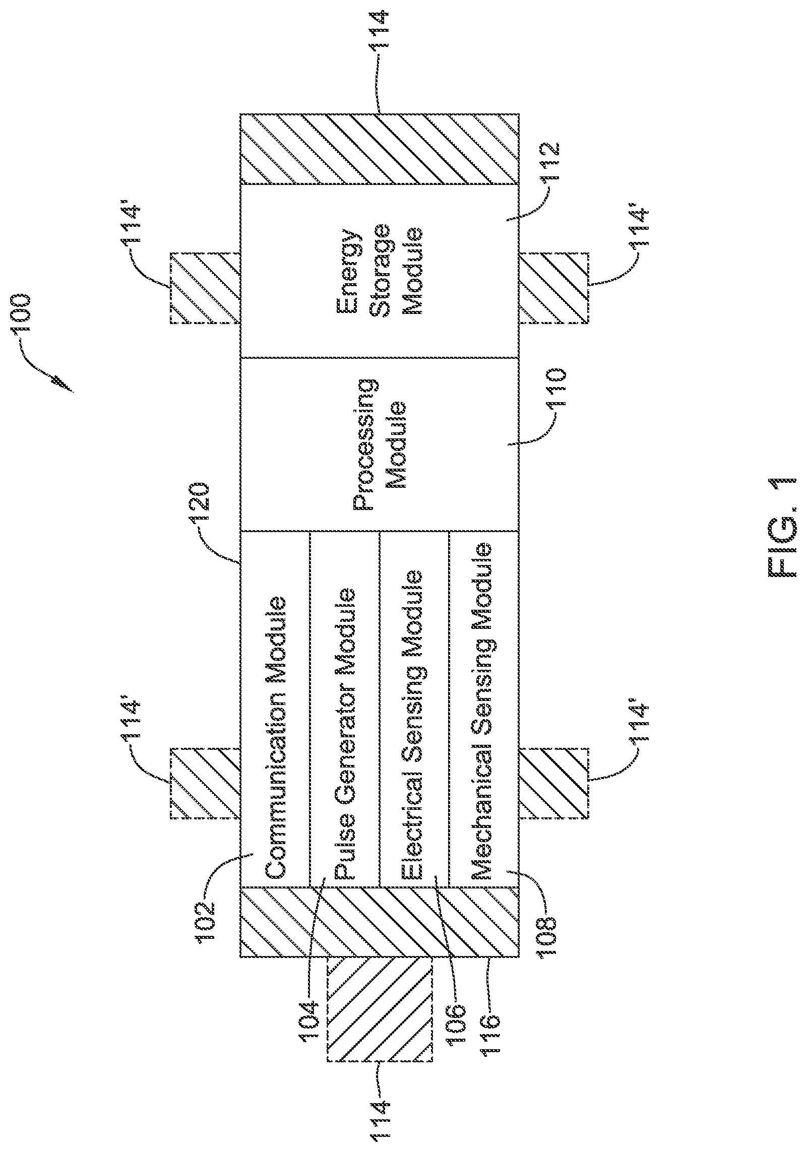
FIG. 1 is a schematic block diagram of an illustrative leadless cardiac pacemaker (LCP) according to one illustrative embodiment of the present disclosure;
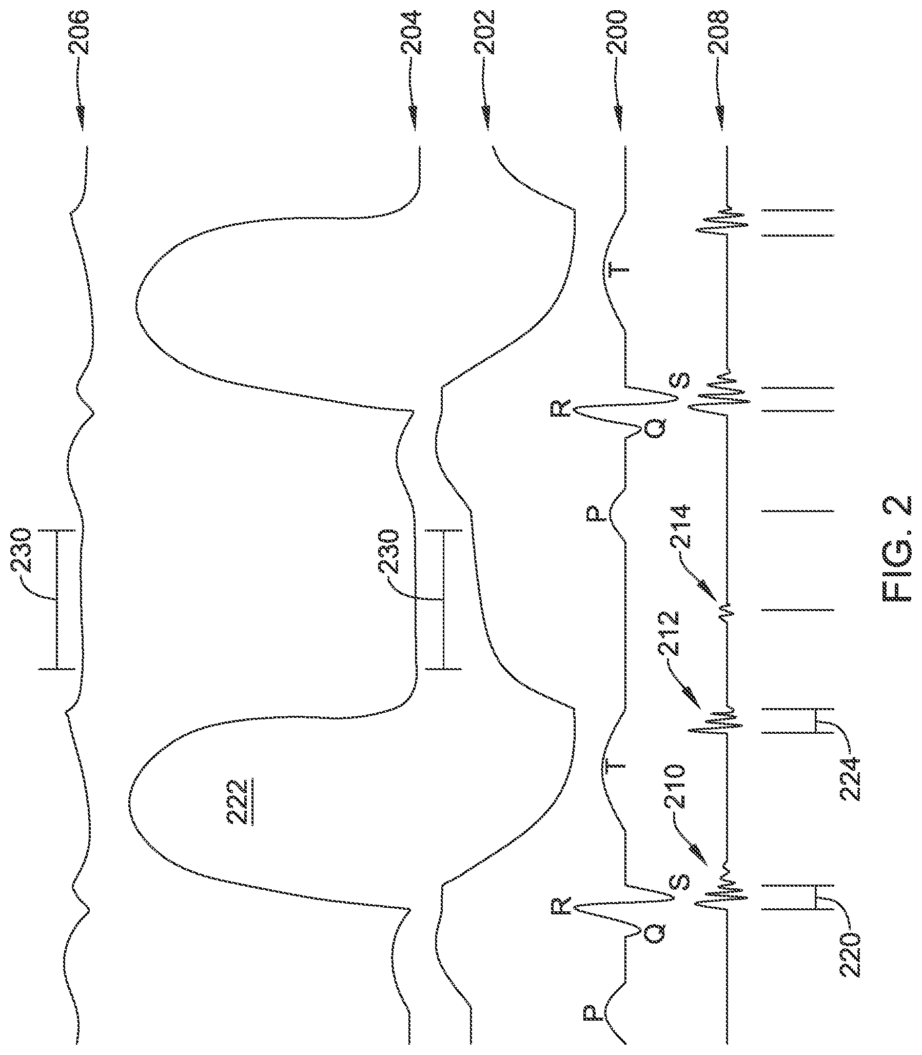
FIG. 2 is a graphic showing cardiac electrical events and intracardiac pressure and volume measurements on a single timeline;
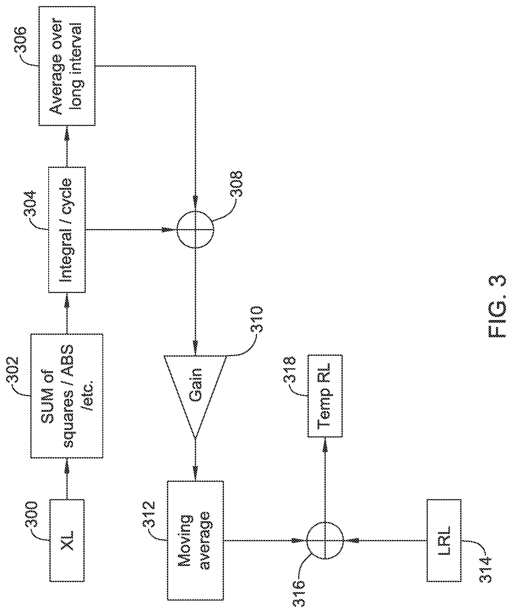
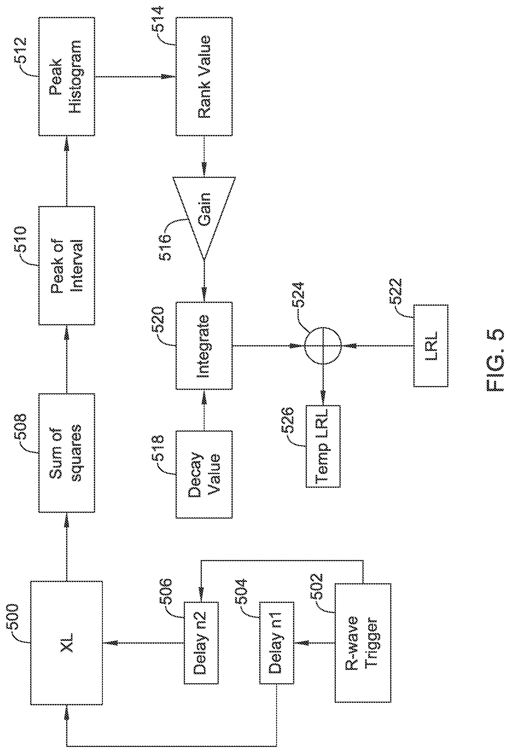
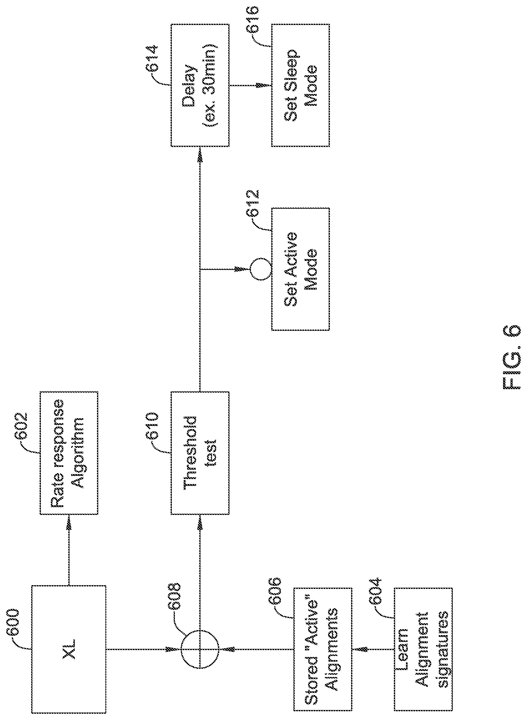
FIGS. 3-6 show several data flow arrangements for illustrative motion sensors;
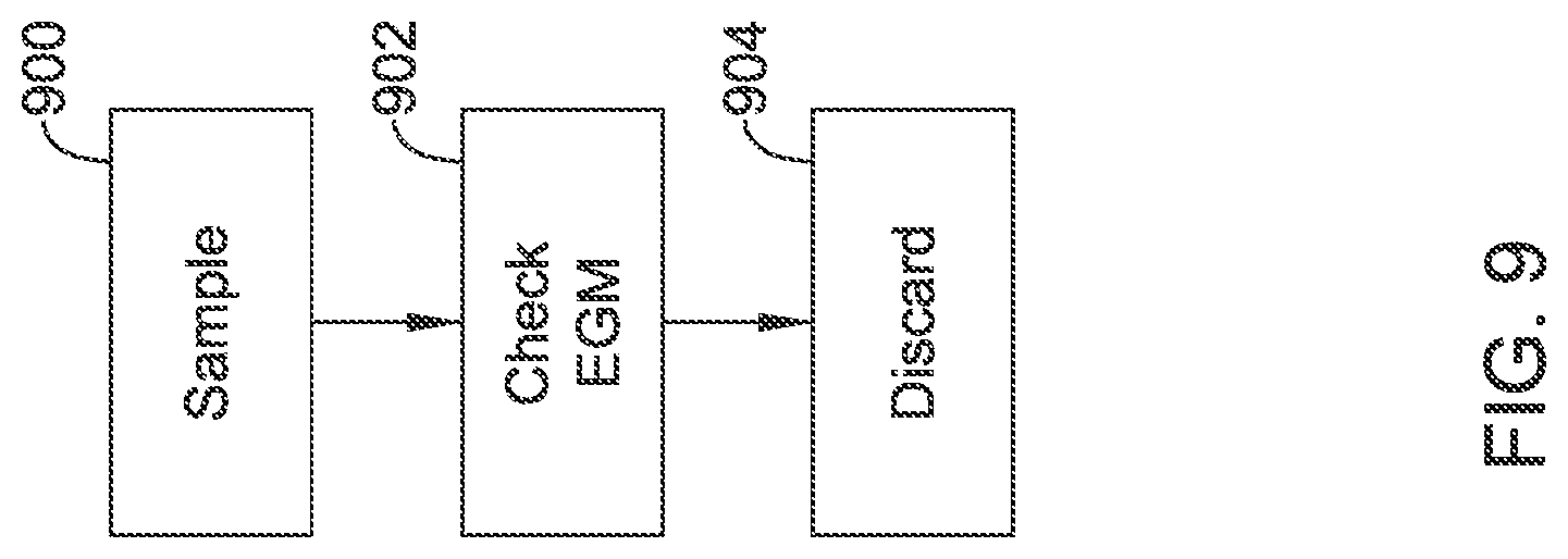
FIGS. 7-11 show several illustrative process flow diagrams; and
FIG. 12 shows a patient having an implantable medical device system in the heart.
DETAILED DESCRIPTION
This disclosure describes systems, devices, and methods for delivering electrical stimulation to a heart in a rate adaptive manner. Healthy people's bodies generally adjust the rate at which their hearts beat in response to higher or lower metabolic needs, for example during exercise or in response to various external stimuli. However, some people develop diseases or conditions which affect their bodies' abilities to cause their hearts to contract in an effective manner. Accordingly, devices in accordance with the present disclosure may be implanted in such people. In some instances, the implanted devices may deliver electrical stimulation on an on-going basis and adjust the rate of delivered electrical stimulation in accordance with sensed physiological parameters indicative of increased metabolic needs.
FIG. 1 is similar to FIG. 1 of commonly assigned U.S. Provisional Patent Application 62/128,340, the disclosure of which is incorporated herein by reference as showing and describing numerous additional details which may be included in the methods, systems and devices discussed herein.
More specifically, FIG. 1 is a conceptual schematic block diagram of an exemplary leadless cardiac pacemaker (LCP) that may be implanted on the heart or within a chamber of the heart and may operate to sense physiological signals and parameters and deliver one or more types of electrical stimulation therapy to the heart of the patient. Example electrical stimulation therapy may include bradycardia pacing, rate responsive pacing therapy, cardiac resynchronization therapy (CRT), anti-tachycardia pacing (ATP) therapy and/or the like. As can be seen in FIG. 1, LCP 100 may be a compact device with all components housed within LCP 100 or directly on housing 120. In some instances, LCP 100 may include communication module 102, pulse generator module 104, electrical sensing module 106, mechanical sensing module 108, processing module 110, energy storage module 112, and electrodes 114. In some examples (not shown), an optional lead or tether may be attached to an implantable device similar to LCP 100 to provide an additional electrode, extended antenna functionality, to couple to a second such implantable device, or to prevent migration.
As depicted in FIG. 1, LCP 100 may include electrodes 114, which can be secured relative to housing 120 and electrically exposed to tissue and/or blood surrounding LCP 100. Electrodes 114 may generally conduct electrical signals to and from LCP 100 and the surrounding tissue and/or blood. Such electrical signals can include communication signals, electrical stimulation pulses, and intrinsic cardiac electrical signals, to name a few. Intrinsic cardiac electrical signals may include electrical signals generated by the heart and may be represented by the cardiac electrogram (EGM), if observed on or in the heart, or the electrocardiogram (ECG), if observed at some distance from the heart.
Electrodes 114 may include one or more biocompatible conductive materials such as various metals or alloys that are known to be safe for implantation within a human body. In some instances, electrodes 114 may be generally disposed on either end of LCP 100 and may be in electrical communication with one or more of modules 102, 104, 106, 108, and 110. In embodiments where electrodes 114 are secured directly to housing 120, an insulating material may electrically isolate the electrodes 114 from adjacent electrodes, housing 120, and/or other parts of LCP 100. In some instances, some or all of electrodes 114 may be spaced from housing 120 and connected to housing 120 and/or other components of LCP 100 through connecting wires. In such instances, the electrodes 114 may be placed on a tail (not shown) that extends out away from the housing 120. As shown in FIG. 1, in some embodiments, LCP 100 may include electrodes 114'. Electrodes 114' may be in addition to electrodes 114, or may replace one or more of electrodes 114. Electrodes 114' may be similar to electrodes 114 except that electrodes 114' are disposed on the sides of LCP 100. In some cases, electrodes 114' may increase the number of electrodes by which LCP 100 may deliver communication signals and/or electrical stimulation pulses, and/or may sense intrinsic cardiac electrical signals, communication signals, and/or electrical stimulation pulses. Electrodes 114 and/or 114' may assume any of a variety of sizes and/or shapes, and may be spaced at any of a variety of spacings. For example, electrodes 114 may have an outer diameter of two to twenty millimeters (mm). In other embodiments, electrodes 114 and/or 114' may have a diameter of two, three, five, seven millimeters (mm), or any other suitable diameter, dimension and/or shape. Example lengths for electrodes 114 and/or 114' may include, for example, one, three, five, ten millimeters (mm), or any other suitable length. As used herein, the length is a dimension of electrodes 114 and/or 114' that extends away from the outer surface of the housing 120. In some instances, at least some of electrodes 114 and/or 114' may be spaced from one another by a distance of twenty, thirty, forty, fifty millimeters (mm), or any other suitable spacing. The electrodes 114 and/or 114' of a single device may have different sizes with respect to each other, and the spacing and/or lengths of the electrodes on the device may or may not be uniform.
In the embodiment shown, communication module 102 may be electrically coupled to electrodes 114 and/or 114' and may be configured to deliver communication pulses to tissues of the patient for communicating with other devices such as sensors, programmers, other medical devices, and/or the like. Communication signals, as used herein, may be any modulated signal that conveys information to another device, either by itself or in conjunction with one or more other modulated signals. In some embodiments, communication signals may be limited to sub-threshold signals that do not result in capture of the heart yet still convey information. The communication signals may be delivered to another device that is located either external or internal to the patient's body. In some instances, the communication may take the form of distinct communication pulses separated by various amounts of time. In some of these cases, the timing between successive pulses may convey information. Communication module 102 may additionally be configured to sense for communication signals delivered by other devices, which may be located external or internal to the patient's body.
Communication module 102 may communicate to help accomplish one or more desired functions. Some example functions include delivering sensed data, using communicated data for determining occurrences of events such as arrhythmias, coordinating delivery of electrical stimulation therapy, and/or other functions. In some cases, LCP 100 may use communication signals to communicate raw information, processed information, messages and/or commands, and/or other data. Raw information may include information such as sensed electrical signals (e.g. a sensed EGM), signals gathered from coupled sensors, and the like. In some embodiments, the processed information may include signals that have been filtered using one or more signal processing techniques. Processed information may also include parameters and/or events that are determined by the LCP 100 and/or another device, such as a determined heart rate, timing of determined heartbeats, timing of other determined events, determinations of threshold crossings, expirations of monitored time periods, activity level parameters, blood-oxygen parameters, blood pressure parameters, heart sound parameters, and the like. Messages and/or commands may include instructions or the like directing another device to take action, notifications of imminent actions of the sending device, requests for reading from the receiving device, requests for writing data to the receiving device, information messages, and/or other messages commands.
In at least some embodiments, communication module 102 (or LCP 100) may further include switching circuitry to selectively connect one or more of electrodes 114 and/or 114' to communication module 102 in order to select which electrodes 114 and/or 114' that communication module 102 delivers communication pulses. It is contemplated that communication module 102 may be communicating with other devices via conducted signals, radio frequency (RF) signals, optical signals, acoustic signals, inductive coupling, and/or any other suitable communication methodology. Where communication module 102 generates electrical communication signals, communication module 102 may include one or more capacitor elements and/or other charge storage devices to aid in generating and delivering communication signals. In the embodiment shown, communication module 102 may use energy stored in energy storage module 112 to generate the communication signals. In at least some examples, communication module 102 may include a switching circuit that is connected to energy storage module 112 and, with the switching circuitry, may connect energy storage module 112 to one or more of electrodes 114/114' to generate the communication signals.
As shown in FIG. 1, a pulse generator module 104 may be electrically connected to one or more of electrodes 114 and/or 114'. Pulse generator module 104 may be configured to generate electrical stimulation pulses and deliver the electrical stimulation pulses to tissues of a patient via one or more of the electrodes 114 and/or 114' to provide electrical stimulation therapies such as bradycardia pacing, ATP, CRT, cardioversion or defibrillation.
The LCP 100 may vary the rate at which pulse generator 104 generates the electrical stimulation pulses, for example in rate adaptive pacing. These are just some examples. When used to treat other ailments, the pulse generator module 104 may generate electrical stimulation pulses suitable for neurostimulation or neuromodulation therapy or the like.
Pulse generator module 104 may include one or more capacitor elements and/or other charge storage devices to aid in generating and delivering appropriate electrical stimulation pulses. In the embodiment shown, pulse generator module 104 may use energy stored in energy storage module 112 to generate the electrical stimulation pulses. In some examples, pulse generator module 104 may include a switching circuit that is connected to energy storage module 112 and may connect energy storage module 112 to one or more of electrodes 114/114' to generate electrical stimulation pulses.
Pulse generator module 104 may include the capability to modify the electrical stimulation pulses, such as by adjusting the pulse width and/or amplitude of the electrical stimulation pulses. When pacing the heart, this may help tailor the electrical stimulation pulses to capture the heart a particular patient, sometimes with reduced battery usage. For neurostimulation therapy, adjusting the pulse width and/or amplitude may help tailor the therapy for a particular application and/or help make the therapy more effective for a particular patient.
In some embodiments, LCP 100 may include an electrical sensing module 106 and mechanical sensing module 108. Electrical sensing module 106 may be configured to sense intrinsic cardiac electrical signals conducted from electrodes 114 and/or 114' to electrical sensing module 106. For example, electrical sensing module 106 may be electrically connected to one or more electrodes 114 and/or 114' and electrical sensing module 106 may be configured to receive cardiac electrical signals conducted through electrodes 114 and/or 114' via a sensor amplifier or the like. In some embodiments, the cardiac electrical signals may represent local information from the chamber in which LCP 100 is implanted. For instance, if LCP 100 is implanted within a ventricle of the heart, cardiac electrical signals sensed by LCP 100 through electrodes 114 and/or 114' may represent ventricular cardiac electrical signals.
Mechanical sensing module 108 may include, or be electrically connected to, various sensors, such as accelerometers, blood pressure sensors, heart sound sensors, piezoelectric sensors, blood-oxygen sensors, and/or other sensors which measure one or more physiological parameters of the heart and/or patient. Mechanical sensing module 108 may gather signals from the sensors indicative of the various physiological parameters. Both electrical sensing module 106 and mechanical sensing module 108 may be connected to processing module 110 and may provide signals representative of the sensed cardiac electrical signals and/or physiological signals to processing module 110. Although described with respect to FIG. 1 as separate sensing modules, in some embodiments, electrical sensing module 106 and mechanical sensing module 108 may be combined into a single module. In at least some examples, LCP 100 may only include one of electrical sensing module 106 and mechanical sensing module 108. In some cases, any combination of the processing module 110, electrical sensing module 106, mechanical sensing module 108, communication module 102, pulse generator module 104 and/or energy storage module may be considered a controller of the LCP 100.
The mechanical sensing module may include, for example, a micro-electro-mechanical system (MEMS) based motion sensor. This may include a 1, 2 or 3 dimensional motion sensor and may take any of numerous forms known in the art. Some examples may include a micro-machine size vibrating element that varies an electrical parameter when motion impacts it. To facilitate sensing, the motion sensor can be turned "on," requiring current drain, and the output can then be sampled to generate an output. Keeping the motion sensor "on" all the time may drain battery sourced current unnecessarily, and so duty cycling is performed to minimize current draw in some embodiments.
Processing module 110 may be configured to direct the operation of LCP 100. For example, processing module 110 may be configured to receive cardiac electrical signals from electrical sensing module 106 and/or physiological signals from mechanical sensing module 108. Based on the received signals, processing module 110 may determine, for example, occurrences and types of arrhythmias. Processing module 110 may further receive information from communication module 102. In some embodiments, processing module 110 may additionally use such received information to determine occurrences and types of arrhythmias. However, in other embodiments, LCP 100 may use the received information instead of the signals received from electrical sensing module 106 and/or mechanical sensing module 108--for instance if the received information is deemed to be more accurate than the signals received from electrical sensing module 106 and/or mechanical sensing module 108 or if electrical sensing module 106 and/or mechanical sensing module 108 have been disabled or omitted from LCP 100.
After determining therapy is needed, processing module 110 may control pulse generator module 104 to generate electrical stimulation pulses in accordance with one or more electrical stimulation therapy regimens. For example, processing module 110 may control pulse generator module 104 to generate pacing pulses with varying parameters and in different sequences to effectuate one or more electrical stimulation therapies. As one example, in controlling pulse generator module 104 to deliver bradycardia pacing therapy, processing module 110 may control pulse generator module 104 to deliver pacing pulses designed to capture the heart of the patient at a regular interval to help prevent the heart of a patient from falling below a predetermined threshold.
In some embodiments, processing module 110 may further control communication module 102 to send information to other devices. For example, processing module 110 may control communication module 102 to generate one or more communication signals for communicating with other devices of a system of devices. For instance, processing module 110 may control communication module 102 to generate communication signals in particular pulse sequences, where the specific sequences convey different information. Communication module 102 may also receive communication signals for potential action by processing module 110.
In some embodiments, processing module 110 may include a pre-programmed chip, such as a very-large-scale integration (VLSI) chip or an application specific integrated circuit (ASIC). In such embodiments, the chip may be pre-programmed with control logic in order to control the operation of LCP 100. By using a pre-programmed chip, processing module 110 may use less power than other programmable circuits while able to maintain basic functionality, thereby potentially increasing the battery life of LCP 100. In other instances, processing module 110 may include a programmable microprocessor or the like. Such a programmable microprocessor may allow a user to adjust the control logic of LCP 100 after manufacture, thereby allowing for greater flexibility of LCP 100 than when using a pre-programmed chip.
Processing module 110, in additional embodiments, may include a memory circuit and processing module 110 may store information on and read information from the memory circuit. In other embodiments, LCP 100 may include a separate memory circuit (not shown) that is in communication with processing module 110, such that processing module 110 may read and write information to and from the separate memory circuit. The memory circuit, whether part of processing module 110 or separate from processing module 110, may be volatile memory, non-volatile memory, or a combination of volatile memory and non-volatile memory.
Collectively the processing module 110, mechanical sensing module 108, electrical sensing module 106, pulse generator module 104, and communication module 102 may be referred to as the operational circuitry of the LCP. In some examples the individual modules 102, 104, 106, 108, 110 may be subcomponents on a single hybrid or circuit board, or even within a single VSLI or ASIC, or may be spread across several hybrids, circuit boards, VSLI or ASIC components. In some examples, certain elements of processing module 110 are performed in the digital domain--such as determining whether to deliver therapy and operating the communication module when awoken for such a purpose--while others are performed in the analog domain--such as ongoing monitoring of the received electrical and/or motion signal until a significant perturbation of either signal or a timeout occurs, allowing the digital circuitry to stay in a low power state by duty cycling to sleep. On whole, the operational circuitry may be configured to perform the various methods shown herein and below claimed, by reference to memory and/or by operation of application-specific circuitry and/or ASIC chips.
Energy storage module 112 may provide a power source to LCP 100 for its operations. In some embodiments, energy storage module 112 may be a non-rechargeable lithium-based battery. In other embodiments, the non-rechargeable battery may be made from other suitable materials. In some embodiments, energy storage module 112 may include a rechargeable battery. For embodiments with a rechargeable battery, there may additionally be a recharging circuit using, for example, a coil that receives an electrical or magnetic field to facilitate recharging transcutaneously, as is well known in the art. In other embodiments, biological energy capture devices may be used to take advantage of energy that can be generated using the cardiac or other biological motion. In still other embodiments, energy storage module 112 may include other types of energy storage devices such as super capacitors.
To implant LCP 100 inside a patient's body, an operator (e.g., a physician, clinician, etc.), may fix LCP 100 to the cardiac tissue of the patient's heart. To facilitate fixation, LCP 100 may include one or more anchors 116. The one or more anchors 116 are shown schematically in FIG. 1. The one or more anchors 116 may include any number of fixation or anchoring mechanisms. For example, one or more anchors 116 may include one or more pins, staples, threads, screws, helix, tines, and/or the like. In some embodiments, although not shown, one or more anchors 116 may include threads on its external surface that may run along at least a partial length of an anchor member. The threads may provide friction between the cardiac tissue and the anchor to help fix the anchor member within the cardiac tissue. In some cases, the one or more anchors 116 may include an anchor member that has a cork-screw shape that can be screwed into the cardiac tissue. In other embodiments, anchor 116 may include other structures such as barbs, spikes, or the like to facilitate engagement with the surrounding cardiac tissue.
In some examples, LCP 100 may be configured to be implanted on a patient's heart or within a chamber of the patient's heart. For instance, LCP 100 may be implanted within any of a left atrium, right atrium, left ventricle, coronary sinus, or right ventricle of a patient's heart. By being implanted within a specific chamber, LCP 100 may be able to sense cardiac electrical signals originating or emanating from the specific chamber that other devices may not be able to sense with such resolution. Where LCP 100 is configured to be implanted on a patient's heart, LCP 100 may be configured to be implanted on or adjacent to one of the chambers of the heart, or on or adjacent to a path along which intrinsically generated cardiac electrical signals generally follow. In these examples, LCP 100 may also have an enhanced ability to sense localized intrinsic cardiac electrical signals and deliver localized electrical stimulation therapy.
In some instances, LCP 100 may be configured to deliver rate-adaptive pacing therapy to a patient's heart. For instance, LCP 100 may be configured to deliver electrical stimulation pulses to the heart of the patient on an on-going basis to help ensure that the patient's heart contracts in a safe and effective manner. LCP 100 may additionally sense one or more signals, for example using electrical sensing module 106 and/or mechanical sensing module 108, and determine, based on the sensed one or more signals, whether to change the rate of delivery of the electrical stimulation pulses.
For example, based on the sensed one or more signals, LCP 100 may determine that there is less of a need for cardiac output, and may decrease the rate of delivery of the electrical stimulation pulses. In other instances, based on the one or more sensed signals, LCP 100 may determine that there is a need for increased cardiac output, and may increase the rate of delivery of the electrical stimulation pulses. Adjusting the rate of delivery of the electrical stimulation pulses based on the sensed one or more signals may extend the battery life of LCP 100 by only requiring higher rates of delivery of electrical stimulation pulses when the sensed one or more signals indicate there is a need for increased cardiac output. Additionally, adjusting the rate of delivery of the electrical stimulation pulses may increase a comfort level of the patient by more closely matching the rate of delivery of electrical stimulation pulses with the cardiac output need of the patient.
Where LCP 100 adjusts the rate of delivery of electrical stimulation pulses based on the sensed one or more signals, LCP 100 may in some cases determine a respiration rate based on the sensed one or more signals. Respiration rate may be indicative of a relative cardiac output need for the patient. For example, an increased respiration rate may indicate that there is a need for increased cardiac output, and a decreased respiration rate may indicate less of a need for cardiac output. Accordingly, and when so provided, LCP 100 may adjust the rate of delivery of the electrical stimulation pulses based on the determined respiration rate.
In at least some examples, LCP 100 may include a motion sensor (such as an accelerometer) and may determine a measure related to the respiration rate based on the sensed motion sensor signal. Where LCP 100 is implanted on a patient's heart or within the heart, the motion sensor signal may include signals indicative of movement related to a number of different causes. For instance, the motion sensor signal may include movement related to the gross movement of the patient, such as walking, bending, or other gross body movements. Additionally, the motion sensor signal may include movement related to the contraction of the heart, particularly when LCP 100 is implanted on or within the heart. Additionally, the motion sensor signal may include movement related to the inhalation and exhalation of the patient (i.e. respiration). For instance, as a patient breathes in and out, the lungs apply different pressure to the heart and the intrathoracic pressure changes accordingly. This change in the intrathoracic pressure may cause changes in the shape and size of the various chambers of the heart, as well as the movement of the heart and the heart chambers. After inhalation, the intrathoracic pressure may be relatively higher, which may decrease the volume of blood that flows into one or more of the chambers of the heart during a cardiac cycle. Conversely, after exhalation, the intrathoracic pressure may be relatively lower, which may allow relatively more blood to enter the chambers of the heart during a cardiac cycle. These differences in the amount of blood flowing into and out of the heart and any movement of the heart or heart chambers due to the changes in intrathoracic pressure may be contained in the motion sensor signal.
A motion sensor may be used to measure inotropic changes in the myocardium; either positive or negative changes. Patients having chronotropic incompetence can still have appropriate contractility responses to increased metabolic demand. For example with increased metabolic demand, contractility increases due to adrenergic excitation. The opposite occurs with decreased metabolic demand.
Although an LCP serves as the platform for much of the below description and above detail, any implantable device having a motion sensor may take advantage of the presently described enhancements. Other devices may include drug or other substance delivery systems, neurostimulator or neuromodulation systems, and implantable cardiac monitoring systems, for example.
FIG. 2 shows several different biological signals in a time-sequenced fashion. For example, the electrocardiograph is shown at 200, including well known P-Q-R-S-T wave sequences as the heart beats. These "waves" represent the electrical signals that flow through the myocardium to trigger muscle contractions during depolarization and subsequent repolarization. At 202, the ventricular volume is represented, with volume peaking at the time of the QRS complex and dropping in response to muscle contraction caused by the QRS complex, with refilling starting as after cardiac repolarization represented by the T-wave.
At 204, the ventricular pressure is represented, with a peak at 222 as the cardiac volume decreases (shown by line 202). Atrial pressure is represented at 206. The atrial pressure 206 illustrates changes that are much smaller than those of the ventricles.
The phonocardiogram is shown at 208, with the first heart sound at 210, over the QRS complex during systole, the second heart sound 212 representing the end of systole and start of diastole, and the third heart sound 214 occurring still later. The first heart sound 210 corresponds to closing of the atrioventricular valves, that is, the tricuspid and mitral valves. The second heart sounds 212 correspond to closure of the aortic and pulmonary valves. The third heart sound 214 is generally less common and of lower amplitude than the first two heart sounds 210, 212 and may relate, it is thought, to blood filling the ventricles. The motion and sounds represented by the changing ventricular volume 202 and heart sounds 210, 212, 214 can all create interference for a motion sensor, which may be sensitive to each of these.
The inventors have recognized that a useful goal in this context is to identify a relatively quiet period of time, illustrated at 230, during which cardiac-sourced interference is reduced. Although the third heart sound 214 may overlap this period 230, it should be noted that the third heart sound 214 is not universally observed and is the lowest amplitude of the heart sounds and so is less likely to cause significant interference. The inventors have recognized that an LCP may be configured for temporal avoidance of cardiac motion interference, enhancing the signal for analysis and potentially avoiding or reducing computational burden associated with other filtering techniques.
FIGS. 3-6 shows several data flow arrangements for illustrative motion sensors. FIG. 3 shows a first example. A sample is taken at 300. The "sample" may represent several discrete data elements. For example, a sample may include data points captured for each of several axes of a multi-axis accelerometer (X, Y, Z, for example) that may serve as a motion sensor; such a sample may be thought of as a vector sample with elements {x[i], y[i], z[i]}. Moreover, a sample may include several close-in-time data points. For example, when "sampling" is performed on a single axis of the output of the accelerometer, 2 or more data points (for example, 2 to 20 data points) may be taken. In one example, four data points may be captured at 400 Hz, yielding a 10 millisecond slice of the output signal as the sample; other rates and quantities may be used. Thus a single sample from a three axis accelerometer could be thought of as a matrix such as:
x[i], x[i+1], x[i+2], x[i+3]
y[i], y[i+1], y[i+2], y[i+3]
z[i], z[i+1], z[i+2], z[i+3]
The math is not so simple as a single number coming out. Computational burdens are presented by such math in an implanted system.
Sampling may be called on a constant basis; historically accelerometer or motion sensor outputs in implantable medical systems would be sampled at rates of 10 to 50 hertz. However, in examples further shown below, sampling occurs in response to detected heart beats identified by analyzing the cardiac electrical signal. For example, the cardiac electrical signal (sometimes referred to as the cardiac electrogram, if captured from within the heart, or electrocardiogram, if captured outside the heart) may be compared to a time-varying threshold to identify the R-wave or QRS complex representative of an individual cardiac cycle. If desired, as alternatives, heart sounds or blood pressure measurements may instead be used to identify a cardiac cycle. As discussed further below, when taking one or more samples with each cardiac cycle, timing of the samples is be selected, in some examples, to avoid certain noise sources.
In the example of FIG. 3, a single axis or multiple axes may be under analysis, with individual samples having several close in time data points. Since there are several data points, the individual data points may be passed on, or may be processed at 302 to take a sum of squares, absolute value sum, mean, or max value, as desired. An integral is taken of the several data points in a given sampling cycle at 304. The integration at 304 may be omitted if a single data point is taken as the sample
The output of the integral 304 is averaged over a long interval at 306 to yield a baseline. At 308, the instantaneous output from block 304 is compared by subtraction to the long interval average from block 306. The difference may be multiplied in a gain stage at 310 and fed into a moving average block 312, to allow smoothing of the motion sensor signal. For example, a patient rolling over in his or her sleep could be detected as significant motion by such a system, but the moving average block 312 would smooth this large motion over a period of in the range of 5 to 30 seconds. Such smoothing would avoid inappropriate rate response to isolated motion.
For simplicity, several examples herein refer a difference being calculated. In some examples, a difference is calculated relative to a baseline by subtraction. In other example, a difference may be a ratio of a measured value to a baseline value, that is, if the baseline is represented by a non-zero measurement output, the difference may be the ratio to the non-zero output. The word difference is intended to cover all such permutations of a comparison to baseline to determine a difference.
The moving average 312 may then be compared at 316 to a rate response level 314 representing the current state of rate response. For example, if the current state is at a base pacing level--that is, no rate response, then the level 314 may be zero, and an increase would be identified if the moving average is greater than level 314. The output 318, which is the temporary response level, is used to modify the existing state.
In some examples, the various blocks shown in FIG. 3 (and further below in FIGS. 4-11) may be implemented as instruction sets stored in non-transitory medium, such as the memory of an implantable medical device, for operation by a microprocessor or microcontroller. In other examples, a state machine architecture may be used with various operations taking place under control of the device as it progresses through a series of analytical states. In some examples, one or more blocks in FIGS. 3-11 may be performed by application specific integrated circuit hardware or other dedicated hardware. For example, processing and integration blocks 304, 306 may be performed by dedicated hardware, while other blocks are performed within a microprocessor.
FIG. 4 shows another example. Here, sampling is performed at block 400 on the basis of a trigger such as an R-wave trigger 402. The R-wave trigger 402 may be more broadly thought of as a trigger based on a predefined electrical cardiac event occurring. For example, a cardiac electrical signal may be monitored using electrodes (such as electrodes 114, 114' of FIG. 1) and compared to a threshold; when the threshold is crossed, a predefined electrical cardiac event is found to have occurred. The threshold may be time-varying and may be adaptive to the sensed cardiac electrical signal amplitude using various known methods in the art. Sampling may occur at first and/or second delays 404, 406 after the trigger event 402 is identified. While several of the below examples focus on identifying a useful delay, it is noted that more than one delay may be selected to take two samples from within one cardiac cycle.
The output sample is may go through computation and filtering 408 (such as amplifying, root-mean-square assessment, smoothing, etc.) and an average signal within the sample may then be calculated at 410. The pre-processing at blocks 408, 410 may be on a per-sample basis, or may be performed for all samples (if multiple are taken) within a cardiac cycle, if desired. The pre-processed sample can be compared to a long term average 412 in block 414, processed further with an optional gain stage 416, and smoothed to generate a moving average at 418. As with FIG. 3, the moving average 418 can then be compared at 422 to the existing activity calculation 420 to yield a change, if needed, to the activity calculation at 424.
In a further example, the trigger 402 may be either a detected cardiac event, if one occurs, or pace delivery if the bradycardia pacing escape threshold is exceeded. In such a design, the first delay 402 may be configured for intrinsic (non-paced) cardiac cycles, and the second delay 404 may be configured for paced cardiac cycles. This accounts for the differences between intrinsic and paced cardiac cycles since, for example, the paced cycles may have different conduction characteristics and wider QRS complexes than intrinsic beats.
FIG. 5 shows another illustrative example. Here, the sample again is taken at 500, based on a trigger 502 and one or more delays 504, 506. In some examples, the delay(s) are selected to identify a "quiet" phase of the cardiac cycle where the heart is not moving significantly. In other examples, the peak activity phase of the heart may be sought to assist in characterizing the physiology thereof for example by identifying certain heart sounds and specifying cardiac motion.
Again, the sample 500 is pre-processed at 508 using, for example, a sum of square approach or the like, and one or more peak motion detection from the interval are identified at 510. For example, it may be desirable to take a comprehensive view of the cardiac motion artifact by sampling at a number of times within a cardiac cycle to then identify peaks and generate a histogram 512. Rank valuation can then be performed at 514, and one or more peaks passed through to the gain and integration stages 516, 520. A decay value may be incorporated as well from block 518 with the decay representing expected value within a cycle. These outputs may be used to compare to the existing state 522 in a comparison at 524 to yield an adjustment calculation 526. In other examples the method may stop with the histogram at 512 which may be useful to monitor, for example, the stages (strength or duration, for example) of cardiac contraction.
FIG. 6 shows another illustrative example. In this example, when a sample is taken at 600 from the motion sensor, the sample can be passed forward to one of the above or below described methods of analyzing the motion sensor output. In addition, the output can be provided to a comparison module at 608. In this "learning" example, a device is provided the opportunity to observe, at relatively high sampling rates (10 to 100 Hz for example) motion sensor output across the entire cardiac cycle for a short period of time--perhaps a few seconds up to a few minutes while a patient is active and/or at rest. Observing such an overall cycle while in multiple states can facilitate the development of an alignment signature 604 indicative of whether the patient is in a specific state. One state of particular interest to reduce energy consumption is the state of rest or sleep.
Alignments for one or more states, including an active state, or, alternatively, a sleep state, can be stored at 606 for use in the comparison at 608. A match threshold is applied at 610 to determine whether there is a match to an active or sleep state. If an active state is identified or cannot be eliminated, then the active motion sensor tracking mode may be set at 612. Otherwise, a passive motion sensor tracking mode is set and kept in place for a delay period, as indicated at 614, and the motion sensor subcomponents of the implantable medical device are put to sleep at 616 until the delay period expires. Illustrative delay periods may range from a minute to an hour. In one example, if the patient appears to be asleep or inactive, a thirty-minute delay is set to conserve energy.
A sleep function as shown in FIG. 6 may be called when the patient's activity level according to the rate response algorithm 602 is at baseline or minimum. In another illustration, a method or device may require the patient's activity level be at baseline for a specified period of time before attempting to determine if the patient is asleep. In another illustration, the delay period may be initially short in a first iteration (for example, 5 minutes) and then extended if the patient appears to remain asleep to longer intervals until a maximum sleep interval is reached. In yet another illustration, if the patient's sensed cardiac rate rises above a preset threshold for a predetermined period, sleep mode 616 may be interrupted.
FIGS. 7-11 show several illustrative process flow diagrams. Starting at block 700, motion sensor data is collected, as well as a second signal data 702, preferably contemporaneously though not necessarily concomitantly. For example, motion sensor data may be captured at a first interval using a first sampling period/repeat rate, while the second sensor data may be captured according to a second timing scheme. In an illustration, motion sensor data 700 may be captured in sets of data points, with each set being a sample, captured at a rate of 50 Hz to 1000 Hz, with sets of 1 to 20 data points, captured in groups at rates of 10 Hz to 50 Hz, while the second sensor data 702 is captured continuously at a rate of 100 to 1000 Hz, with 256 Hz being illustrative. In one embodiment the second signal data is the cardiac electrogram. In another embodiment the second signal data is blood pressure data, which may be captured at a lower rate, but more continuously, than the motion sensor data.
The motion sensor data and second signal data are aligned and correlated at 704, and used to generate a configuration for the motion sensor data 706. For example, the aligning and correlating step may be performed to facilitate identifying a quiet time 720 in the motion sensor data relative to alignment or reference points in the second signal data 702.
To further facilitate the configuration, patient activity 710 and/or the status of pacing therapy 712 can be controlled. For example, the data collection 700, 702 is performed, in one illustration, while the patient is told to remain at rest, thus controlling patient activity 710. In this state, the motion sensor should only identify motion caused by cardiac motion and/or sounds within the heart--since an accelerometer-based motion sensor may be sensitive to vibrations ("sounds") occurring in the heart. Thus a quiet phase of the motion sensor output would provide a good baseline for identifying patient activity. The process may be repeated with pacing on and off, as indicated at 712, to ensure that quiet times 720 can be identified in either circumstance. Moreover, if the quiet time shifts based on whether pacing is on or off, the configuration 706 would be adjusted to ensure the right quiet time is selected for both paced and non-paced beats.
It is envisioned that a system will operate in a learning mode--that is, the system may not necessarily rely on specific landmarks or theoretical bases when selecting a quiet time. However, in reality, it is expected that devices will choose a time period as indicated by FIG. 2 above at 230, a period between the T-wave and the P-wave when the cardiac signal is in a quiescent phase. The configuration 706 that will then be stored would take the form of a value or values indicating an appropriate delay from the QRS complex or R-wave to the expected quiet time.
Alternatively, sampling, with or without delays may be triggered by a different detectable event. For example, the configuration 706 may store a time period from the T-wave or end of the T-wave. The configuration 706 may instead be reflected in identification of a quiescent state of the electrocardiogram where the ECG or EGM is electrically at baseline for a period of time, as such a state would correspond to the period between the T-wave and the P-wave.
For those patients who exhibit a detectable third heart sound, the configuration 706 may be selected to ensure motion sensor sampling before or after the third heart sound in order to avoid it. Such a result may occur from the device learning when a quiet time takes place relative to one or more cardiac signals, or it may be ensured using inputs from a physician.
In some examples a further set of manipulations of the state of the patient may be had. Configuration may be performed while the patient is in a state of rest as well as during patient activity selected to increase the heart rate. In conjunction with the patient activity the output pacing rate may be increased by the implantable device, if needed. For example, a baseline configuration may be used during a learning period and, once data capturing and correlation steps are completed, a tailored configuration can be stored for the patient. By rechecking the configuration at increased heart rates, the appropriate timing of the quiet time at various heart rates can be determined and stored as part of the configuration 706.
In one example, the pacing rate may be increased to confirm the mechanical quiet phase remains quiet at increased rates (or, if the timing of the quiet phase moves, to allow for adjustment). That is, if the quiet time at low rates is no longer quiet at high rates due to motion intrinsic to the heart, the configuration of the quiet time can be adjusted. The quiet time may be preferably selected to avoid inappropriate feedback from the heart itself, which could perpetuate an unnecessarily high cardiac rate if not avoided.
Much of the above presumes a ventricular placement of the implantable device. If an implantable device is placed in the atrium, it may be more suitable to use the P-wave as a trigger point, since it will be the larger signal to the atrial device absent cross-chamber noise. In this instance, the implantable device is more likely to identify a quiet time that may occur during systole, that is, while the ventricles are ejecting blood to the rest of the body.
FIG. 8 shows another example. In this example, the system is shown in more of an operational state. An event is detected at 800. The device will perform sampling of a motion sensor output at 804 in response to the detected event from 800. In some examples, a delay period 802 first must expire prior to the sampling at 804.
Within FIG. 8, the detected event, in some examples, may be the delivery of a pacing output 810, either by the implantable device or by a second implantable device. In another example, the detected event may be the detection of a quiescent state 812 where, for example, the cardiac electrogram remains stable for a period of time (such as 40 milliseconds, about 10 samples at 256 Hz). In another example, the detected event is a predefined event in the electrical cardiac signal such as a P-wave, R-wave, QRS complex or T-wave, as indicated at 814.
The delay 802 may be defined or determined in a number of ways. In some examples, a learning process is used at 820, such as the process of FIG. 7 where the motion sensor output and a second signal are analyzed to look for quiet times in the motion sensor output while the patient is in a controlled state. In another example noted at 822, the delay can be based on a predictive formula; for example, using Bazett's formula or Friderica's formula, the R-T interval can be predicted from a known cardiac beat rate, and the delay can be set to cause sampling after the T-wave is completed. In a still further example, the delay 802 may be adjusted in light of the cardiac rate of the patient, as shown at 824. For example, at higher rates a shorter delay may be needed. Such adjustments in 824 may be made based on learning 820 or prediction 822.
FIG. 9 illustrates a data correction method that may also be used. Following capture of a sample at 900, a device checks a second signal, such as the electrogram, as noted at 902. If a particular event is identified in the second signal, the sample can be discarded, as noted at 904. For example, supposing sampling takes place in response to the R-wave and is intended to occur after the T-wave and before the P-wave, if the check of the second signal electrogram at 902 shows that the T-wave overlaps or P-wave precedes the sample 900, then the quiet phase of the cardiac motion may have been missed. This suggests a sample which may be noisy and may mix or overlap patient motion and cardiac motion. Thus the sample is discarded at 904. Repeated discarding may result in a decision to reconfigure the sampling system, implementation of a higher power approach to sampling (higher duty cycle), or activation of a patient or physician alert function.
Further to the example of FIG. 9, rather than a P-wave or T-wave overlap, the presence of another signal in the electrogram at 902 can trigger discarding the sample. For example, a conducted atrial arrhythmia, or a ventricular extra-systolic beat (such as a premature ventricular contraction) identified within the cardiac electrical signal, or by some other sensor such as heart sounds or a pressure sensor, for example, may be identified at block 902 and used as a basis for discarding a motion sensor signal. The circuitry feature, or software function, which performs such identification may be spurious event identifier.
FIG. 10 shows another illustrative example. Here, motion sensor samples are captured at 1000. A large number of such samples are averaged over time to generate a baseline motion for the patient. If desired, statistical methods may be used to eliminate outlier data prior to setting the baseline by, for example, eliminating samples more than two standard deviations away from a mean. The baselining step 1002 may occur while a patient is ambulatory but more preferably would take place in a controlled setting with the patient generally at rest.
Once a baseline is established at 1002, a sample is taken at 1004. The sample 1004 is then compared to the baseline at 1006, to generate a difference that is used to assess patient activity at 1008. If desired, several samples may be taken and averaged together, or a smoothing function may be applied to a series of samples prior to comparing to the baseline 1006.
FIG. 11 shows a clinical method of establishing a patient configuration. Here, the patient is instructed at 1100 to assume a posture, for example as shown at 1110. Sitting, supine, prone, laying on left or right sign, standing, or other postures may be chosen at 1110. Alternative, the patient is instructed 1100 to engage in a movement, such as walking, jogging, or a favorite exercise, or to hold still or engage in the Valsalva maneuver, as indicated at 1112.
Next, data capture is performed at 1102. Data capture may include capturing data from a motion sensor as well as a second data input or sensor such as the electrogram. Capture of the motion sensor output and second signal may be continuous 1120 or at high rate 1122 for the purposes of configuration, with the intent being that once configuration is completed a lower rate may be implemented.
Steps 1100 and 1102 may be repeated as shown at 1104 with new instructions to the patient for second and subsequent iterations. Once data is captured, the method determines a quiet time in the motion sensor signal using a trigger or reference point identified in the second signal data. The analysis of this type may be performed by the implanted device 1130 or may be performed by an external device in communication with an implanted device 1132.
FIG. 12 shows a patient having an implantable medical device system in the heart. The patient 1200 is shown having a heart 1201 in which a plurality of medical devices are implanted. In this example, a ventricular device is shown at 1204 and an atrial device at 1206. The implantable devices 1204, 1206 may operate independent of one another or may coordinate using conducted communication--or other communication such as RF--therebetween. An external device 1210 such as a programmer is also shown, in this instance with a wand 1212 for placement on the patient to facilitate communication to the implantable devices 1204, 1206.
It is not necessary to have multiple implanted devices, but it is envisioned that at least some patients will have multiple devices. In some examples, one or both implanted device 1204, 1206 has a motion sensor. In some examples, the motion sensor of one of the devices is disabled after configuration has been performed, if it can be determined that performance of one or the other is better or worse and the devices operate in coordination with one another. In some examples, an atrial device 1206 may be of smaller size and lesser mass, and omits a motion sensor which is instead provided in the ventricular device 1204.
Alternatively, the devices may be identical and whichever device has a greater available battery capacity is used for motion capture, while the other device renders a motion sensor inactive. For example, it may be that the atrial device 1206 is anticipated to use less power in therapy delivery than the ventricular device 1204, such that motion sensing is performed with just the atrial device 1206.
In some examples, the two separate devices 1204 and 1206 may provide synchronized motion capture to identify an appropriate configuration. For example, both devices 1204 and 1206 may communicate captured motion data out to the external programmer 1210, where the motion sensing data is captured in overlapping time periods. Motion that is sensed due to patient movement should be identified in both of the devices, while local motion from cardiac chamber movement, for example, would not necessarily show up in each device's motion sensor output. By comparing the signals, the bodily motion signal can be extracted. Next, working backwards, it would be determined which time periods in one or both implanted devise 1204 and 1206 is capturing the bodily motion accurately and without interference from local cardiac motion. A configuration would be identified and stored for one or both implanted devices 1204 and 1206.
A first non-limiting example is an implantable device (ID) comprising a power source, operational circuitry, a motion sensor, and electrodes, the electrodes configured to capture a cardiac electrical signal, wherein the operational circuitry comprises: trigger means for determining that a predefined event has occurred in the heart of the patient using a signal from the electrodes; sampling means for sampling an output of the motion sensor in response to the trigger means. Illustrative examples of a trigger means includes a circuit (such as a comparator) or software implemented instruction for comparing a representation (analog or digital) of a received cardiac signal to a predetermined threshold such as a threshold as described in U.S. Pat. No. 8,565,878, the disclosure of which is incorporated herein by reference. Such triggers are also described above. Illustrative examples of sampling means include any suitable sampling circuit such as a capacitive sample and hold circuit in which, for example, an output is switched to a capacitor, charging the capacitor up or down to a level related to the sampled signal, and a comparator is used to drive a second capacitor to match the sampling capacitor, or a comparator circuit, and an analog-to-digital convertor capable of retaining or passing to memory an output of a measurement, among others. The drawings indicate certain examples including trigger 402 and sampling 400 in FIG. 4, trigger 502 and sampling 500 in FIG. 5, for example.
A second non-limiting example is the ID of the first non-limiting example, wherein the sampling means further comprises delay means for waiting a delay period following activation of the trigger means before sampling the output of the motion sensor. Illustrative delay means may include a timer and associated memory or comparator for setting the duration to run the timer, or may include a capacitor that can be charged to a selected level and then discharged in predictable fashion. Delay is illustrated in the Figures, for example, at FIG. 6, block 614, and FIG. 8, at 802.
A third non-limiting example is an ID as in the second non-limiting example, wherein the motion sensor is configured to operate in a low-power mode except to facilitate the sampling means taking a sample of the output thereof. A fourth non-limiting example is an ID as in either of the second or third non-limiting examples, wherein the predefined event is one of an R-wave, a pacing impulse, or a QRS complex, and the delay period is selected to expire prior to occurrence of a P-wave. A fifth non-limiting example is an ID as in any of the second to fourth non-limiting examples further comprising a spurious event detector configured to determine whether an event occurs during or after the delay period and, if so, the spurious event detector is configured to interrupt the sampling means or cause the sampling means to discard the sampled output of the motion sensor. A sixth non-limiting example is an ID as in the fifth non-limiting example, wherein the specified cardiac event is a ventricular contraction.
A seventh non-limiting example is an ID as in any of the second to sixth non-limiting examples, wherein the operational circuitry includes means for initializing the ID including: collection means to collect a set of data points from the motion sensor and from a cardiac electrical signal from the electrodes contemporaneously; correlating means to correlate time periods within the set of data points from the motion sensor to cardiac activity reflected by the cardiac electrical signal; and setting means to store information indicating when data from the motion sensor is to be captured by reference to specific repeatable elements of the cardiac electrical signal. Illustrative collection means may take the form of a memory location for receiving data for at least temporary storage. The correlating means may take any suitable form for comparing two shapes such as a correlation waveform analysis block or signal processing chip, or a microprocessor or microcontroller with associated memory instructions for comparing two shapes by difference of area, principal components, or wavelet analysis, for example. The setting means may include a volatile or non-volatile memory. An example is in FIG. 6, with collection at blocks 700 and 702, correlation at 704, and setting performed as the configuring step at 706.
An eighth non-limiting example is an ID as in the seventh non-limiting example, wherein the delay means is configured to calculate the delay period from the information stored by the setting means, taking into account a cardiac rate of the patient. A ninth non-limiting example is an ID as in any of the seventh or eight non-limiting examples, wherein: the correlating means is configured to determine when intrinsic mechanical motion of the heart is detected by the motion sensor relative to electrical signals of the heart; and the setting means is configured to store information indicating a time period relative to a specified electrical signal of the heart to avoid capturing intrinsic mechanical motion of the heart with the motion sensor. A tenth non-limiting example is an ID as in any of the seventh to ninth non-limiting examples, wherein the setting means is configured to set a delay to be triggered by detection of a T-wave in the cardiac electrical signal.
An eleventh non-limiting example is an ID as in any of the first to tenth non-limiting examples, wherein the ID includes pacing means to deliver pacing therapy to the patient and the predefined event is delivery of a pacing stimulus by the ID. Illustrative pacing means may include one or more of a voltage supply (such as an amplifier output), a current source (such as a current mirror), or a capacitor (or plurality thereof) or simply a battery output, coupled via the pulse generator module 104 (such as by a multiplexor, switch array or H-Bridge) to one or more of the electrodes 114, 114', for example, and associated instruction sets for operation by the processing module 110.
A twelfth non-limiting example is an implantable device (ID) comprising a power source, operational circuitry, a motion sensor, and electrodes, the electrodes configured to capture a cardiac electrical signal, wherein the operational circuitry comprises: sampling means for sampling a signal from a motion sensor in the ID; baseline calculation means for analyzing the sampled signal over time to generate a baseline output of the motion sensor; present state means for determining a present state indicator from the sampled signal; comparing means to compare the present state indicator to the baseline to yield a difference; activity characterizing means to analyze the difference to determine the patient's activity level. Illustrative sampling means may be as described above. Illustrative baseline calculation means may include analog or digital domain memory or storage locations for capturing an average sampled output of the motion sensor over time, with associated instruction sets for the processing module 110 to use for controlling baseline. For example, block 306 (FIG. 3) takes an average over a long interval to obtain a baseline; block 1002 (FIG. 10) likewise identifies a baseline using captured samples 1000.
Illustrative comparing means may include digital domain software instruction set or module for comparing two digital values, for example, or a comparator, for example, in the analog domain. A difference, as yielded, may be a subtractive difference, a ratio of two numbers/values, or other comparative output. Comparisons of this sort are noted at block 316 (FIG. 3), block 422 (FIG. 4), block 524 (FIG. 5), and block 1006 (FIG. 10).
The activity characterizing means may include a state machine, for example, which operates to change state based on the difference as calculated by the comparing means, for example, assuming baseline to a rest state for the patient, then a difference such as large subtractive difference, or large ratio to the baseline would suggest a high level of activity and be classified in an active state if meeting an active state threshold; and if the difference is a small subtractive difference or ratio, below an inactive state threshold, then the state machine may assume an inactive state. Other such means may be provided, using for example a stored memory location as a characterization of patient activity with plural possible values such as active, inactive, or hysteresis (in-between). Illustratively, the Temporary Response Level (Temp RL, at FIG. 3, block 318; FIG. 4, block 424, and FIG. 5 block 526) may be used as shown in the high level diagram of FIG. 10 to assess activity at block 1008 by the use of binning of the Temp RL to high or low classes, with or without a hysteresis band/bin in the middle. As noted, these may drive state machine logic in some examples.
A thirteenth non-limiting example is an ID as in the twelfth non-limiting example, wherein the baseline calculation means uses a number, M, of individual samples from the motion sensor; the present state means uses a number, N, of individual samples from the motion sensor; and M is an order of magnitude larger than N.
A fourteenth non-limiting example is an ID as in any of the first to tenth, twelfth or thirteen non-limiting examples, wherein the operational circuitry comprises: pacing means to deliver pacing therapy to a patient at a pacing output rate; activity determining means configured to use an output of the motion sensor to calculate an activity level of the patient; and adjusting means to adjust the pacing output rate in view of the activity level. Such activity determining means may be as noted in block 1008 of FIG. 10 and described above. The adjusting means may operate by increasing the pacing rate output when a higher level of patient activity is observed or likely, and reducing the pacing rate output when a lower level of patient activity is observed or likely, both within reasonable boundaries. That is such adjusting would have minimum boundaries (40 to 60 bpm, for example) and upper boundaries (120 to 200 bpm, for example) which may vary depending on patient characteristics and physician decisions.
A fifteenth non-limiting example is an ID as in any of the first to fourteenth non-limiting examples, wherein the ID is configured as a leadless cardiac pacing device for implantation entirely within the heart of the patient without a lead.
A sixteenth non-limiting example is a method of operation in an implantable device comprising: initializing an implantable device (ID) for disposition within the heart of a patient, the ID comprising a motion sensor for detecting movement of the patient, the initializing step being performed by: contemporaneously collecting a set of data points from the motion sensor and from a cardiac electrical signal; correlating time periods within the set of data points from the motion sensor to cardiac activity reflected by the cardiac electrical signal; and configuring the ID to capture data from the motion sensor by reference to specific repeatable elements of the cardiac electrical signal; using the ID as configured in the initializing step to capture cardiac signals of the patient and motion signals for the patient. A seventeenth non-limiting example is a method as in the sixteenth non-limiting example, further comprising; using the motion signals to determine an activity level of the patient; and setting and implementing a pacing rate for the patient using the determined activity level.
An eighteenth non-limiting example is a method as in either of the sixteenth or seventeenth non-limiting examples, wherein the step of configuring the ID to capture data from the motion sensor is performed by: determining when intrinsic mechanical motion of the heart is detected by the motion sensor relative to electrical signals of the heart; and setting a data capture period for the motion sensor relative to a specified electrical signal of the heart to avoid capturing the intrinsic mechanical motion of the heart with the motion sensor.
A nineteenth non-limiting example is a method as in any of the sixteenth to eighteenth non-limiting examples, wherein the step of configuring the ID to capture data from the motion sensor includes determining a delay after a T-wave in the cardiac electrical signal. A twentieth non-limiting example is a method as in the nineteenth non-limiting example, wherein the delay is configured as a function of cardiac rate. A twenty-first non-limiting example is a method as in the twentieth non-limiting example, wherein the cardiac rate is determined as a rate of pacing output of the ID. A twenty-second non-limiting example is a method as in the twentieth non-limiting example, wherein the cardiac rate is determined as an intrinsic rate of the patient's heart.
A twenty-third non-limiting example is a method of operating a motion sensor in an implantable device (ID) for disposition within the heart of a patient, the ID comprising a motion sensor for detecting movement of the patient, the method comprising: the ID determining a predefined event has occurred in the heart of the patient; and the ID waiting a predetermined period of time after the predefined electrical event and sampling an output of the motion sensor.
A twenty-fourth non-limiting example is a method as in the twenty-third non-limiting example, further comprising duty cycling the motion sensor to operate in a window corresponding to the sampling step and otherwise be in a low-power state. A twenty-fifth non-limiting example is a method as in either of the twenty-third or twenty-fourth non-limiting examples, wherein the predefined event is one of an R-wave, a pacing pulse, or a QRS complex, and the predetermined time period is selected to expire prior to occurrence of a P-wave. A twenty-sixth non-limiting example is a method as in any of the twenty-third to twenty-fifth non-limiting examples, further comprising using the output of the motion sensor to determine whether the patient is physically active to facilitate a rate-responsive pacing by the ID. A twenty-seventh non-limiting example is a method as in any of the twenty-third to twenty-sixth non-limiting examples, further comprising using the output of the motion sensor to determine an increase or decrease in cardiac contractility to facilitate a rate-responsive pacing by the ID.
A twenty-eighth non-limiting example is a method as in any of the twenty-third to twenty-seventh non-limiting examples, further comprising determining the predetermined period of time by using an accepted formula for predicting occurrence of a cardiac mechanical or electrical event. A twenty-ninth non-limiting example is a method as in any of the twenty-third to twenty-seventh non-limiting examples further comprising determining the predetermined period of time by initializing the ID by capturing a plurality of outputs from the motion sensor over a period of time including several heart beats to determine a mechanically quiet period in the patient's cardiac cycle relative to the predefined event.
A thirtieth non-limiting example is a method as in any of the twenty-third to twenty-ninth non-limiting examples, wherein the predefined event is one of a P-wave, an R-wave, a QRS complex, a T-wave, or a quiescent period. A thirty-first non-limiting example is a method as in any of the twenty-third to twenty-ninth non-limiting examples wherein the predefined event is delivery of a pacing stimulus. A thirty-second non-limiting example is a method as in any of the twenty-third to thirty-first non-limiting examples, further comprising analyzing a cardiac electrical signal of the patient during at least the predetermined period of time to observe whether a specified cardiac electrical event occurs and, if so, discarding the sampled output of the motion sensor. A thirty-third non-limiting example is a method as in the thirty-second non-limiting example, wherein the specified cardiac event is a ventricular contraction. A thirty-fourth non-limiting example is a method as in the thirty-second non-limiting example, wherein occurrence of the ventricular contraction is determined by identifying a P-wave, R-wave or QRS complex in the electrical cardiac signal at the same time as, or just before, the output of the motion sensor is sampled.
A thirty-fifth non-limiting example is a method of determining whether a patient is active using an implantable device (ID) for disposition within the heart of a patient, the ID comprising a motion sensor for detecting movement of the patient, the method comprising: sampling a signal from a motion sensor in the ID; analyzing the sampled signal over time to generate a baseline; generating a present state indicator from the sampled signal; comparing the present state indicator to the baseline to yield a difference; and comparing the difference to one or more thresholds to characterize the patient's activity level.
A thirty-sixth non-limiting example is a method as in the thirty-fifth non-limiting example, wherein: the present state indicator is generated by averaging a number, M, of individual samples from the motion sensor; the subtractive baseline is generated by averaging a number, N, of individual samples from the motion sensor; and wherein M is an order of magnitude smaller than N. A thirty-seventh non-limiting example is a method as in either of the thirty-fifth or thirty-sixth non-limiting examples, further comprising: providing a pacing output from the ID to the patient's heart, wherein the pacing output has a rate which is adjustable; and adjusting the pacing output rate in light of the patient's activity level.
A thirty-eighth non-limiting example is a method of operating a motion sensor in an implantable device (ID) for disposition within the heart of a patient, the ID comprising a motion sensor for detecting movement of the patient, the method comprising: instructing a patient having the ID implanted in the heart thereof to adopt a set of postures or engage in a movement; capturing a number of motion sensor outputs while the patient is in one or more postures or engaging in one or more movement while capturing a cardiac electrical signal; identifying a quiet period within the cardiac the cardiac electrical signals during which intrinsic motion of the heart does not impact the output of the motion sensor outputs; and configuring the ID to activate and capture data from the motion sensor during the quiet periods. A thirty-ninth non-limiting example is a method as in the thirty-eighth non-limiting example, wherein the quiet time is defined relative to a predetermined event in the cardiac electrogram. A fortieth non-limiting example is a method comprising repeatedly performing the method of the thirty-eighth non-limiting example using one or more of the following: with and without the patient receiving pacing therapy; and for at least first and second postures or activities.
Each of these non-limiting examples can stand on its own, or can be combined in various permutations or combinations with one or more of the other examples. The above detailed description includes references to the accompanying drawings, which form a part of the detailed description. The drawings show, by way of illustration, specific embodiments in which the invention can be practiced. These embodiments are also referred to herein as "examples." Such examples can include elements in addition to those shown or described. However, the present inventors also contemplate examples in which only those elements shown or described are provided. Moreover, the present inventors also contemplate examples using any combination or permutation of those elements shown or described (or one or more aspects thereof), either with respect to a particular example (or one or more aspects thereof), or with respect to other examples (or one or more aspects thereof) shown or described herein.
In the event of inconsistent usages between this document and any documents so incorporated by reference, the usage in this document controls. In this document, the terms "a" or "an" are used, as is common in patent documents, to include one or more than one, independent of any other instances or usages of "at least one" or "one or more." Moreover, in the following claims, the terms "first," "second," and "third," etc. are used merely as labels, and are not intended to impose numerical requirements on their objects.
Method examples described herein can be machine or computer-implemented at least in part. Some examples can include a computer-readable medium or machine-readable medium encoded with instructions operable to configure an electronic device to perform methods as described in the above examples. An implementation of such methods can include code, such as microcode, assembly language code, a higher-level language code, or the like. Such code can include computer readable instructions for performing various methods. The code may form portions of computer program products. Further, in an example, the code can be tangibly stored on one or more volatile, non-transitory, or non-volatile tangible computer-readable media, such as during execution or at other times. Examples of these tangible computer-readable media can include, but are not limited to, hard disks, removable magnetic or optical disks, magnetic cassettes, memory cards or sticks, random access memories (RAMs), read only memories (ROMs), and the like.
The above description is intended to be illustrative, and not restrictive. For example, the above-described examples (or one or more aspects thereof) may be used in combination with each other. Other embodiments can be used, such as by one of ordinary skill in the art upon reviewing the above description.
The Abstract is provided to comply with 37 C.F.R. .sctn. 1.72(b), to allow the reader to quickly ascertain the nature of the technical disclosure. It is submitted with the understanding that it will not be used to interpret or limit the scope or meaning of the claims.
Also, in the above Detailed Description, various features may be grouped together to streamline the disclosure. This should not be interpreted as intending that an unclaimed disclosed feature is essential to any claim. Rather, inventive subject matter may lie in less than all features of a particular disclosed embodiment. Thus, the following claims are hereby incorporated into the Detailed Description as examples or embodiments, with each claim standing on its own as a separate embodiment, and it is contemplated that such embodiments can be combined with each other in various combinations or permutations. The scope of the invention should be determined with reference to the appended claims, along with the full scope of equivalents to which such claims are entitled.
* * * * *
D00000
D00001
D00002
D00003
D00004
D00005
D00006
D00007
D00008
D00009
D00010
D00011
D00012
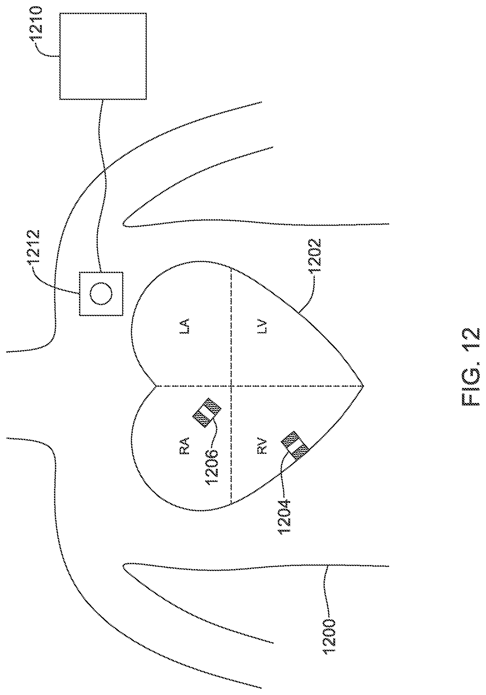
XML
uspto.report is an independent third-party trademark research tool that is not affiliated, endorsed, or sponsored by the United States Patent and Trademark Office (USPTO) or any other governmental organization. The information provided by uspto.report is based on publicly available data at the time of writing and is intended for informational purposes only.
While we strive to provide accurate and up-to-date information, we do not guarantee the accuracy, completeness, reliability, or suitability of the information displayed on this site. The use of this site is at your own risk. Any reliance you place on such information is therefore strictly at your own risk.
All official trademark data, including owner information, should be verified by visiting the official USPTO website at www.uspto.gov. This site is not intended to replace professional legal advice and should not be used as a substitute for consulting with a legal professional who is knowledgeable about trademark law.