Biceps tenodesis delivery tools
Diduch , et al.
U.S. patent number 10,709,488 [Application Number 16/047,650] was granted by the patent office on 2020-07-14 for biceps tenodesis delivery tools. This patent grant is currently assigned to MEDOS INTERNATIONAL S RL. The grantee listed for this patent is Medos International Sarl. Invention is credited to David R. Diduch, Mark H. Getelman, Jacob A. Marks, Gerome Miller, Matthew J. Ravenscroft, Mehmet Z. Sengun, Howard C. Tang.


View All Diagrams
| United States Patent | 10,709,488 |
| Diduch , et al. | July 14, 2020 |
Biceps tenodesis delivery tools
Abstract
Methods and devices are provided for anchoring a ligament or tendon to bone. In particular, various delivery tools, including a variety of sheath inserter tools, are provided. The tools can be used to position a tendon within a prepared bone hole, and to deliver a sheath into the bone hole.
| Inventors: | Diduch; David R. (Charlottesville, VA), Getelman; Mark H. (Tarzana, CA), Marks; Jacob A. (Foxboro, MA), Miller; Gerome (Randolph, MA), Ravenscroft; Matthew J. (Mere, GB), Sengun; Mehmet Z. (Canton, MA), Tang; Howard C. (Boston, MA) | ||||||||||
|---|---|---|---|---|---|---|---|---|---|---|---|
| Applicant: |
|
||||||||||
| Assignee: | MEDOS INTERNATIONAL S RL (Le
Locle, CH) |
||||||||||
| Family ID: | 54360052 | ||||||||||
| Appl. No.: | 16/047,650 | ||||||||||
| Filed: | July 27, 2018 |
Prior Publication Data
| Document Identifier | Publication Date | |
|---|---|---|
| US 20180344376 A1 | Dec 6, 2018 | |
Related U.S. Patent Documents
| Application Number | Filing Date | Patent Number | Issue Date | ||
|---|---|---|---|---|---|
| 14610730 | Jan 30, 2015 | 10076374 | |||
| 62067701 | Oct 23, 2014 | ||||
| Current U.S. Class: | 1/1 |
| Current CPC Class: | A61B 17/88 (20130101); A61F 2/0805 (20130101); A61F 2/0811 (20130101); A61F 2002/0841 (20130101); A61F 2002/0888 (20130101); A61F 2002/0835 (20130101); A61F 2002/0858 (20130101); A61F 2002/0882 (20130101) |
| Current International Class: | A61B 17/88 (20060101) |
| Field of Search: | ;606/104 |
References Cited [Referenced By]
U.S. Patent Documents
| 651949 | June 1900 | Lillie |
| 775427 | November 1904 | Lusted |
| 1426320 | August 1922 | Reid |
| 1925385 | September 1933 | Humes et al. |
| 2243717 | May 1941 | Godoy |
| 2288584 | June 1942 | Longfellow |
| 2381050 | August 1945 | Hardinge |
| 2484655 | October 1949 | Shreve |
| 3073189 | January 1963 | Paige |
| 3089359 | May 1963 | Poulin |
| 3103926 | September 1963 | Cochran et al. |
| 3130763 | April 1964 | Bernard et al. |
| 3298410 | January 1967 | Noboru |
| 4503737 | March 1985 | DiGiovanni |
| 4512344 | April 1985 | Barber |
| 4592346 | June 1986 | Jurgutis |
| 4640271 | February 1987 | Lower |
| 4641640 | February 1987 | Griggs |
| 4687392 | August 1987 | Bidwell |
| 4704055 | November 1987 | Guhring |
| 4711232 | December 1987 | Fischer et al. |
| 4773417 | September 1988 | Moore et al. |
| 4851005 | July 1989 | Hunt et al. |
| 4858810 | August 1989 | Intlekofer et al. |
| 4871289 | October 1989 | Choiniere |
| 4901717 | February 1990 | Moore et al. |
| 4919130 | April 1990 | Stoy et al. |
| 4921383 | May 1990 | Fischer |
| 4950270 | August 1990 | Bowman et al. |
| 4960420 | October 1990 | Goble et al. |
| 4976715 | December 1990 | Bays et al. |
| 4988351 | January 1991 | Paulos et al. |
| 5026376 | June 1991 | Greenberg |
| 5029573 | July 1991 | Chow |
| 5105690 | April 1992 | Lazzara et al. |
| 5116337 | May 1992 | Johnson |
| 5129906 | July 1992 | Ross et al. |
| 5180384 | January 1993 | Mikhail |
| 5209756 | May 1993 | Seedhom et al. |
| 5211647 | May 1993 | Schmieding |
| 5226714 | July 1993 | Wright |
| 5226890 | July 1993 | Ianniruberto et al. |
| 5234435 | August 1993 | Seagrave, Jr. |
| 5236445 | August 1993 | Hayhurst et al. |
| 5242418 | September 1993 | Weinstein |
| 5258012 | November 1993 | Luscombe et al. |
| 5266075 | November 1993 | Clark et al. |
| 5273024 | December 1993 | Menon et al. |
| 5290296 | March 1994 | Phillips |
| 5290297 | March 1994 | Phillips |
| 5314427 | May 1994 | Goble et al. |
| 5320626 | June 1994 | Schmieding |
| 5325868 | July 1994 | Kimmelstiel |
| 5325883 | July 1994 | Orr |
| 5352229 | October 1994 | Goble et al. |
| 5352231 | October 1994 | Brumfield et al. |
| 5380334 | January 1995 | Torrie et al. |
| 5383878 | January 1995 | Roger et al. |
| 5385541 | January 1995 | Kirsch et al. |
| 5409493 | April 1995 | Greenberg |
| 5425490 | June 1995 | Goble et al. |
| 5425733 | June 1995 | Schmieding |
| 5445642 | August 1995 | McNulty et al. |
| 5454811 | October 1995 | Huebner |
| 5456721 | October 1995 | Legrand |
| 5478329 | December 1995 | Ternamian |
| 5505735 | April 1996 | Li |
| 5527341 | June 1996 | Gogolewski et al. |
| 5571104 | November 1996 | Li |
| 5601558 | February 1997 | Torrie et al. |
| 5601562 | February 1997 | Wolf et al. |
| 5607432 | March 1997 | Fucci |
| 5630805 | May 1997 | Ternamian |
| 5632748 | May 1997 | Beck, Jr. et al. |
| 5651790 | July 1997 | Resnick et al. |
| 5653763 | August 1997 | Errico et al. |
| 5655330 | August 1997 | Parsons, III |
| 5658289 | August 1997 | Boucher et al. |
| 5660186 | August 1997 | Bachir |
| 5662655 | September 1997 | Laboureau et al. |
| 5662657 | September 1997 | Carn |
| 5669925 | September 1997 | Saunders |
| 5676499 | October 1997 | Tukala |
| D388171 | December 1997 | Fekete |
| 5700266 | December 1997 | Harryman, II |
| 5702398 | December 1997 | Tarabishy |
| 5713903 | February 1998 | Sander et al. |
| 5720753 | February 1998 | Sander et al. |
| 5738666 | April 1998 | Watson et al. |
| 5746743 | May 1998 | Greenberg |
| 5779707 | July 1998 | Bertholet et al. |
| 5782865 | July 1998 | Grotz |
| RE36020 | December 1998 | Moore et al. |
| 5895351 | April 1999 | Nottage et al. |
| 5897565 | April 1999 | Foster |
| 5899906 | May 1999 | Schenk |
| 5899938 | May 1999 | Sklar et al. |
| 5904685 | May 1999 | Walawalkar |
| 5906632 | May 1999 | Bolton |
| 5941882 | August 1999 | Jammet |
| 5948000 | September 1999 | Larsen et al. |
| 5948001 | September 1999 | Larsen |
| 5957953 | September 1999 | DiPoto et al. |
| 5961520 | October 1999 | Beck, Jr. et al. |
| 5961521 | October 1999 | Roger |
| 5968078 | October 1999 | Grotz |
| 5993458 | November 1999 | Vaitekunas et al. |
| 6024758 | February 2000 | Thal |
| 6027523 | February 2000 | Schmieding |
| 6077267 | June 2000 | Huene |
| 6117139 | September 2000 | Shino |
| 6123711 | September 2000 | Winters |
| 6143016 | November 2000 | Bleam et al. |
| 6143017 | November 2000 | Thal |
| 6221107 | April 2001 | Steiner et al. |
| 6231606 | May 2001 | Graf et al. |
| 6251119 | June 2001 | Addis |
| 6270518 | August 2001 | Pedlick et al. |
| D448482 | September 2001 | Bellofatto et al. |
| 6283948 | September 2001 | McKernan et al. |
| 6306138 | October 2001 | Clark et al. |
| 6319270 | November 2001 | Grafton et al. |
| 6325805 | December 2001 | Ogilvie et al. |
| 6379361 | April 2002 | Beck, Jr. et al. |
| 6405863 | June 2002 | Dhindsa |
| 6443956 | September 2002 | Ray |
| 6464706 | October 2002 | Winters |
| 6517519 | February 2003 | Rosen et al. |
| 6517564 | February 2003 | Grafton et al. |
| 6533816 | March 2003 | Sklar |
| 6544281 | April 2003 | ElAttrache et al. |
| 6554862 | April 2003 | Hays et al. |
| 6558389 | May 2003 | Clark et al. |
| 6562044 | May 2003 | Cooper |
| 6579295 | June 2003 | Supinski |
| 6592587 | July 2003 | Roger |
| 6599290 | July 2003 | Bailey et al. |
| 6613065 | September 2003 | Lajtai |
| 6632245 | October 2003 | Kim |
| 6663605 | December 2003 | Chan |
| 6673115 | January 2004 | Resch et al. |
| 6702817 | March 2004 | Beger et al. |
| 6712822 | March 2004 | Re et al. |
| 6755815 | June 2004 | Schultz |
| 6755836 | June 2004 | Lewis |
| 6780188 | August 2004 | Clark et al. |
| 6827722 | December 2004 | Schoenefeld |
| 6871740 | March 2005 | Cao |
| 6875214 | April 2005 | Supinski |
| 6875216 | April 2005 | Wolf |
| 6887271 | May 2005 | Justin et al. |
| 6939379 | September 2005 | Sklar |
| 6942664 | September 2005 | Voor et al. |
| 6955678 | October 2005 | Gabriel et al. |
| 7074203 | July 2006 | Johanson |
| 7083647 | August 2006 | Sklar et al. |
| 7104999 | September 2006 | Overaker |
| 7204839 | April 2007 | Dreyfuss et al. |
| 7235060 | June 2007 | Kraus |
| 7261716 | August 2007 | Strobel et al. |
| 7309346 | December 2007 | Martinek |
| 7309355 | December 2007 | Donnelly et al. |
| 7329272 | February 2008 | Burkhart |
| 7341591 | March 2008 | Grinberg |
| 7341592 | March 2008 | Walters et al. |
| 7413542 | August 2008 | Kucklick et al. |
| 7442202 | October 2008 | Dreyfuss |
| 7468074 | December 2008 | Caborn et al. |
| 7476228 | January 2009 | Abdou |
| 7481830 | January 2009 | Wall et al. |
| 7556638 | July 2009 | Morgan et al. |
| 7572283 | August 2009 | Meridew |
| 7588575 | September 2009 | Colleran et al. |
| 7611521 | November 2009 | Lubbers et al. |
| 7651528 | January 2010 | Montgomery et al. |
| 7697861 | April 2010 | Shindo et al. |
| D615572 | May 2010 | Harpaz |
| 7713300 | May 2010 | Meridew et al. |
| 7736364 | June 2010 | Stone |
| 7766920 | August 2010 | Ciccone |
| 7828090 | November 2010 | Drivdahl et al. |
| 7833244 | November 2010 | Cerundolo |
| 7837731 | November 2010 | Sklar |
| 7883510 | February 2011 | Kim et al. |
| 7909826 | March 2011 | Serhan et al. |
| 7918288 | April 2011 | Drivdahl et al. |
| 7922730 | April 2011 | Raines, Jr. |
| 7959650 | June 2011 | Kaiser et al. |
| 7963952 | June 2011 | Wright, Jr. et al. |
| 7963983 | June 2011 | Cerundolo |
| 7967861 | June 2011 | Montgomery et al. |
| 7993369 | August 2011 | Dreyfuss |
| 8012083 | September 2011 | Kucklick et al. |
| 8021403 | September 2011 | Wall et al. |
| 8034083 | October 2011 | Abdelgany et al. |
| 8043308 | October 2011 | Bittenson |
| 8048158 | November 2011 | Hays et al. |
| 8051929 | November 2011 | Drivdahl et al. |
| 8057524 | November 2011 | Meridew |
| 8075575 | December 2011 | Gonzalez-Hernandez |
| 8100916 | January 2012 | Kumar |
| 8123749 | February 2012 | Serhan et al. |
| 8128658 | March 2012 | Kaiser et al. |
| 8187309 | May 2012 | Castaneda et al. |
| 8202295 | June 2012 | Kaplan |
| 8206446 | June 2012 | Montgomery |
| 8216131 | July 2012 | Kucklick |
| 8221455 | July 2012 | Shurnas et al. |
| 8221498 | July 2012 | Boucher et al. |
| 8226714 | July 2012 | Beck, Jr. et al. |
| 8231654 | July 2012 | Kaiser et al. |
| 8241298 | August 2012 | Sengun et al. |
| 8273086 | September 2012 | Serhan et al. |
| 8277464 | October 2012 | Bittenson |
| 8282651 | October 2012 | Ciccone et al. |
| 8292555 | October 2012 | Shaffer |
| 8328716 | December 2012 | Schmieding et al. |
| 8343195 | January 2013 | Rathbun et al. |
| 8348972 | January 2013 | Soltz et al. |
| 8361152 | January 2013 | McCormack et al. |
| 8377089 | February 2013 | Lipchitz et al. |
| 8430909 | April 2013 | Dreyfuss |
| 8435293 | May 2013 | Donnelly et al. |
| 8435294 | May 2013 | Montgomery et al. |
| 8465545 | June 2013 | Montgomery et al. |
| 8506573 | August 2013 | Dreyfuss et al. |
| 8512376 | August 2013 | Thornes |
| 8512405 | August 2013 | Baird |
| 8523902 | September 2013 | Heaven et al. |
| 8523903 | September 2013 | Kilburn-Peterson et al. |
| 8529610 | September 2013 | Graf et al. |
| 8535377 | September 2013 | Myers et al. |
| 8545535 | October 2013 | Hirotsuka et al. |
| 8562680 | October 2013 | Hays et al. |
| 8608765 | December 2013 | Jurbala |
| 8617197 | December 2013 | Friedman et al. |
| 8617219 | December 2013 | Oren et al. |
| 8636799 | January 2014 | Sklar et al. |
| 8647385 | February 2014 | Boucher et al. |
| 8663279 | March 2014 | Burkhart et al. |
| 8663325 | March 2014 | Graf |
| 8672960 | March 2014 | Briganti et al. |
| 8672967 | March 2014 | DiMatteo et al. |
| 8672968 | March 2014 | Stone et al. |
| 8721650 | May 2014 | Fanton et al. |
| 8747470 | June 2014 | Beck, Jr. et al. |
| 8758227 | June 2014 | Kucklick et al. |
| 8771223 | July 2014 | Patton et al. |
| 8771303 | July 2014 | Jurbala |
| 8778023 | July 2014 | Sklar |
| 8784431 | July 2014 | Harder et al. |
| 8790368 | July 2014 | Sullivan et al. |
| 8821383 | September 2014 | Mirza |
| 8821527 | September 2014 | Farnan et al. |
| 8821557 | September 2014 | Corradi |
| 8840665 | September 2014 | Young et al. |
| 8845725 | September 2014 | Barwood et al. |
| 8870877 | October 2014 | Koogle, Jr. |
| 8932354 | January 2015 | Barwood et al. |
| 8939983 | January 2015 | Stone et al. |
| 8956410 | February 2015 | Donnelly et al. |
| 9056010 | June 2015 | Shea et al. |
| 9060748 | June 2015 | Housman et al. |
| 9060772 | June 2015 | Gonzalez-Hernandez |
| 9095331 | August 2015 | Hernandez et al. |
| 9241783 | January 2016 | Trenhaile |
| 9277911 | March 2016 | Hernandez |
| 9289283 | March 2016 | Baird |
| 9301751 | April 2016 | Sullivan et al. |
| 9314240 | April 2016 | Paulk |
| 9693856 | July 2017 | Sengun |
| 9795412 | October 2017 | Sinha |
| 9833229 | December 2017 | Hernandez et al. |
| 10231823 | March 2019 | Piccirillo et al. |
| 10231824 | March 2019 | Piccirillo et al. |
| 2001/0021855 | September 2001 | Levinson |
| 2002/0077631 | June 2002 | Lubbers et al. |
| 2002/0151977 | October 2002 | Paes et al. |
| 2002/0164218 | November 2002 | Aguirre |
| 2002/0188301 | December 2002 | Dallara et al. |
| 2003/0125749 | July 2003 | Yuan et al. |
| 2003/0153921 | August 2003 | Stewart et al. |
| 2003/0153926 | August 2003 | Schmieding et al. |
| 2003/0225456 | December 2003 | Ek |
| 2003/0233095 | December 2003 | Urbanski et al. |
| 2004/0068262 | April 2004 | Lemos |
| 2004/0073219 | April 2004 | Skiba et al. |
| 2004/0073222 | April 2004 | Koseki |
| 2004/0176767 | September 2004 | Bickley |
| 2004/0193217 | September 2004 | Lubbers |
| 2004/0230194 | November 2004 | Urbanski et al. |
| 2004/0267361 | December 2004 | Donnelly et al. |
| 2005/0075668 | April 2005 | Lizardi |
| 2005/0251137 | November 2005 | Ball |
| 2006/0004378 | January 2006 | Raines et al. |
| 2006/0015110 | January 2006 | Pepper |
| 2006/0116685 | June 2006 | Urbanski et al. |
| 2007/0005068 | January 2007 | Sklar |
| 2007/0156153 | July 2007 | Jiang et al. |
| 2007/0162124 | July 2007 | Whittaker |
| 2007/0255172 | November 2007 | Pflueger |
| 2007/0288031 | December 2007 | Dreyfuss et al. |
| 2008/0027430 | January 2008 | Montgomery et al. |
| 2008/0109038 | May 2008 | Steiner et al. |
| 2008/0161864 | July 2008 | Beck et al. |
| 2008/0215060 | September 2008 | Garcia et al. |
| 2008/0228186 | September 2008 | Gall et al. |
| 2008/0228224 | September 2008 | Sauer et al. |
| 2008/0275431 | November 2008 | Stone et al. |
| 2008/0275469 | November 2008 | Fanton et al. |
| 2009/0112270 | April 2009 | Lunn et al. |
| 2009/0138043 | May 2009 | Kohm |
| 2009/0171400 | July 2009 | van der Burg et al. |
| 2009/0192608 | July 2009 | Paulos |
| 2009/0275994 | November 2009 | Phan |
| 2009/0281581 | November 2009 | Berg |
| 2009/0287259 | November 2009 | Trenhaile et al. |
| 2009/0312763 | December 2009 | McCormack et al. |
| 2009/0312782 | December 2009 | Park |
| 2009/0318923 | December 2009 | Burkhart et al. |
| 2010/0016869 | January 2010 | Paulk et al. |
| 2010/0069958 | March 2010 | Sullivan et al. |
| 2010/0106194 | April 2010 | Bonutti |
| 2010/0121348 | May 2010 | van der Burg |
| 2010/0130989 | May 2010 | Bourque et al. |
| 2010/0145395 | June 2010 | Graf et al. |
| 2010/0174369 | July 2010 | Wang et al. |
| 2010/0198271 | August 2010 | Leone |
| 2010/0217393 | August 2010 | Theofilos |
| 2010/0241124 | September 2010 | Housman |
| 2010/0249801 | September 2010 | Sengun et al. |
| 2011/0004247 | January 2011 | Lechmann |
| 2011/0009885 | January 2011 | Graf et al. |
| 2011/0015675 | January 2011 | Howard et al. |
| 2011/0071579 | March 2011 | Reach, Jr. |
| 2011/0098727 | April 2011 | Kaiser et al. |
| 2011/0106013 | May 2011 | Whittaker et al. |
| 2011/0106252 | May 2011 | Barwood |
| 2011/0106253 | May 2011 | Barwood |
| 2011/0112550 | May 2011 | Heaven et al. |
| 2011/0112558 | May 2011 | Whayne et al. |
| 2011/0251621 | October 2011 | Sluss et al. |
| 2011/0257691 | October 2011 | Sutterlin |
| 2011/0270323 | November 2011 | Olsen |
| 2012/0010668 | January 2012 | Shimko |
| 2012/0057949 | March 2012 | Canizares, Jr. |
| 2012/0059379 | March 2012 | Homan et al. |
| 2012/0109156 | May 2012 | Overes et al. |
| 2012/0109299 | May 2012 | Li et al. |
| 2012/0116459 | May 2012 | Nottmeier |
| 2012/0130374 | May 2012 | Bouduban et al. |
| 2012/0136357 | May 2012 | Torrie et al. |
| 2012/0150190 | June 2012 | Rabiner et al. |
| 2012/0150301 | June 2012 | Gamache et al. |
| 2012/0211543 | August 2012 | Euteneuer |
| 2012/0215232 | August 2012 | Olsen |
| 2012/0245686 | September 2012 | Park |
| 2012/0316565 | December 2012 | Stark |
| 2013/0006302 | January 2013 | Paulk |
| 2013/0103054 | April 2013 | Housman |
| 2013/0103080 | April 2013 | Hernandez |
| 2013/0125714 | May 2013 | Dahners |
| 2013/0158597 | June 2013 | Hernandez |
| 2013/0158664 | June 2013 | Palmatier et al. |
| 2013/0190817 | July 2013 | Bouduban |
| 2013/0197534 | August 2013 | Lauderbaugh et al. |
| 2013/0197591 | August 2013 | Corradi |
| 2013/0238036 | September 2013 | Sinha |
| 2013/0267998 | October 2013 | Vijay et al. |
| 2013/0268010 | October 2013 | Santangelo |
| 2013/0310842 | November 2013 | Winkler et al. |
| 2013/0325128 | December 2013 | Perloff et al. |
| 2013/0331942 | December 2013 | Baird |
| 2013/0338710 | December 2013 | Heaven et al. |
| 2014/0005686 | January 2014 | Patton et al. |
| 2014/0046369 | February 2014 | Heaven et al. |
| 2014/0081324 | March 2014 | Sengun |
| 2014/0107713 | April 2014 | Pech et al. |
| 2014/0171983 | June 2014 | Graf et al. |
| 2014/0172095 | June 2014 | Graf et al. |
| 2014/0188166 | July 2014 | Cobb et al. |
| 2014/0228898 | August 2014 | Gordon |
| 2014/0236183 | August 2014 | Graf et al. |
| 2014/0243978 | August 2014 | Beck, Jr. et al. |
| 2014/0243982 | August 2014 | Miller |
| 2014/0249579 | September 2014 | Heaven et al. |
| 2014/0257384 | September 2014 | Dreyfuss et al. |
| 2014/0277133 | September 2014 | Foerster |
| 2014/0277134 | September 2014 | ElAttrache et al. |
| 2014/0309668 | October 2014 | Sullivan et al. |
| 2014/0343604 | November 2014 | Frank |
| 2014/0364862 | December 2014 | Bennett et al. |
| 2015/0018878 | January 2015 | Rizk et al. |
| 2015/0018947 | January 2015 | Barwood |
| 2015/0039030 | February 2015 | Saliman et al. |
| 2015/0066042 | March 2015 | Cummins et al. |
| 2015/0173741 | June 2015 | Housman |
| 2015/0190130 | July 2015 | Groh |
| 2015/0238327 | August 2015 | Cheng et al. |
| 2016/0113643 | April 2016 | Diduch et al. |
| 2016/0113644 | April 2016 | Diduch |
| 2016/0113756 | April 2016 | Diduch |
| 2016/0113757 | April 2016 | Diduch |
| 2016/0113758 | April 2016 | Diduch |
| 2016/0310260 | October 2016 | Sengun et al. |
| 2017/0265988 | September 2017 | Sengun et al. |
| 2017/0290655 | October 2017 | Piccirillo et al. |
| 2017/0290656 | October 2017 | Piccirillo et al. |
| 2018/0296319 | October 2018 | Diduch et al. |
| 2018/0344376 | December 2018 | Diduch |
| 2019/0029805 | January 2019 | Piccirillo et al. |
| 2019/0029806 | January 2019 | Piccirillo et al. |
| 2020/0008928 | January 2020 | Diduch et al. |
| 2020/0129171 | April 2020 | Diduch et al. |
| 2013201310 | May 2015 | AU | |||
| 1378439 | Nov 2002 | CN | |||
| 101394795 | Mar 2009 | CN | |||
| 102098969 | Jun 2011 | CN | |||
| 102292032 | Dec 2011 | CN | |||
| 102438548 | May 2012 | CN | |||
| 102470007 | May 2012 | CN | |||
| 202515702 | Nov 2012 | CN | |||
| 102905629 | Jan 2013 | CN | |||
| 103209647 | Jul 2013 | CN | |||
| 103445850 | Dec 2013 | CN | |||
| 203789970 | Aug 2014 | CN | |||
| 10325139 | Dec 2004 | DE | |||
| 1110510 | Jun 2001 | EP | |||
| 1 491 162 | Dec 2004 | EP | |||
| 2 327 374 | Jun 2011 | EP | |||
| 2918238 | Sep 2015 | EP | |||
| 3020371 | May 2016 | EP | |||
| 2918238 | Nov 2017 | EP | |||
| 200513740 | Jan 2005 | JP | |||
| 2005-66135 | Mar 2005 | JP | |||
| 2005-506864 | Mar 2005 | JP | |||
| 2005-323700 | Nov 2005 | JP | |||
| 2007-50269 | Mar 2007 | JP | |||
| 2007-306979 | Nov 2007 | JP | |||
| 200886769 | Apr 2008 | JP | |||
| 2011516795 | May 2011 | JP | |||
| 2011-528270 | Nov 2011 | JP | |||
| 2014-171673 | Sep 2014 | JP | |||
| WO-9428799 | Dec 1994 | WO | |||
| 97/31517 | Aug 1997 | WO | |||
| WO-0130253 | May 2001 | WO | |||
| WO-2007110863 | Oct 2007 | WO | |||
| 2009/055800 | Apr 2009 | WO | |||
| 2012129206 | Sep 2012 | WO | |||
| WO-2012125905 | Sep 2012 | WO | |||
| WO-2012129617 | Oct 2012 | WO | |||
| WO-2012138777 | Oct 2012 | WO | |||
| WO-2014150053 | Sep 2014 | WO | |||
Other References
|
European Search Report for EP Application No. 15191001.5, dated Apr. 1, 2016. (7 pages). cited by applicant . European Search Report for EP Application No. 15191002.3, dated Apr. 15, 2016. (8 pages). cited by applicant . European Search Report for EP Application No. 15191010.6, dated Apr. 4, 2016. (6 pages). cited by applicant . European Search Report for EP Application No. 15191011.4, dated Apr. 1, 2016. (6 pages). cited by applicant . European Search Report for EP Application No. 15191013.0, dated Apr. 14, 2016. (7 pages). cited by applicant . European Search Report for EP Application No. 16166686.2, dated Sep. 20, 2016. (8 pages). cited by applicant . European Search Report for EP Application No. 17165700.0, dated Aug. 11, 2017. (12 pages). cited by applicant . European Search Report for EP Application No. 17165749.7, dated Aug. 21, 2017. cited by applicant . Chinese Search Report issued in related CN Application No. 201510696822.2 (5 pages). cited by applicant . Translation of International Search Report for CN Application No. 201510697570.5 dated Mar. 1, 2019 (3 pages). cited by applicant . Translation of Chinese Search Report for CN Application No. 201510696510.1 dated May 26, 2019 (4 pages). cited by applicant . Chinese Search Report for CN Application No. 201510696528.1 dated Jun. 25, 2019 (16 pages). cited by applicant. |
Primary Examiner: Gibson; Eric S
Parent Case Text
CROSS-REFERENCE TO RELATED APPLICATIONS
The present application is a divisional of U.S. patent application Ser. No. 14/610,730 filed Jan. 30, 2015, entitled "BICEPS TENODESIS DELIVERY TOOLS," which claims priority to U.S. Provisional Appl. No. 62/067,701 filed on Oct. 23, 2014 and entitled "Biceps Tenodesis Implants and Delivery Devices," which are hereby incorporated by reference in their entireties.
Claims
What is claimed is:
1. A tendon anchoring system, comprising: an outer shaft having an inner lumen extending therethrough and a sheath alignment protrusion formed on a distal end thereof; an inner shaft disposed within the outer shaft and having first and second prongs formed on a distal end thereof, the prongs being movable between an extended position in which the prongs extend distally beyond the distal end of the outer shaft, and a retracted position in which the prongs are retracted into the distal end of the outer shaft, the prongs extending along opposed sides of the sheath alignment protrusion on the outer shaft; a handle assembly coupled to a proximal end of each of the first and second shafts.
2. The tendon anchoring system of claim 1, wherein the sheath alignment protrusion has a generally conical shape.
3. The tendon anchoring system of claim 2, wherein the sheath alignment protrusion includes first and second opposed cut-outs formed therein and configured to receive the first and second prongs of the inner shaft.
4. The tendon anchoring system of claim 1, wherein the distal end of the outer shaft is closed with an elongate slot formed therein for receiving the first and second prongs therethrough.
5. A method for anchoring a tendon to bone, comprising: manipulating an inserter tool to insert a sheath coupled to a distal end of the inserter tool through tissue, the sheath having a guidewire mated thereto and extending through the inserter tool; positioning a tendon between a pair of prongs on a distal end of the inserter tool, and manipulating the inserter tool to advance the sheath, with the tendon between the prongs, into a bone hole, wherein a locking mechanism on a handle assembly of the inserter tool maintains the guidewire and the prongs in a locked position relative to one another; moving the locking mechanism on the handle assembly to an unlocked position and manipulating the handle assembly to retract the prongs relative to the guidewire; and removing the inserter tool such that the sheath with the guidewire mated thereto remains in the bone hole.
6. The method of claim 5, wherein the inserter tool includes first and second shafts, and wherein the prongs are formed on the first shaft, and manipulating the handle assembly to retract the prongs relative to the guidewire comprises moving the first shaft relative to the second shaft.
7. The method of claim 6, wherein the locking mechanism extends between a handle on the first shaft and a handle on the second shaft to block movement of the first and second shafts relative to one another when the locking mechanism is in a locked position.
8. The method of claim 6, wherein the first shaft includes an actuator coupled to a proximal end thereof, and wherein the locking mechanism prevents movement of the actuator when in a locked position, and the locking mechanism releases the actuator when it is moved to the unlocked position.
Description
FIELD
Surgical devices and methods are provided for anchoring tissue to bone, and more particularly surgical implants, delivery tools, and methods are provided for securing a biceps tendon to the humerus.
BACKGROUND
Disorders of the long head of the biceps tendon are a common source of shoulder pain and may occur in association with other diagnoses such as rotator cuff tears, superior labrum anterior posterior tears, impingement syndrome and capsular injuries, or may be present as an isolated source of shoulder pain. The treatment options for disorders of the long head of the biceps (LHB) continue to evolve and can include LHB tenodesis. In a tenodesis procedure, a suture is passed through the base of the LHB to locate the LHB in the subacromial space and to provide proximal control during the dissection. Once the suture is placed, the LHB is cut near the glenoid attachment. A sizer can be used to measure the tendon size and to thereby determine the appropriately sized bone screw. Once the screw is selected, a bone hole is drilled and a tendon fork is then used to push the tendon down into the bone hole. A bone screw is then delivered into the bone hole to anchor the tendon within the bone hole.
While current procedures can provide an effective means for anchoring a tendon to bone, they can suffer from several drawbacks. For example, current procedures require the use of numerous tools, which can lead to a prolonged procedure and increased costs. The use of a screw can also increase the risk of damage to the tendon, as rotation of the screw into the bone hole can tear through the tendon. Moreover, it can be difficult to maintain the desired tension on the tendon while the screw is being implanted, as the tendon can slip during insertion of the screw. Any tension applied to the tendon during insertion of the anchor can also cause the anchor to back-out of the bone hole.
Accordingly, there remains a need for improved methods and devices for anchoring tissue to bone, and in particular for performing a biceps tenodesis.
SUMMARY
Various implants, tools and methods are provided for attaching a biceps tendon to a bone.
In one embodiment, an anchor inserter tool is provided including a first elongate body having first and second prongs extending distally from a distal end thereof and configured to extend along opposed slots formed in a sheath of an anchor assembly. The anchor inserter tool can additionally include a second elongate body slidably disposed relative to the first elongate body, and a handle assembly coupled to a proximal end of the first and second elongate bodies. The handle assembly can include a locking mechanism that is movable between a locked position, in which the locking mechanism prevents movement of the first and second elongate bodies relative to one another, and an unlocked position in which the first and second elongate bodies are axially slidable relative to one another.
In various embodiments, the first elongate body of the anchor inserter tool can be an inner shaft and the second elongate body can be an outer shaft disposed around the inner shaft. In other embodiments, the second elongate body of the anchor inserter tool can be an inner shaft and the first elongate body can be an outer shaft disposed around the inner shaft. In other aspects, the first elongate body can include a lumen configured to receive a proximal end of a guidewire coupled to a sheath of an anchor assembly. The handle assembly can include a guidewire lock configured to selectively engage and prevent movement of a guidewire disposed within the handle.
In other embodiments, the handle assembly can include an actuator coupled to the first elongate body and configured to move the first elongate body axially with respect to the second elongate body. The actuator can be rotatable relative to the handle assembly such that rotation of the actuator is effective to cause axial translation of the inner and outer shafts relative to one another. In other aspects, the actuator can be pivotable relative to the handle assembly such that pivotal movement of the actuator is effective to cause axial translation of the inner and outer shafts relative to one another.
Some embodiments can include an actuator with at least one handle extending in a perpendicular direction from the first elongate body. In other embodiments the actuator can extend proximally from the proximal end of the first elongate body. The actuator can include at least one finger loop.
In another embodiment, the handle assembly can have a pistol-grip configuration with a stationary housing and a pivotable trigger. The first elongate body can be an inner shaft and the second elongate body can be an outer shaft disposed around the inner shaft, and the handle assembly can include an actuator configured to move the inner shaft proximally with respect to the outer shaft to retract the first and second prongs of the inner shaft into the outer shaft.
In another embodiment, a tendon anchoring system is provided with an outer shaft having an inner lumen extending therethrough and a sheath alignment protrusion formed on a distal end thereof. The tendon anchoring system also includes an inner shaft disposed within the outer shaft and having first and second prongs formed on a distal end thereof, the prongs being movable between an extended position in which the prongs extend distally beyond the distal end of the outer shaft, and a retracted position in which the prongs are retracted into the distal end of the outer shaft. The prongs can extend along opposed sides of the sheath alignment protrusion on the outer shaft. The tendon anchoring system can further be provided with a handle assembly coupled to a proximal end of each of the first and second shafts.
In one embodiment, the sheath alignment feature can have a generally conical shape. In other aspects, the sheath alignment feature can include first and second opposed cut-outs formed therein and configured to receive the first and second prongs of the inner shaft. In another embodiment, the distal end of the outer shaft can be closed with an elongate slot formed therein for receiving the first and second prongs therethrough.
In other embodiments, a method for anchoring a tendon to bone is provided and includes manipulating an inserter tool to insert a sheath coupled to a distal end of the inserter tool through tissue, the sheath having a guidewire mated thereto and extending through the inserter tool. The method can additionally include positioning a tendon between a pair of prongs on a distal end of the inserter tool, and manipulating the inserter tool to advance the sheath, with the tendon between the prongs, into a bone hole. A locking mechanism on a handle assembly of the inserter tool can maintain the guidewire and the prongs in a locked position relative to one another. The method further can include moving the locking mechanism on the handle assembly to an unlocked position and manipulating the handle assembly to retract the prongs relative to the guidewire, and removing the inserter tool such that the sheath with the guidewire mated thereto remains in the bone hole.
The inserter tool can include first and second shafts. The prongs can be formed on the first shaft, and manipulating the handle assembly to retract the prongs relative to the guidewire can include moving the first shaft relative to the second shaft.
In various embodiments, the locking mechanism can extend between a handle on the first shaft and a handle on the second shaft to block movement of the first and second shafts relative to one another when the locking mechanism is in a locked position.
In another embodiment, the first shaft can include an actuator coupled to a proximal end thereof, and the locking mechanism can prevent movement of the actuator when in a locked position, and the locking mechanism can release the actuator when it is moved to the unlocked position. The locking mechanism can also extend through a handle of the inserter tool to block movement of the first and second shafts relative to one another when the locking mechanism is in a locked position. The locking mechanism can further include two separate elements, each operatable independently from one another to block movement of the first and second shafts relative to one another and separately to block movement of the guidewire.
BRIEF DESCRIPTION OF THE DRAWINGS
The invention will be more fully understood from the following detailed description taken in conjunction with the accompanying drawings, throughout which arrows can be used to represent possible motion, in which:
FIG. 1A is a side view of a sheath inserter tool and a sheath, showing a lock in a locked position;
FIG. 1B is another side view of the sheath inserter tool of FIG. 1A showing a lock in an unlocked position;
FIG. 1C is another side view of the sheath inserter tool of FIG. 1B with an actuator moved proximally;
FIG. 2A is a side view of another embodiment of a sheath inserter tool, showing a sheath coupled to the device and being implanted in bone;
FIG. 2B a side view of the sheath inserter tool of FIG. 2A, showing an outer shaft retracted from the sheath;
FIG. 3A is a side view of another embodiment of a sheath inserter tool;
FIG. 3B is a side view of the sheath inserter tool of FIG. 3A, showing a sheath coupled to the device and being implanted in bone;
FIG. 3C is a side view of the sheath inserter tool of FIG. 3B, showing an outer shaft retracted from the sheath;
FIG. 4A is a side view of another embodiment of a sheath inserter tool, showing a sheath coupled to the device and being implanted in a bone hole;
FIG. 4B is a side view of the sheath inserter tool of FIG. 4A, showing an inner shaft of the device retracted from the sheath;
FIG. 5A is a side view of another embodiment of a sheath inserter tool, showing a sheath coupled to the device and being implanted in a bone hole, with circles representing figure positions;
FIG. 5B is a side view of the sheath inserter tool of FIG. 5A, showing an inner shaft of the device retracted from the sheath;
FIG. 6A is a perspective view of another embodiment of a sheath inserter tool;
FIG. 6B is side perspective view of a shaft locking mechanism of the tool of FIG. 6A;
FIG. 6C is a perspective view of the shaft locking mechanism of FIG. 6B shown disposed on the inner shaft of the sheath inserter tool of FIG. 6A;
FIG. 6D is a perspective view of portions of the sheath inserter tool of FIG. 6A showing features for hindering movement of the inner shaft relative to the outer shaft;
FIG. 6E is a perspective view of a guidewire locking mechanism of the sheath inserter tool of FIG. 6A;
FIG. 6F is a perspective view of the guidewire locking mechanism of FIG. 6E shown mounted on the sheath inserter tool of FIG. 6A;
FIG. 6G is a perspective view of the guidewire locking mechanism of FIG. 6E shown engaging a guidewire of the sheath inserter tool of FIG. 6A;
FIG. 7 is a side view of another embodiment of a sheath inserter tool;
FIG. 8 is a side view of yet another embodiment of a sheath inserter tool;
FIG. 9 is a side view of another embodiment of a handle portion of a sheath inserter tool;
FIG. 10A is a side view of another embodiment of a sheath inserter tool having a rotating actuator;
FIG. 10B is an enlarged side view of a handle portion of the sheath inserter tool of FIG. 10A;
FIG. 11A is a side view of a handle portion of yet another embodiment of a sheath inserter tool;
FIG. 11B is a side view of the sheath inserter tool of FIG. 11A, showing a sheath mating thereto and being implanted in bone;
FIG. 11C is a side view of the sheath inserter tool of FIG. 11B, showing an inner shaft retracted from the sheath;
FIG. 12 is a side and perspective view of one embodiment of a sheath alignment feature;
FIG. 13 is a side view and perspective of another embodiment of a sheath alignment feature;
FIG. 14 is a side and perspective view of another embodiment of a sheath alignment feature;
FIG. 15 is a side perspective view of a distal end of one embodiment of a cannula;
FIG. 16 is a side view of the cannula of FIG. 15, showing a forked inserter extending distally therefrom;
FIG. 17 is a side view of the cannula and forked inserter of FIG. 16 about to anchor a tendon against a bone surface;
FIG. 18 is a side perspective view of another embodiment of a distal portion of a cannula having threads formed thereon;
FIG. 19 is a side perspective view of another embodiment of a cannula having ribs formed thereon;
FIG. 20 is side view of the cannula of FIG. 19;
FIG. 21 is a side perspective view a distal portion of another embodiment of a inserter tool and anchor;
FIG. 22 is a side perspective view of the inserter tool and anchor of FIG. 21 coupled together;
FIG. 23 is a side view of one embodiment of a sheath protector;
FIG. 24 is a perspective view of another embodiment of a sheath protector;
FIG. 25 is a side view of the sheath protector of FIG. 25, shown about to be passed through tissue;
FIG. 26 is a side view of another embodiment of a sheath protector;
FIG. 27 is a side view of an embodiment of a sheath protector;
FIG. 28 is a side view of additional embodiments of a sheath protector;
FIG. 29 is a perspective view of the sheath protector of FIG. 28 loaded onto a distal end of a sheath and sheath inserter tool;
FIG. 30 is another perspective view of the sheath, inserter tool, and sheath protector of FIG. 29 with forks on the sheath inserter tool being passed through the protector; and
FIG. 31 is another perspective view of the assembly of FIG. 30 showing the sheath protector retracted further relative to the sheath.
DETAILED DESCRIPTION
Certain exemplary embodiments will now be described to provide an overall understanding of the principles of the structure, function, manufacture, and use of the devices and methods disclosed herein. One or more examples of these embodiments are illustrated in the accompanying drawings. Those skilled in the art will understand that the devices and methods specifically described herein and illustrated in the accompanying drawings are non-limiting exemplary embodiments and that the scope of the present invention is defined solely by the claims. The features illustrated or described in connection with one exemplary embodiment may be combined with the features of other embodiments. Such modifications and variations are intended to be included within the scope of the present invention.
Reference throughout the specification to "various embodiments," "some embodiments," "one embodiment," or "an embodiment", or the like, means that a particular feature, structure, or characteristic described in connection with the embodiment is included in at least one embodiment. Thus, appearances of the phrases "in various embodiments," "in some embodiments," "in one embodiment," or "in an embodiment", or the like, in places throughout the specification are not necessarily all referring to the same embodiment. Furthermore, the particular features, structures, or characteristics may be combined in any suitable manner in one or more embodiments. Thus, the particular features, structures, or characteristics illustrated or described in connection with one embodiment may be combined, in whole or in part, with the features structures, or characteristics of one or more other embodiments without limitation.
It will be appreciated that the terms "proximal" and "distal" may be used throughout the specification with reference to a clinician manipulating one end of an instrument used to treat a patient. The term "proximal" refers to the portion of the instrument closest to the clinician and the term "distal" refers to the portion located furthest from the clinician. It will be further appreciated that for conciseness and clarity, spatial terms such as "vertical," "horizontal," "up," and "down" may be used herein with respect to the illustrated embodiments. However, surgical instruments may be used in many orientations and positions, and these terms are not intended to be limiting and absolute.
In general, methods and devices are provided for anchoring a ligament or tendon to bone. In an exemplary embodiment, the methods and devices are used to perform a biceps tenodesis, however a person skilled in the art will appreciate that the devices and methods can be used in various procedures and for anchoring any tissue to bone. In particular, various delivery tools for implanting a sheath of an anchor assembly within a bone hole are provided. The tools can be used to position a tendon within a prepared bone hole, and to deliver a sheath, and optionally a guidewire coupled to the sheath, into the bone hole. Once the sheath is implanted within a bone hole, a sheath expander can be inserted into the sheath, e.g., using a driver tool. The sheath expander will cause the sheath to expand, thereby anchoring the sheath, with the tendon positioned therearound, within the bone hole.
A person skilled in the art will appreciate that the delivery tools and methods disclosed herein can be used with a variety of implants and other surgical devices, including measuring devices, drills, and mallets, etc. In some embodiments, the system can include any one or more of the following components: an anchor assembly or an implant having a sheath and expander that is received within the sheath; a sheath inserter tool; a driver tool; and a loader. The components of the system can reduce the number of steps required to perform a biceps tenodesis, and can do so with minimal risk of injuring to the tendon. In an exemplary embodiment, the tools are configured for use with the anchors and drivers disclosed in U.S. patent application Ser. No. 14/610,618 entitled "Biceps Tenodesis Implants and Delivery Tools," and U.S. patent application Ser. No. 14/610,626 entitled "Biceps Tenodesis Anchor Implants," each of which is filed on even date herewith and incorporated by reference herein in its entirety.
The apparatus and methods described herein may have a number of advantages over existing techniques for preforming bicep tenodesis. In particular, the entire attachment preparation procedure can be straightforward and requires a surgeon to take only a few quick steps to affix the implant structure including the sheath and the expander to the bone. A risk of damaging the tendon during rotation of the expander or any other technique requiring rotation of a component in direct contact with the tendon may be avoided. As a result, a risk of causing trauma to the tendon can be reduced and the time required to prepare and affix the tendon can be significantly reduced, which can facilitate the surgery and mitigate inconvenience to the patient. In addition, the described techniques can help save operating room costs.
As indicated above, various inserter tools are provided for inserting a sheath into a bone hole. The inserter tools can also be used to perform various other functions in connection with insertion of the sheath into a bone hole. For example, the inserter tools can be effective to initially measure a size of a tendon. Multiple inserter tools having different sizes can be provided, with the sizes corresponding to the appropriately sized sheath to be used therewith. The inserter tools can also be configured to insert or "plunge" a tendon into a pre-drilled bone hole, and to maintain the tendon within the bone hole while delivering a sheath into the bone hole. The inserter tools can further be configured to receive a guidewire therein that is coupled to the sheath. This can allow the sheath with the guidewire mated thereto to be delivered into a bone hole, and the guidewire can thereafter remain with the sheath and facilitate delivery of the an expander into the sheath. In certain exemplary embodiments, the inserter tool can be configured to fixedly engage the guidewire to prevent movement thereof during plunging of the tendon and during delivery of the sheath, and it can be configured to selectively release the guidewire once the sheath is implanted to allow the tool to be removed from the guidewire, leaving the sheath implanted with the guidewire extending therefrom.
FIGS. 1A-1C illustrate one exemplary embodiment of a sheath inserter tool shown having a sheath coupled thereto. As shown, the sheath inserter tool 300 generally includes a handle assembly 302 having a proximal end 300p with a proximal knob 303 and a distal end 300d with a distal actuator 304. The actuator 304 is coupled to a proximal end of an outer shaft 306 that extends distally from the actuator 304. The knob 303 is coupled to a proximal end of an inner shaft 310 that is slidably coupled to and extends proximally from the actuator 304. While not shown, the inner shaft 310 can include a distal end that mates to the actuator 304 such that the actuator 304 and outer shaft 306 are slidably movable relative to the inner shaft 310, but that prevents disengagement of the inner shaft 310 from the actuator 304 and outer shaft 306. By way of non-limiting example, the mating feature can be in the form of a flange formed on a distal end of the inner shaft 310 and sized larger than an opening formed in a proximal end of the actuator 304 to prevent passage of the flange therethrough. The outer shaft 306 can also include features at a distal end thereof for interacting with a sheath, as will be discussed below. Moreover, the sheath inserter tool 300 can include a locking mechanism for controlling movement of the inner and outer shafts 310, 306 relative to one another, as will be discussed in more detail below.
The actuator 304 can have a variety of configurations, but in the illustrated embodiment, the actuator 304 on the outer component has a general T-shape configuration to facilitate grasping thereof. The actuator 304 can have a blind bore extending therein from the distal end 300d and terminating just distal to the proximal-most end. The blind bore can be configured to receive a proximal end of the outer shaft 306 for mating the shaft to the actuator 304. In an exemplary embodiment, the proximal end of the outer shaft 306 is fixedly and non-movably mated to the actuator 304, e.g., using adhesive, welding, a threaded engagement, or any other mating mechanism known in the art.
The actuator 304 can also include various features to facilitate grasping and actuation thereof. As shown, the actuator 304 extends laterally outward with respect to the shaft 306 and includes distal facing finger-gripping surfaces 340a, 340b. The proximal end 300p of the handle assembly 302 can be placed in a user's palm and the user's fingers can be positioned within the finger-gripping surfaces 340a, 340b to allow the user to pull the actuator 304 proximally with respect to the inner shaft 310 and knob 303. Since the actuator 304 is fixedly and non-movably mated to the outer shaft 306, movement of the actuator 304 relative to the knob 303 moves the outer shaft 306 relative to the inner shaft 310.
The knob 303 of the handle assembly 302 can also have a variety of configurations. In the illustrated embodiment, the knob 303 is generally cylindrical and is fixedly mated to a proximal end of the inner shaft 310. Various mating techniques, such as those described above, can be used to mate the two components.
As indicated above, the outer shaft 306 is coupled to and extends from the actuator 304 and can have a generally elongate cylindrical shape with a fork 308 on a distal end 300d thereof. The fork 308 can function to both measure a tendon, and to facilitate insertion of the tendon and sheath 100 into a bone hole. As shown, the fork 308 includes first and second elongate prongs 324a, 324b that are configured to extend longitudinally along opposed sides of the sheath 100 when the sheath is coupled to the distal end of the outer shaft 306. The elongate prongs 324a, 324b can each have various shapes, such as a square or rectangular cross-sectional shape. The fork prongs 324a, 324b preferably have a maximum width Wp that is sized to fit within a bone tunnel sized to receive the sheath. The outer shaft 306 can also have an outer diameter D.sub.b that matches the maximum width Wp of the prongs, or in other embodiments the outer diameter D.sub.b of the outer shaft 306 can be greater than the maximum width Wp of the prongs to allow the distal end of the outer shaft 306 to act as a hard stop to limit an insertion depth of the prongs into a bone hole. The pair of prongs 324a, 324b can extend distally beyond the distal end of the outer shaft 306 by a predetermined distance D to thereby define a u-shaped recess 322 between the pair of prongs 324a, 324b. The u-shaped recess 322 can be configured to receive the sheath 100 therein, with the prongs 324a, 324b extending along the opposed sidewall cut-outs in the sheath 100.
As indicated above, the handle can include additional features for controlling movement of the inner and outer shafts 310, 306 relative to one another. As shown in FIGS. 1A-1C, the handle assembly 302 includes a lock 314 disposed between the knob 303 and the actuator 304. The lock can be mounted on the inner shaft 310 and it can be configured to rotate about its fixed point at the proximal end of the inner shaft 310. When in a locked position as shown in FIG. 1A, the lock 314 extends along the entire length of the inner shaft 310 and extends between the knob 303 and the actuator 304, thereby preventing proximal movement of the actuator 304 and thus preventing the inner and outer shafts 310, 306 from moving longitudinally with respect to each other. In order to move the actuator 304 and the outer shaft 306 proximally relative to the inner shaft 310, the lock 314 can be rotated 90 degrees to a perpendicular position, as shown in FIG. 1B. Since the lock 314 is no longer blocking movement of the actuator 304, the actuator 304 can be moved proximal from the position shown in FIG. 1B to the position shown in FIG. 1C.
This movement of the actuator 304 and outer shaft 310 coupled thereto is effective to retract the prongs on the distal end of the outer shaft 310 with respect to the sheath 100. In particular, as shown in FIG. 1C, the sheath can include a guidewire 140 mated thereto. The guidewire 140 can extend from the sheath 100, proximally through the outer shaft 306, and through the inner shaft 310. The knob 303 can include an internal feature for engaging the guidewire, such as threads formed therein for threadably mating to threads formed on a proximal end of the guidewire, or a compressible material that engages the guidewire by press-fit or any other technique known in the art. With the guidewire being mated to the knob 303, the knob 303 will maintain the guidewire, and the sheath mated thereto, in a fixed position during proximal movement of the actuator 304 and outer shaft 306 relative to the knob 303 and inner shaft 310. A person skilled in the art will appreciate that the guidewire does not need to be engaged within the knob, and in other embodiments the guidewire could be slid into the cannulation in the knob without being held by any engagement feature.
In use, the lock 314 is preferably in the longitudinal position, as seen in FIG. 1A, during insertion of the tool and sheath through tissue, such that the lock 314 effectively blocks the actuator 304 and prevents any movement of the inner and outer shafts 310, 306 relative to one another. In this configuration, the sheath 100 is loaded onto the distal end of the inserter and the fork 308 is in a fully extended position, extending distally beyond the sheath 100. As seen in FIG. 1B, upon rotation of the lock 314 to the unlocked position, the actuator 304 may be moved proximally. Proximal movement of the actuator 304 will move the outer shaft 306 proximally, as shown in FIG. 1C. The fork 308, attached to the outer shaft 306, is thus moved proximally and withdrawn from the sheath 100. The tool 300 can be removed leaving the sheath 100, with the guidewire attached thereto, implanted in the bone hole. As described in the aforementioned applications, incorporated herein by reference, a driver tool can then be used to insert an expander, such as a screw, into the sheath to thereby anchor the sheath and a tendon positioned therearound, within the bone hole. In an exemplary embodiment, the expander is delivered over the guidewire and into the sheath.
A person skilled in the art will appreciate that the various features shown with respect to FIGS. 1A-1C can be used in combination with any of the other devices disclosed herein, and that the features of the other devices disclosed herein can similarly be used with respect to FIGS. 1A-1C. By way of non-limiting example, each of the tools disclosed herein can include a guidewire grasper that is configured to engage and releasably retain a guidewire in a fixed position with respect to the inner or outer components of the tool, i.e., the component that does not have the fork. Moreover, each of the tools disclosed herein can additionally or alternatively include a locking mechanism that is configured to lock the inner and outer components relative to one another, and the locking mechanism can have any of the various configurations disclosed herein. The tools can also include other features, such as those disclosed in the above-referenced patent applications.
FIGS. 2A-B show another embodiment of a sheath inserter tool 400 that is similar to the embodiment of FIGS. 1A-1B, but that includes a different handle assembly. In particular, the tool 400 includes a handle 402 that is configured to releasably engage a guidewire 140 coupled to a sheath 100. An outer shaft 406 slides within and extends distally from the handle 402. A proximal end of the outer shaft 406 is disposed within the handle 402 and is coupled to an actuator 404. Both the actuator 404 and the outer shaft 406 are slidably movable with respect to the handle 402 to thereby allow the outer shaft 406, with the fork on the distal end thereof, to be retracted relative to the sheath and guidewire. The fork on the distal end of the inserter tool is not described in detail, as it can have the same configuration as the fork described above with respect to FIGS. 1A-1C.
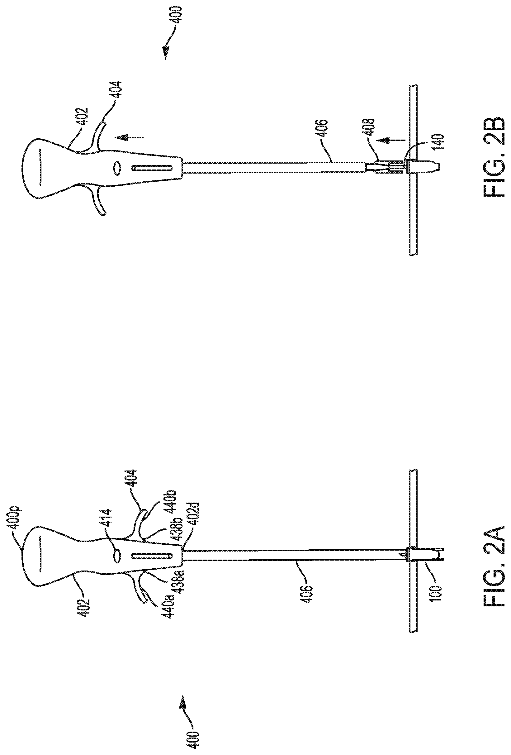
The handle 402 in this embodiment has a generally elongate cylindrical configuration to facilitate grasping thereof. The handle 402 can have a blind bore extending therein from the distal end 402d and terminating just distal to the proximal-most end 400p. The bore can include a guidewire grasping element (not shown) for releasably engaging a guidewire. The grasping element can have a configuration as previously described with respect to FIGS. 1A-1C, or it can have a configuration as described in the aforementioned patent applications which are incorporated herein by reference. A distal portion of the bore can slidably receive the proximal end of the outer shaft 406. The handle 402 can further include elongate longitudinal cut-outs 438a, 438b formed in opposite sidewalls thereof and in communication with the bore. The cut-outs 438a, 438b can allow the actuator 404 to extend therethrough and to slidably move there along.
The actuator 404 in this embodiment is similar to the actuator of FIGS. 1A-1C and is generally T-shaped with distal facing finger-gripping surfaces 440a, 440b. The actuator 404 extends laterally outward from opposed sides of the handle 402, and thus allows a user to place the proximal end 400p of the handle 402 in their palm and to grasp the actuator 404 with one or more fingers to pull the actuator 404 proximally. The actuator can thus slide proximally and distally relative to the handle. The actuator 404 can be fixedly mated to or integrally formed on the proximal end of the outer shaft 406. As a result, movement of the actuator 404 relative to the handle 402 moves the outer shaft 406 relative to the handle 402 (once the lock 414 is released). While not shown, a person skilled in the art will appreciate that the guidewire extends through a lumen in the outer shaft, through a lumen in the actuator, and through the bore in the handle.
As indicated above, the handle can include additional features for controlling movement of the outer shaft 406 relative to the handle 402. As shown in FIGS. 2A-2B, the handle 402 includes a lock 414 disposed thereon. The lock 414 can be actuated by pressing the lock 414 into the handle 402. When in a locked position as shown in FIG. 2A, the lock 414 blocks proximal movement of the actuator 404 and thus locks the outer shaft 406 in a fixed position relative to the handle 402. In order to move the actuator 404 and the outer shaft 406 proximally relative to the handle 402 (thereby retracting the fork 408 relative to the guidewire and the sheath 100), the lock 414 must be moved to an unlocked position, shown in FIG. 2B, in which the actuator 404 is free to move proximally. Movement of the lock between the locked and unlocked positions can be achieved using, for example, a push-button mechanism having a rotating component that alternates between two positions, the locked and unlocked position.
FIGS. 3A-3C show another embodiment of a sheath inserter tool 500 that is similar to the embodiment of FIGS. 2A-2C, but that has a pistol-grip handle assembly. As shown, the tool 500 generally includes a handle 502, an actuator 504 slidably disposed within and extending through the handle 502, and an outer shaft 506 coupled to the actuator 504 and extending within and distally from the handle 502. The outer shaft 506 can include the fork on the distal end thereof, as previously described above with respect to FIGS. 1A-1C.
The handle 502 has a generally elongate cylindrical configuration with a pistol-grip portion to facilitate grasping thereof. The handle 502 can have a blind bore extending therein from the distal end 502d and terminating just distal to the proximal-most end. The bore can be configured to receive the guidewire mated to the sheath, as shown, and a distal portion of the bore can receive the proximal end of the outer shaft 506 for mating the shaft to the actuator. The handle 502 can further include an elongate longitudinal cut-out 538a formed in a sidewall thereof and in communication with the inner lumen. The cut-out 538a can allow the actuator 504 on the inner component to extend therethrough and to slidably move there along.
The actuator 504 is generally trigger-shaped and includes a distal facing finger-gripping surface 540a. The actuator 504 extends laterally outward from a side of the handle 502, and thus allows a user to place the pistol-grip portion of the handle 502 in their palm and to grasp the actuator 504 with one or two fingers to pull the actuator 504 proximally towards the pistol-grip portion of the handle 502. The actuator can thus slide proximally and distally relative to the handle. The actuator 504 can be fixedly mated to or integrally formed on the proximal end of the outer shaft 506. As a result, after the lock 514 is released, movement of the actuator 504 relative to the handle 502 moves the outer shaft 506 relative to the handle 502 and to the guidewire coupled to the sheath 100.
As shown in FIGS. 3A-3C, the handle 502 includes a lock 514 disposed thereon that is similar to the lock 414 of FIGS. 2A-2C. The lock 514 can be moved into a locked position by pushing the lock 514 into the handle 502. When in a locked position as shown in FIG. 3B, the lock 514 prevents proximal movement of the actuator 504 and locks the outer shaft 506 from moving longitudinally with respect to the handle 502. In order to move the actuator 504 and the outer shaft 506 proximally relative to the handle 502 and the guidewire, the lock 514 must be moved to an unlocked position. This can be achieved by pressing the lock 514 so that it moves out and no longer blocks movement of the actuator 504. Proximal movement of the actuator 504 will retract the fork 508 from the sheath 100, as shown in FIG. 3C.
FIGS. 4A-4B show another embodiment of a sheath inserter tool 600. In this embodiment, rather than having an outer shaft with a fork that is moved proximally relative to the guidewire coupled to the sheath, the tool 600 includes an inner component having the fork thereon, and the inner component is moved proximally relative to an outer component and the guidewire. In particular, the tool 600 includes an outer component having a handle 602 with an outer shaft 606 extending distally therefrom, and an inner component that includes an actuator 604 in the form of a finger loop that is coupled to a proximal end of an inner shaft 610 that extends through the handle 602 the outer shaft 606. Movement of the inner shaft relative to the outer shaft is effective to move the fork between an extended position, in which the fork extends beyond a distal end of the outer shaft, and a retracted position, in which the fork is retracted into the outer shaft. Once the sheath is positioned in the bone hole, the lock 614 can be released and the fork can be retracted from the sheath. The distal end of the outer shaft 606 can abut the proximal end of the sheath 100 to maintain the sheath within the bone hole.
The handle 602 in this embodiment has a generally T-shaped configuration with one side being in the form of a finger loop and the other side being in the form of a half-loop having a generally elongated arced shaped. This configuration allows a user to rest one finger, e.g., their pointer finger, against the half-loop, and to insert another finger, e.g., their middle finger, through the finger loop. The finger loop and half-loop that form the handle 602 can be integrally formed on or fixedly mated to a proximal end of the outer shaft 602. Both the outer shaft and the handle 602 can include a central lumen extending therethrough for slidably receiving the inner shaft 610.
The actuator 604, which is positioned proximal to the handle 602 and which is coupled to the inner shaft 610, is generally loop-shaped and is configured to receive, for example, a user's thumb. The actuator 604 can be fixedly mated to or integrally formed on the proximal end of the inner shaft 610. As a result, movement of the actuator 604 relative to the handle 602 moves the inner shaft 610 relative to the outer shaft 606.
As shown in FIGS. 4A-4B, the tool 600 can also include a lock 614 for locking the inner and outer shafts 610, 606 in a fixed position relative to one another. In one embodiment, the lock 614 can be in the form of a removable structure that can be snapped onto the inner shaft 610 and that can also engage a flange or other feature (not shown) formed on a proximal end of the handle 602. When the lock 614 is mated to the inner shaft 610 and the handle 602, the inner and outer shafts 610, 606 are prevented from longitudinal movement. The device can be inserted through tissue or through a cannula in the locked position, and once the sheath is implanted within a bone hole, the lock 614 can be removed by moving the lock 614 laterally away from the device 600. With the lock removed, as shown in FIG. 4B, the actuator 604 and the inner shaft 610 can be moved proximally away from the handle 602 and outer shaft 610, thereby retracting the fork 608 out of the sheath 100 and into the outer shaft 606. The outer shaft 606 can remain in position, pressing the sheath into the bone hole.
FIGS. 5A-B show another embodiment of a sheath inserter tool 700 that functions in a similar manner to the tool of FIGS. 4A-4B, but that includes a different handle assembly. In particular, the tool 700 includes an outer component having a handle 702 with an outer shaft 706 extending therefrom, and an inner component that includes an actuator 704 that is slidably coupled to an inner shaft 710 extending from the actuator 704 and through the handle 702 and the outer shaft 706.
The handle 702 has a generally elongate cylindrical configuration to facilitate grasping thereof. The diameter can remain constant along the length of the handle 702, or a proximal or the handle can taper inward in a proximal direction, and a distal portion of the handle can taper inward in a distal direction, as shown. The handle 702 can have a bore extending entirely therethrough. The bore can be configured to slidably receive the inner shaft therethrough, and a distal portion of the bore can receive the proximal end of the outer shaft 706 for mating the outer shaft to the handle. Various mating techniques as described above can be used to fixedly mate the outer shaft 706 to the handle 702.
The actuator 704 in this embodiment has a conical shape that tapers inward in a distal direction to form a distal facing finger-gripping surface 740a. The actuator 704 is positioned proximal of the handle 702 to thus allow a user to wrap their fingers around the handle, as indicated by the circles, and to place their thumb in the finger-gripping surface 740a to push the actuator 704 proximally upwards away from the handle 702. The actuator can thus slide proximally and distally relative to the handle 702. The actuator 704 can be fixedly mated to or integrally formed on the proximal end of the inner shaft 710. As a result, movement of the actuator 704 relative to the handle 702 moves the inner shaft 710 relative to the outer shaft 706.
As shown in FIGS. 5A-5B, the device 700 further includes a lock 714 disposed on the inner shaft 710 and configured to engage the proximal portion of the handle 702. While not shown, the handle 702 can include a flange or other feature that is engaged by the lock 714 so as to allow the lock 714 to prevent movement of the inner shaft 710 and the handle relative to one another. The lock 714 can alternatively engage the actuator 704, rather than the inner shaft 710, to prevent movement of the inner and outer components relative to one another. When in a locked position as shown in FIG. 5A, the lock 714 prevents proximal movement of the actuator 704 and locks the inner and outer shafts 710, 706 from moving longitudinally with respect to each other. In order to move the actuator 704 and the inner shaft 710 proximally relative to the handle 702 and outer shaft 710, and to thereby retract the fork 708 from within the sheath 100, the lock 714 can be removed from the device, as can be seen in FIG. 5B.
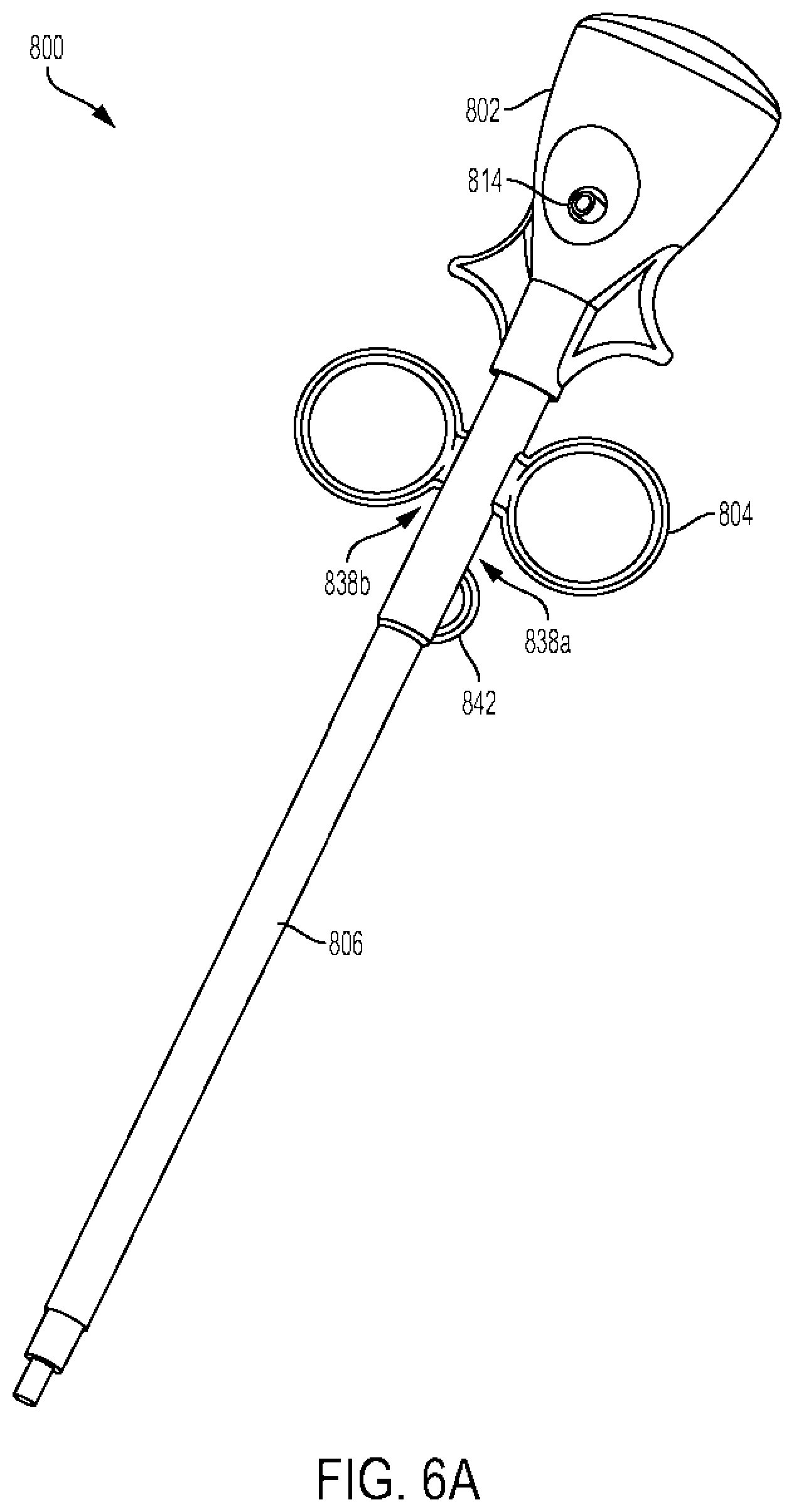
FIGS. 6A and 7 show two additional embodiments of sheath inserter tools 800, 800', each of which includes an outer component having a handle 802, 802' with an outer shaft 806, 806' extending distally therefrom, and an inner component that includes an actuator 804, 804' that is positioned distal of the handle 802, 802' and that is mated to or integrally formed on the inner shaft 810, 810'. The actuator 804, 804' can extend through longitudinal slots in the outer shaft 806, 806', and the inner shaft 810 can be slidably disposed within the outer shaft 806, 806'. While not described in detail, a person skilled in the art will appreciate that the tools of FIGS. 6 and 7 can function as previously described with respect to FIGS. 4A-4B.
Each handle 802, 802' can have a generally conical, knob-like configuration for allowing the handle to sit within a user's palm. The handles 802, 802' can include distal-facing recesses formed therein that are configured to seat the finger loop or loops on the actuator, as will be discussed below. Each handle 802, 802' can also have a blind bore extending therein from the distal end and terminating at a location distal to the proximal-most end. The bore can be configured to receive and releasably mate to a guidewire, as described above with respect to FIGS. 1A-1C. A distal portion of the bore can receive the proximal end of the outer shaft 806 for mating the shaft to the handle. The outer shaft 806 can further include two elongate longitudinal cut-outs 838a, 838b, as shown in FIG. 6A, or only a single cut-out 838a' as shown in FIG. 7, formed in the sidewall thereof and in communication with the inner lumen. The cut-outs 838a, 838b, 838a' can allow the actuator 804 on the inner component to extend therethrough and to slidably move there along.
The actuator 804 in FIG. 6A has first and second finger loops for receiving a user's fingers, e.g., the pointer and middle fingers. The actuator 804' in FIG. 7 only has a single finger loop for receiving a single finger, e.g., a pointer finger or thumb. Each actuator 804, 804' extends laterally outward from a sidewall of the outer shaft 806, 806', and thus allows a user to place the proximal end of the handle 802, 802' in their palm and to grasp the actuator 804, 804' with one or more fingers to pull the actuator 804, 804' proximally. The actuator can thus slide proximally and distally relative to the handle. The actuator 804, 804' can be fixedly mated to or integrally formed on a proximal portion of the inner shaft 810, 810'. Preferably, the inner shaft 810 810' extends proximally beyond the actuator to allow the proximal end of the inner shaft to extend into the handle 802 and to be engaged by the lock 814, discussed below. In use, movement of the actuator 804, 804' relative to the handle 802, 802' moves the inner shaft 810, 810' relative to the outer shaft 806, 806' and relative to a guidewire coupled to the handle 802, 802'.
Each tool can further include a lock 814 extending through the handle 802, as seen in FIG. 6A. While only FIG. 6A illustrates a lock, a person skilled in the art will appreciate that the tool of FIG. 7 can likewise include a lock. The lock 814 is shown in more detail in FIGS. 6B-6D, and is generally in the form of an elongate member having a central opening or elongate cut-out 814c formed therein. As shown in FIG. 6B, the cut-out 814c can include an engagement feature 814e, such as a protrusion or ledge, that is configured to be moved in and out of one or more grooves formed in the proximal end of the inner shaft 810. In an exemplary embodiment, as shown, one end of the lock 814 can include a bump 814a formed therein and the other end of the lock 814 can include a recess 814b formed therein. The engagement feature 814e can be formed within the cut-out 814c at a location adjacent to the bump 814a, such that the bump 814a can indicate the closed positioned, whereas the recess 814b can indicate the open position, as will be discussed in more detail below. As shown in FIG. 6C, the proximal end of the inner shaft 810 can include three grooves 815a, 815b, 815c formed therein and spaced longitudinally there along. The proximal-most groove 815a can correspond to a position in which the inner shaft 810 is fully extended relative to the outer shaft 806, the distal-most groove 815c can correspond to a position in which the inner shaft 810 is fully retracted relative to the outer shaft 806, and the middle groove 815b can correspond to a mid-position between the fully extended and fully retracted positions. A person skilled in the art will appreciate that the inner shaft 810 can include any number of grooves formed therein as may be desired. FIG. 6C illustrates the lock 814 engaged in the middle position with the middle groove 815b, with the bump 814a positioned closer to the inner shaft 810 than the recess 814b. The inner shaft 810 is thus preventing from moving relative to the outer shaft 806. Pressing on the recess 814b to slide the lock 814 relative to the handle 802 will move the engagement feature 814e out of engagement with the groove 815b, thus allowing free slidable movement of the inner shaft 810 relative to the outer shaft 806.
As shown in FIG. 6D, the inner shaft can also include features that resist movement of the inner shaft relative to the outer shaft when the lock 814 is disengaged. Such features can also include the position of the inner shaft relative to the proximal-most, middle, and distal-most positions as defined by the grooves 815a-c. In the illustrated embodiment, a collar 816 is disposed around the proximal end of the inner shaft 806 and it includes opposed elongate slots 817, 819 formed therein. While only slot 817 is discussed, it will be appreciated that slot 819 can include the same features and can function in the same manner. As shown, slot 817 can include a three notches formed therein, a proximal-most notch 817p, a middle notch 817m, and a distal notch 817d. Each notch 81'7p, 817m, 817d can be configured to frictionally engage a pin 810p formed on or coupled to the proximal end of the inner shaft 810, at a location above the grooves 815a-c. The notches can engage the pin to hinder but not prevent movement. Moreover, each notch 81'7p, 817m, 817d can be positioned such that, when the pin 810p is seated therein, the button 814 will be aligned with the corresponding proximal, middle, or distal grooves 815a-c. In order to allow the notches 81'7p, 817m, 817d to engage the pin 810p, the collar 816 can include side slots 821a, 821b formed on opposed sides thereof. The side slots 821a, 821b allow the sidewalls surrounding slot 817 to flex as the pin 810p is moved into a notch 817p, 817m, 817d.
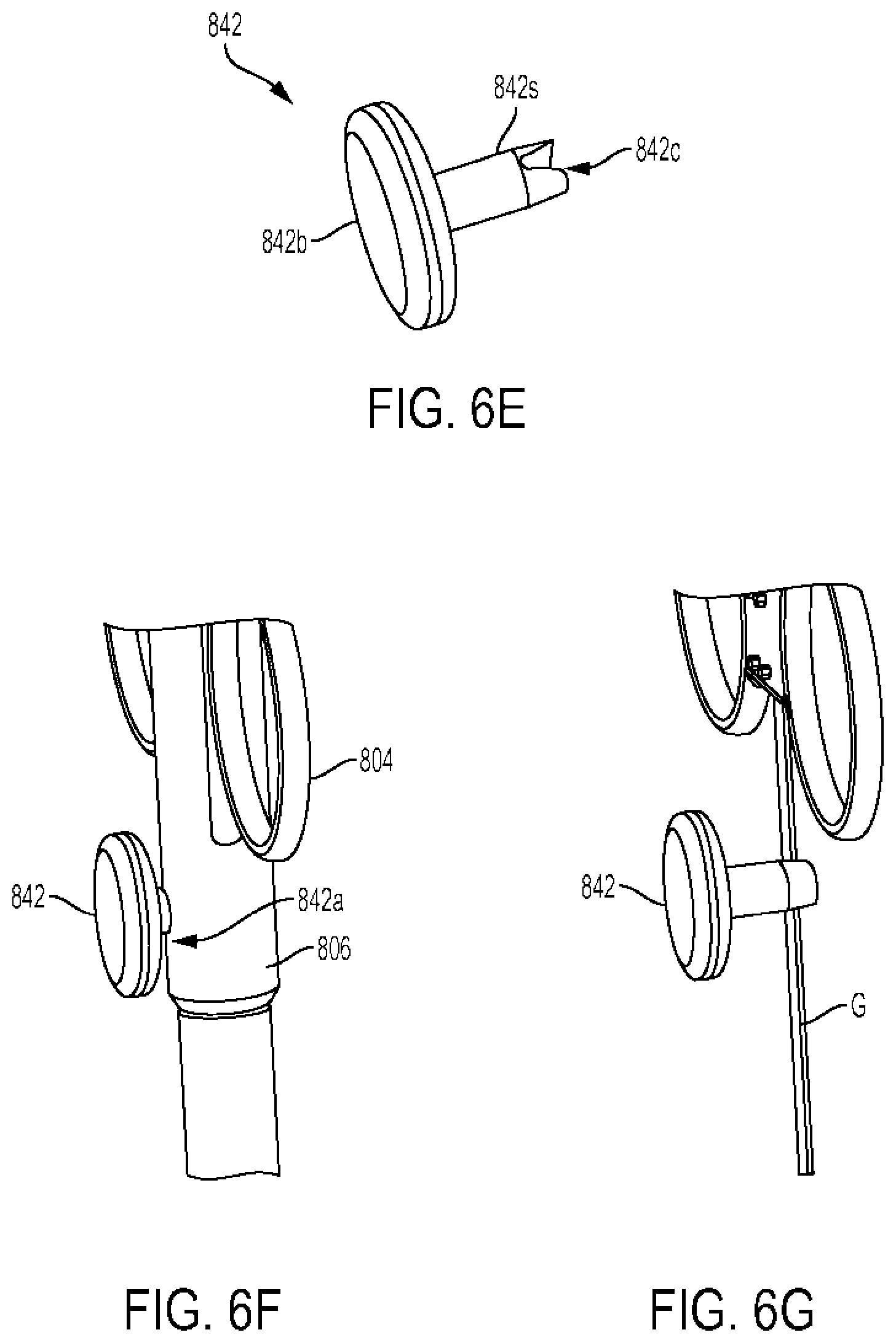
The device can also include a feature for preventing longitudinal movement of the guidewire. FIGS. 6E-6G illustrate a button 842 that is configured to releasably engage the guidewire G extending through the shaft 806. As shown, the button includes a head 842h and shaft 842s extending therefrom. The shaft 842s includes a slot or cut-out 842c formed in the distal end thereof for engaging the guidewire G. The cut-out 842c is configured to snap onto the guidewire G to prevent movement of the guidewire G relative to the button 842. The outer shaft 806 can include an opening 842a formed therein for receiving the button 842. In use, the button 842 can be pressed through the opening 842a to cause the cut-out 842c to engage the guidewire G, and removing the button can release the guidewire G.
FIG. 8 shows another embodiment of a sheath inserter tool 900 that functions in a similar manner as described above. In general, the tool includes an outer component having a handle 902 with an outer shaft 906 extending therefrom, and an inner component that includes an actuator 904 that is coupled to the inner shaft 910, which extends through the handle 902 and the outer shaft 906.
The handle 902 has a generally elongate cylindrical configuration to facilitate grasping thereof. The handle 902 can have a bore extending entirely therethrough. The bore can be configured to slidably receive the inner shaft therethrough, and a distal portion of the bore can receive the proximal end of the outer shaft 906 for mating the shaft to the handle. The handle 902 can further include a side cut-out 938a formed in a sidewall thereof and a top cut-out or opening 938b formed in the proximal-most end thereof. The side cut-out 938a can allow a lateral finger grip 940a to extend therethrough, and the top cut-out 938b can allow a proximal finger grip 940b to extend therethrough.
The actuator 904 is generally conical and includes a biasing element 905 (such as a spring) proximal to the inner shaft 910 in the handle 902 that, in a compressed state, results in the fork 908 being in a fully extended position when the sheath 100 is mated to the tool (as shown in FIG. 8). The actuator 904 can be actuated by pressing the lateral finger grip 940a radially inward toward the handle 902 until the surface 940a is within the handle. This radially inward movement causes the biasing element 905 to be released from the compressed state. The release of the biasing element 905 will cause the biasing element 905 to move proximally to an elongated, relaxed state, which will cause the inner shaft 910 to move proximally with respect to the outer shaft 906 and handle 902, thereby retracting the fork 908 from the sheath 100 and into the outer shaft. After first actuation and as the biasing element 905 of the actuator 904 moves to a relaxed state, the movement will cause the proximal finger grip 940b to move proximally relative to the handle 902.
Distal movement of the proximal finger grip 940b can reverse the retraction, causing the biasing element 905 to re-compress by moving the spring distally into a compressed state until the lateral finger grip 940a can again extend through the cut-out 938a. This movement will cause the inner shaft 910 to move distally again. A user can place the elongate cylindrical configuration of the handle 902 in their palm and manipulate the actuator 904 with, for example, a thumb. The actuator 904 can be fixedly mated to or integrally formed on the proximal end of the inner shaft 910. As a result, movement of the actuator 904 relative to the handle 902 moves the inner shaft 910 relative to the outer shaft 906.
FIG. 9 shows a proximal portion of another embodiment of a sheath inserter tool 1000 that can function as previously described with respect to FIGS. 4A-4B. In this embodiment, the tool 1000 includes an outer component having a handle 1002 with an outer shaft 1006 extending therefrom, and an inner component that includes an actuator 1004 that is slidably disposed relative to the handle 1002 and that is coupled to an inner shaft 1010 extending through the handle and through the outer shaft 1006. While not shown, the distal end can be similar to the aforementioned embodiments, with the inner shaft including a fork thereon as described with respect to FIGS. 1A-1C.
The handle 1002 has a generally elongate cylindrical configuration to facilitate grasping thereof. The handle 1002 can have a blind bore extending therethrough from the distal end 1002d and terminating just distal to the proximal-most end. The bore can be configured to receive a proximal end of a guidewire mated to a sheath. While not shown, the bore can include a guidewire grasper for releasably engaging the guidewire, as discussed above. A distal portion of the bore can receive the proximal end of the outer shaft 1006 for mating the shaft to the handle. The handle 1002 can further include an elongate longitudinal cut-out 1038a formed in a sidewall thereof and in communication with the inner lumen. The cut-out 1038a can allow the actuator 1004 on the inner component to extend therethrough and to slidably move there along.
The actuator 1004 is in the form of a sliding button or knob that includes a finger-gripping surface 1040a. The actuator 1004 extends laterally outward from a side of the handle 1002, and thus allows a user to place the handle 1002 in their palm and to manipulate the actuator 1004 with fingers, for example a thumb, to move the actuator 1004 proximally and distally relative to the handle. The actuator 1004 can be fixedly mated to or integrally formed on the proximal end of the inner shaft 1010. As a result, movement of the actuator 1004 relative to the handle 1002 moves the inner shaft 1010 relative to the outer shaft 1006, thereby retracting a fork on the distal end of the inner shaft from a sheath (not shown) and into a distal end of the outer shaft. Similar to the other embodiments, the handle 1002 can also include a lock (not shown).
FIGS. 10A-10B show another embodiment of a sheath inserter tool 1100 that functions in a similar manner to the aforementioned embodiments, and that generally includes an outer component having a handle 1102 with an outer shaft 1106 extending therefrom, and an inner component that includes an actuator 1104 that is positioned proximal to the handle 1102 and that is coupled to a proximal end of an inner shaft 1110 extending through the handle 1102 and through the outer shaft 1106.
The handle 1102 has a generally elongate cylindrical configuration to facilitate grasping thereof. The handle 1102 can have a bore extending entirely therethrough for receiving the inner shaft. A distal portion of the bore can receive the proximal end of the outer shaft 1106 for mating the shaft to the handle. The bore can allow the actuator 1104, or a portion thereof, on
D00000
D00001
D00002
D00003
D00004
D00005
D00006
D00007
D00008
D00009
D00010
D00011
D00012

D00013

D00014

D00015

D00016

D00017

D00018

D00019

D00020

D00021

D00022

D00023

D00024

D00025

XML
uspto.report is an independent third-party trademark research tool that is not affiliated, endorsed, or sponsored by the United States Patent and Trademark Office (USPTO) or any other governmental organization. The information provided by uspto.report is based on publicly available data at the time of writing and is intended for informational purposes only.
While we strive to provide accurate and up-to-date information, we do not guarantee the accuracy, completeness, reliability, or suitability of the information displayed on this site. The use of this site is at your own risk. Any reliance you place on such information is therefore strictly at your own risk.
All official trademark data, including owner information, should be verified by visiting the official USPTO website at www.uspto.gov. This site is not intended to replace professional legal advice and should not be used as a substitute for consulting with a legal professional who is knowledgeable about trademark law.