System and method for detection of transmission facilities
Noonan
U.S. patent number 10,708,752 [Application Number 15/694,909] was granted by the patent office on 2020-07-07 for system and method for detection of transmission facilities. This patent grant is currently assigned to Binj Laboratories, Inc.. The grantee listed for this patent is Binj Laboratories, Inc.. Invention is credited to Joseph S. Noonan.

View All Diagrams
| United States Patent | 10,708,752 |
| Noonan | July 7, 2020 |
System and method for detection of transmission facilities
Abstract
In embodiments, a method of detecting a transmitting device within an obstruction rich environment is disclosed. The method may involve detecting the transmitting device with a wireless transmission detection facility; communicating signal information relating to the detected transmitting device from the wireless transmission detection facility to a central unit; determining the location of the transmitting device; displaying information of the detection and location of the transmitting device through a user interface; and providing an action facility for causing actions related to the detected transmitting device.
| Inventors: | Noonan; Joseph S. (Scituate, MA) | ||||||||||
|---|---|---|---|---|---|---|---|---|---|---|---|
| Applicant: |
|
||||||||||
| Assignee: | Binj Laboratories, Inc.
(Scituate, MA) |
||||||||||
| Family ID: | 59701229 | ||||||||||
| Appl. No.: | 15/694,909 | ||||||||||
| Filed: | September 4, 2017 |
Related U.S. Patent Documents
| Application Number | Filing Date | Patent Number | Issue Date | ||
|---|---|---|---|---|---|
| 15000173 | Sep 5, 2017 | 9756498 | |||
| 13300560 | Jan 19, 2016 | 9241251 | |||
| 11457786 | Dec 13, 2011 | 8078190 | |||
| 60699281 | Jul 14, 2005 | ||||
| 60739877 | Nov 23, 2005 | ||||
| Current U.S. Class: | 1/1 |
| Current CPC Class: | H04W 40/06 (20130101); H01Q 21/28 (20130101); H01Q 1/007 (20130101); H04B 17/318 (20150115); H04W 8/005 (20130101); G01S 5/02 (20130101); H04W 64/00 (20130101); Y02D 30/70 (20200801); H04W 48/04 (20130101); H04W 64/006 (20130101) |
| Current International Class: | H04W 24/00 (20090101); H04W 8/00 (20090101); G01S 5/02 (20100101); H01Q 21/28 (20060101); H04W 40/06 (20090101); H01Q 1/00 (20060101); H04W 64/00 (20090101) |
References Cited [Referenced By]
U.S. Patent Documents
| 5966655 | October 1999 | Hardouin |
| 6222458 | April 2001 | Harris |
| 6359582 | March 2002 | MacAleese et al. |
| 6580372 | June 2003 | Harris |
| 6765492 | July 2004 | Harris |
| 7202798 | April 2007 | Harris |
| 8989766 | March 2015 | Noonan |
| 2002/0080954 | June 2002 | Rebhan |
| 2002/0098850 | July 2002 | Akhteruzzaman |
| 2003/0206112 | November 2003 | Harris |
| 2004/0113755 | June 2004 | Ricci |
| 2004/0246139 | December 2004 | Harris |
| 2006/0099968 | May 2006 | Harris |
| 2006/0105758 | May 2006 | Maislos |
| 2006/0158316 | July 2006 | Eckstein |
| 2006/0192709 | August 2006 | Schantz |
| 2010/0176918 | July 2010 | Turner |
Attorney, Agent or Firm: Law Office of Carl Giordano, PC.
Parent Case Text
CLAIM OF PRIORITY
This application claims the benefit of the earlier filing date, pursuant to 35 USC 120, as a Continuation of that patent application entitled, "Systems and Method for Detection of Transmission Facilities," filed on Jan. 19, 2016 and afforded Ser. No. 15/000,173, which claimed as a Continuation-in-Part of that patent application entitled "Systems and Methods for Detection of Transmission Facilities," filed on Nov. 19, 2011 and afforded Ser. No. 13/300,560, which claimed as a Divisional application priority to and the benefit of the earlier filing date of that patent application entitled "Systems and Methods for Detection of Transmission Facilities," filed on Jul. 14, 2006 and afforded Ser. No. 11/457,786 (now U.S. Pat. No. 8,078,190) which claimed the benefit of U.S. App. No. 60/699,281, filed on Jul. 14, 2005 and U.S. Provisional Appl. No. 60/739,877 filed on Nov. 23, 2005. The entire contents of these applications is incorporated herein by reference.
Claims
What is claimed is:
1. A method, operable in communication system, for identifying and managing non-transmitting wireless devices, comprising the steps of: outputting a plurality of signals in a frequency band associated with a communication technology; receiving a reflection signal corresponding to selected ones of said outputted plurality of signals, said reflection signal being associated with said outputted plurality of signals not absorbed by said non-transmitting wireless devices; organizing the reflection signals to form a pattern of reflection signals; determining a null within the pattern of reflection signals, wherein the null is determined as received reflection signals having an amplitude value less than an expected result; matching the determined null with at least one predetermined null pattern, wherein said at least one predetermined null pattern being associated with an identity of a signal carrier associated with wireless devices; and identifying a signal carrier associated with a non-transmitting wireless device based on the determined null matching a corresponding one of the predetermined null patterns.
2. A system for identifying and managing wireless devices comprising: a transceiving system; and a processor configured to: cause the transceiving system to transmit a plurality of signals in a frequency band associated with a communication technology; receive a return signal from said plurality of frequencies, said return signals produced by a reflections of the transmitted plurality of signals not absorbed by an antenna associated with a non-transmitting wireless device; form a pattern of the received return signals; determine a null within said pattern of received return signals, wherein said null represents return signals having an amplitude value less than an expected value; compare the null in the pattern of received return signals with a plurality of predetermined null patterns, wherein each of the plurality of predetermined null patterns being associated with a signal carrier of wireless devices; and identify said wireless device with a signal carrier based on one of said plurality of predetermined null patterns matching said determined null.
3. The system of claim 2, wherein transmitting the plurality of signals is performed in manner that is one of: discreetly, sequentially, and randomly.
4. The system of claim 2, wherein the plurality of signals are transmitted in one of a plurality of frequency bands associated with a communication technology.
5. The system of claim 2, wherein the plurality of signals are transmitted in a plurality of the plurality of frequency bands concurrently.
6. A system for identifying a wireless device comprising: a transmitter configured to transmit a plurality of signals in a frequency band defined by a first frequency and a second frequency; a receiver configured to receive return signals corresponding to the plurality of transmitted signals, wherein said return signals represent reflections of said plurality of transmitted signals; and a processor configured to: generate a pattern comprising the received return signals; determine a null within the pattern of received return signals, wherein the null represents selected ones of the plurality of transmitted signals not absorbed by the wireless device; compare the generated pattern of received return signals to a plurality of predetermined patterns, said predetermined patterns corresponding to known signal carriers; and assign the wireless device to one of said known signal carriers having a predetermined pattern matching said determined null.
7. The system of claim 6, further comprising: transmitting said plurality of signals in a plurality of frequency bands.
8. The system of claim 6, wherein said plurality of signals are transmitted in a manner comprising one of: sequentially and randomly.
9. The system of claim 6, further comprising: outputting an indication of the null.
10. The system of claim 6, further comprising: outputting the signal carrier identification y of the wireless device.
Description
BACKGROUND
1. Field
This invention relates to location of transmission facilities and more particularly to the location of transmission facilities, such as cellular phones, in correctional institutions.
2. Background
There are many facilities, such as government buildings, and in particular correctional facilities, such as prisons, that do not permit cellular phone usage on the premises or even possession of cell phones in the premises. Finding and preventing usage of cell phones and other transmission facilities is difficult, and a need exists for improved methods of locating such devices, as well as a need for detecting such devices upon ingress to a facility.
SUMMARY
Provided herein are methods and systems for locating transmission facilities such as cell phones, mobile phones, satellite phones, radios, transmitters, PDAs, beepers, pagers, walkie-talkies, email devices, instant messenger devices, voice over IP devices, and other types of wireless communication or transmission facilities.
Embodiments relate to locating and managing the use and presence of wireless communication facilities. Embodiments relate to detecting such devices when they transmit a signal. Other embodiments relate to detecting non-active transmission facilities.
In certain embodiments the methods and systems disclosed herein include methods and systems for detecting a transmitting device within an obstruction rich environment. The methods and systems may include detecting the transmitting device with a wireless transmission detection facility; communicating signal information relating to the detected transmitting device from the wireless transmission detection facility to a central unit; determining the location of the transmitting device; displaying information of the detection and location of the transmitting device through a user interface; and providing an action facility for causing actions related to the detected transmitting device. In embodiments, the wireless transmission detection facility is an antenna. In embodiments, the antenna is a dual dipole embedded antenna. In embodiments, the dual dipole embedded antenna is tuned to receive cell phone transmissions. In embodiments the dual dipole embedded antenna is tuned to receive a frequency band of approximately 700 to 950 MHz. In embodiments the dual dipole embedded antenna is tuned to receive a frequency band of approximately 1.7 to 2.0 GHz. In embodiments the dual dipole antenna is tuned to receive signals in frequency bands of approximately 700 to 950 MHz and 1.7 to 2.0 GHz. In embodiments the obstruction rich environment is a correctional facility. In embodiments the obstruction rich environment is a mall. In embodiments communicating the information relating to the detected transmitting device from the wireless transmission detection facility to a central unit involves wireless communications. In embodiments the wireless communications are 802.11 communications. In embodiments determining the location of the transmitting device is accomplished through transmission triangulation. In embodiments location of the transmitting device is accomplished through a known location of a single antenna.
BRIEF DESCRIPTION OF FIGURES
The systems and methods described herein may be understood by reference to the following figures:
FIG. 1 shows a transmission detection, identification, and reporting system.
FIG. 2 illustrates a system for detecting a transmission facility
FIG. 3 illustrates antenna configurations.
FIG. 4 illustrates a system for detecting a transmission facility in a cell environment.
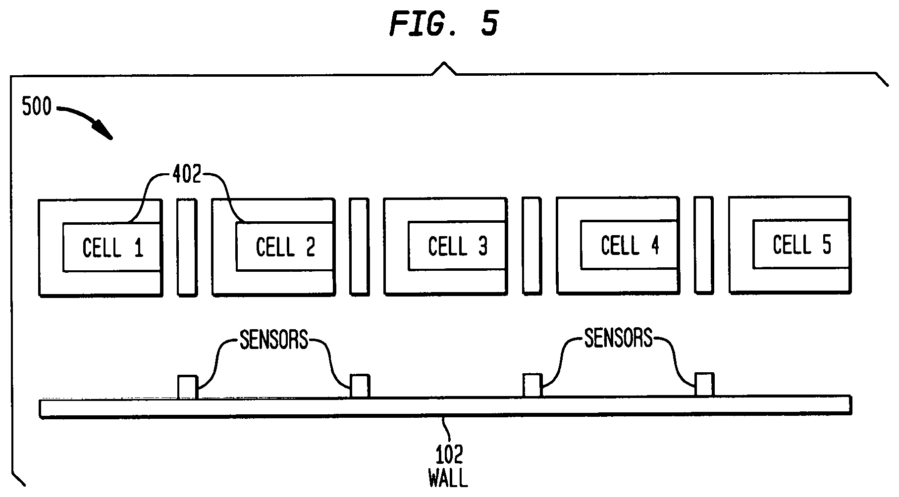
FIG. 5 shows a system for detecting a transmission facility in a cell environment.
FIG. 6 illustrates a block diagram relating to actions taken when detecting transmission facilities.
FIG. 7 shows a transmission facility detection system wherein an antenna array is used to calculate location.
FIG. 8 shows a transmission facility detection system wherein a signal source is differentiated between two adjacent rooms.
FIG. 9 illustrates a transmission facility detection system wherein multiple antennas are used to identify the location of a signal source after an omni-directional antenna has detected its presence.
FIG. 10 shows a schematic diagram of a system for detecting signals of a transmission facility.
FIG. 11 shows a schematic diagram of an alternate embodiment of a system for detecting a signal of a transmission facility.
FIG. 12 shows a schematic diagram of a main circuit board within a system for detecting transmission facilities.
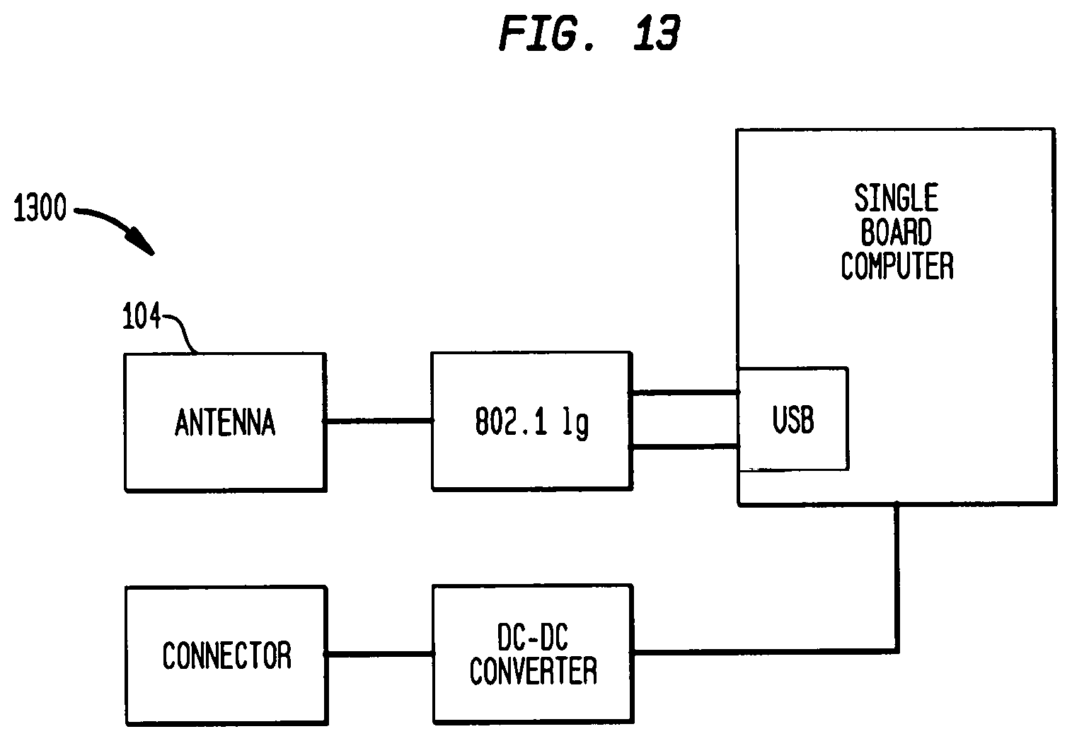
FIG. 13 shows a schematic diagram of a sub-station in a system for detecting transmission facilities.
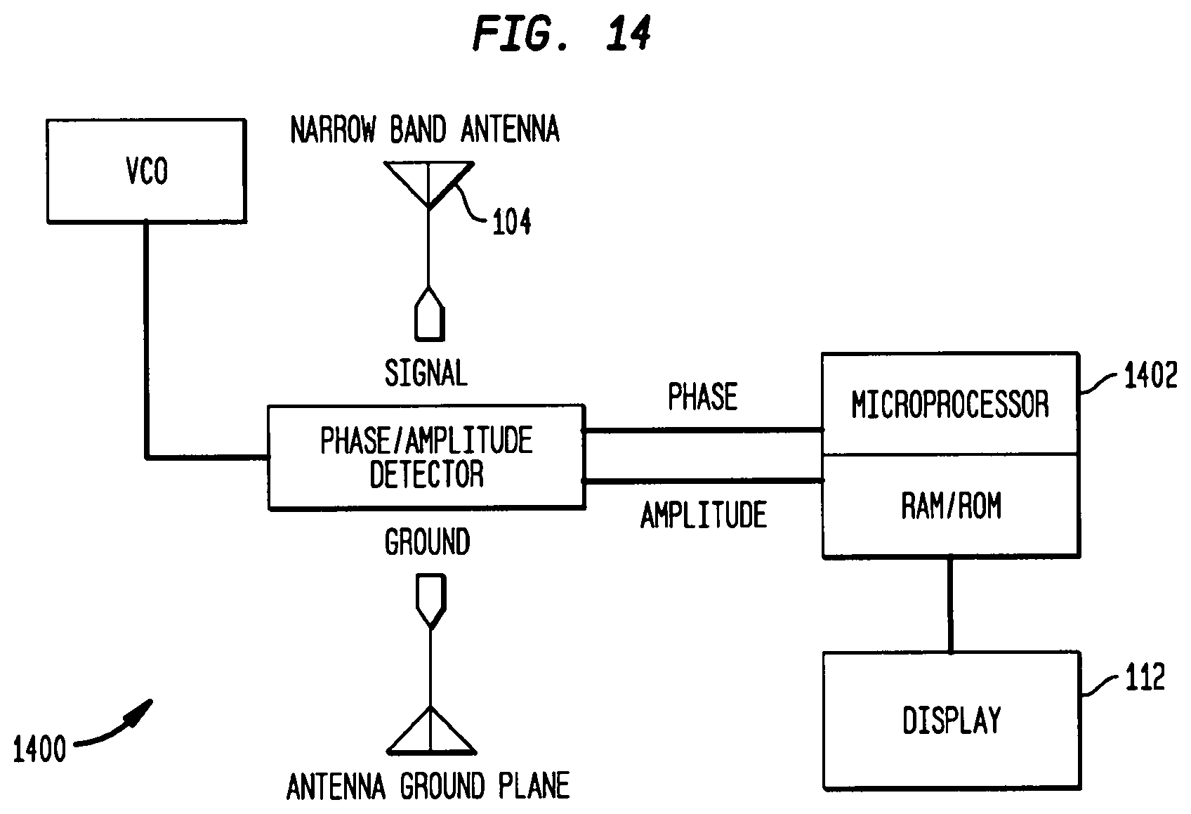
FIG. 14 illustrates a null detection facility.
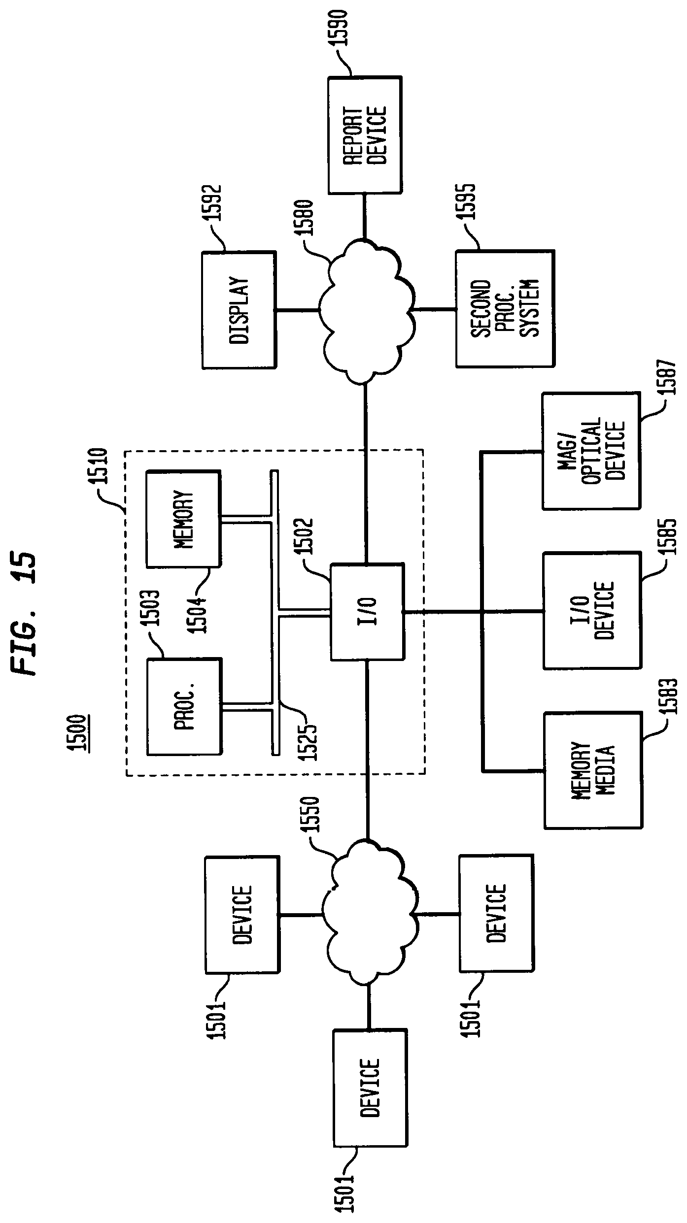
FIG. 15 illustrates a system for implementing the processing shown herein.
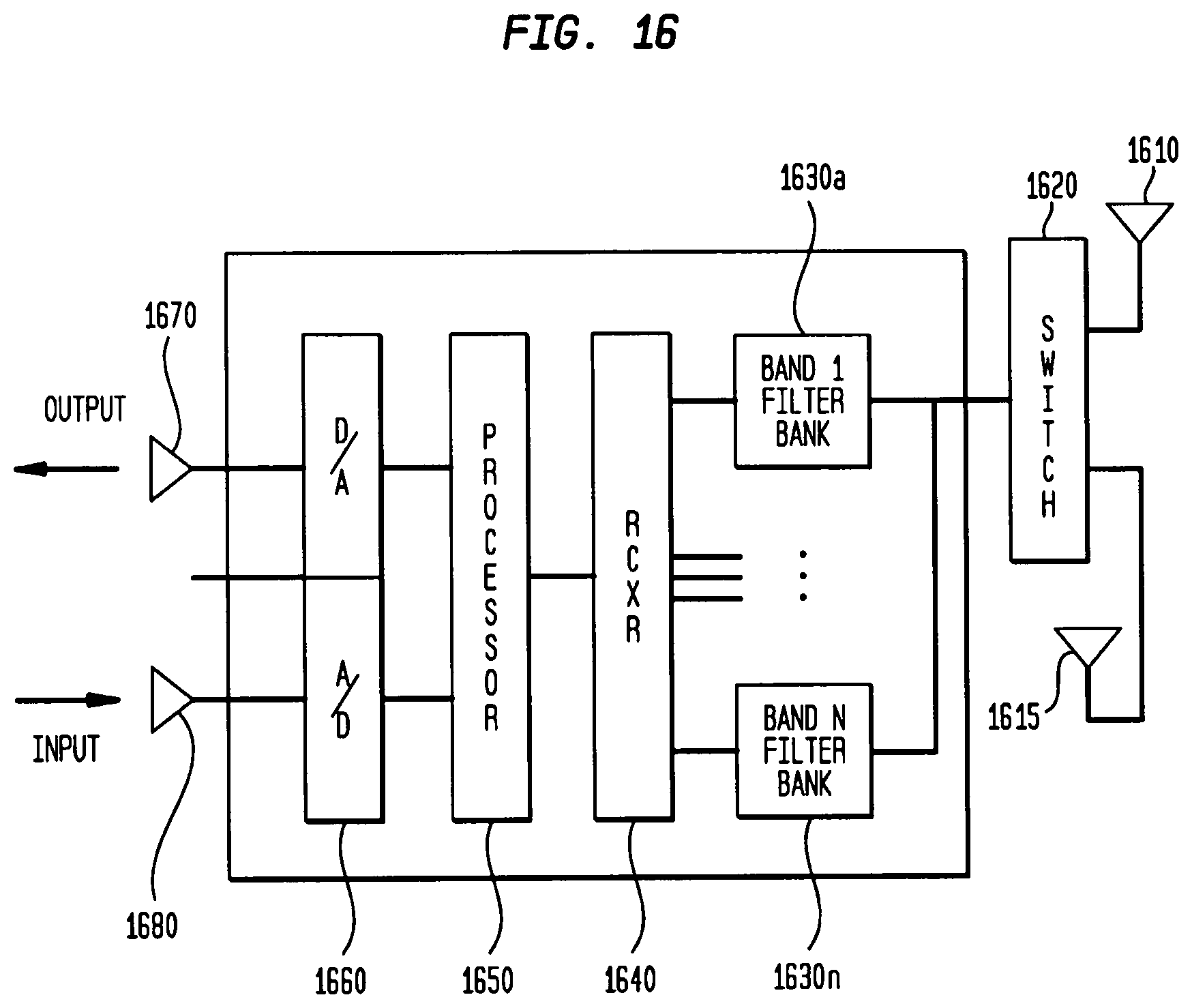
FIG. 16 illustrates a conventional mobile device.
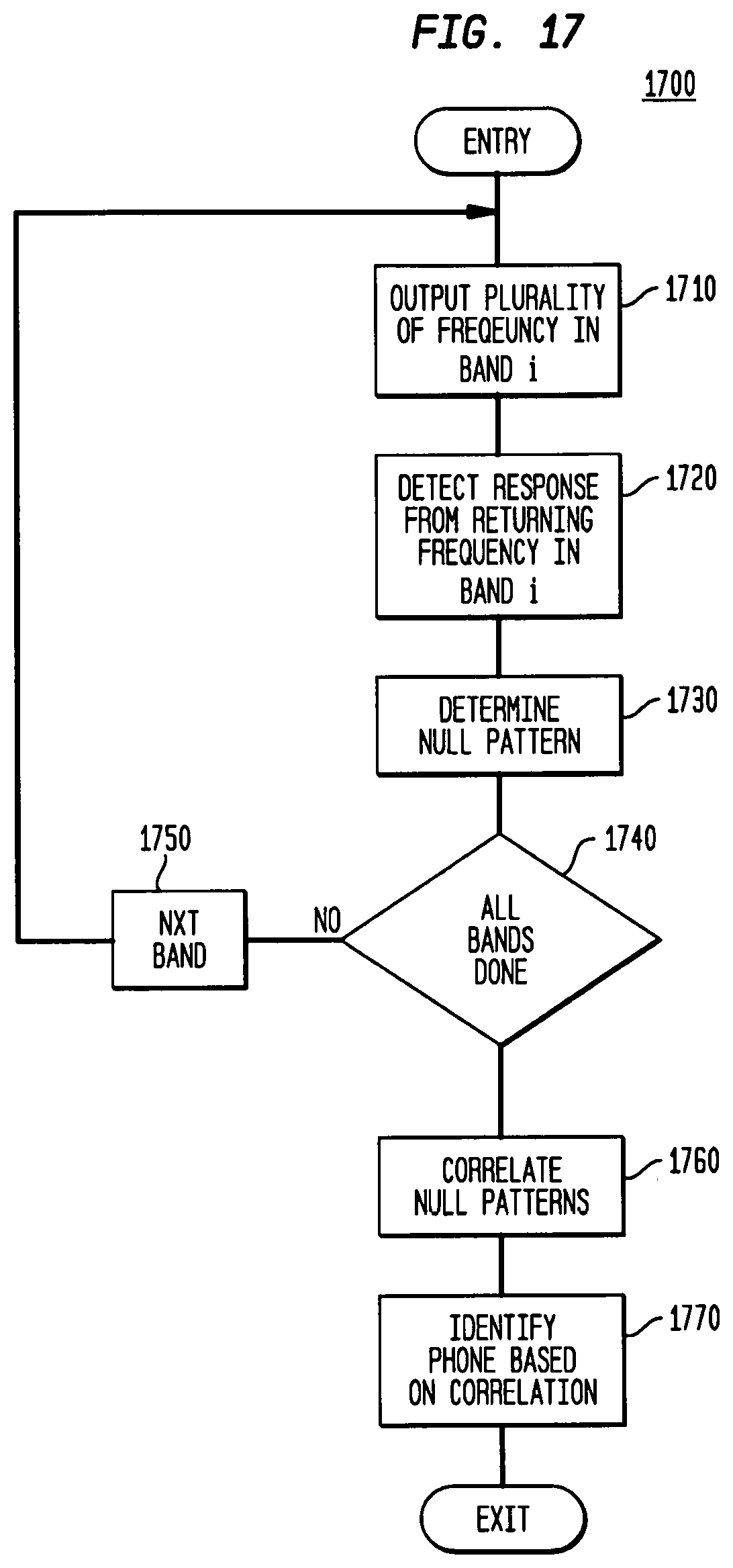
FIG. 17 illustrates a flow chart of a processing in accordance with the principles of the invention.
DETAILED DESCRIPTION OF FIGURES
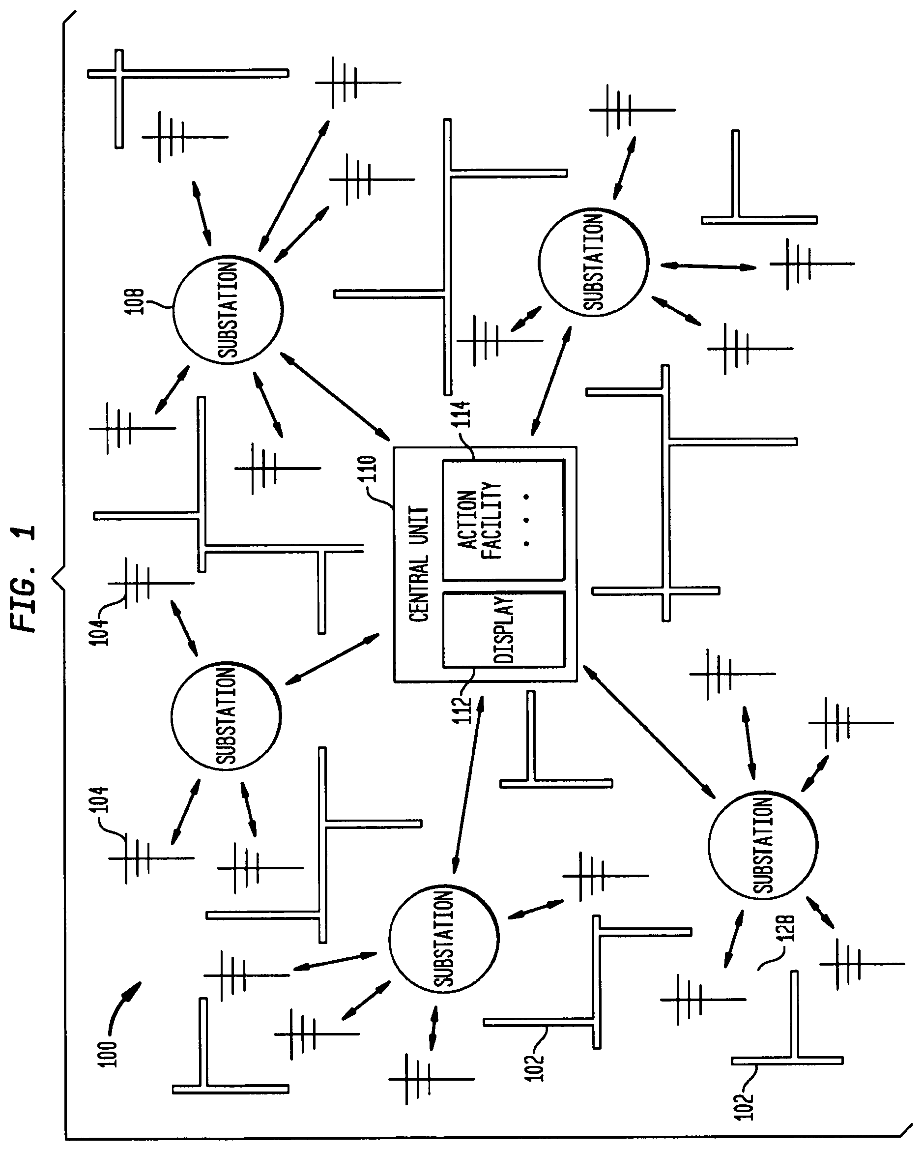
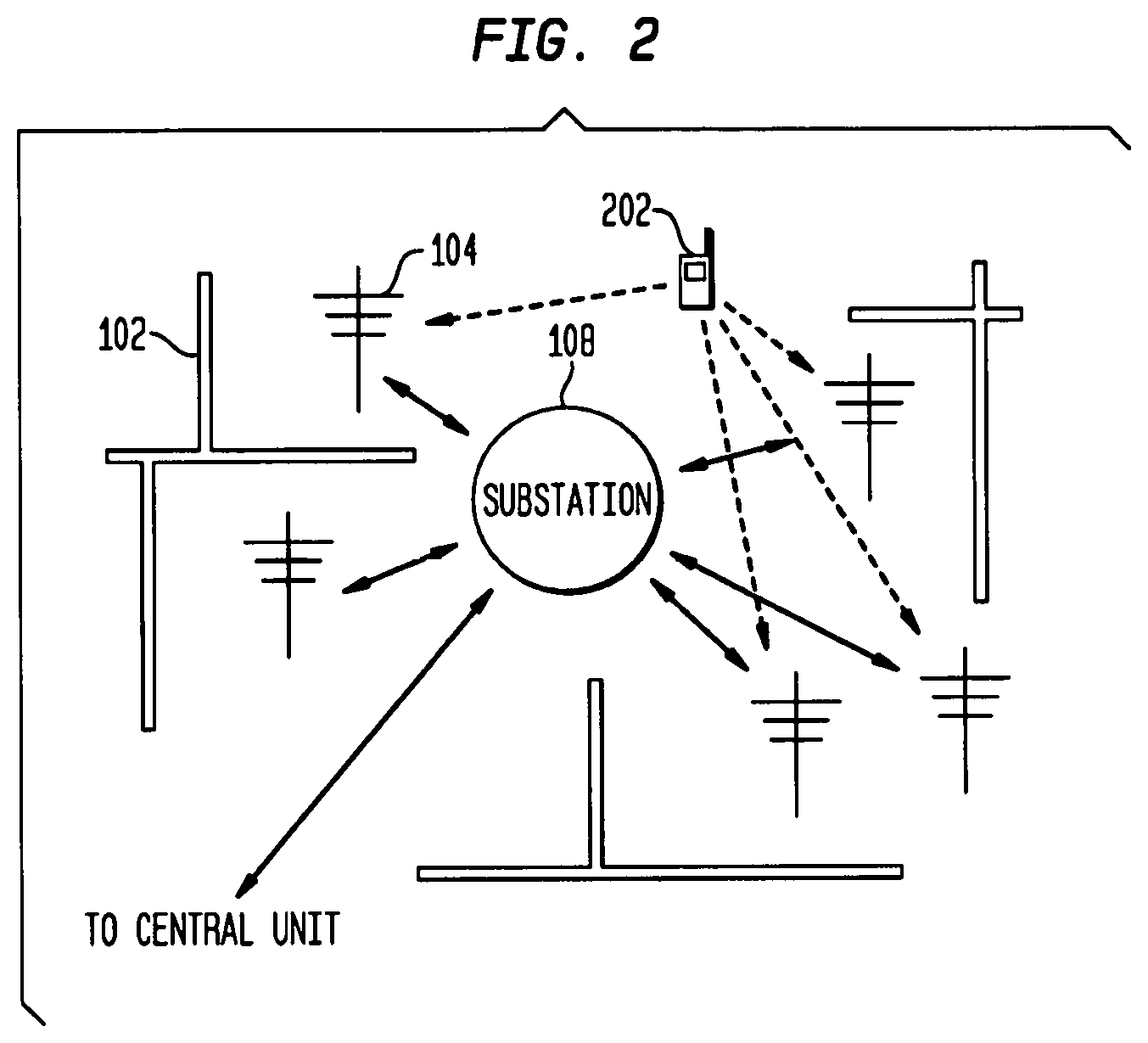
Detection of a transmission facility, such as a mobile phone or hand-held radio transmitter, or other transmission facility as described herein, within an obstruction rich environment, such as a facility with many physical barriers to electronic transmission, is difficult to achieve. Referring to FIG. 1, the transmission detection, identification, and reporting system 100 described herein provides a method of detecting a transmission facility 202, such as depicted in FIG. 2, within an environment rich in obstructions 102. One embodiment of the transmission detection, identification, and reporting system 100 may involve the detection of a mobile phone within a heavily walled and metal-barred government facility such as a correctional facility. In this embodiment, the system may utilize an array of antennas 104 selectively placed within the facility, collection substations 108 for localized collection of detected signals, a central unit 110 for the processing of incoming signals from the facility, a display 112 for showing the location of the detected transmission facility 202, and an action facility 114 for implementing standard procedures in the event of a detection. In this embodiment, the communications between the antennas 104 and the substations 108, and between the substations 108 and the central unit 110, may be wireless to make installation and maintenance of the system within the facility, cost and time effective. Selective placement of the antennas 104, combined with algorithms and methods for determining location of the transmission facility 202, may allow a substantially improved means for locating transmission facilities 202, such as mobile phones, in an otherwise heavily shielded environment.
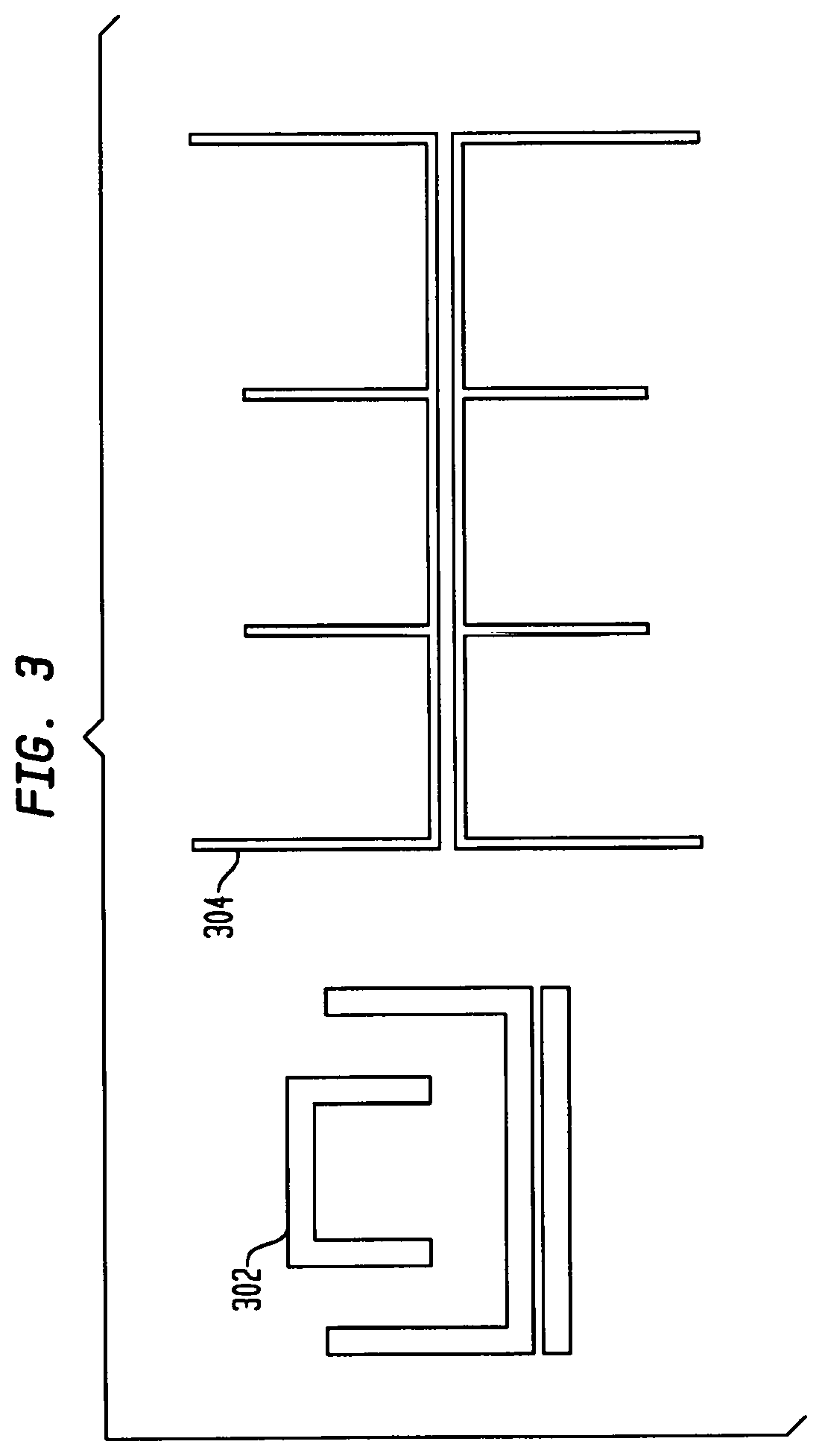
In embodiments the antenna 104 may be a multi-dipole embedded antenna. Two examples of dual dipole embedded antennas are provided in FIG. 3 as a first dual-dipole embedded antenna 302 and a second dual dipole embedded antenna 304. In embodiments the antenna may be adapted to receive one, two, three, four, or more bandwidths. In embodiments the antenna 104 may be a dipole antenna 104, a Yagi-Uda antenna 104, a loop antenna 104, a quad antenna 104, a micro-strip antenna 104, a quad antenna 104, a helical antenna 104, a phase array antenna 104, a patch antenna or the like.
In embodiments, the transmission facility 202 may be a mobile phone, such as a flip phone, a slide phone, a cellular phone, a handset, a satellite phone, a 3G phone, a wireless phone, a cordless phone or the like. In embodiments, the transmission facility 202 may be a radio, such as a walkie-talkie, a mobile radio, a short-wave radio, or the like.
In embodiments, the transmission band from the transmission may be within the radio or other electromagnetic frequency spectrum, such as extremely low frequency (ELF), super low frequency (SLF), ultra low frequency (ULF), very low frequency (VLF), low frequency (LF), medium frequency (MF), high frequency (HF), very high frequency (VHF), ultra high frequency (UHF), super high frequency (SHF), extremely high frequency (EHF), microwave, a frequency suitable for 802.11x wireless communications, ultra wide band (UWB), Bluetooth, or the like.
In embodiments, the obstruction 102 rich environment may be a building, such as a corrections facility, a school, a government facility, a store, a mall, a residence, a hotel, a motel, or the like. In embodiments, the obstruction 102 rich environment may be a large confined space, such as a courtyard, a food court, a recess area, a hallway, greenhouse, recreation room, gymnasium, auditorium, kitchen, cafeteria, craft area, work area, library, prison yard, or the like. In embodiments, the obstruction 102 may be a transmission, device transmission obstruction 102, such as cinderblock, cement, rebar, wire cage, metal, metal coated surface, or the like. In embodiments, the obstruction 102 may be other construction materials, such as wood, glass, rug, flooring materials, roofing materials, and the like.
In embodiments, the transmitting signal information from the antenna 104 module to the central unit 110 may be through a communications connection, such as an IEEE 802.15.4 wireless network, IEEE 802.11 Wi-Fi, Bluetooth, Ethernet, or the and the like. In embodiments, the communications connection may utilize CAT-5, RJ-45, RS-232 connections, and the like. In embodiments the communications connection may utilize an optical connection, such as a wireless infrared link, an optical fiber, and the like.
In embodiments, the transmitting signal information from the antenna 104 module to the central unit 110 may contain data, such as CDMA, CDPD, GSM, TDMA, and the like, and may be used to discriminate which service signal is being used, such as Verizon, Cingular, T-Mobile, Sprint, and the like. The detection of the cell phones may be resolved down to cell phone manufacturer and cell phone provider.
In embodiments, the transmitting signal information to the central unit 110 may be made through an intermediate connection, such as a substation 108, router, switch, hub, bridge, multiplexer, modem, network card, network interface, processing unit, preprocessor, computer, repeater, antenna 104, and the like.
In embodiments, the central unit 110 may have in part a computer, a computer system, a network of computers, a state machine, a sequencer, a microprocessor, a digital signal processor, an audio processor, a preprocessor, a microprocessor, and the like.
In embodiments, the central unit 110 may process information, such as location information, such as the location of people, inmates, corrections personnel, visitors, all personnel within the facility, equipment, resources, weapons, products, incoming goods, outgoing goods, and the like. In embodiments, the information may be type of signal, such as mobile phone standard protocols such as CDMA, CDPA, GSM, TDMA, and the like. In embodiments, the information may be an event notification, such as personnel under duress, an emergency medical condition, a call for assistance, a fire, a call for police, a theft, and the like. In embodiments, the processed information may allow for the tracking of the person or object in possession of the transmission facility 202, such as a mobile phone, a radio, a weapon, a product, a resource, and the like. In embodiments, the processed information may allow for the discrimination and/or association between people or objects, such as determining the ownership of the transmission facility 202, the assignment of the source of transmission, current location of a transmission facility 202 compared to its predicted location, and the like. In embodiments, the processed information may also have time codes and unique identifiers assigned.
In embodiments, the central unit 110 may have a display 112, such as a cathode ray tube (CRT), liquid crystal display 112 (LCD), electronic paper, 3D display 112, head-mounted display 112, projector, segmented display 112, computer display 112, graphic output display 112, and the like. In embodiments, the central unit 110 may have an action facility 114, comprising a user interface for causing actions relating to the detected transmission facility 202, such as closing a door, sealing a room, deploying and action signal, initiating an alarm, and the like.
In embodiments the functions of a central unit 110 as described herein may be replaced by an alternate configuration, such as a configuration of multiple computers, such as a group of servers, processors, or the like, operating in parallel. In embodiments the methods and systems described herein may involve locating computing capabilities in alternative network configurations, such as in a mesh network or a peer-to-peer network.
In embodiments, the location of a transmission facility 202 may be determined by various radiolocation or signal measurement techniques, including measuring phase, amplitude, time, or a combination of these; or by identifying and locating an area associated with an antenna 104 with the highest signal strength. In embodiments, the location of a transmission facility 202 may be determined when the transmission facility 202 is powered off though detection of a null in the band pass of a transmitted frequency sweep due to the presence of a mobile phone antenna.
In embodiments, a method of detecting a transmission facility 202 (e.g. cell phone) when the transmission facility 202 is not powered may require a transmitting device and a receiving device that can recognize the signature of an antenna 104 associated with the transmission facility 202. By transmitting a known frequency and receiving the disturbance pattern produced by having a particular antenna 104 design in the transmission path, the pattern or `signature` of that antenna 104 can be characterized. In embodiments, this characterization may be evaluated with a microprocessor 1402 with results output to a display 112. A database of these signatures can be placed into the device, and as the transmitter sweeps across the various cell frequencies, a pattern received can be matched against the database patterns to determine the presence of transmission facilities 202. In embodiments, any class of antenna (e.g. WI-FI, Blackberry, Walkie-Talkie, etc.) can be classified and identified.
In embodiments, the range of a hand held device that can detect an inactive transmission facility is approximately 10 feet. In embodiments, greater distances could be attained for stationary units by increasing the power.
Radiolocation, also referred to as radio-determination, as used herein encompasses any process of finding the location of a transmitter by means of the propagation properties of waves. The angle at which a signal is received, as well as the time it takes to propagate, may both contribute to the determination of the location of the transmission facility 202. There are a variety of methods that may be employed in the determination of the location of a transmission facility 202. Methods include (i) a cell-sector system that collects information pertaining to cell and sector ID's, (ii) the assisted-global positioning satellite (GPS) technology utilizing a GPS chipset in a mobile communication facility, (iii) standard GPS technology, (iv) enhanced-observed time difference technology utilizing software residing on a server that uses signal transmission of time differences received by geographically dispersed radio receivers to pinpoint a user's location, (v) time difference of arrival, (vi) time of arrival, (vii) angle of arrival, (viii) triangulation of cellular signals, (iix) location based on proximity to known locations (including locations of other radio-transmitters), (ix) map-based location, or any combination of any of the foregoing, as well as other location facilities known to those of skill in the art.
Obstructions 102 to radio wave propagation may greatly reduce the effectiveness of many of the conventional radiolocation methods due to obstruction of the line-of-sight between the transmission facilities 202 and the receiving antennas 104. However, by employing a large array of antennas 104, positioned so as to maintain line-of-sight between possible transmission facility 202 locations and the receiving antennas 104, several of these methods may be effectively used in the location of the transmission facility 202. These methods include time difference of arrival, time of arrival, and angle of arrival, amplitude comparison, and the like. The time difference of arrival method determines the difference in the time, or the difference in phase, of the same radio-transmitting signal arriving at different receiving antennas 104. Together with the known propagation speed of the radio wave, allows the determination of the location of the transmission facility 202. The time of arrival method determines the absolute time of reception of the signal at different receiving antennas 104, and again, along with the known propagation speed of the radio wave, allows the determination of the location of the transmission facility 202. The angle of arrival method utilizes direction of transmission to different antennas 104 to determine the location of the transmission facility. Amplitude comparison method compares the strength of the signal detected at each antenna to determine the location of a transmission facility 202. For example, two antennas 104 located in the same room would detect different signal amplitudes for the same transmission facility 202 output, thereby providing a means of determining which antenna 104 the transmission facility 202 is closer to. Increasing the number of antennas 104 therefore increases the resolution with which the location of the transmission facility 202 may be determined. All of these methods, and combinations of these methods, may employ mathematical processes such as triangulation, trilateration, multilateration, or like, in determining the location of the transmission facility.
Triangulation is the process of finding coordinates and distance to a point by calculating the length of one side of a triangle, given measurements of angles and/or sides of the triangle formed by that point, such as the target transmission facility 202, and two other known reference points, such as the receiving antennas 104. The calculation of the location of the transmission facility 202 may then be performed utilizing the law of sines from trigonometry. Tri-lateration is a method similar to triangulation, but unlike triangulation, which uses angle measurements, together with at least one known distance, to calculate the subject's location, tri-lateration uses the known locations of two or more reference points and the measured distance to the subject, such as the transmission facility 202, and each reference point, such as the receiving antennas 104. Multi-lateration, or hyperbolic positioning, is similar to tri-lateration, but multi-lateration uses measurements of time difference of arrival, rather than time of arrival, to estimate location using the intersection of hyperboloids.
While several radiolocation and triangulation techniques have been described in connection with locating the transmitting device, it should be understood that one skilled in the art would appreciate that there are other location methodologies and such location methodologies are encompassed by the present invention. For example, in embodiments, the location of a single antenna may be known and the single antenna may detect a transmitting device. The location of the transmitting device may be estimated through its known proximity to the single antenna location. This may provide adequate location resolution for certain applications of the technology. Similarly, two or more antennas may be used and each of the antenna locations may be known. When each of the antennas receives a transmission, the corresponding signal strengths may be compared. The one with the highest signal strength may be determined as the one closest to the transmitting device so the corresponding antenna location may provide enough location resolution for certain applications.
In an embodiment of the transmission detection, identification, and reporting system 100, a corrections facility, with its substantial and inherent obstruction 102 rich environment, presents an ideal example of how the transmission detection, identification, and reporting system 100 may significantly increase the detection of transmission facilities 202 such as mobile phones, a significant challenge to authorities of the correction facilities. In this embodiment, the system maybe placed throughout the corrections facility for the purpose of alerting the corrections staff that cell phone activity is taking place, the location of the activity and the type, i.e., Nextel, T-Mobile, Verizon, and the like. The following technology may also allow for a standalone detection unit 408 or set of detection units 408 to detect cell phones in schools, buildings and other environments in which the facility's or area's provider does not wish the use of cell phones and is interested in the detection of cell phone use.
In an embodiment, the system may include an integrated antenna 104 and RF detector (together referred to as a detector unit 408), a substation 108, whose purpose may be to communicate with each detector unit 408 within its sector, and report activity to the central unit 110 which reports confirmed activity, type of cell phone, and location to the display 112 of the central unit 110. These detection units 408 may be used individually or in conjunction with each other and may triangulate detection within a specific area. The outside yard areas may be monitored by detection units 408, which may cover large areas, such as 25.times.25 foot sectors or 5=5 foot sectors, to localize the detection of a cell phone and track its position from one sector to any adjoining sector. That is, as the person moves with a phone, the changing position of that phone may be reported. If the phone moves inside the facility, tracking may continue as interior detection units 408 detect the phone.
In an embodiment, within these basic groups of detection units 408 may be various detection unit 408 types. Some detection unit 408s may be designed to be hard wired via RJ-45 connectors and CAT 5e cable, other detection units 408 may use 802.11b (WI-FI) wireless communications between detection units 408, and there may also be an Infra Red (IR) set of detection units 408 which utilize optical communications techniques. Each communications type may have a specific purpose within the corrections facility or other type of building and/or areas. Hard-wired units may be used when it is not possible to use either an optical unit or a WI-FL unit. Used when there are walls embedded with metal or where the distance and the obstructions 102 may preclude a wireless technique. WI-FL detection units 408 be used when it is effective to communicate in an area where there are obstructions 102 such as cement walls or cement with embedded rebar walls, facades, and the like. Optical detection units 408 may be used in areas where clear, line-of-site communications may be possible. Optical detection units 408 may operate over relatively long distances, such as 3,000 feet, while WI-FI detection units 408 may be limited to shorter distances, such as 250 feet.
In an embodiment, there may also be a hand-held detection units 408 to be used once a cell phone has been detected, and the corrections officer(s) or monitor are attempting to pinpoint the location. This detection unit 408 may be similar to the integrated antenna/detector unit of the main system. This detector unit 408 may output an audible alarm whose pitch changes as the signal becomes stronger or weaker.
In an embodiment, a second type of hand-held detector unit 408 may be used to detect a cell phone when it is either off or in a standby condition, also referred to as null detecting. Null detection may be used at an ingress or egress of a building or area as a way of detecting a communication device or device with an antenna. This technique may be used in areas where it is unpractical, unwanted or unwarranted to have x-ray machines or more intrusive detection systems. A null detection system may also be deployed in a handheld device so an inspector can move through an area attempting to detect a communication device. In embodiments, the null detection system may detect the presence of a transmission facility even when the transmission facility is not transmitting a signal. In embodiments, a hand held or mounted null detection device may be used in a correctional institution or other government facility. In embodiments, null detection may utilize a transmission-detection source, independent of the transmission source being detected, which is capable of sweeping across the frequency spectrum of interest and receiving it's returning signal. The transmission source sweeps the spectrum of interest, searching for distortions in the returned field. Distortions in the spectrum may be due to the presence of an antenna of a transmission facility 202. Matching the distortion, also referred to as a null in the band pass, to characteristics of known antennas used with mobile phones may allow the detection and/or identification of the transmission facility 202. The unit may output an audible "beep" if it detects a null, allowing the officers to focus in on the location of the cell phone. The range of the hand-held detection units 408 may be, for example, 15 to 20 feet. This will allow cell phones that are in the immediate vicinity to be quickly detected. The null detection may be applicable for egress detection.
In an embodiment, a survey may be performed to determine optimal placement and the type and number of detection units 408 required. This will insure the minimum number of required detection units 408 to perform optimal detection. The team may provide a report detailing the layout determined to be optimized for the facility and may review this report with the facilities staff so that any required modifications to the plan may be incorporated before installation is begun.
In an embodiment, the initial coverage of a facility may be in the cell blocks 402 and/or pod areas. The same may be true for linear facilities. The survey may cover the entire facility, including open areas, such as courtyards, where required. But the most likely place for the initial install may be in the prison cellblocks 402, since that is where the highest probability of detection may take place.
In an embodiment, the cell block units may be mounted inside each chase 404 (a column positioned between cells in a cell block that includes various utility facilities, such as for plumbing and electricity), as shown in FIG. 4, and may communicate to a substation 108 located at one end of the block. This detection unit 408 may communicate its information to the central unit 110 so that tracking, confirmation, and display may be accomplished. For linear facilities 500, detector units 408 may be mounted along the walls 102, as shown in FIG. 5, opposite the cells 402 and perform their function similar to the detection units 408 mounted within a chase 404.
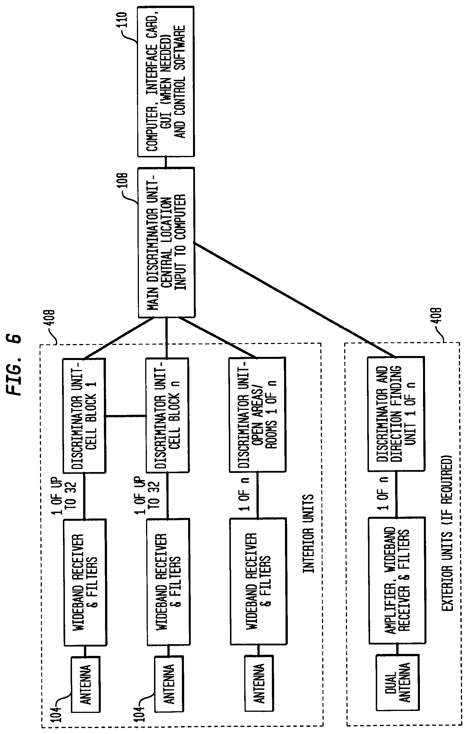
In an embodiment, detector units 408 may be installed in open areas such as gymnasiums, kitchens, cafeterias, craft and work areas and other open areas where a cell phone may be used. The difference in these locations from the cell blocks 402 may include the method of detection and tracking. Since most facilities may only require the identification of a cell phones presence within a room, and there could be many inmates within that room, the process may be to lock-down the room, or rooms, in that area and use a hand held device and a physical search to pinpoint the phone location. A generalized block diagram is shown in FIG. 6. For those facilities that require resolving the location within a large interior room or area, the use of triangulation to resolve to a 10.times.10 foot area may be used.
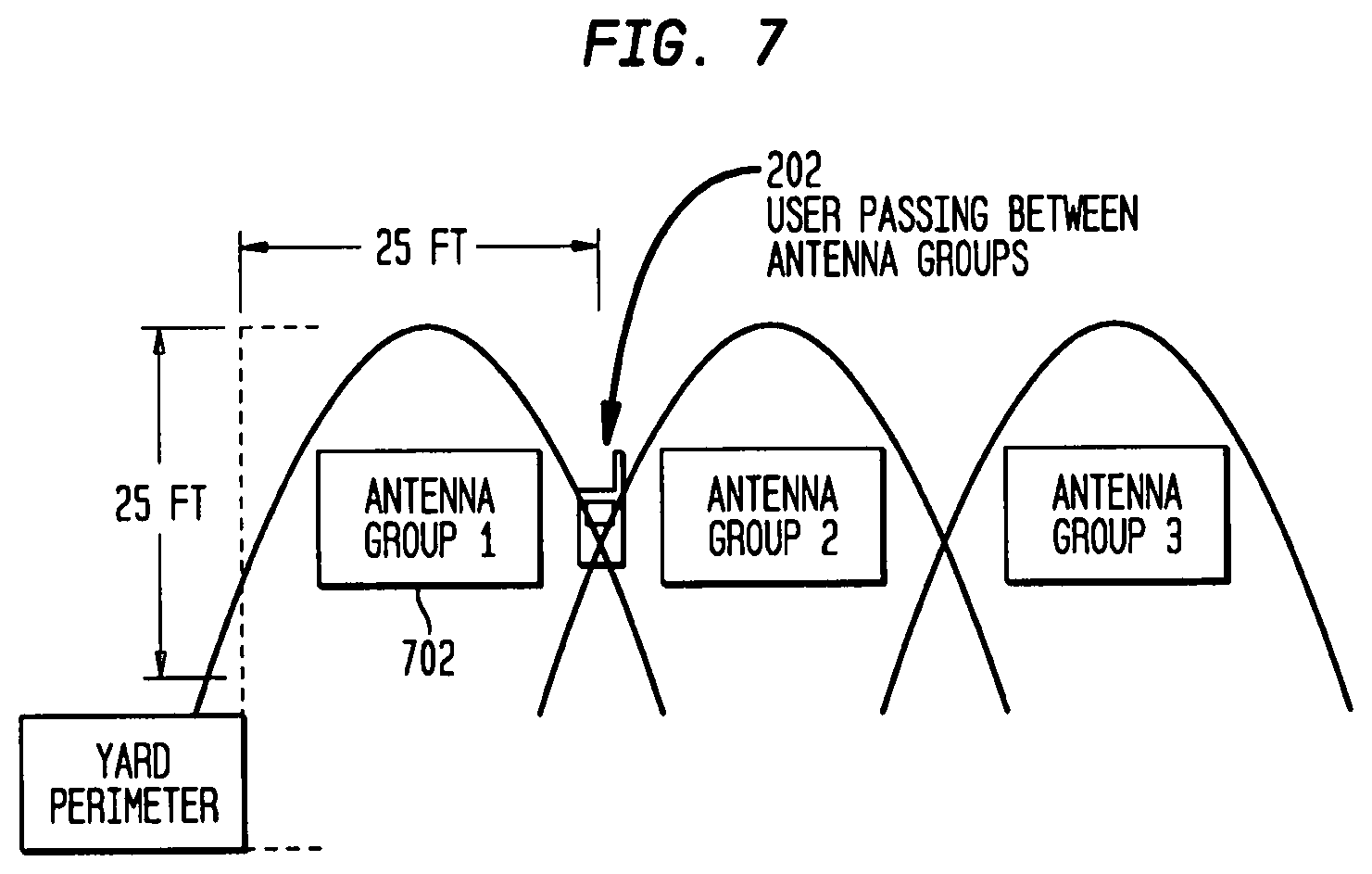
In an embodiment, facilities with the requirement to detect cell phones 202 in outside yard areas, the use of triangulation to a 25.times.25 foot space or smaller foot space may be constructed. As a phone 202 is moved from area coverage 702 to area coverage 702, the system may track its movement. Each square foot sector may overlap an adjoining sector. In this way, as shown in FIG. 7, tracking may be continuous, without any gaps.
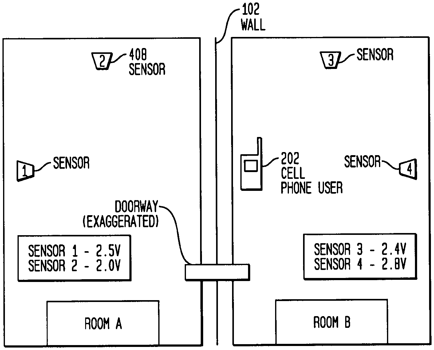
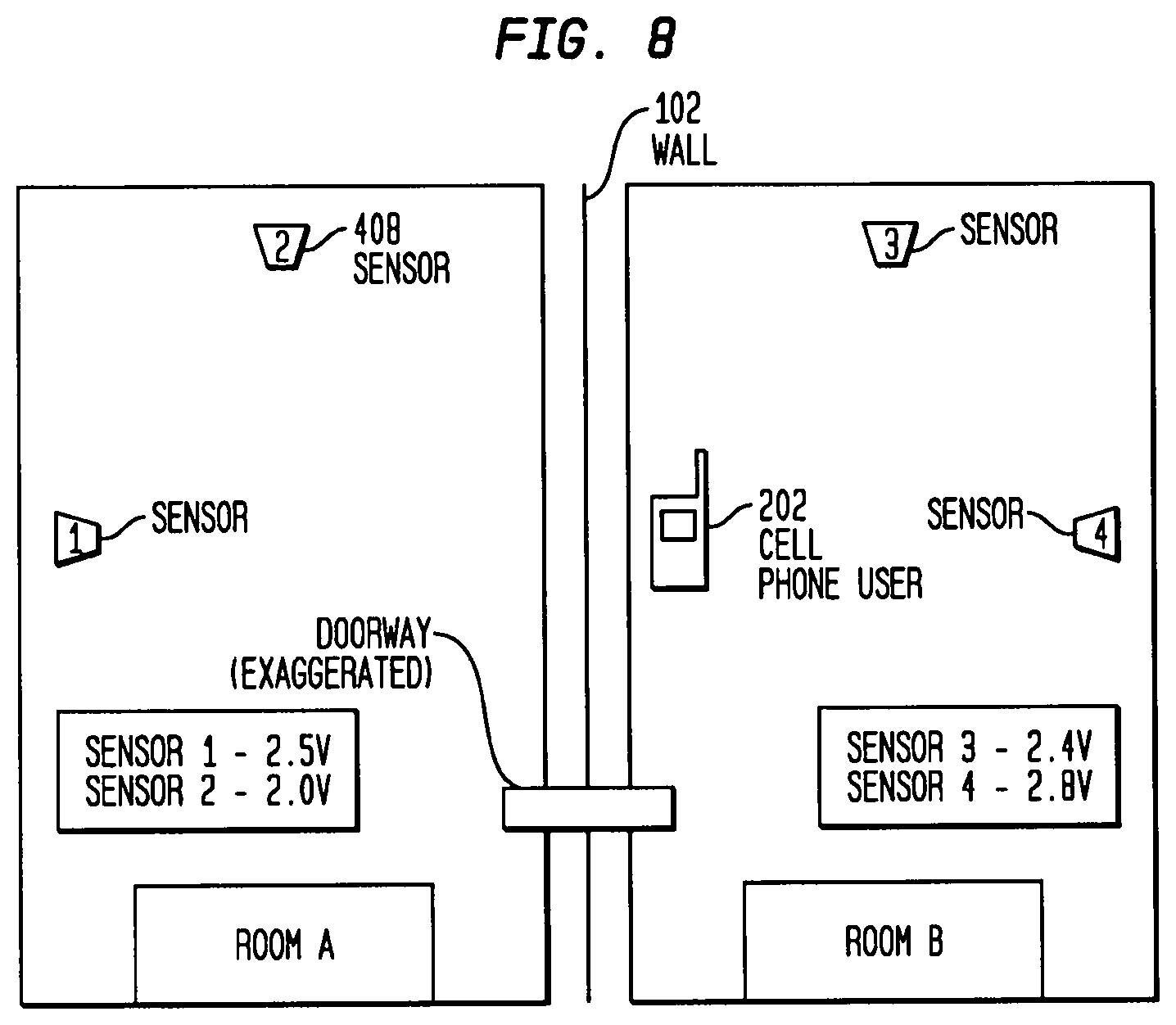
In an embodiment, it may also important to know whether a phone is located on one side of an obstruction 102 or the other, such as doors, walls, and the like. If the wrong room is identified, it may make it more difficult to locate a phone and its user. As shown in FIG. 8, detection of the correct room may depend upon the level of the signal received. Proper placement of the detector units 408 may insure that the phone may be identified in the correct location.
In an embodiment, when sectoring a large room such as a gymnasium, the number and placement of antennas 104 may be critical. In order to sector large regions, such as a ten-by-ten ft section, within the room, the antenna 104 may need to be capable of narrowing their window to an area small enough to meet the requirement. In FIG. 9, there is an omni-directional antenna 104, which detects signal presence. Once a signal crosses a threshold, the direction finding antennas 104 may be turned on to determine the position of the signal. This may be reported to the display 112 and tracked until it is either turned off or moves to another room or hallway. Then, normal positional tracking may take place.
In an embodiment, the transmission detection, identification, and reporting system 100 may work in conjunction with a personal alarm system. This dual role system may allow for more cost effective use of the detection units 408 and provide for greater protection for the correctional officer. This detection system may utilize an individualized frequency, with known frequency separation between detection units 408. The detection configuration of the detection units 408 may provide complete coverage of the facility. Each unit may be continually tracked throughout the facility. At all ingress or egress points the focus of the detection may ensure accurate location of all correctional personnel. With the combined systems more detection units 408 may be need to ensure full coverage.
In an embodiment, the transmission detection, identification, and reporting system 100 may allow for cell phone owner discrimination. The system may provide for the allowance of authorized cell phones within the prohibited area. The system may detect and identify each cell phone and compare the cell phone identity to the allowed cell phone user list. The system may record all phone use and may automatically alert the facility of all prohibited cell phone use. In addition, each cell phone detection event may be identified with a unique identifier and time code, to ensure proper identification.
The cell scan-1 detection system 1000, shown in FIG. 10, is an embodiment of a system for detecting signals of a transmission facility. Antenna 104 receives transmission signals from wireless transmission device (not shown). Antenna 104 may operate, for example in the range of 2.4 GHz with a bandwidth of 465 MHz. The received signals are then provided to a microprocessor to determine if the transmission facility for example is a person with a transmission facility (wristband) and may allow or prevent them from accessing an area, it may also alert the central unit of their entering or desire to enter a restricted area. In an another embodiment, if the transmission facility for example were a cell phone and the cell phone was in use within a restricted area, the cell phone would be identified by the central unit as being in a restricted area, then the system will determine whether the cell phone authorized or not authorized, then the system would make a determination, based upon set rules whether to allow or disallow the transmission unit.
The cell scan-2 detection system 1100, shown in FIG. 11, shows an alternate embodiment of a system for detecting a signal of a transmission facility. For this embodiment, the RF filters (i.e., band pass filter) isolate sets of frequencies for greater sensitivity, in this example a low band cell phone signals and high band cell phone signals. The operation of the elements in FIG. 11 is similar to that of FIG. 10 and need not be discussed in detail herein.
The main board system 1200, shown in FIG. 12, is an embodiment of a main circuit board within a system for detecting transmission facilities. The system may be used to determine each signal received is an actual cell phone signal and not a spurious output, a test may need to be performed that checks for the `persistence` of the received signal. A persistence test may run a timer 1202 for a minimum required time that may be nearly as long as the time of the shortest signal type expected. If the signal is present at the end of the timeout period, it is less likely to be a spurious response and more likely that it is a cell phone output. For example, if a GSM signal of 500 microseconds long is the shortest duration signal of all the cell phone protocols received, the persistence test may run for 450 microseconds to further ensure that the received signal is not merely a spurious response.
The sub-station system 1300, shown in FIG. 13, is an embodiment of a sub-station in a system for detecting transmission facilities.
FIG. 14 illustrates an embodiment of a null detector (1400), wherein the VCO in FIG. 14 tunes to known antenna frequencies and the system detects a null in the known antenna frequencies in which the antenna is detected. In embodiments, the null detection system may detect the presence of a transmission facility even when the transmission facility is not transmitting a signal. In embodiments, a hand held or mounted null detection device may be used in a correctional institution or other government facility. In embodiments, null detection may utilize a transmission-detection source, independent of the transmission source being detected, which is capable of sweeping across the frequency spectrum of interest and receiving it's returning signal. The transmission source sweeps the spectrum of interest, searching for distortions in the returned field. Distortions in the spectrum may be due to the presence of an antenna of a transmission facility 202.
In embodiments of the system described herein, detection levels may be determined by which output levels are possible with the various cell phone technologies that are in use today. Since the system described is an amplitude system, the strongest and weakest possible signals must be determined in order to identify the system's required dynamic range. Cell phone signals vary from -22 dBW to 6 DBW and this range defines the detection requirements of the system. This translates to a maximum signal of 4.0 Watts at the antenna. The minimum value is equal to 0.006 Watts or 6 milliwatts. Therefore, the dynamic range required is -52 dBm to +36 dBm. In order to achieve such a dynamic range, an amplifier that is gain adjustable is required such that an input value of +36 dBm, the amplifier is not saturated.
In the embodiment, the system determines the characteristics required to insure that each cell phone is correctly identified. The amplitude of each signal is determined which allows the system to determine which sensor has received the largest signal. The system time stamps each data sample so that other sensors receiving the same signal will be recognized as such when the data is presented for analysis. Each sensor analyzes the wave shape of the signal detected. Each transmission type (i.e., CDMA2000, PCS, TDMA, GSM, IS-95, etc.) has a unique wave shape. These wave shapes allow the analysis software to recognize that signals seen in different parts of a facility can be associated with each other (using time and wave shape) and the signal that consistently contains the largest amplitude will be identified as closest to the cell phone transmission
In embodiments of the invention, signals directed toward an IED (improvised explosive device) may be intercepted, identified and denied service. Such interception may be up to a known range in forward and side quadrants. The identification and determination of the position of the person or persons using a satellite phone and/or land-based cell phone may be determined. Cell phones, as well as other RF devices, e.g., garage door openers, walkie-talkie, etc., may be captured, identified and/or jammed that are attempting to activate or contact the IED.
In embodiments of the invention, when a cell phone, for example, is on, but not in an active communication, the cell phone is essentially invisible to anyone attempting to monitor cell phone activity. In order to be aware of the existence of such "on but not transmitting devices" the system described herein operates as a cell tower. That is, the system actively addresses the problem of cell phone detection by operating (becoming) the tower. A vehicle with similar (but modified equipment to that of a cell tower may actively poll the area of phones that are "on but not in a communication of any sort." The vehicle (i.e., Pseudo Tower) collects the current database of active phones and those phones in standby from the tower(s) in the area and uses this data base to poll these phones in order to locate them. Once potential phones that could be possible detonation cell phones are identified and located, the Pseudo Tower would affect a handoff and make itself the active tower. Thus, the captured cell phones are not allowed to rotate back to (i.e, connect to) the local cell phone tower, insuring that any calls attempting to communicate with the detonation cell phone will not be sent. As one of the goals is to identify the person who is attempting to contact the detonation cell phone, a call history of each suspect cell phone may be analyzed.
When a caller attempts to activate an IED, the caller's presence can be identified. Furthermore, the call being made is not forwarded to the detonation cell phone and the IED will not be activated. By determining a peak angle (triangulation) the caller's cell phone/satellite phone signal, the direction of the caller is then known. Direction identification is performed by using a technique such an interferometry. In this case, multiple antennas employing interferometry may be used to scan through the current cell phone traffic identifying first, candidate threats and then, pinpointing high probability locations which can be viewed through a high powered binoculars to determine whether the candidate is in need of investigation. Criteria for determining which cell locations may be threats is a pole or road sign, etc. The Psuedo Tower may continue controlling all of the phones in the area, preventing any forwarding of calls until all possible threats have been cleared. At this point, the personnel have the option of going after the caller or deactivating the IED, or both. It would be possible to clear the area and detonate the device later if that is a desired plan of action.
Given the varying parameters by which detonation can take place, the Pseudo Tower may also be designed to deny service to any active and inactive phone within a given geographical area and pinpoint the location of said phones.
Satellite cell phone transmission presents a somewhat different problem. Since the transmission from phone to satellite to phone is communicated to a number of satellites, becoming a replacement for the satellite will require cooperation from the provider. Via one or more specific codes, the satellites may be told that the vehicle mounted satellite simulator (i.e., Pseudo Tower) will be taking over the control of phones within a certain radius. Since this is a moving or ever changing circle, the replacement "satellite" will have to continuously update the actual satellite of its position and which phones are being released and which phones are being controlled. Once this function has been implemented, the control of the suspect phones is similar to that of the cell phone. Determining the caller's position and the location of the detonation phone is as above.
FIG. 15 illustrates a system 1500 for implementing the principles of the invention shown herein. In this exemplary system embodiment 1500, input data is received from sources 1505 over network 1550 and is processed in accordance with one or more programs, either software or firmware, executed by processing system 1510. The results of processing system 1510 may then be transmitted over network 1570 for viewing on display 1580, reporting device 1590 and/or a second processing system 1595.
Processing system 1510 includes one or more input/output devices 1540 that receive data from the illustrated sources or devices 1505 over network 1550. The received data is then applied to processor 1520, which is in communication with input/output device 1540 and memory 1530. Input/output devices 1540, processor 1520 and memory 1530 may communicate over a communication medium 1525. Communication medium 1525 may represent a communication network, e.g., ISA, PCI, PCMCIA bus, one or more internal connections of a circuit, circuit card or other device, as well as portions and combinations of these and other communication media.
Processing system 1510 and/or processor 1520 may be representative of a handheld calculator, special purpose or general purpose processing system, desktop computer, laptop computer, palm computer, or personal digital assistant (PDA) device, etc., as well as portions or combinations of these and other devices that can perform the operations illustrated.
Processor 1520 may be a central processing unit (CPU) or dedicated hardware/software, such as a PAL, ASIC, FGPA, operable to execute computer instruction code or a combination of code and logical operations. In one embodiment, processor 1520 may include code which, when executed by the processor, performs the operations illustrated herein. The code may be contained in memory 1530, may be read or downloaded from a memory medium such as a CD-ROM or floppy disk, represented as 1583, may be provided by a manual input device 1585, such as a keyboard or a keypad entry, or may be read from a magnetic or optical medium (not shown) or via a second I/O device 1587 when needed. Information items provided by devices 1583, 1585, 1587 may be accessible to processor 1520 through input/output device 1540, as shown. Further, the data received by input/output device 1540 may be immediately accessible by processor 1520 or may be stored in memory 1530. Processor 1520 may further provide the results of the processing to display 1580, recording device 1590 or a second processing unit 795.
As one skilled in the art would recognize, the terms processor, processing system, computer or computer system may represent one or more processing units in communication with one or more memory units and other devices, e.g., peripherals, connected electronically to and communicating with the at least one processing unit. Furthermore, the devices illustrated may be electronically connected to the one or more processing units via internal busses, e.g., serial, parallel, ISA bus, Micro Channel bus, PCI bus, PCMCIA bus, USB, etc., or one or more internal connections of a circuit, circuit card or other device, as well as portions and combinations of these and other communication media, or an external network, e.g., the Internet and Intranet. In other embodiments, hardware circuitry may be used in place of, or in combination with, software instructions to implement the invention. For example, the elements illustrated herein may also be implemented as discrete hardware elements or may be integrated into a single unit.
As would be understood, the operations illustrated may be performed sequentially or in parallel using different processors to determine specific values. Processing system 1510 may also be in two-way communication with each of the sources 1505. Processing system 1510 may further receive or transmit data over one or more network connections from a server or servers over, e.g., a global computer communications network such as the Internet, Intranet, a wide area network (WAN), a metropolitan area network (MAN), a local area network (LAN), a terrestrial broadcast system, a cable network, a satellite network, a wireless network, or a telephone network (POTS), as well as portions or combinations of these and other types of networks. As will be appreciated, networks 1550 and 1570 may also be internal networks or one or more internal connections of a circuit, circuit card or other device, as well as portions and combinations of these and other communication media or an external network, e.g., the Internet and Intranet.
FIG. 16 illustrates a conventional mobile or wireless device, that blends computing and communications technologies that provide a wide range of consumer and business0related functions. The complexity of conventional mobile devices (e.g., smart phones) caries over to the RF analog/mixed signal world of multi-radio transmissions.
As shown, a conventional mobile device may include a single or multiple antenna 1610, 1615, which detect signals in one or more frequency bands. The antenna 1610, 1620 may be broadband omni-directional antenna (conventional cellular phone technology) or narrow band omni/directional antenna (WIFI technology).
Signals detected by antenna 1610, 1620 may be provided to a switch 1620 which provides the signals to one or more filter bands 1630a . . . 1630n sequentially in order to pass detected signal onto a receiving system 1640 for processing. For example, conventional mobile devices for cellular carriers such as AT&T, may receive in one or more frequency bands (e.g., 700 MHz, 850 MHz, 1900 MHz and 2300 MHz).
Filters 1630a-1630n thus allow a single mobile device to operate in any of the frequency bands that AT&T, for example, may operate in. Similarly the other conventional cellular carriers (Verizon, T-Mobile and Sprint) operate multiple frequency bands.
After determining the appropriate frequency band (and frequency) for receiving or transmitting a signal, the receiver 1640 processes the data for the processor 1650. Processor 1650 then decodes the data and provides the received data to a D/A converter 1660 that outputs the received signal through a speaker 1670.
Similarly, a user may use a microphone 1680 to input voice data to A/D converter 1660 which converts the analog speech data to digital data. The digital data is provided to the processor 1650 for subsequent processing by the receiver (i.e., transceiver) 1640 and output through antenna 1610 and/or 1620.
While the operation of the mobile device in FIG. 16 is disclosed with regard to receiving or transmitting a signal on a single antenna (e.g., 161), it would be recognized that current mobile devices may use multiple frequency/antenna transmission/reception in order to improve the reception and/or transmission of a signal. Such multiple frequency/antenna operation is referred to a MIMO (multiple input/multiple output).
FIG. 17 illustrates an exemplary processing in accordance with the principles of the invention.
As illustrated in FIG. 17, a system outputs a plurality of frequencies within a selected band (referred to as "I") at step 1710. At step 1720, returns from the plurality of transmitted frequencies are detected and stored. At step 1730 a null pattern or patterns in the detected returns is formulated. The null pattern represents those frequencies that have been absorbed by a receiving antenna. At step 1740 a determination is made whether all bands have been processed. If not a next band is selected, at step 1750, and processing continues at step 1710 to output a plurality of frequencies in the next selected band.
However, if all bands have been processed, then a correlation of the detected null patterns is performed at step 1760. As each cell phone associated with conventional wireless carrier (e.g., AT&T) has a unique set of operating frequency bands, a null pattern in one or more frequency bands may be used to identify a mobile device associated with a specific carrier at step 1770.
As would be recognized, the outputting to the frequencies within a band may be performed in a discreet manner, in a sweeping manner, or a randomly selected manner. Similarly, while it has been shown that each frequency band is individually selected, it would be recognized that the frequency outputs may be in multiple bands concurrently.
While there has been shown, described, and pointed out fundamental novel features of the present invention as applied to preferred embodiments thereof, it will be understood that various omissions and substitutions and changes in the apparatus described, in the form and details of the devices disclosed, and in their operation, may be made by those skilled in the art without departing from the spirit of the present invention. For example, while the device described herein is referred to as a transmitting device, it would be recognized by those skilled in the art that the device may incorporate a receiving unit, designed to operate in one or more frequency bands over a wide frequency range. For example, the receiving system may represent a crystal receiving system that may detect one or more signals within a frequency range, or may represent a superhetrodyne receiver that may detect and determine the frequency of operation of received signals.
* * * * *
D00000
D00001
D00002
D00003
D00004
D00005
D00006
D00007
D00008
D00009
D00010
D00011
D00012
D00013
D00014
D00015
D00016
D00017
XML
uspto.report is an independent third-party trademark research tool that is not affiliated, endorsed, or sponsored by the United States Patent and Trademark Office (USPTO) or any other governmental organization. The information provided by uspto.report is based on publicly available data at the time of writing and is intended for informational purposes only.
While we strive to provide accurate and up-to-date information, we do not guarantee the accuracy, completeness, reliability, or suitability of the information displayed on this site. The use of this site is at your own risk. Any reliance you place on such information is therefore strictly at your own risk.
All official trademark data, including owner information, should be verified by visiting the official USPTO website at www.uspto.gov. This site is not intended to replace professional legal advice and should not be used as a substitute for consulting with a legal professional who is knowledgeable about trademark law.