Automatic transmissions and methods therefor
Vasiliotis , et al.
U.S. patent number 10,704,687 [Application Number 15/680,506] was granted by the patent office on 2020-07-07 for automatic transmissions and methods therefor. This patent grant is currently assigned to Fallbrook Intellectual Property Company LLC. The grantee listed for this patent is Fallbrook Intellectual Property Company LLC. Invention is credited to Loren T. McDaniel, Christopher M. Vasiliotis.


| United States Patent | 10,704,687 |
| Vasiliotis , et al. | July 7, 2020 |
Automatic transmissions and methods therefor
Abstract
Systems and methods for controlling transmissions and associated vehicles, machines, equipment, etc., are disclosed. In one case, a transmission control system includes a control unit configured to use a sensed vehicle speed and a commanded, target constant input speed to maintain an input speed substantially constant. The system includes one or more maps that associate a speed ratio of a transmission with a vehicle speed. In one embodiment, one such map associates an encoder position with a vehicle speed. Regarding a specific application, an automatic bicycle transmission shifting system is contemplated. An exemplary automatic bicycle includes a control unit, a shift actuator, various sensors, and a user interface. The control unit is configured to cooperate with a logic module and an actuator controller to control the cadence of a rider. In one embodiment, a memory of, or in communication with, the control unit includes one or more constant cadence maps that associate transmission speed ratios with bicycle speeds.
| Inventors: | Vasiliotis; Christopher M. (Denver, CO), McDaniel; Loren T. (Austin, TX) | ||||||||||
|---|---|---|---|---|---|---|---|---|---|---|---|
| Applicant: |
|
||||||||||
| Assignee: | Fallbrook Intellectual Property
Company LLC (Cedar Park, TX) |
||||||||||
| Family ID: | 40467044 | ||||||||||
| Appl. No.: | 15/680,506 | ||||||||||
| Filed: | August 18, 2017 |
Prior Publication Data
| Document Identifier | Publication Date | |
|---|---|---|
| US 20170343105 A1 | Nov 30, 2017 | |
Related U.S. Patent Documents
| Application Number | Filing Date | Patent Number | Issue Date | ||
|---|---|---|---|---|---|
| 15012420 | Feb 1, 2016 | 9739375 | |||
| 14147026 | Feb 2, 2016 | 9249880 | |||
| 13681792 | Jan 7, 2014 | 8626409 | |||
| 12335810 | Nov 27, 2012 | 8321097 | |||
| 61016305 | Dec 21, 2007 | ||||
| Current U.S. Class: | 1/1 |
| Current CPC Class: | B62M 25/08 (20130101); F16H 61/6645 (20130101); F16H 61/6646 (20130101); F16H 61/66 (20130101); B62M 6/40 (20130101); B62M 11/16 (20130101); F16H 15/52 (20130101); B62M 11/14 (20130101) |
| Current International Class: | B62M 11/16 (20060101); B62M 6/40 (20100101); F16H 61/664 (20060101); B62M 11/14 (20060101); F16H 15/52 (20060101); F16H 61/66 (20060101); B62M 25/08 (20060101) |
References Cited [Referenced By]
U.S. Patent Documents
| 4963 | February 1847 | Armstrong et al. |
| 719595 | February 1903 | Huss |
| 1121210 | December 1914 | Techel |
| 1175677 | March 1916 | Barnes |
| 1207985 | December 1916 | Null et al. |
| 1380006 | May 1921 | Nielsen |
| 1390971 | September 1921 | Samain |
| 1558222 | October 1925 | Beetow |
| 1629902 | May 1927 | Arter et al. |
| 1631069 | May 1927 | Smith |
| 1686446 | October 1928 | Gilman |
| 1774254 | August 1930 | Daukus |
| 1793571 | February 1931 | Vaughn |
| 1847027 | February 1932 | Thomsen et al. |
| 1850189 | March 1932 | Weiss |
| 1858696 | May 1932 | Weiss |
| 1865102 | June 1932 | Hayes |
| 1978439 | October 1934 | Sharpe |
| 2030203 | February 1936 | Gove et al. |
| 2060884 | November 1936 | Madle |
| 2086491 | July 1937 | Dodge |
| 2100629 | November 1937 | Chilton |
| 2109845 | March 1938 | Madle |
| 2112763 | March 1938 | Cloudsley |
| 2131158 | September 1938 | Almen et al. |
| 2134225 | October 1938 | Christiansen |
| 2152796 | April 1939 | Erban |
| 2196064 | April 1940 | Erban |
| 2209254 | July 1940 | Ahnger |
| 2230398 | February 1941 | Benjafield |
| 2259933 | October 1941 | Holloway |
| 2269434 | January 1942 | Brooks |
| 2325502 | July 1943 | Auguste |
| RE22761 | May 1946 | Wemp |
| 2461258 | February 1949 | Brooks |
| 2469653 | May 1949 | Kopp |
| 2480968 | September 1949 | Ronai |
| 2553465 | May 1951 | Monge |
| 2586725 | February 1952 | Henry |
| 2595367 | May 1952 | Picanol |
| 2596538 | May 1952 | Dicke |
| 2597849 | May 1952 | Alfredeen |
| 2675713 | April 1954 | Acker |
| 2696888 | December 1954 | Chillson et al. |
| 2868038 | May 1955 | Billeter |
| 2716357 | August 1955 | Rennerfelt |
| 2730904 | January 1956 | Rennerfelt |
| 2748614 | June 1956 | Weisel |
| 2959070 | January 1959 | Flinn |
| 2873911 | February 1959 | Perrine |
| 2874592 | February 1959 | Oehrli |
| 2883883 | April 1959 | Chillson |
| 2891213 | June 1959 | Kern |
| 2901924 | September 1959 | Banker |
| 2913932 | November 1959 | Oehrli |
| 2931234 | April 1960 | Hayward |
| 2931235 | April 1960 | Hayward |
| 2949800 | August 1960 | Neuschotz |
| 2959063 | November 1960 | Perry |
| 2959972 | November 1960 | Madson |
| 2964959 | December 1960 | Beck |
| 3008061 | November 1961 | Mims et al. |
| 3028778 | April 1962 | Hayward |
| 3035460 | May 1962 | Guichard |
| 3048056 | August 1962 | Wolfram |
| 3051020 | August 1962 | Hartupee |
| 3071194 | January 1963 | Geske |
| 3086704 | April 1963 | Hurtt |
| 3087348 | April 1963 | Kraus |
| 3154957 | November 1964 | Kashihara |
| 3163050 | December 1964 | Kraus |
| 3176542 | April 1965 | Monch |
| 3184983 | May 1965 | Kraus |
| 3204476 | September 1965 | Rouverol |
| 3209606 | October 1965 | Yamamoto |
| 3211364 | October 1965 | Wentling et al. |
| 3216283 | November 1965 | General |
| 3229538 | January 1966 | Schlottler |
| 3237468 | March 1966 | Schlottler |
| 3246531 | April 1966 | Kashihara |
| 3248960 | May 1966 | Schottler |
| 3273468 | September 1966 | Allen |
| 3280646 | October 1966 | Lemieux |
| 3283614 | November 1966 | Hewko |
| 3292443 | December 1966 | Felix |
| 3340895 | September 1967 | Osgood, Jr. et al. |
| 3374009 | March 1968 | Jeunet |
| 3407687 | October 1968 | Hayashi |
| 3430504 | March 1969 | Dickenbrock |
| 3439563 | April 1969 | Petty |
| 3440895 | April 1969 | Fellows |
| 3464281 | September 1969 | Hiroshi et al. |
| 3477315 | November 1969 | Macks |
| 3487726 | January 1970 | Burnett |
| 3487727 | January 1970 | Gustafsson |
| 3574289 | April 1971 | Scheiter et al. |
| 3581587 | June 1971 | Dickenbrock |
| 3661404 | May 1972 | Bossaer |
| 3695120 | October 1972 | Titt |
| 3707888 | January 1973 | Schottler |
| 3727473 | April 1973 | Bayer |
| 3727474 | April 1973 | Fullerton |
| 3736803 | June 1973 | Horowitz et al. |
| 3768715 | October 1973 | Tout |
| 3769849 | November 1973 | Hagen |
| 3800607 | April 1974 | Zurcher |
| 3802284 | April 1974 | Sharpe et al. |
| 3810398 | May 1974 | Kraus |
| 3820416 | June 1974 | Kraus |
| 3866985 | February 1975 | Whitehurst |
| 3891235 | June 1975 | Shelly |
| 3934493 | January 1976 | Hillyer |
| 3954282 | May 1976 | Hege |
| 3984129 | October 1976 | Hege |
| 3987681 | October 1976 | Keithley et al. |
| 3996807 | December 1976 | Adams |
| 4023442 | May 1977 | Woods et al. |
| 4053173 | October 1977 | Chase, Sr. |
| 4086026 | April 1978 | Tamanini |
| 4098146 | July 1978 | McLarty |
| 4103514 | August 1978 | Grosse-Entrup |
| 4159653 | July 1979 | Koivunen |
| 4169609 | October 1979 | Zampedro |
| 4177683 | December 1979 | Moses |
| 4227712 | October 1980 | Dick |
| 4314485 | February 1982 | Adams |
| 4345486 | August 1982 | Olesen |
| 4369667 | January 1983 | Kemper |
| 4391156 | July 1983 | Tibbals |
| 4459873 | July 1984 | Black |
| 4464952 | August 1984 | Stubbs |
| 4468984 | September 1984 | Castelli et al. |
| 4493677 | January 1985 | Ikenoya |
| 4494524 | January 1985 | Wagner |
| 4496051 | January 1985 | Ortner |
| 4501172 | February 1985 | Kraus |
| 4515040 | May 1985 | Takeuchi et al. |
| 4526255 | July 1985 | Hennessey et al. |
| 4546673 | October 1985 | Shigematsu et al. |
| 4549874 | October 1985 | Wen |
| 4560369 | December 1985 | Hattori |
| 4567781 | February 1986 | Russ |
| 4569670 | February 1986 | McIntosh |
| 4574649 | March 1986 | Seol |
| 4585429 | April 1986 | Marier |
| 4617838 | October 1986 | Anderson |
| 4628766 | December 1986 | De Brie Perry |
| 4630839 | December 1986 | Seol |
| 4631469 | December 1986 | Tsuboi et al. |
| 4647060 | March 1987 | Tomkinson |
| 4651082 | March 1987 | Kaneyuki |
| 4663990 | May 1987 | Itoh et al. |
| 4700581 | October 1987 | Tibbals, Jr. |
| 4713976 | December 1987 | Wilkes |
| 4717368 | January 1988 | Yamaguchi et al. |
| 4725258 | February 1988 | Joanis, Jr. |
| 4735430 | April 1988 | Tomkinson |
| 4738164 | April 1988 | Kaneyuki |
| 4744261 | May 1988 | Jacobson |
| 4756211 | July 1988 | Fellows |
| 4781663 | November 1988 | Reswick |
| 4806066 | February 1989 | Rhodes et al. |
| 4838122 | June 1989 | Takamiya et al. |
| 4856374 | August 1989 | Kreuzer |
| 4857035 | August 1989 | Anderson |
| 4869130 | September 1989 | Wiecko |
| 4881925 | November 1989 | Hattori |
| 4900046 | February 1990 | Aranceta-Angoitia |
| 4909101 | March 1990 | Terry |
| 4918344 | April 1990 | Chikamori et al. |
| 4961477 | October 1990 | Sweeney |
| 4964312 | October 1990 | Kraus |
| 4976170 | December 1990 | Hayashi et al. |
| 5006093 | April 1991 | Itoh et al. |
| 5020384 | June 1991 | Kraus |
| 5025685 | June 1991 | Kobayashi et al. |
| 5033322 | July 1991 | Nakano |
| 5033571 | July 1991 | Morimoto |
| 5037361 | August 1991 | Takahashi |
| 5044214 | September 1991 | Barber |
| 5059158 | October 1991 | Bellio et al. |
| 5069655 | December 1991 | Schivelbusch |
| 5083982 | January 1992 | Sato |
| 5099710 | March 1992 | Nakano |
| 5121654 | June 1992 | Fasce |
| 5125677 | June 1992 | Ogilvie et al. |
| 5138894 | August 1992 | Kraus |
| 5156412 | October 1992 | Meguerditchian |
| 5194052 | March 1993 | Ueda et al. |
| 5230258 | July 1993 | Nakano |
| 5236211 | August 1993 | Meguerditchian |
| 5236403 | August 1993 | Schievelbusch |
| 5254044 | October 1993 | Anderson |
| 5261858 | November 1993 | Browning |
| 5267920 | December 1993 | Hibi |
| 5273501 | December 1993 | Schievelbusch |
| 5318486 | June 1994 | Lutz |
| 5319486 | June 1994 | Vogel et al. |
| 5323570 | June 1994 | Kuhlman et al. |
| 5330396 | July 1994 | Lohr et al. |
| 5355749 | October 1994 | Obara et al. |
| 5356348 | October 1994 | Bellio et al. |
| 5375865 | December 1994 | Terry, Sr. |
| 5379661 | January 1995 | Nakano |
| 5383677 | January 1995 | Thomas |
| 5387000 | February 1995 | Sato |
| 5401221 | March 1995 | Fellows et al. |
| 5413540 | May 1995 | Streib et al. |
| 5451070 | September 1995 | Lindsay et al. |
| 5489003 | February 1996 | Ohyama et al. |
| 5508574 | April 1996 | Vlock |
| 5562564 | October 1996 | Folino |
| 5564998 | October 1996 | Fellows |
| 5601301 | February 1997 | Liu |
| 5607373 | March 1997 | Ochiai et al. |
| 5645507 | July 1997 | Hathaway |
| 5651750 | July 1997 | Imanishi et al. |
| 5664636 | September 1997 | Ikuma et al. |
| 5669758 | September 1997 | Williamson |
| 5669845 | September 1997 | Muramoto et al. |
| 5683322 | November 1997 | Meyerle |
| 5690346 | November 1997 | Keskitalo |
| 5701786 | December 1997 | Kawakami |
| 5722502 | March 1998 | Kubo |
| 5746676 | May 1998 | Kawase et al. |
| 5755303 | May 1998 | Yamamoto et al. |
| 5799541 | September 1998 | Arbeiter |
| 5819864 | October 1998 | Koike et al. |
| 5823052 | October 1998 | Nobumoto |
| 5846155 | December 1998 | Taniguchi et al. |
| 5888160 | March 1999 | Miyata et al. |
| 5895337 | April 1999 | Fellows et al. |
| 5899827 | May 1999 | Nakano et al. |
| 5902207 | May 1999 | Sugihara |
| 5967933 | October 1999 | Valdenaire |
| 5976054 | November 1999 | Yasuoka |
| 5984826 | November 1999 | Nakano |
| 5995895 | November 1999 | Watt et al. |
| 6000707 | December 1999 | Miller |
| 6003649 | December 1999 | Fischer |
| 6004239 | December 1999 | Makino |
| 6006151 | December 1999 | Graf |
| 6012538 | January 2000 | Sonobe et al. |
| 6015359 | January 2000 | Kunii |
| 6019701 | February 2000 | Mori et al. |
| 6029990 | February 2000 | Busby |
| 6042132 | March 2000 | Suenaga et al. |
| 6045477 | April 2000 | Schmidt |
| 6045481 | April 2000 | Kumagai |
| 6050854 | April 2000 | Fang et al. |
| 6053833 | April 2000 | Masaki |
| 6053841 | April 2000 | Kolde et al. |
| 6054844 | April 2000 | Frank |
| 6066067 | May 2000 | Greenwood |
| 6071210 | June 2000 | Kato |
| 6074320 | June 2000 | Miyata et al. |
| 6076846 | June 2000 | Clardy |
| 6079726 | June 2000 | Busby |
| 6083139 | July 2000 | Deguchi |
| 6086506 | July 2000 | Petersmann et al. |
| 6095940 | August 2000 | Ai et al. |
| 6099431 | August 2000 | Hoge et al. |
| 6101895 | August 2000 | Yamane |
| 6113513 | September 2000 | Itoh et al. |
| 6119539 | September 2000 | Papanicolaou |
| 6119800 | September 2000 | McComber |
| 6155132 | December 2000 | Yamane |
| 6159126 | December 2000 | Oshidari |
| 6171210 | January 2001 | Miyata et al. |
| 6174260 | January 2001 | Tsukada et al. |
| 6186922 | February 2001 | Bursal et al. |
| 6201315 | March 2001 | Larsson |
| 6210297 | April 2001 | Knight |
| 6217473 | April 2001 | Ueda et al. |
| 6217478 | April 2001 | Vohmann et al. |
| 6241636 | June 2001 | Miller |
| 6243638 | June 2001 | Abo et al. |
| 6251038 | June 2001 | Ishikawa et al. |
| 6258003 | July 2001 | Hirano et al. |
| 6261200 | July 2001 | Miyata et al. |
| 6293575 | September 2001 | Burrows et al. |
| 6296593 | October 2001 | Gotou |
| 6311113 | October 2001 | Danz et al. |
| 6312358 | November 2001 | Goi et al. |
| 6322475 | November 2001 | Miller |
| 6325386 | December 2001 | Shoge |
| 6340067 | January 2002 | Fujiwara |
| 6358174 | March 2002 | Folsom et al. |
| 6358178 | March 2002 | Wittkopp |
| 6367833 | April 2002 | Horiuchi |
| 6371878 | April 2002 | Bowen |
| 6375412 | April 2002 | Dial |
| 6390945 | May 2002 | Young |
| 6390946 | May 2002 | Hibi et al. |
| 6406399 | June 2002 | Ai |
| 6414401 | July 2002 | Kuroda et al. |
| 6419608 | July 2002 | Miller |
| 6425838 | July 2002 | Matsubara et al. |
| 6434960 | August 2002 | Rousseau |
| 6440035 | August 2002 | Tsukada et al. |
| 6440037 | August 2002 | Takagi et al. |
| 6459978 | October 2002 | Tamiguchi et al. |
| 6461268 | October 2002 | Milner |
| 6482094 | November 2002 | Kefes |
| 6492785 | December 2002 | Kasten et al. |
| 6494805 | December 2002 | Ooyama et al. |
| 6499373 | December 2002 | Van Cor |
| 6514175 | February 2003 | Taniguchi et al. |
| 6523223 | February 2003 | Wang |
| 6532890 | March 2003 | Chen |
| 6551210 | April 2003 | Miller |
| 6558285 | May 2003 | Sieber |
| 6561941 | May 2003 | Nakano et al. |
| 6571726 | June 2003 | Tsai et al. |
| 6575047 | June 2003 | Reik et al. |
| 6658338 | December 2003 | Joe et al. |
| 6659901 | December 2003 | Sakai et al. |
| 6672418 | January 2004 | Makino |
| 6676559 | January 2004 | Miller |
| 6679109 | January 2004 | Gierling et al. |
| 6682432 | January 2004 | Shinozuka |
| 6689012 | February 2004 | Miller |
| 6721637 | April 2004 | Abe et al. |
| 6723014 | April 2004 | Shinso et al. |
| 6723016 | April 2004 | Sumi |
| 6805654 | October 2004 | Nishii |
| 6808053 | October 2004 | Kirkwood et al. |
| 6839617 | January 2005 | Mensler et al. |
| 6849020 | February 2005 | Sumi |
| 6859709 | February 2005 | Joe et al. |
| 6868949 | March 2005 | Braford |
| 6931316 | August 2005 | Joe et al. |
| 6932739 | August 2005 | Miyata et al. |
| 6942593 | September 2005 | Nishii et al. |
| 6945903 | September 2005 | Miller |
| 6949049 | September 2005 | Miller |
| 6958029 | October 2005 | Inoue |
| 6991575 | January 2006 | Inoue |
| 6991579 | January 2006 | Kobayashi et al. |
| 7000496 | February 2006 | Wessel et al. |
| 7011600 | March 2006 | Miller et al. |
| 7011601 | March 2006 | Miller |
| 7014591 | March 2006 | Miller |
| 7029418 | April 2006 | Taketsuna et al. |
| 7032914 | April 2006 | Miller |
| 7036620 | May 2006 | Miller et al. |
| 7044884 | May 2006 | Miller |
| 7063195 | June 2006 | Berhan |
| 7063640 | June 2006 | Miller |
| 7074007 | July 2006 | Miller |
| 7074154 | July 2006 | Miller |
| 7074155 | July 2006 | Miller |
| 7077777 | July 2006 | Miyata et al. |
| 7086979 | August 2006 | Frenken |
| 7086981 | August 2006 | Ali et al. |
| 7094171 | August 2006 | Inoue |
| 7111860 | September 2006 | Grimaldos |
| 7112158 | September 2006 | Miller |
| 7112159 | September 2006 | Miller et al. |
| 7125297 | October 2006 | Miller et al. |
| 7131930 | November 2006 | Miller et al. |
| 7140999 | November 2006 | Miller |
| 7147586 | December 2006 | Miller et al. |
| 7153233 | December 2006 | Miller et al. |
| 7156770 | January 2007 | Miller |
| 7160220 | January 2007 | Shinojima et al. |
| 7160222 | January 2007 | Miller |
| 7163485 | January 2007 | Miller |
| 7163486 | January 2007 | Miller et al. |
| 7166052 | January 2007 | Miller et al. |
| 7166056 | January 2007 | Miller et al. |
| 7166057 | January 2007 | Miller et al. |
| 7166058 | January 2007 | Miller et al. |
| 7169076 | January 2007 | Miller et al. |
| 7172529 | February 2007 | Miller et al. |
| 7175564 | February 2007 | Miller |
| 7175565 | February 2007 | Miller et al. |
| 7175566 | February 2007 | Miller et al. |
| 7192381 | March 2007 | Miller et al. |
| 7197915 | April 2007 | Luh et al. |
| 7198582 | April 2007 | Miller et al. |
| 7198583 | April 2007 | Miller et al. |
| 7198584 | April 2007 | Miller et al. |
| 7198585 | April 2007 | Miller et al. |
| 7201693 | April 2007 | Miller et al. |
| 7201694 | April 2007 | Miller et al. |
| 7201695 | April 2007 | Miller et al. |
| 7204777 | April 2007 | Miller et al. |
| 7207918 | April 2007 | Shimazu |
| 7214159 | May 2007 | Miller et al. |
| 7217215 | May 2007 | Miller et al. |
| 7217216 | May 2007 | Inoue |
| 7217219 | May 2007 | Miller |
| 7217220 | May 2007 | Careau et al. |
| 7232395 | June 2007 | Miller et al. |
| 7234873 | June 2007 | Kato et al. |
| 7235031 | June 2007 | Miller et al. |
| D546741 | July 2007 | Iteya et al. |
| 7238136 | July 2007 | Miller et al. |
| 7238137 | July 2007 | Miller et al. |
| 7238138 | July 2007 | Miller et al. |
| 7238139 | July 2007 | Roethler et al. |
| 7246672 | July 2007 | Shirai et al. |
| 7250018 | July 2007 | Miller et al. |
| D548655 | August 2007 | Barrow et al. |
| 7261663 | August 2007 | Miller et al. |
| 7275610 | October 2007 | Kuang et al. |
| 7285068 | October 2007 | Hosoi |
| 7288042 | October 2007 | Miller et al. |
| 7288043 | October 2007 | Shioiri et al. |
| 7320660 | January 2008 | Miller |
| 7322901 | January 2008 | Miller et al. |
| 7343236 | March 2008 | Wilson |
| 7347801 | March 2008 | Guenter et al. |
| 7383748 | June 2008 | Rankin |
| 7384370 | June 2008 | Miller |
| 7393300 | July 2008 | Miller et al. |
| 7393302 | July 2008 | Miller |
| 7393303 | July 2008 | Miller |
| 7395731 | July 2008 | Miller et al. |
| 7396209 | July 2008 | Miller et al. |
| 7402122 | July 2008 | Miller |
| 7410443 | August 2008 | Miller |
| 7419451 | September 2008 | Miller |
| 7422541 | September 2008 | Miller |
| 7422546 | September 2008 | Miller et al. |
| 7427253 | September 2008 | Miller |
| 7431677 | October 2008 | Miller et al. |
| D579833 | November 2008 | Acenbrak |
| 7452297 | November 2008 | Miller et al. |
| 7455611 | November 2008 | Miller et al. |
| 7455617 | November 2008 | Miller et al. |
| 7462123 | December 2008 | Miller et al. |
| 7462127 | December 2008 | Miller et al. |
| 7470210 | December 2008 | Miller et al. |
| 7478885 | January 2009 | Urabe |
| 7481736 | January 2009 | Miller et al. |
| 7510499 | March 2009 | Miller et al. |
| 7540818 | June 2009 | Miller et al. |
| 7547264 | June 2009 | Usoro |
| 7574935 | August 2009 | Rohs et al. |
| 7591755 | September 2009 | Petrzik et al. |
| 7600771 | October 2009 | Miller et al. |
| 7632203 | December 2009 | Miller |
| 7651437 | January 2010 | Miller et al. |
| 7654928 | February 2010 | Miller et al. |
| 7670243 | March 2010 | Miller |
| 7686729 | March 2010 | Miller et al. |
| 7727101 | June 2010 | Miller |
| 7727106 | June 2010 | Maheu et al. |
| 7727107 | June 2010 | Miller |
| 7727108 | June 2010 | Miller et al. |
| 7727110 | June 2010 | Miller et al. |
| 7727115 | June 2010 | Serkh |
| 7731615 | June 2010 | Miller et al. |
| 7762919 | July 2010 | Smithson et al. |
| 7762920 | July 2010 | Smithson et al. |
| 7785228 | August 2010 | Smithson et al. |
| 7828685 | November 2010 | Miller |
| 7837592 | November 2010 | Miller |
| 7871353 | January 2011 | Nichols et al. |
| 7882762 | February 2011 | Armstrong et al. |
| 7883442 | February 2011 | Miller et al. |
| 7885747 | February 2011 | Miller et al. |
| 7887032 | February 2011 | Malone |
| 7909723 | March 2011 | Triller et al. |
| 7909727 | March 2011 | Smithson et al. |
| 7914029 | March 2011 | Miller et al. |
| 7959533 | June 2011 | Nichols et al. |
| 7963880 | June 2011 | Smithson et al. |
| 7967719 | June 2011 | Smithson et al. |
| 7976426 | July 2011 | Smithson et al. |
| 8066613 | November 2011 | Smithson et al. |
| 8066614 | November 2011 | Miller et al. |
| 8070635 | December 2011 | Miller |
| 8087482 | January 2012 | Miles et al. |
| 8123653 | February 2012 | Smithson et al. |
| 8133149 | March 2012 | Smithson et al. |
| 8142323 | March 2012 | Tsuchiya et al. |
| 8167759 | May 2012 | Pohl et al. |
| 8171636 | May 2012 | Smithson et al. |
| 8230961 | July 2012 | Schneidewind |
| 8262536 | September 2012 | Nichols et al. |
| 8267829 | September 2012 | Miller et al. |
| 8313404 | November 2012 | Carter et al. |
| 8313405 | November 2012 | Bazyn et al. |
| 8317650 | November 2012 | Nichols et al. |
| 8317651 | November 2012 | Lohr |
| 8319385 | November 2012 | Breucker et al. |
| 8321097 | November 2012 | Vasiliotis et al. |
| 8342999 | January 2013 | Miller |
| 8360917 | January 2013 | Nichols et al. |
| 8376889 | February 2013 | Hoffman et al. |
| 8376903 | February 2013 | Pohl et al. |
| 8382631 | February 2013 | Hoffman et al. |
| 8382637 | February 2013 | Tange |
| 8393989 | March 2013 | Pohl |
| 8398518 | March 2013 | Nichols et al. |
| 8469853 | June 2013 | Miller et al. |
| 8469856 | June 2013 | Thomassy |
| 8480529 | July 2013 | Pohl et al. |
| 8496554 | July 2013 | Pohl et al. |
| 8506452 | August 2013 | Pohl et al. |
| 8512195 | August 2013 | Lohr et al. |
| 8517888 | August 2013 | Brookins |
| 8535199 | September 2013 | Lohr et al. |
| 8550949 | October 2013 | Miller |
| 8585528 | November 2013 | Carter et al. |
| 8608609 | December 2013 | Sherrill |
| 8622866 | January 2014 | Bazyn et al. |
| 8626409 | January 2014 | Vasiliotis et al. |
| 8628443 | January 2014 | Miller et al. |
| 8641572 | February 2014 | Nichols et al. |
| 8641577 | February 2014 | Nichols et al. |
| 8663050 | March 2014 | Nichols et al. |
| 8678974 | March 2014 | Lohr |
| 8708360 | April 2014 | Miller et al. |
| 8721485 | May 2014 | Lohr et al. |
| 8738255 | May 2014 | Carter et al. |
| 8776633 | July 2014 | Armstrong et al. |
| 8784248 | July 2014 | Murakami et al. |
| 8790214 | July 2014 | Lohr et al. |
| 8814739 | August 2014 | Hamrin et al. |
| 8818661 | August 2014 | Keilers et al. |
| 8827856 | September 2014 | Younggren et al. |
| 8827864 | September 2014 | Durack |
| 8845485 | September 2014 | Smithson et al. |
| 8852050 | October 2014 | Thomassy |
| 8870711 | October 2014 | Pohl et al. |
| 8888643 | November 2014 | Lohr et al. |
| 8900085 | December 2014 | Pohl et al. |
| 8920285 | December 2014 | Smithson et al. |
| 8924111 | December 2014 | Fuller |
| 8956262 | February 2015 | Tomomatsu et al. |
| 8961363 | February 2015 | Shiina et al. |
| 8992376 | March 2015 | Ogawa et al. |
| 8996263 | March 2015 | Quinn et al. |
| 9017207 | April 2015 | Pohl et al. |
| 9022889 | May 2015 | Miller |
| 9046158 | June 2015 | Miller et al. |
| 9052000 | June 2015 | Cooper |
| 9074674 | July 2015 | Nichols et al. |
| 9086145 | July 2015 | Pohl et al. |
| 9121464 | September 2015 | Nichols et al. |
| 9182018 | November 2015 | Bazyn et al. |
| 9239099 | January 2016 | Carter et al. |
| 9249880 | February 2016 | Vasiliotis et al. |
| 9273760 | March 2016 | Pohl et al. |
| 9279482 | March 2016 | Nichols et al. |
| 9291251 | March 2016 | Lohr et al. |
| 9328807 | May 2016 | Carter et al. |
| 9341246 | May 2016 | Miller et al. |
| 9360089 | June 2016 | Lohr et al. |
| 9365203 | June 2016 | Keilers et al. |
| 9371894 | June 2016 | Carter et al. |
| 9388896 | July 2016 | Hibino et al. |
| 9506562 | November 2016 | Miller et al. |
| 9528561 | December 2016 | Nichols et al. |
| 9574642 | February 2017 | Pohl et al. |
| 9574643 | February 2017 | Pohl |
| 9611921 | April 2017 | Thomassy et al. |
| 9618100 | April 2017 | Lohr |
| 9656672 | May 2017 | Schieffelin |
| 9676391 | June 2017 | Carter et al. |
| 9677650 | June 2017 | Nichols et al. |
| 9683638 | June 2017 | Kostrup |
| 9683640 | June 2017 | Lohr et al. |
| 9709138 | July 2017 | Miller et al. |
| 9726282 | August 2017 | Pohl et al. |
| 9732848 | August 2017 | Miller et al. |
| 9739375 | August 2017 | Vasiliotis et al. |
| 9878719 | January 2018 | Carter et al. |
| 9963199 | May 2018 | Hancock et al. |
| 10023266 | July 2018 | Contello et al. |
| 2001/0008192 | July 2001 | Morisawa |
| 2001/0023217 | September 2001 | Miyagawa et al. |
| 2001/0041644 | November 2001 | Yasuoka et al. |
| 2001/0044358 | November 2001 | Taniguchi |
| 2001/0044361 | November 2001 | Taniguchi et al. |
| 2002/0019285 | February 2002 | Henzler |
| 2002/0028722 | March 2002 | Sakai et al. |
| 2002/0037786 | March 2002 | Hirano et al. |
| 2002/0045511 | April 2002 | Geiberger et al. |
| 2002/0049113 | April 2002 | Watanabe et al. |
| 2002/0117860 | August 2002 | Man et al. |
| 2002/0128107 | September 2002 | Wakayama |
| 2002/0153695 | October 2002 | Wang |
| 2002/0161503 | October 2002 | Joe et al. |
| 2002/0169051 | November 2002 | Oshidari |
| 2002/0179348 | December 2002 | Tamai et al. |
| 2002/0189524 | December 2002 | Chen |
| 2003/0015358 | January 2003 | Abe et al. |
| 2003/0015874 | January 2003 | Abe et al. |
| 2003/0022753 | January 2003 | Mizuno et al. |
| 2003/0036456 | February 2003 | Skrabs |
| 2003/0096674 | May 2003 | Uno |
| 2003/0132051 | July 2003 | Nishii et al. |
| 2003/0135316 | July 2003 | Kawamura et al. |
| 2003/0144105 | July 2003 | O'Hora |
| 2003/0160420 | August 2003 | Fukuda |
| 2003/0176247 | September 2003 | Gottschalk |
| 2003/0216216 | November 2003 | Inoue et al. |
| 2003/0221892 | December 2003 | Matsumoto et al. |
| 2004/0038772 | February 2004 | McIndoe et al. |
| 2004/0051375 | March 2004 | Uno |
| 2004/0058772 | March 2004 | Inoue et al. |
| 2004/0067816 | April 2004 | Taketsuna et al. |
| 2004/0082421 | April 2004 | Wafzig |
| 2004/0092359 | May 2004 | Imanishi et al. |
| 2004/0119345 | June 2004 | Takano |
| 2004/0171457 | September 2004 | Fuller |
| 2004/0204283 | October 2004 | Inoue |
| 2004/0231331 | November 2004 | Iwanami et al. |
| 2004/0237698 | December 2004 | Hilsky et al. |
| 2004/0254047 | December 2004 | Frank et al. |
| 2005/0037876 | February 2005 | Unno et al. |
| 2005/0037886 | February 2005 | Lemansky |
| 2005/0064986 | March 2005 | Ginglas |
| 2005/0085979 | April 2005 | Carlson et al. |
| 2005/0172752 | August 2005 | Florczyk et al. |
| 2005/0181905 | August 2005 | Ali et al. |
| 2005/0184580 | August 2005 | Kuan et al. |
| 2005/0227809 | October 2005 | Bitzer et al. |
| 2005/0229731 | October 2005 | Parks |
| 2005/0233846 | October 2005 | Green et al. |
| 2006/0000684 | January 2006 | Agner |
| 2006/0006008 | January 2006 | Brunemann et al. |
| 2006/0052204 | March 2006 | Eckert et al. |
| 2006/0054422 | March 2006 | Dimsey et al. |
| 2006/0108956 | May 2006 | Clark |
| 2006/0111212 | May 2006 | Ai et al. |
| 2006/0154775 | July 2006 | Ali et al. |
| 2006/0172829 | August 2006 | Ishio |
| 2006/0180363 | August 2006 | Uchisasai |
| 2006/0223667 | October 2006 | Nakazeki |
| 2006/0234822 | October 2006 | Morscheck et al. |
| 2006/0234826 | October 2006 | Moehlmann et al. |
| 2006/0276299 | December 2006 | Imanishi |
| 2007/0004552 | January 2007 | Matsudaira et al. |
| 2007/0004556 | January 2007 | Rohs et al. |
| 2007/0041823 | February 2007 | Miller |
| 2007/0099753 | May 2007 | Matsui et al. |
| 2007/0149342 | June 2007 | Guenter et al. |
| 2007/0155552 | July 2007 | De Cloe |
| 2007/0155567 | July 2007 | Miller et al. |
| 2007/0193391 | August 2007 | Armstrong et al. |
| 2007/0228687 | October 2007 | Parker |
| 2007/0232423 | October 2007 | Katou et al. |
| 2008/0009389 | January 2008 | Jacobs |
| 2008/0032852 | February 2008 | Smithson et al. |
| 2008/0032854 | February 2008 | Smithson et al. |
| 2008/0039269 | February 2008 | Smithson et al. |
| 2008/0039273 | February 2008 | Smithson et al. |
| 2008/0039276 | February 2008 | Smithson et al. |
| 2008/0070729 | March 2008 | Miller et al. |
| 2008/0073137 | March 2008 | Miller et al. |
| 2008/0073467 | March 2008 | Miller et al. |
| 2008/0079236 | April 2008 | Miller et al. |
| 2008/0081715 | April 2008 | Miller et al. |
| 2008/0081728 | April 2008 | Faulring et al. |
| 2008/0085795 | April 2008 | Miller et al. |
| 2008/0085796 | April 2008 | Miller et al. |
| 2008/0085797 | April 2008 | Miller et al. |
| 2008/0085798 | April 2008 | Miller et al. |
| 2008/0139363 | June 2008 | Williams |
| 2008/0149407 | June 2008 | Shibata et al. |
| 2008/0183358 | July 2008 | Thomson et al. |
| 2008/0200300 | August 2008 | Smithson et al. |
| 2008/0228362 | September 2008 | Muller et al. |
| 2008/0284170 | November 2008 | Cory |
| 2008/0305920 | December 2008 | Nishii et al. |
| 2009/0023545 | January 2009 | Beaudoin |
| 2009/0062062 | March 2009 | Choi |
| 2009/0082169 | March 2009 | Kolstrup |
| 2009/0107454 | April 2009 | Hiyoshi et al. |
| 2009/0251013 | October 2009 | Vollmer et al. |
| 2010/0093479 | April 2010 | Carter et al. |
| 2010/0145573 | June 2010 | Vasilescu |
| 2010/0181130 | July 2010 | Chou |
| 2011/0127096 | June 2011 | Schneidewind |
| 2011/0190093 | August 2011 | Bishop |
| 2011/0230297 | September 2011 | Shiina et al. |
| 2011/0237385 | September 2011 | Andre Parise |
| 2011/0291507 | December 2011 | Post |
| 2011/0319222 | December 2011 | Ogawa et al. |
| 2012/0035011 | February 2012 | Menachem et al. |
| 2012/0035015 | February 2012 | Ogawa et al. |
| 2012/0130603 | May 2012 | Simpson |
| 2012/0258839 | October 2012 | Smithson et al. |
| 2013/0035200 | February 2013 | Noji et al. |
| 2013/0053211 | February 2013 | Fukuda et al. |
| 2014/0094339 | April 2014 | Ogawa et al. |
| 2014/0148303 | May 2014 | Nichols et al. |
| 2014/0155220 | June 2014 | Messier et al. |
| 2014/0274536 | September 2014 | Versteyhe |
| 2015/0018154 | January 2015 | Thomassy |
| 2015/0038285 | February 2015 | Aratsu et al. |
| 2015/0051801 | February 2015 | Quinn et al. |
| 2015/0080165 | March 2015 | Pohl et al. |
| 2015/0219194 | August 2015 | Winter et al. |
| 2015/0337928 | November 2015 | Smithson |
| 2015/0345599 | December 2015 | Ogawa |
| 2015/0369348 | December 2015 | Nichols et al. |
| 2016/0003349 | January 2016 | Kimura et al. |
| 2016/0031526 | February 2016 | Watarai |
| 2016/0061301 | March 2016 | Bazyn et al. |
| 2016/0131231 | May 2016 | Carter et al. |
| 2016/0186847 | June 2016 | Nichols et al. |
| 2016/0201772 | July 2016 | Lohr et al. |
| 2016/0281825 | September 2016 | Lohr et al. |
| 2016/0290451 | October 2016 | Lohr |
| 2016/0298740 | October 2016 | Carter et al. |
| 2016/0347411 | December 2016 | Yamamoto et al. |
| 2016/0362108 | December 2016 | Keilers et al. |
| 2016/0377153 | December 2016 | Ajumobi |
| 2017/0072782 | March 2017 | Miller et al. |
| 2017/0082049 | March 2017 | David et al. |
| 2017/0103053 | April 2017 | Nichols et al. |
| 2017/0159812 | June 2017 | Pohl et al. |
| 2017/0163138 | June 2017 | Pohl |
| 2017/0204948 | July 2017 | Thomassy et al. |
| 2017/0204969 | July 2017 | Thomassy et al. |
| 2017/0211698 | July 2017 | Lohr |
| 2017/0225742 | August 2017 | Hancock et al. |
| 2017/0268638 | September 2017 | Nichols et al. |
| 2017/0276217 | September 2017 | Nichols et al. |
| 2017/0284519 | October 2017 | Kolstrup |
| 2017/0284520 | October 2017 | Lohr et al. |
| 2017/0314655 | November 2017 | Miller et al. |
| 2017/0328470 | November 2017 | Pohl |
| 2017/0335961 | November 2017 | Hamrin |
| 2018/0066754 | March 2018 | Miller et al. |
| 2018/0106359 | April 2018 | Bazyn et al. |
| 2018/0134750 | May 2018 | Pohl et al. |
| 2018/0148055 | May 2018 | Carter et al. |
| 2018/0148056 | May 2018 | Keilers et al. |
| 2018/0195586 | July 2018 | Thomassy et al. |
| 2018/0202527 | July 2018 | Nichols et al. |
| 2018/0236867 | August 2018 | Miller et al. |
| 2018/0251190 | September 2018 | Hancock et al. |
| 2018/0306283 | October 2018 | Engesather et al. |
| 2018/0327060 | November 2018 | Contello et al. |
| 2018/0347693 | December 2018 | Thomassy et al. |
| 2018/0372192 | December 2018 | Lohr |
| 2019/0049004 | February 2019 | Quinn et al. |
| 2019/0195321 | June 2019 | Smithson |
| 118064 | Dec 1926 | CH | |||
| 1054340 | Sep 1991 | CN | |||
| 2245830 | Jan 1997 | CN | |||
| 1157379 | Aug 1997 | CN | |||
| 1167221 | Dec 1997 | CN | |||
| 1178573 | Apr 1998 | CN | |||
| 1178751 | Apr 1998 | CN | |||
| 1204991 | Jan 1999 | CN | |||
| 2320843 | May 1999 | CN | |||
| 1283258 | Feb 2001 | CN | |||
| 1300355 | Jun 2001 | CN | |||
| 1412033 | Apr 2003 | CN | |||
| 1434229 | Aug 2003 | CN | |||
| 1474917 | Feb 2004 | CN | |||
| 1483235 | Mar 2004 | CN | |||
| 1568407 | Jan 2005 | CN | |||
| 1654858 | Aug 2005 | CN | |||
| 2714896 | Aug 2005 | CN | |||
| 1736791 | Feb 2006 | CN | |||
| 1847702 | Oct 2006 | CN | |||
| 1860315 | Nov 2006 | CN | |||
| 1940348 | Apr 2007 | CN | |||
| 2916275 | Jun 2007 | CN | |||
| 101016076 | Aug 2007 | CN | |||
| 101312867 | Nov 2008 | CN | |||
| 498 701 | May 1930 | DE | |||
| 1171692 | Jun 1964 | DE | |||
| 2021027 | Dec 1970 | DE | |||
| 2 310880 | Sep 1974 | DE | |||
| 2 136 243 | Jan 1975 | DE | |||
| 2436496 | Feb 1975 | DE | |||
| 263566 | Jan 1989 | DE | |||
| 4120540 | Nov 1992 | DE | |||
| 19851738 | May 2000 | DE | |||
| 10155372 | May 2003 | DE | |||
| 10261372 | Jul 2003 | DE | |||
| 102011016672 | Oct 2012 | DE | |||
| 102012023551 | Jun 2014 | DE | |||
| 102014007271 | Dec 2014 | DE | |||
| 0 432 742 | Dec 1990 | EP | |||
| 0 528 381 | Feb 1993 | EP | |||
| 0 528 382 | Feb 1993 | EP | |||
| 0 635 639 | Jan 1995 | EP | |||
| 0 638 741 | Feb 1995 | EP | |||
| 0 831 249 | Mar 1998 | EP | |||
| 0 832 816 | Apr 1998 | EP | |||
| 0 976 956 | Feb 2000 | EP | |||
| 1 010 612 | Jun 2000 | EP | |||
| 1 136 724 | Sep 2001 | EP | |||
| 1 251 294 | Oct 2002 | EP | |||
| 1 366 978 | Mar 2003 | EP | |||
| 1 362 783 | Nov 2003 | EP | |||
| 1 433 641 | Jun 2004 | EP | |||
| 1 452 441 | Sep 2004 | EP | |||
| 1 518 785 | Mar 2005 | EP | |||
| 1 624 230 | Feb 2006 | EP | |||
| 2 893 219 | Jul 2015 | EP | |||
| 620375 | Apr 1927 | FR | |||
| 2460427 | Jan 1981 | FR | |||
| 2590638 | May 1987 | FR | |||
| 14132 | May 1910 | GB | |||
| 391448 | Apr 1933 | GB | |||
| 592320 | Sep 1947 | GB | |||
| 858710 | Jan 1961 | GB | |||
| 906002 | Sep 1962 | GB | |||
| 919430 | Feb 1963 | GB | |||
| 1132473 | Nov 1968 | GB | |||
| 1165545 | Oct 1969 | GB | |||
| 1376057 | Dec 1974 | GB | |||
| 2031822 | Apr 1980 | GB | |||
| 2035481 | Jun 1980 | GB | |||
| 2035482 | Jun 1980 | GB | |||
| 2080452 | Aug 1982 | GB | |||
| 38-025315 | Nov 1963 | JP | |||
| 41-3126 | Feb 1966 | JP | |||
| 42-2843 | Feb 1967 | JP | |||
| 42-2844 | Feb 1967 | JP | |||
| 44-1098 | Jan 1969 | JP | |||
| 46-029087 | Aug 1971 | JP | |||
| 47-000448 | Jan 1972 | JP | |||
| 47-207 | Jun 1972 | JP | |||
| 47-20535 | Jun 1972 | JP | |||
| 47-00962 | Nov 1972 | JP | |||
| 47-29762 | Nov 1972 | JP | |||
| 48-54371 | Jul 1973 | JP | |||
| 49-012742 | Mar 1974 | JP | |||
| 49-013823 | Apr 1974 | JP | |||
| 49-041536 | Nov 1974 | JP | |||
| 50-114581 | Sep 1975 | JP | |||
| 51-25903 | Aug 1976 | JP | |||
| 51-150380 | Dec 1976 | JP | |||
| 52-35481 | Mar 1977 | JP | |||
| 53-048166 | Jan 1978 | JP | |||
| 53-50395 | Apr 1978 | JP | |||
| 55-135259 | Oct 1980 | JP | |||
| 56-24251 | Mar 1981 | JP | |||
| 56-047231 | Apr 1981 | JP | |||
| 56-101448 | Aug 1981 | JP | |||
| 56-127852 | Oct 1981 | JP | |||
| 58-065361 | Apr 1983 | JP | |||
| 59-096086 | Feb 1984 | JP | |||
| 59-069565 | Apr 1984 | JP | |||
| 59-144826 | Aug 1984 | JP | |||
| 59-190557 | Oct 1984 | JP | |||
| 60-247011 | Dec 1985 | JP | |||
| 61-031754 | Feb 1986 | JP | |||
| 61-053423 | Mar 1986 | JP | |||
| 61-144466 | Jul 1986 | JP | |||
| 61-173722 | Oct 1986 | JP | |||
| 61-270552 | Nov 1986 | JP | |||
| 62-075170 | Apr 1987 | JP | |||
| 63-125854 | May 1988 | JP | |||
| 63-219953 | Sep 1988 | JP | |||
| 63-160465 | Oct 1988 | JP | |||
| 01-039865 | Nov 1989 | JP | |||
| 01-286750 | Nov 1989 | JP | |||
| 01-308142 | Dec 1989 | JP | |||
| 02-130224 | May 1990 | JP | |||
| 02-157483 | Jun 1990 | JP | |||
| 02-271142 | Jun 1990 | JP | |||
| 02-182593 | Jul 1990 | JP | |||
| 03-149442 | Jun 1991 | JP | |||
| 03-223555 | Oct 1991 | JP | |||
| 04-166619 | Jun 1992 | JP | |||
| 04-272553 | Sep 1992 | JP | |||
| 04-327055 | Nov 1992 | JP | |||
| 04-351361 | Dec 1992 | JP | |||
| 05-087154 | Apr 1993 | JP | |||
| 06-050169 | Feb 1994 | JP | |||
| 06-050358 | Feb 1994 | JP | |||
| 07-42799 | Feb 1995 | JP | |||
| 07-133857 | May 1995 | JP | |||
| 07-139600 | May 1995 | JP | |||
| 07-205872 | Aug 1995 | JP | |||
| 07-259950 | Oct 1995 | JP | |||
| 08-135748 | May 1996 | JP | |||
| 08-170706 | Jul 1996 | JP | |||
| 08-247245 | Sep 1996 | JP | |||
| 08-270772 | Oct 1996 | JP | |||
| 09-024743 | Jan 1997 | JP | |||
| 09-089064 | Mar 1997 | JP | |||
| 10-061739 | Mar 1998 | JP | |||
| 10-078094 | Mar 1998 | JP | |||
| 10-089435 | Apr 1998 | JP | |||
| 10-115355 | May 1998 | JP | |||
| 10-115356 | May 1998 | JP | |||
| 10-194186 | Jul 1998 | JP | |||
| 10-225053 | Aug 1998 | JP | |||
| 10-511621 | Nov 1998 | JP | |||
| 11-063130 | Mar 1999 | JP | |||
| 11-091411 | Apr 1999 | JP | |||
| 11-210850 | Aug 1999 | JP | |||
| 11-240481 | Sep 1999 | JP | |||
| 11-257479 | Sep 1999 | JP | |||
| 2000-6877 | Jan 2000 | JP | |||
| 2000-46135 | Feb 2000 | JP | |||
| 2000-177673 | Jun 2000 | JP | |||
| 2001-027298 | Jan 2001 | JP | |||
| 2001-071986 | Mar 2001 | JP | |||
| 2001-107827 | Apr 2001 | JP | |||
| 2001-165296 | Jun 2001 | JP | |||
| 2001-328466 | Nov 2001 | JP | |||
| 2002-147558 | May 2002 | JP | |||
| 2002-250421 | Jun 2002 | JP | |||
| 2002-291272 | Oct 2002 | JP | |||
| 2002-307956 | Oct 2002 | JP | |||
| 2002-533626 | Oct 2002 | JP | |||
| 2002-372114 | Dec 2002 | JP | |||
| 2003-028257 | Jan 2003 | JP | |||
| 2003-56662 | Feb 2003 | JP | |||
| 2003-161357 | Jun 2003 | JP | |||
| 2003-194206 | Jul 2003 | JP | |||
| 2003-194207 | Jul 2003 | JP | |||
| 2003-320987 | Nov 2003 | JP | |||
| 2003-336732 | Nov 2003 | JP | |||
| 2004-011834 | Jan 2004 | JP | |||
| 2004-38722 | Feb 2004 | JP | |||
| 2004-162652 | Jun 2004 | JP | |||
| 2004-189222 | Jul 2004 | JP | |||
| 2004-232776 | Aug 2004 | JP | |||
| 2004-255953 | Sep 2004 | JP | |||
| 2004-526917 | Sep 2004 | JP | |||
| 2004-301251 | Oct 2004 | JP | |||
| 2005-003063 | Jan 2005 | JP | |||
| 2005-096537 | Apr 2005 | JP | |||
| 2005-188694 | Jul 2005 | JP | |||
| 2005-240928 | Sep 2005 | JP | |||
| 2005-312121 | Nov 2005 | JP | |||
| 2006-015025 | Jan 2006 | JP | |||
| 2006-283900 | Oct 2006 | JP | |||
| 2006-300241 | Nov 2006 | JP | |||
| 2007-085404 | Apr 2007 | JP | |||
| 2007-321931 | Dec 2007 | JP | |||
| 2008-002687 | Jan 2008 | JP | |||
| 2008-14412 | Jan 2008 | JP | |||
| 2008-133896 | Jun 2008 | JP | |||
| 2010-069005 | Apr 2010 | JP | |||
| 2012-107725 | Jun 2012 | JP | |||
| 2012-122568 | Jun 2012 | JP | |||
| 2012-211610 | Nov 2012 | JP | |||
| 2012-225390 | Nov 2012 | JP | |||
| 2015-227690 | Dec 2015 | JP | |||
| 2015-227691 | Dec 2015 | JP | |||
| 2002 0054126 | Jul 2002 | KR | |||
| 10-2002-0071699 | Sep 2002 | KR | |||
| 98467 | Jul 1961 | NE | |||
| 74007 | Jan 1984 | TW | |||
| 175100 | Dec 1991 | TW | |||
| 218909 | Jan 1994 | TW | |||
| 227206 | Jul 1994 | TW | |||
| 275872 | May 1996 | TW | |||
| 360184 | Jun 1999 | TW | |||
| 366396 | Aug 1999 | TW | |||
| 401496 | Aug 2000 | TW | |||
| 510867 | Nov 2002 | TW | |||
| 512211 | Dec 2002 | TW | |||
| 582363 | Apr 2004 | TW | |||
| 590955 | Jun 2004 | TW | |||
| I225129 | Dec 2004 | TW | |||
| I225912 | Jan 2005 | TW | |||
| I235214 | Jan 2005 | TW | |||
| M294598 | Jul 2006 | TW | |||
| 200637745 | Nov 2006 | TW | |||
| 200821218 | May 2008 | TW | |||
| WO 99/08024 | Feb 1999 | WO | |||
| WO 99/20918 | Apr 1999 | WO | |||
| WO 01/73319 | Oct 2001 | WO | |||
| WO 03/086849 | Oct 2003 | WO | |||
| WO 03/100294 | Dec 2003 | WO | |||
| WO 05/083305 | Sep 2005 | WO | |||
| WO 05/108825 | Nov 2005 | WO | |||
| WO 05/111472 | Nov 2005 | WO | |||
| WO 06/091503 | Aug 2006 | WO | |||
| WO 07/044128 | Apr 2007 | WO | |||
| WO 07/133538 | Nov 2007 | WO | |||
| WO 08/078047 | Jul 2008 | WO | |||
| WO 10/073036 | Jul 2010 | WO | |||
| WO 10/135407 | Nov 2010 | WO | |||
| WO 11/064572 | Jun 2011 | WO | |||
| WO 11/101991 | Aug 2011 | WO | |||
| WO 11/121743 | Oct 2011 | WO | |||
| WO 12/030213 | Mar 2012 | WO | |||
| WO 13/042226 | Mar 2013 | WO | |||
| WO 14/186732 | Nov 2014 | WO | |||
| WO 16/062461 | Apr 2016 | WO | |||
Other References
|
Third Office Action dated Aug. 3, 2018 in Chinese Patent Application No. 201510697301.9. cited by applicant . Office Action dated Feb. 24, 2010 from Japanese Patent Application No. 2006-508892. cited by applicant . Office Action dated Feb. 17, 2010 from Japanese Patent Application No. 2009-294086. cited by applicant . Office Action dated Jan. 9, 2012 for U.S. Appl. No. 12/335,810. cited by applicant . Office Action dated Mar. 13, 3015 in U.S. Appl. No. 14/147,026. cited by applicant . Chinese Office Action dated Mar. 5, 2013 for Chinese Patent Application No. 200880125031.2. cited by applicant . Office Action dated Mar. 13, 2015 in Canadian Patent Application No. 2708634. cited by applicant . Office Action dated Sep. 28, 2016 in Canadian Patent Application No. 2708634. cited by applicant . Second Office Action dated Oct. 12, 2013 for Chinese Patent Application No. 200880125031.2. cited by applicant . Third Office Action dated Mar. 6, 2014 in Chinese Patent Application No. 200880125031.2. cited by applicant . Fourth Office Action dated Nov. 24, 2014 in Chinese Patent Application No. 200880125031.2. cited by applicant . Japanese Office Action dated Feb. 19, 2013 for Japanese Patent Application No. 2010-539711. cited by applicant . Decision of Final Rejection dated Nov. 19, 2013 for Japanese Patent Application No. 2010539711. cited by applicant . Office Action dated Nov. 25, 2014 for Japanese Patent Application No. 2010-539711. cited by applicant . Appeal Decision dated Jun. 30, 2015 for Japanese Patent Application No. 2010-539711. cited by applicant . Office Action dated Feb. 24, 2015 in Japanese Patent Application No. 2014-056980. cited by applicant . Decision to Grant a Patent dated Nov. 17, 2015 in Japanese Patent Application No. 2014056980. cited by applicant . Office Action dated Jan. 4, 2017 in Japanese Patent Application No. 2015-243148. cited by applicant . Abridged translation of the Preliminary Notice of First Office Action dated Oct. 23, 2013 in Taiwan Patent Application No. 07149527. cited by applicant . Office Action dated Dec. 25, 2015 in Taiwan Patent Application No. 103123085. cited by applicant . International Search Report and Written Opinion dated Apr. 7, 2009 for PCT Application No. PCT/US2008/087034. cited by applicant . Goi et al., Development of Traction Drive IDG (T-IDG), Proceedings of International Congress on Continuously Variable and Hybrid Transmissions, Sep. 2007, 6 pages. cited by applicant . Pohl, Brad, CVT Split Power Transmissions, A Configuration versus Performance Study with an Emphasis on the Hydromechanical Type, Society of Automotive Engineers, Mar. 4, 2002, 11 pages. cited by applicant . Pohl, et al., Configuration Analysis of a Spherical Traction Drive CVT/IVT, SAE International, 2004 International Continuously Variable and Hybrid Transmission Congress, Sep. 23, 2004, 6 pages. cited by applicant . Smithson et al., Scalability for an Alternative Rolling Traction CVT, Society of Automotive Engineers, Mar. 8, 2004, 6 pages. cited by applicant . Office Action dated Jun. 8, 2016 in U.S. Appl. No. 15/012,420. cited by applicant . Office Action dated Dec. 15, 2016 in U.S. Appl. No. 15/012,420. cited by applicant . First Office Action dated Apr. 6, 2017 in Chinese Patent Application No. 201510697301.9. cited by applicant . Office Action dated Jun. 5, 2017 in Taiwan Patent Application No. 105127987. cited by applicant . Second Office Action dated Feb. 2, 2018 in Chinese Patent Application No. 201510697301.9. cited by applicant . First Examination Report dated Oct. 23, 2017 in Indian Patent Application No. 2180/KOLNP/2010. cited by applicant . Office Action dated Oct. 3, 2017 in Japanese Patent Application No. 2015-243148. cited by applicant. |
Primary Examiner: Hlavka; David J
Attorney, Agent or Firm: Knobbe Martens Olson & Bear LLP
Parent Case Text
CROSS REFERENCE TO RELATED APPLICATIONS
This application is a continuation of U.S. patent application Ser. No. 15/012,420, filed Feb. 1, 2016 and scheduled to issue as U.S. Pat. No. 9,739,375 on Aug. 22, 2017, which is a continuation of U.S. patent application Ser. No. 14/147,026, filed Jan. 3, 2014 and issued Feb. 2, 2016 as U.S. Pat. No. 9,249,880, which is a continuation of U.S. patent application Ser. No. 13/681,792, filed Nov. 20, 2012 and issued on Jan. 7, 2014 as U.S. Pat. No. 8,626,409, which is a continuation of U.S. patent application Ser. No. 12/335,810, filed Dec. 16, 2008 and issued on Nov. 27, 2012 as U.S. Pat. No. 8,321,097, which claims the benefit of U.S. Provisional Patent Application No. 61/016,305, filed on Dec. 21, 2007. Each of the above-identified applications is hereby incorporated by reference in its entirety.
Claims
What is claimed is:
1. A method of automatically controlling a continuously variable transmission (CVT) of a bicycle comprising an electronic controller in communication with a data input interface, a speed sensor for determining a speed of the bicycle, a sensor for determining user pedaling speed, and an actuator, the electronic controller configured to receive a first input associated with a target user pedaling speed from the data input interface and a second input associated with a speed of the bicycle from the speed sensor, the method comprising the steps of: receiving a third input associated with a present user pedaling speed; and determining one of a first map that identifies a target CVT ratio based on bicycle speed and the target user pedaling speed when a user cadence is non-zero and a second map that identifies a target CVT ratio based on bicycle speed when a target user pedaling speed is zero.
2. The method of claim 1, further comprising identifying a target CVT ratio for one of the first map and the second map, wherein identifying the target CVT ratio comprises determining an actuator position based on the speed of the bicycle or the target user pedaling speed and the speed of the bicycle.
3. The method of claim 2, wherein determining the actuator position comprises determining an encoder position value from an encoder position data structure.
4. The method of claim 3, wherein identifying the target CVT ratio comprises determining a unique speed ratio (SR).
5. The method of claim 1, wherein power is supplied to the electronic controller via a dynamo.
6. The method of claim 1, wherein the speed of the bicycle is determined from a wheel speed.
7. The method of claim 1, wherein the data input interface is mounted on the bicycle.
8. A computer program product for automatically controlling a continuously variable transmission (CVT) of a bicycle having an electronic controller in communication with a data input interface, a speed sensor for determining a speed of the bicycle, a sensor for determining user pedaling speed, and an actuator, the computer program product comprising a set of instructions executable by the electronic controller to perform: storing a set of maps correlating speed ratios with bicycle speeds and user pedaling speeds determined by the sensor, wherein at least one map in the set of maps correlates speed ratios with bicycle speeds when the user pedaling speed is zero; receiving a first input associated with a target user pedaling speed from the data input interface; receiving a second input associated with the speed of the bicycle from the speed sensor; and receiving a third input associated with a present user pedaling speed; and determining a map in the set of maps based on the present user pedaling speed and the speed of the bicycle.
9. The computer program product of claim 8, wherein the set of maps correlates speed ratios with actuator positions, each actuator position corresponding to one of a speed ratio and a range of speed ratios.
10. The computer program product of claim 9, wherein the computer program product comprises a set of instructions executable by the electronic controller to perform adjusting a speed ratio of the CVT, and wherein adjusting the speed ratio of the CVT comprises commanding the actuator to move to an encoder position.
11. A bicycle having a continuously variable transmission (CVT) controllable by an electronic controller in communication with a data input interface, a speed sensor for determining a speed of the bicycle, a sensor for determining user pedaling speed, and an actuator, wherein the electronic controller is configured to: store a set of maps correlating speed ratios with bicycle speeds and user pedaling speeds, wherein at least one map in the set of maps correlates speed ratios with bicycle speeds when the user pedaling speed is zero; receive a first input associated with a target user pedaling speed from the data input interface; receive a second input associated with a speed of the bicycle from the speed sensor; receive a third input associated with a present user pedaling speed; and determine a map in the set of maps based on the present user pedaling speed and the speed of the bicycle; and adjust the CVT to a target transmission ratio based on the determined map.
12. The bicycle of claim 11, wherein determining the map comprises identifying a target transmission ratio, and wherein identifying the target transmission ratio comprises determining an actuator position based on the speed of the bicycle or the target user pedaling speed and the speed of the bicycle.
13. The bicycle of claim 12, wherein the set of maps includes a first set of maps correlating speed ratios with bicycle speeds and user pedaling speeds and a second set of maps correlating actuator positions and speed ratios.
14. The bicycle of claim 12, wherein the set of maps includes a first set of maps correlating speed ratios with bicycle speeds and user pedaling speeds and a second set of maps correlating encoder positions and speed ratios.
15. The bicycle of claim 12, wherein the set of maps includes a first set of maps correlating speed ratios with bicycle speeds and user pedaling speeds and a second set of maps correlating encoder positions and actuator positions.
16. The bicycle of claim 11, wherein determining the map comprises determining a target transmission ratio, and wherein determining the target transmission ratio comprises determining a unique speed ratio (SR).
17. The bicycle of claim 11, wherein power is supplied to the electronic controller via a dynamo.
18. The bicycle of claim 11, wherein the speed of the bicycle is determined from a wheel speed.
19. The bicycle of claim 11, wherein the data input interface is mounted on the bicycle.
Description
BACKGROUND OF THE INVENTION
Field of the Invention
The present invention relates generally to mechanical transmissions, and more specifically to automatic transmissions and methods of controlling said transmissions.
Related Technology
Automatic transmissions are found in a variety of machines. However, in certain fields manual operation of the transmission is still prevalent. For example, in the bicycle industry, most bicycles are configured for manual operation of the transmission, which generally involves manually actuating levers, cables, and linkages to cause a chain to move from one rear sprocket to another. However, an ongoing need has been manifested for systems and corresponding methods to facilitate the automatic control of the transmission of a bicycle.
Inventive embodiments disclosed here address this need, among others, by providing systems for, and methods of, automatically controlling transmissions, which systems and methods in some cases are particularly suitable for human powered vehicles such as bicycles.
SUMMARY OF THE INVENTION
The systems and methods described herein have several features, no single one of which is solely responsible for the overall desirable attributes. Without limiting the scope as expressed by the claims that follow, the more prominent features of certain embodiments of the invention will now be discussed briefly. After considering this discussion, and particularly after reading the section entitled "Detailed Description of the Preferred Embodiments," one will understand how the features of the systems and methods provide several advantages over related traditional systems and methods.
In one aspect the invention addresses a method of automatically controlling a ball-planetary transmission of a bicycle. The method involves receiving an input associated with a target user pedaling speed, determining a speed of the bicycle, and determining a target transmission ratio based at least in part on the target user pedaling speed and the determined speed of the bicycle. The method can also include adjusting a transmission ratio of the transmission to be substantially equal to the target transmission ratio.
In another aspect, the invention is directed to a method of automatically controlling a ball-planetary transmission of a bicycle. The method includes receiving an input associated with a target user pedaling speed, determining a speed of the bicycle, and based upon the target user pedaling speed and the determined speed of the bicycle, adjusting a speed ratio of the bicycle to maintain a user pedaling speed within a band of the target user pedaling speed.
Yet another aspect of the invention relates to a method of automatically controlling a ball-planetary transmission of a bicycle. The method involves providing an input associated with a target user pedaling speed, determining a speed of the bicycle, and identifying a target encoder position associated with the speed of the bicycle. The method can further include actuating a servo to achieve the target encoder position.
In one instance, the invention is concerned with a system for automatically shifting a ball-planetary bicycle transmission. The system includes a speed sensor configured to detect a speed of the bicycle, a processor configured to receive input from the speed sensor, and a data input interface configured to provide cadence data to the processor, said cadence data indicative of a desired, constant input pedaling speed. The system can additionally have a memory in communication with the processor, the memory having stored therein one or more maps correlating bicycle speeds with speed ratios. In one embodiment, the system includes a logic module in communication with the processor, the logic module configured to cooperate with the processor to determine from said maps a target speed ratio based on a bicycle speed and a desired, constant input pedaling speed. In some embodiments, the system has an actuator, in communication with the processor, the actuator configured to adjust a speed ratio of the transmission to be substantially equal to the determined target speed ratio.
Another aspect of the invention addresses a bicycle having a ball-planetary transmission and a system for automatically shifting the ball-planetary transmission. In one embodiment, the system has a speed sensor configured to detect a speed of the bicycle. The system has a processor configured to receive input from the speed sensor. In some embodiments, the system includes a data input interface configured to provide cadence data to the processor. The cadence data is indicative of a desired, constant input pedaling speed. The system can include a memory in communication with the processor. In one embodiment, the memory has stored therein one or more maps correlating bicycle speeds with speed ratios. The system includes a logic module in communication with the processor. The logic module is configured to cooperate with the processor to determine from the maps a target speed ratio based on a bicycle speed and a desired, constant input pedaling speed. The system can also include an actuator in communication with the processor. The actuator is configured to adjust a speed ratio of the transmission to be substantially equal to the determined target speed ratio.
Yet another aspect of the invention concerns an automatic shifting bicycle system having a ball-planetary transmission having a shift rod. In one embodiment, the system has an actuator operably coupled to the shift rod. The system includes a processor in communication with the actuator. The system also includes a memory in communication with the processor. In some embodiments, the memory has at least one table correlating a position of the actuator to the transmission ratio.
These and other improvements will become apparent to those skilled in the art as they read the following detailed description and view the enclosed figures.
BRIEF DESCRIPTION OF THE DRAWINGS
FIG. 1 is a block diagram of a transmission control system that employs inventive embodiments described herein.
FIG. 2 is a block diagram of a yet another transmission control system incorporating inventive embodiments described herein.
FIG. 3 is a block diagram of an automatic bicycle transmission shifting system in accordance with inventive embodiments described herein.
FIG. 4 is a process flow chart of a method that can be used to generate data structures that can be used with inventive embodiments of transmission control methods and systems described herein.
FIG. 5A is an exemplary data structure that can be used with inventive embodiments of transmission control methods and systems described herein.
FIG. 5B is yet another exemplary data structure that can be used with the inventive embodiments of transmission control methods and systems described herein.
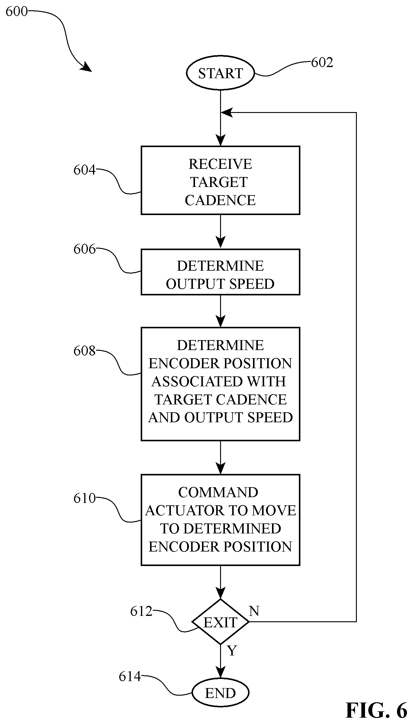
FIG. 6 is a process flow chart of an automatic transmission control method in accordance with the inventive embodiments described herein.
DETAILED DESCRIPTION OF THE PREFERRED EMBODIMENTS
Preferred embodiments of the present invention will now be described with reference to the accompanying figures, wherein like numerals refer to like elements throughout. The inventive systems and methods described here can be generally used with transmissions and variators disclosed in U.S. Pat. Nos. 6,241,636; 6,419,608; 6,689,012; and 7,011,600. Likewise, the inventive systems and methods disclosed here are related to transmissions, controllers, user interfaces, and vehicles or technology applications described in U.S. patent application Ser. Nos. 11/243,484; 11/543,311; 60/887,767; 60/895,713; and 60/914,633. The entire disclosure of each of these patents and patent applications is hereby incorporated herein by reference.
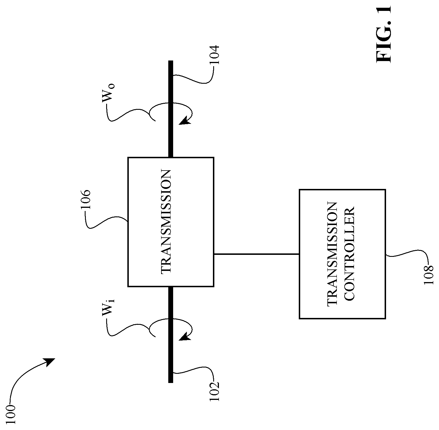
With reference to FIG. 1, a transmission control system 100 for maintaining a speed input constant is described now. In one embodiment, the system 100 includes an input shaft 102 and an output shaft 104 coupled to a transmission 106, which is coupled to a transmission controller 108. The input shaft 102 has an input speed w.sub.i, and the output shaft 106 has an output speed w.sub.o. A transmission speed ratio (SR) is defined as the output speed w.sub.o divided by the input speed w.sub.i (or equivalently, w.sub.i=w.sub.o/SR). During operation of the control system 100, in certain embodiments, as the output speed w.sub.o changes, the transmission controller 108 adjusts the SR to keep the input speed w.sub.i at a substantially constant value, or within a predetermined band of the input speed w.sub.i. Thus, in one embodiment, given a desired, constant input speed w.sub.i, and a detected output speed w.sub.o during operation, the controller 108 adjusts the transmission 104 to operate at a predetermined SR associated with the detected output speed w.sub.o.
The transmission 106 can be a conventional range box, gear box, planetary-gear-based transmission, traction-based transmission (such as a toroidal transmission, a ball planetary transmission, or any other continuously variable or infinitely variable transmission), or any combination thereof. The transmission controller 108 can include various integrated circuits, computer processors, logic modules, input and output interfaces, data structures, digital memory, power sources, actuators, sensors, encoders, servo mechanisms, etc. Preferably, in one embodiment, the transmission controller 108 includes a data structure that correlates vehicle output speed w.sub.o to data associated with SR of the transmission 106.
Passing to FIG. 2 now, an automatic transmission control system 200 includes a speed sensor 202 coupled to a digital processor 204. A digital memory 206 is placed in communication with the digital processor 204. The digital memory 206 has stored therein one or more matrices, or tables, or maps (hereinafter "tables 208") of output speed w.sub.o correlated with SR. In some instances, a logic module 209 is placed in communication with the digital process 204; the logic module 209 is provided with suitable programming and/or algorithms to cooperate with the digital processor 204 in processing inputs and providing outputs, such as determining a SR based on a sensed output speed w.sub.o and a data input associated with a desired constant input speed w.sub.i. In one embodiment, the system 200 includes an input device 210 coupled to the digital processor 204 to provide to the digital processor 204 a data input associated with a desired constant input speed target w.sub.c. In some embodiments of the system 200, an actuator 212 (or ratio adjuster mechanism) is coupled to the digital processor 204, whereby the digital processor 204 can control the actuator 212 to adjust the SR of a transmission 107, which in one instance can be a continuously variable transmission (CVT).
During operation, the speed sensor 202 provides to the digital processor 204 an indication of the output speed w.sub.o. The input device 210 provides to the digital processor 204 a target input speed w.sub.c. The digital processor 204, in cooperation with the logic module 209 and/or the tables 208, determines a SR associated with the indicated output speed w.sub.o and the target input speed w.sub.c. The digital processor 204 then commands the actuator 212 to adjust the operating speed ratio of the transmission 107 to the determined SR. In some embodiments, the target input speed w.sub.c can be substantially constant over a range of output speeds w.sub.o, resulting in the rider pedaling at a substantially constant cadence. In one embodiment, the input device 210 provides a map, or a selection indicative of such a map, of predetermined input speed w.sub.c values associated with output speed w.sub.o values.
Referencing FIG. 3 now, an automatic shifting bicycle system 300 is configured to keep a rider cadence within a narrow band of a rider selected cadence level. As used here, the term "cadence" refers to the pedaling speed of the rider (which is equivalent to the rotational speed of the bicycle cranks). In one embodiment, the bicycle system 300 includes a control unit 302 in communication with a speed sensor 304, an encoder position sensor 306, a user interface 308, a power source 310, and a reversible motor 312. In some instances, a gear reduction set 314 is coupled between the reversible motor 312 and a transmission 316. A bicycle wheel 318 and an input driver 320 are operationally coupled to the transmission 316. In some embodiments, the encoder position sensor 306 is coupled to the gear reduction set 314, and the speed sensor 304 operationally couples to the bicycle wheel 318 or to any rotating component associated therewith. The input driver 320 can be, or is operationally coupled to, a rear wheel sprocket, a chain, a front sprocket, a one-way clutch, a freewheel, etc. The power source 310 can be coupled to, or integrated with, anyone of the control unit 302, user interface 308, and motor 312. The power source 310 can be, for example, a battery, a dynamo, or any other suitable power generating or energy storing device.
In some embodiments, the control unit 302 includes a digital processor 322 that is in communication with a memory 324 and a logic module 326. The control unit 302 can additionally include a motor controller 328 that is in communication with the digital processor 322. It should be noted that the digital processor 322, memory 324, logic module 326, and the motor controller 328 need not be all integrated into one device or housed in a common housing. That is, in some embodiments, any one of the digital processor 322, memory 324, logic module 326, and motor controller 328 can be remotely located from any of the others; communication between or among them can be wired or wireless. The memory 324 is preferably provided with one more tables 330 having data that correlates values of output speed w.sub.o to values of SR. In one embodiment, as illustrated in FIG. 3, values of SR are represented by values associated with encoder positions; that is, an encoder position is representative of at least one SR state of the transmission 316. As used here, the term "encoder position" refers to a state of a detector and/or a sensor that is representative of a position of a component of the transmission 316, or of an internal or external component coupled to such a component of the transmission 316. For example, in one case, the encoder position is indicative of an angular position of a gear coupled to a shift rod of the transmission 316 such that the encoder position is indicative of an angular or axial position of the shift rod.
In one embodiment, the user interface 308 includes a display 332 and one or more operation button switches 334. The display 332 can be any suitable screen, or the like, for presenting a variety of graphical and/or alphanumerical information. The operation switches 334 can include one or more buttons or manipulators configured to allow an operator to enter data, make selections, or change values, for example. In some embodiments, the operation switches 334 allow the rider to select among modes of operation (for example, automatic continuous ratio adjustment, automatic stepped ratio adjustment, manual, etc.). The operation switches 334 can be configured to allow the rider to command different cadence levels while in automatic mode, or to request a SR adjustment while in manual mode.
Still referring to FIG. 3, during operation of the automatic shifting bicycle system 300, the user can use the user interface 308 to adjust the desired cadence level while operating the bicycle on a routine ride. The control unit 302 receives the cadence input, queries the memory 324, and in cooperation with the logic module 326 selects a corresponding table 330 associated with the cadence input. Hence, during normal operation of the bicycle, the user can select from among predetermined cadence level maps (that is, tables 330) by indicating a desired cadence value. The speed sensor 304 detects the speed of the bicycle wheel 318, which in some instances involves detecting a rotational speed of some other rotating component (such as the spokes of the bicycle wheel 318) that rotates at a speed indicative of the rotational speed of the bicycle wheel 318. Based upon the indicated cadence value and the detected speed of the bicycle wheel 318, the control unit 302 identifies from the tables 330 a SR, or encoder position, associated with the sensed speed of the bicycle wheel 318. The control unit 302, in cooperation with the motor controller 328, actuates the reversible motor 312 to adjust the transmission 316 to attain a speed ratio that substantially matches the SR identified from the table 330. As the control unit 302 adjusts the SR in response to changes to the speed of the bicycle wheel 318, the cadence of the rider is controlled to stay within a band of the rider's desired cadence level. For example, in some instances, the actual cadence level of the rider during steady state operation can be maintained at the desired cadence level plus or minus 10 revolutions-per-minute (rpm), or +/-5-rpm, or less than +/-2-rpm. In some embodiments, the automatic shifting bicycle system 300 can be configured with multiple automatic modes. The modes can be predetermined to control a rider's cadence in any desired manner over a range of output speeds. For example, in one such mode, a table 330 can be provided with cadence values, output speed values, and SR values associated such that over a first range of output speeds the cadence is controlled to a certain cadence value or a specific range of cadence values, while in a second range of output speeds the cadence is controlled to yet another cadence value or yet another specific range of cadence values.
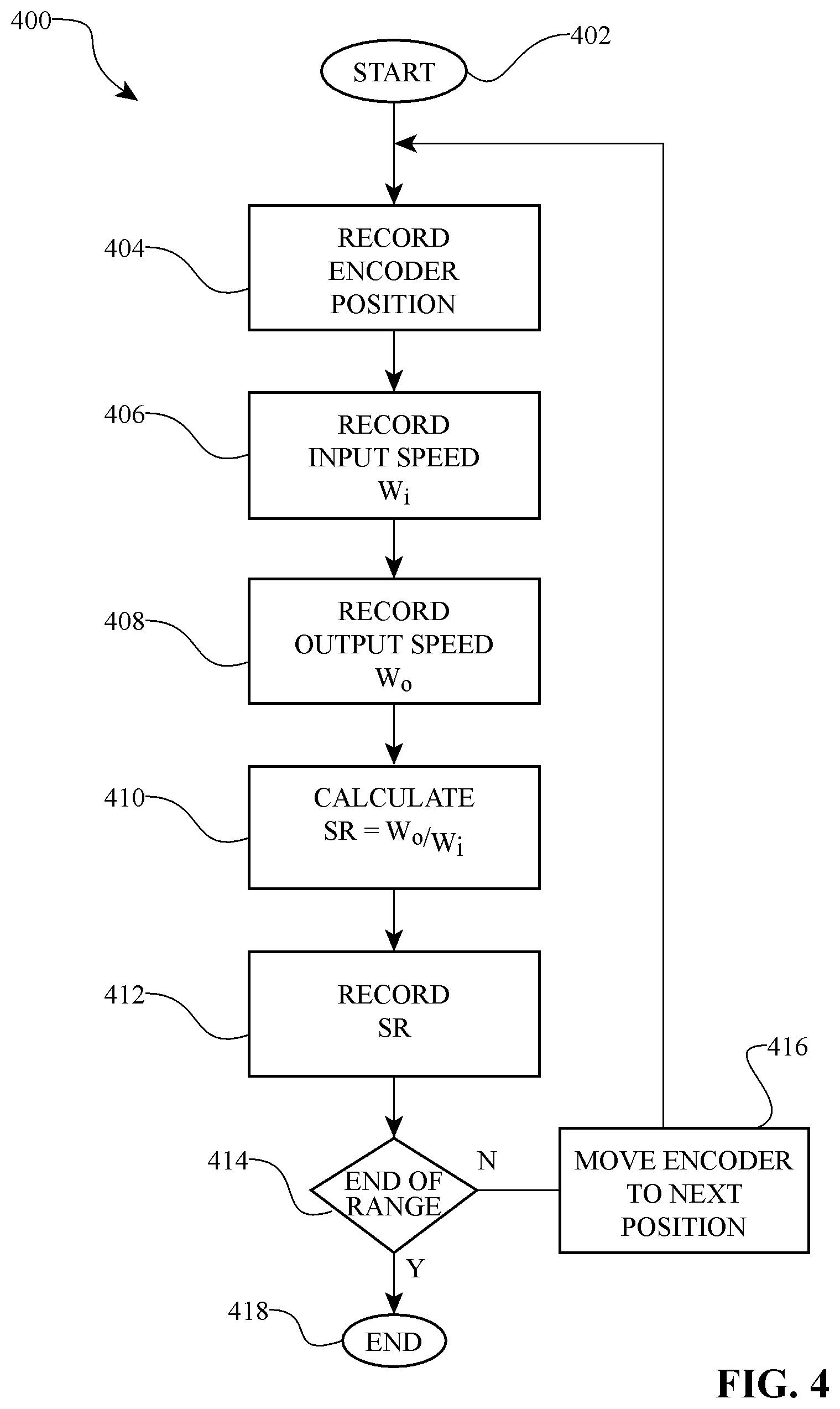
Referring to FIG. 4 now, a process 400 for generating data structures that can be used with a table 330 is described. In one embodiment, an exemplary transmission 316 is a compound variable planetary (CVP) of the ball-planetary, traction CVT type. An example of such devices is a NuVinci.TM. transmission. In such a transmission 316, the speed ratio between the speed of an input traction ring and the speed of an output traction ring is determined, at least in part, by a position of a shift rod. Hence, a position of an encoder of a servo mechanism can be correlated with a position of the shift rod, which effectively means that a position of the encoder is correlated with a speed ratio of the transmission 316. The process 400 starts at a state 402 after a servo mechanism having an encoder has been coupled to a transmission 316. At a state 404, an encoder position is recorded (and preferably stored in a data structure will be part of the table 330, for example). Moving to a state 406, an input speed of the transmission 316 is recorded, and at a state 408 an output speed of the transmission 316 is recorded. Passing to a state 410, a SR is calculated by dividing the output speed w.sub.o by the input speed w.sub.i. At a state 412, the SR is recorded (and preferably stored in a data structure that will be part of the table 330).
The process 400 then moves to a decision state 414 wherein it is determined whether the end of the range of the transmission 316 has been reached. For the current purposes, it is assumed that the range of encoder positions can be coextensive with the range of speed ratios of the transmission 316. When the transmission 316 is a continuously variable transmission there is an infinite number of transmission speed ratios within a given range; however, as a practical matter, both the encoder positions and the speed ratios of the transmission 316 will be each a finite set. If the end of the range of the transmission 316 has been reached, the process 400 continues to a state 416 at which the encoder is moved to the next encoder position. The process 400 then returns to the state 404 and records the new encoder position. The process 400 then repeats until at the decision state 414 it is determined that the end of the range of the transmission 316 has been reached, in which case the process 400 ends at a state 418.
Thus, a result of the process 400 is data structures correlating encoder positions with empirically determined speed ratios of the transmission 316. For a certain class of continuously variable transmissions, the speed ratio and encoder position data can be fit to a curve generally described by SR=A*exp(B*p), wherein A and B are constants or parameters characteristic of individual devices, and p is the encoder position. For example, for an exemplary CVP, A=0.4844 and B=0.0026. The data tables 330 can incorporate the encoder position and speed ratio data generated by the process 400.
Passing to FIG. 5A, an exemplary table 330 is shown and will now be discussed. The table 330 can include a vehicle speed data structure 502 with data associated with a vehicle speed. The table 330 can additionally include an encoder position data structure 504 with data associated with an encoder position. The vehicle speed data structure 502 and the encoder position data structure 504 correspond to one another as forming columns and rows of the table 330. Given a target constant input speed, a corresponding SR can be determined and tabulated as a requested SR data structure 506. In some cases, however, a requested SR is not available because, for example, such a SR is lower than the lowest SR the transmission 316 can provide. In such cases, the requested SR data structure 506 is used to produce a possible SR data structure 508. In the example illustrated in FIG. 5, the lowest possible SR available from the transmission 316 is 0.5; consequently, all the values of the requested SR data structure 506 below 0.5 are represented in the possible SR data structure 508 as 0.5. It follows that the corresponding lowest encoder position is then associated with the lowest possible SR ratio value in the table 330. Similarly, in some cases, the requested SR is higher than the highest possible SR of the transmission 316; hence, the entries in the requested SR data structure 506 that are higher than the highest possible SR of the transmission 316 are represented by the highest SR of the transmission 316 (which in the illustrative example is 1.615).
Of course, those values in the requested SR data structure 506 that fall within the possible range of speed ratios of the transmission 316 correspond to identical entries in the possible SR data structure 508. It should be noted that, other than for values falling below and above the possible range of the transmission 316, in the table 330 there is a unique encoder position value in the encoder position data structure 505 that corresponds to a unique SR value in the possible SR data structure 508. However, a speed range (rather than a unique speed) corresponds to a given encoder position. Hence, for a wheel speed of 58-rpm and less than 60-rpm in the vehicle speed data structure 502, there corresponds only one value of encoder position (that is, 24) and one value of possible speed ratio (that is, 0.52). The illustrative table 330 includes a cadence data structure 510 having data associated with a calculated cadence (using the expression w.sub.i=w.sub.o/SR). The cadence structure 510 need not be part of the table 330; however, the inclusion of the cadence structure 510 in the illustrative table 330 facilitates a demonstration of how the cadence can be maintained constant (as shown by the constant value of 50 in the cadence data structure 510) over the possible range of speed ratios of the transmission 316.
FIG. 5B illustrates yet another example of a map or table 331 of output speeds to SR that yield a predetermined rider cadence. In one embodiment, the table 331 includes a vehicle speed data structure 503 having data associated with an output, or vehicle, speed. The table 331 additionally includes an encoder position data structure 505 with data associated with an encoder position. The vehicle speed data structure 503 and the encoder position data structure 505 correspond to one another as forming columns and rows of the table 331. Given a desired, predetermined map of target input speeds, a possible SR data structure 509 is produced. A cadence data structure 511, which need not be part of the table 331, illustrates how the cadence is controlled over the range of vehicle speeds associated with the vehicle speed data structure 503. As can be seen in FIG. 5B, the cadence is allowed to rise to a first level (that is, 74.7-rpm), the SR is adjusted to 0.9 from 0.6, as the output speed changes from 0 to 100-rpm. The cadence drops to 51.1-rpm and is allowed to rise to 74.7-rpm again before at an output speed of 153-rpm the SR is adjusted from 0.9 to 1.4, at which the cadence drops to 48.8. As the output speed increases to 200-rpm, the cadence rises to 64-rpm, and the SR remains constant at 1.4. This is an example of automatically controlling a transmission such that the cadence is controlled relative to a three-speed ratio shifting scheme. Of course, similar maps can be provided for other automatic modes, such as 4-, 5-, 6-, 8-, or 9-speed, for example. In addition, the cadence ranges can be adjusted by moving shift events via the mapping, such as a range of 65-rpm to 90-rpm instead of 50-rpm to 75-rpm, for a given vehicle speed or range of vehicle speeds, for example. In some embodiments, the maps can have any desired relationship (for example, linear, exponential, inverse, etc.) between output speed and cadence.
Turning to FIG. 6, it will be described now a process 600 for controlling a transmission 316 so that a rider cadence is controlled to be within a band of a rider selected cadence level. The process 600 starts at a state 602 after a bicycle automatic shifting system 300, for example, has been turned on and initialized. The process 600 continues to a state 604 and receives an indication of a target constant cadence level. In one embodiment, the rider uses the user interface 308 to provide the target constant cadence level. The process 600 moves next to a state 606 where a speed of the bicycle is determined. In one embodiment, the speed sensor 304 detects the speed of the bicycle wheel 318. However, in other embodiments, the speed of the bicycle can be determined by measuring and/or sensing other characteristics or components of the bicycle, such as detecting a voltage, resistance, or current level on a dynamo (not shown) coupled to the bicycle wheel 318. The process 600 then continues to a state 608 wherein an encoder position associated with a bicycle speed and a target cadence is determined or identified. In one embodiment, the digital processor 322 cooperates with the memory 324 and the logic module 326 to query a table 330 and thereby select an encoder position that is correlated with a bicycle speed and a target cadence. At a state 610 of the process 600, an actuator is commanded to move to a position associated with the selected encoder position of state 608. In some embodiments, at a decision state 612 of the process 600, it is determined whether the process 600 should exit and end at a state 614 or loop back to the state 604 to receive a target cadence input. At the state 604, the process 600 can query whether the rider has commanded a new cadence level; if not, the process 600 continues using the cadence level initially entered. In one embodiment, the rider does not set the cadence level initially, but rather the control unit 302 is configured to use a default cadence level, such as 70-rpm for example. In yet other embodiments, a cadence-versus-output speed map (rather than a specific cadence value) can be provided to the process at the state 604. As previously discussed, such a map can include any kind of mapping associating cadence, output speed, and corresponding SR. At the state 614 of the process 600, the decision to exit can be based on a power off condition, a mode change command, or the like. For example, if the rider changes the mode from automatic mode to manual mode, the process 600 detects the new condition and exits at the state 614.
Those of skill will recognize that the various illustrative logical blocks, modules, circuits, and algorithm steps described in connection with the embodiments disclosed herein, including with reference to the automatic shifting bicycle system 300 may be implemented as electronic hardware, software stored on a computer readable medium and executable by a processor, or combinations of both. To clearly illustrate this interchangeability of hardware and software, various illustrative components, blocks, modules, circuits, and steps have been described above generally in terms of their functionality. Whether such functionality is implemented as hardware or software depends upon the particular application and design constraints imposed on the overall system. Skilled artisans may implement the described functionality in varying ways for each particular application, but such implementation decisions should not be interpreted as causing a departure from the scope of the present invention. For example, various illustrative logical blocks, modules, and circuits described in connection with the embodiments disclosed herein may be implemented or performed with a general purpose processor, a digital signal processor (DSP), an application specific integrated circuit (ASIC), a field programmable gate array (FPGA) or other programmable logic device, discrete gate or transistor logic, discrete hardware components, or any combination thereof designed to perform the functions described herein. A general purpose processor may be a microprocessor, but in the alternative, the processor may be any conventional processor, controller, microcontroller, or state machine. A processor may also be implemented as a combination of computing devices, e.g., a combination of a DSP and a microprocessor, a plurality of microprocessors, one or more microprocessors in conjunction with a DSP core, or any other such configuration. Software associated with such modules may reside in RAM memory, flash memory, ROM memory, EPROM memory, EEPROM memory, registers, a hard disk, a removable disk, a CD-ROM, or any other suitable form of storage medium known in the art. An exemplary storage medium is coupled to the processor such the processor can read information from, and write information to, the storage medium. In the alternative, the storage medium may be integral to the processor. The processor and the storage medium may reside in an ASIC. For example, in one embodiment, the control unit 302 comprises a processor (not shown). The processor of the control unit 302 may also be configured to perform the functions described herein with reference to one or both of the motor controller 328 and the user interface 308.
The foregoing description details certain preferred embodiments of the present invention and describes the best mode contemplated. It will be appreciated, however, that no matter how detailed the foregoing appears in text, the invention can be practiced in many ways. The scope of the present invention should therefore be construed only in accordance with the appended claims and any equivalents thereof.
* * * * *
D00000
D00001
D00002
D00003
D00004
D00005
D00006
D00007
XML
uspto.report is an independent third-party trademark research tool that is not affiliated, endorsed, or sponsored by the United States Patent and Trademark Office (USPTO) or any other governmental organization. The information provided by uspto.report is based on publicly available data at the time of writing and is intended for informational purposes only.
While we strive to provide accurate and up-to-date information, we do not guarantee the accuracy, completeness, reliability, or suitability of the information displayed on this site. The use of this site is at your own risk. Any reliance you place on such information is therefore strictly at your own risk.
All official trademark data, including owner information, should be verified by visiting the official USPTO website at www.uspto.gov. This site is not intended to replace professional legal advice and should not be used as a substitute for consulting with a legal professional who is knowledgeable about trademark law.