Side-saddle cantilever mast
Gupta , et al.
U.S. patent number 10,704,337 [Application Number 15/806,088] was granted by the patent office on 2020-07-07 for side-saddle cantilever mast. This patent grant is currently assigned to NABORS DRILLING TECHNOLOGIES USA, INC.. The grantee listed for this patent is Nabors Drilling Technologies USA, Inc.. Invention is credited to Ashish Gupta, Ryan Hause, Padira Reddy.


View All Diagrams
| United States Patent | 10,704,337 |
| Gupta , et al. | July 7, 2020 |
Side-saddle cantilever mast
Abstract
A side saddle slingshot drilling rig includes a right substructure and a left substructure, the substructures positioned generally parallel and spaced apart from each other. The right substructure includes a right lower box and a first strut, the first strut pivotably coupled to the drill rig floor and pivotably coupled to the right lower box. The left substructure includes a left lower box and a second strut, the second strut pivotably coupled to the drill rig floor and pivotably coupled to the left lower box. The side saddle slingshot drilling rig also includes a drill rig floor, the drill rig floor including a V-door. The side of the drill rig floor has the V-door defining the V-door side of the drill rig floor, the V-door side of the drill rig floor parallel to the right substructure. The side saddle slingshot drilling rig further includes a mast, the mast including an open side defining a mast V-door side. The open side is oriented to face perpendicular to the right substructure. The mast is pivotably coupled to the drill rig floor by one or more mast pivot points and one or more lower mast attachment points, the mast being pivotable in a direction parallel to the V-door side of the drill rig floor or the mast being pivotable in a direction perpendicular to V-door side of the drill rig floor. The mast includes two or more subunits, wherein the two or more subunits are pinned together.
| Inventors: | Gupta; Ashish (Houston, TX), Hause; Ryan (Houston, TX), Reddy; Padira (Richmond, TX) | ||||||||||
|---|---|---|---|---|---|---|---|---|---|---|---|
| Applicant: |
|
||||||||||
| Assignee: | NABORS DRILLING TECHNOLOGIES USA,
INC. (Houston, TX) |
||||||||||
| Family ID: | 62064329 | ||||||||||
| Appl. No.: | 15/806,088 | ||||||||||
| Filed: | November 7, 2017 |
Prior Publication Data
| Document Identifier | Publication Date | |
|---|---|---|
| US 20180128056 A1 | May 10, 2018 | |
Related U.S. Patent Documents
| Application Number | Filing Date | Patent Number | Issue Date | ||
|---|---|---|---|---|---|
| 62418656 | Nov 7, 2016 | ||||
| Current U.S. Class: | 1/1 |
| Current CPC Class: | E21B 15/00 (20130101); E04H 12/345 (20130101); E04H 12/34 (20130101); E21B 19/08 (20130101); E21B 15/006 (20130101) |
| Current International Class: | E04H 12/34 (20060101); E21B 15/00 (20060101); E21B 19/08 (20060101) |
References Cited [Referenced By]
U.S. Patent Documents
| 1733484 | October 1929 | Davis |
| 2332479 | October 1943 | Woolslayer et al. |
| 2345253 | March 1944 | Funk |
| 2347115 | April 1944 | Lewis |
| 2594847 | April 1952 | Bates et al. |
| 3028881 | April 1962 | Koomey et al. |
| 3228151 | January 1966 | Woolslayer et al. |
| 3255836 | June 1966 | Hoppmann et al. |
| 3433268 | March 1969 | Greer |
| 3483933 | December 1969 | Dyer et al. |
| 3576225 | April 1971 | Chambers |
| 3676984 | July 1972 | Clark |
| 3716149 | February 1973 | Scaggs |
| 3739853 | June 1973 | Wales |
| 3754361 | August 1973 | Branham et al. |
| 3802137 | April 1974 | Armstrong |
| 3851770 | December 1974 | Jenkins et al. |
| 3922825 | December 1975 | Eddy et al. |
| 3937334 | February 1976 | Bleyl et al. |
| 3942593 | March 1976 | Reeve, Jr. et al. |
| 3991887 | November 1976 | Trout |
| 4021978 | May 1977 | Busse et al. |
| 4029165 | June 1977 | Miller et al. |
| RE29541 | February 1978 | Russell |
| 4117941 | October 1978 | McCleskey et al. |
| 4221088 | September 1980 | Patterson |
| 4235566 | November 1980 | Beeman et al. |
| 4267675 | May 1981 | Cochran |
| 4290495 | September 1981 | Elliston |
| 4375892 | March 1983 | Jenkins et al. |
| 4403898 | September 1983 | Thompson |
| 4407629 | October 1983 | Willis |
| 4421179 | December 1983 | Boyadjieff |
| 4473977 | October 1984 | Reed |
| 4474254 | October 1984 | Etter et al. |
| 4478015 | October 1984 | Lawrence et al. |
| 4478291 | October 1984 | Futros |
| 4488708 | December 1984 | Frye |
| 4493382 | January 1985 | Collins et al. |
| 4587778 | May 1986 | Woolslayer et al. |
| 4744710 | May 1988 | Reed |
| 4757592 | July 1988 | Reed |
| 4759414 | July 1988 | Willis |
| 4821816 | April 1989 | Willis |
| 4823870 | April 1989 | Sorokan |
| 4834604 | May 1989 | Brittain et al. |
| 4837992 | June 1989 | Hashimoto |
| 4850439 | July 1989 | Lund |
| 4899832 | February 1990 | Bierscheid, Jr. |
| 4979578 | December 1990 | Landry |
| 5107940 | April 1992 | Berry |
| 5248005 | September 1993 | Mochizuki |
| 5305833 | April 1994 | Collins |
| 5375667 | December 1994 | Trevisani |
| 5492436 | February 1996 | Suksumake |
| 5921336 | July 1999 | Reed |
| 6161358 | December 2000 | Mochizuki et al. |
| 6343892 | February 2002 | Kristiansen |
| 6491477 | December 2002 | Bennett, Jr. et al. |
| 6581525 | June 2003 | Smith |
| 6634436 | October 2003 | Desai |
| 6779614 | August 2004 | Oser |
| 6848515 | February 2005 | Orr et al. |
| 6955223 | October 2005 | Orr et al. |
| 6962030 | November 2005 | Conn |
| 6976540 | December 2005 | Berry |
| 7228919 | June 2007 | Fehres et al. |
| 7255180 | August 2007 | Beato et al. |
| 7308953 | December 2007 | Barnes |
| 7357616 | April 2008 | Andrews et al. |
| 7401656 | July 2008 | Wood et al. |
| 7404697 | July 2008 | Thompson |
| 7600585 | October 2009 | Patton et al. |
| 7628229 | December 2009 | Wood et al. |
| 7765749 | August 2010 | Palidis |
| 7819207 | October 2010 | Cowan |
| 7832974 | November 2010 | Fikowski et al. |
| 7878254 | February 2011 | Abdollahi et al. |
| 7931076 | April 2011 | Ditta et al. |
| 7967540 | June 2011 | Wright et al. |
| 7992646 | August 2011 | Wright et al. |
| 8051930 | November 2011 | Barnes et al. |
| 8181698 | May 2012 | Springett et al. |
| 8250816 | August 2012 | Donnally et al. |
| 8297362 | October 2012 | Strider et al. |
| 8316588 | November 2012 | Cicognani |
| 3468753 | June 2013 | Donnally et al. |
| 8474216 | July 2013 | Goerner |
| 8516751 | August 2013 | Konduc et al. |
| 3549815 | October 2013 | Donnally et al. |
| 8555564 | October 2013 | Wasterval |
| 8561685 | October 2013 | Rodgers |
| 8573334 | November 2013 | Smith et al. |
| 8661743 | March 2014 | Flusche |
| 8720128 | May 2014 | Vogt |
| 8813436 | August 2014 | Donnally et al. |
| 8863449 | October 2014 | Donnally et al. |
| 8904716 | December 2014 | Donnally et al. |
| 8936424 | January 2015 | Barnes et al. |
| 8985238 | March 2015 | Sorokan et al. |
| 8985928 | March 2015 | Flusche |
| 8997435 | April 2015 | Reddy et al. |
| 9016004 | April 2015 | Vogt |
| 9027287 | May 2015 | Trevithick |
| 9091125 | July 2015 | Konduc et al. |
| 9091128 | July 2015 | Orgeron et al. |
| 9132871 | September 2015 | Crisp et al. |
| 9140080 | September 2015 | Flusche |
| 9151412 | October 2015 | Trevithick et al. |
| 9157286 | October 2015 | Richardson et al. |
| 9163462 | October 2015 | Donnally et al. |
| 9212481 | December 2015 | Stramandinoli |
| 9228394 | January 2016 | Wijning et al. |
| 9249626 | February 2016 | Flusche |
| 9260929 | February 2016 | Mark |
| 9267328 | February 2016 | Flusche |
| 9309728 | April 2016 | Reddy et al. |
| 9291012 | May 2016 | Wells, Sr. |
| 9353601 | May 2016 | Hause |
| 9382766 | July 2016 | Flusche |
| 9399890 | July 2016 | Mark |
| 9441423 | September 2016 | Donnally et al. |
| 9366053 | October 2016 | Thiessen et al. |
| 9464488 | October 2016 | Thiessen |
| 9476267 | October 2016 | Orgeron et al. |
| 9488014 | November 2016 | Sparkman |
| 9562407 | February 2017 | Magnuson |
| 9650840 | May 2017 | Cheng et al. |
| 9677298 | June 2017 | Konduc |
| 9708861 | July 2017 | Reddy |
| 9739098 | August 2017 | Fox |
| 9790751 | October 2017 | Reddy et al. |
| 9797196 | October 2017 | Taggart et al. |
| 9810027 | November 2017 | Reddy et al. |
| 9845813 | December 2017 | Shimizu et al. |
| 9879442 | January 2018 | Magnuson et al. |
| 10273708 | April 2019 | Holst et al. |
| 2002/0001255 | January 2002 | Flood et al. |
| 2003/0172599 | September 2003 | Frink |
| 2004/0211598 | October 2004 | Palidis |
| 2005/0193645 | September 2005 | Barnes |
| 2006/0213653 | September 2006 | Cunningham |
| 2008/0237170 | October 2008 | Altman et al. |
| 2009/0000218 | January 2009 | Lee et al. |
| 2009/0025980 | January 2009 | Callander et al. |
| 2009/0053013 | February 2009 | Maltby |
| 2009/0200856 | August 2009 | Chehade et al. |
| 2009/0272540 | November 2009 | Rodgers |
| 2010/0186960 | July 2010 | Reitsma et al. |
| 2010/0329823 | December 2010 | Baumler et al. |
| 2011/0072737 | March 2011 | Wasterval |
| 2011/0174545 | July 2011 | Hartke et al. |
| 2012/0168179 | July 2012 | Having et al. |
| 2012/0304553 | December 2012 | Konduc et al. |
| 2013/0269268 | October 2013 | Thiessen et al. |
| 2013/0305632 | November 2013 | Rivera, Sr. et al. |
| 2013/0330151 | December 2013 | Orgeron |
| 2014/0014417 | January 2014 | Smith et al. |
| 2014/0054097 | February 2014 | Bryant |
| 2014/0090333 | April 2014 | Vogt |
| 2014/0298735 | October 2014 | Vogt |
| 2015/0008038 | January 2015 | Folk |
| 2015/0143759 | May 2015 | Sparkman |
| 2015/0218891 | August 2015 | Padira |
| 2015/0315861 | November 2015 | Zachariasen et al. |
| 2016/0002947 | January 2016 | Wijning et al. |
| 2016/0130877 | May 2016 | Fortson et al. |
| 2016/0186495 | June 2016 | Flusche |
| 2016/0215592 | July 2016 | Helms et al. |
| 2016/0258215 | September 2016 | Holst |
| 2016/0258225 | September 2016 | Holst et al. |
| 2016/0280524 | September 2016 | Crisp et al. |
| 2016/0298394 | October 2016 | Padira et al. |
| 2016/0369570 | December 2016 | Reddy et al. |
| 2016/0376808 | December 2016 | Magnuson |
| 2017/0096832 | April 2017 | Robb |
| 2017/0106925 | April 2017 | Gupta et al. |
| 2017/0292334 | October 2017 | Reddy et al. |
| 2017/0328081 | November 2017 | Trevithick et al. |
| 2017/0350153 | December 2017 | Reddy et al. |
| 2018/0016851 | January 2018 | Reddy et al. |
| 2018/0030788 | February 2018 | Reddy et al. |
| 2018/0119496 | May 2018 | Reddy et al. |
| 2755483 | Nov 2010 | CA | |||
| 2753417 | Feb 2011 | CA | |||
| 201778661 | Mar 2011 | CN | |||
| 849533 | Sep 1952 | DE | |||
| 2751370 | Jul 2014 | EP | |||
| 2556042 | Jun 1985 | FR | |||
| 2016025521 | Feb 2016 | WO | |||
| 2016048458 | Mar 2016 | WO | |||
Other References
|
International Search Report and Written Opinion issued in PCT/US17/60429, dated Jan. 17, 2018, 10 pages. cited by applicant . Nabors 990 Proyecto Llanos.WMV; https://www.youtube.com/watch?v=6BgfgWumRIU, Nabors Rig 990 Chichimene, Colombia; Youtube.com; Aug. 10, 2011 (231 pages). cited by applicant . Drilling Contractor; "Nabors modular Rig 702 in Papua New Guinea--bound for ExxonMobil"; Drilling Contractor, in Drilling Rigs & Automation, News, Jul. 6, 2011; 2 pages; www.drillingcontractor.org. cited by applicant . Drilling Contractor; "Nabors to base all future land rigs on Minimum Area AC rig concept"; Drilling Contractor, in News, Aug. 22, 2011; 2 pages; www.drillingcontractor.org. cited by applicant . Sebastion, Simone; "Big drill soon begins long commute to work"; Houston Chronicle, Sunday, Jul. 3, 2011; 3 pages; www.chron.com. cited by applicant . Gaddy, Dean E., "Critical path analysis improves rig-moving procedures", Oil & Gas Journal, Nov. 16, 1998 (5 pages). cited by applicant. |
Primary Examiner: A; Phi D
Attorney, Agent or Firm: Locklar; Adolph
Parent Case Text
CROSS REFERENCE TO RELATED APPLICATIONS
This application is a U.S. non-provisional application which claims priority from U.S. provisional application No. 62/418,656, filed Nov. 7, 2016, which is incorporated by reference herein in its entirety.
Claims
The invention claimed is:
1. A side saddle slingshot drilling rig comprising: a right substructure and a left substructure, the substructures positioned generally parallel and spaced apart from each other; the right substructure comprises a right lower box and a first strut, the first strut pivotably coupled to the drill rig floor and pivotably coupled to the right lower box; the left substructure comprises a left lower box and a second strut, the second strut pivotably coupled to the drill rig floor and pivotably coupled to the left lower box; a drill rig floor, the drill rig floor including a V-door, the side of the drill rig floor including the V-door defining the V-door side of the drill rig floor, the V-door side of the drill rig floor parallel to the right substructure; and a mast, the mast including an open side defining a mast V-door side, the open side oriented to face perpendicular to the right substructure, the mast pivotably coupled to the drill rig floor by one or more mast pivot points and one or more lower mast attachment points, the mast being pivotable in a direction parallel to the V-door side of the drill rig floor or the mast being pivotable in a direction perpendicular to V-door side of the drill rig floor, the mast comprised of two or more subunits including: an upper mast subunit, the upper mast subunit including an upper mast section, a travelling block positioned within the upper mast section, the upper mast section having a V-door side, the upper mast subunit adapted to be transported such that the V-door side of the upper mast section is perpendicular to the ground; and a lower mast subunit, the lower mast subunit including a lower mast section, a top drive positioned within the lower mast section, the lower mast section having a V-door side, the lower mast-subunit adapted to be transported such that the V-door side of the lower mast section is perpendicular to the ground.
2. The side saddle slingshot drilling rig of claim 1, wherein the two or more subunits comprise a lower mast subunit, a middle mast subunit, and an upper mast subunit.
3. The side saddle slingshot drilling rig of claim 1 further comprising a catwalk assembly, the catwalk assembly including a catwalk and a slide, the catwalk mechanically connected to V-door side of the drill rig floor.
4. The side saddle slingshot drilling rig of claim 3, wherein the struts form a bar linkage between the lower boxes and the drill rig floor.
5. The side saddle slingshot drilling rig of claim 4, wherein the struts are adapted to allow motion of the drill rig floor relative to the lower boxes while maintaining the drill rig floor parallel to the lower boxes.
6. The side saddle slingshot drilling rig of claim 3, wherein the V-door side of the drill rig floor is parallel to the right substructure.
7. The side saddle slingshot drilling rig of claim 3, wherein the right and left lower boxes further comprise one or more hydraulic cylinders, the hydraulic cylinders mechanically coupled to one or more corresponding upper mast attachment points of the mast.
8. The side saddle slingshot drilling rig of claim 7, wherein the mast includes one or more braces positioned to brace the mast at the mast attachment points of the mast.
9. The side saddle slingshot drilling rig of claim 8, wherein the mast is pivotable in a direction away from the V-door side of the drill rig floor when lowered.
10. The side saddle slingshot drilling rig of claim 8, wherein the mast is pivotable in a direction toward the V-door side of the drill rig floor when lowered.
11. The side saddle slingshot drilling rig of claim 1 further comprising a choke house positioned on the drill rig floor or mechanically coupled to the right or left substructure.
12. The side saddle slingshot drilling rig of claim 11, wherein the choke house includes a choke manifold.
13. The side saddle slingshot drilling rig of claim 1 further comprising drill line spooler, the drilling rig spooler attached to lower box, the drill line spooler including a spool positioned on a spool bogie.
14. The side saddle slingshot drilling rig of claim 1 further comprising walkers, the walkers positioned within the lower boxes.
15. The side saddle slingshot drilling rig of claim 1 further comprising a mud gas separator, the mud gas separator mechanically coupled to the right or left substructure.
16. The side saddle slingshot drilling rig of claim 1 further comprising a stair tower, the stair tower mechanically coupled to the right substructure or left substructure.
17. The side saddle slingshot drilling rig of claim 1 further comprising a standpipe manifold, the standpipe manifold mechanically connected to the right substructure of left sub structure.
18. The side saddle slingshot drilling rig of claim 1 further comprising a drawworks, the drawworks mechanically connected to the left substructure or right substructure.
19. The side saddle slingshot drilling rig of claim 1 further comprising a hydraulic power unit, the hydraulic power unit mechanically connected to the left substructure or right sub structure.
20. The side saddle slingshot drilling rig of claim 1 further comprising an accumulator, the accumulator mechanically connected to the left substructure or right sub structure.
21. The side saddle slingshot drilling rig of claim 1 further comprising a drillers cabin, the drillers cabin mechanically connected to the left or right substructure.
Description
TECHNICAL FIELD
Field of the Disclosure
The present disclosure relates generally to drilling rigs, and specifically to rig structures for land drilling in the petroleum exploration and production industry.
Background of the Disclosure
Land-based drilling rigs may be configured to be traveled from location to location to drill multiple wells within the same area known as a wellsite. In certain situations, it is necessary to travel across an already drilled well for which there is a well-head in place. Further, mast placement on land-drilling rigs may have an effect on drilling activity. For example, depending on mast placement on the drilling rig, an existing well-head may interfere with the location of land-situated equipment such as, for instance, existing wellheads, and may also interfere with raising and lowering of equipment needed for operations. Traditional drilling rig mast designs typically include vertically erected bootstrap masts or cantilever masts transported with the "C" frame facing up or down.
SUMMARY
The present disclosure provides for a side saddle slingshot drilling rig. The side saddle slingshot drilling rig includes a right substructure and a left substructure, the substructures positioned generally parallel and spaced apart from each other. The right substructure includes a right lower box and a first strut, the first strut pivotably coupled to the drill rig floor and pivotably coupled to the right lower box. The left substructure includes a left lower box and a second strut, the second strut pivotably coupled to the drill rig floor and pivotably coupled to the left lower box. The side saddle slingshot drilling rig also includes a drill rig floor, the drill rig floor including a V-door. The side of the drill rig floor has the V-door defining the V-door side of the drill rig floor, the V-door side of the drill rig floor parallel to the right substructure. The side saddle slingshot drilling rig further includes a mast, the mast including an open side defining a mast V-door side. The open side is oriented to face perpendicular to the right substructure. The mast is pivotably coupled to the drill rig floor by one or more mast pivot points and one or more lower mast attachment points, the mast being pivotable in a direction parallel to the V-door side of the drill rig floor or the mast being pivotable in a direction perpendicular to V-door side of the drill rig floor. The mast includes two or more subunits, wherein the two or more subunits are pinned together.
The present disclosure also includes a method of transporting a mast. The method of transporting a mast includes transporting a lower mast subunit, the lower mast subunit including a lower mast section. A top drive is positioned within the lower mast section. The lower mast section has a V-door side. The lower mast-subunit is transported such that the V-door side of the lower mast section is perpendicular to the ground. The method of transporting a mast also includes transporting a middle mast subunit. The middle mast subunit includes a middle mast section, the middle mast section having a V-door side. The middle mast subunit is transported such that the V-door side of the middle mast section is perpendicular to the ground. The method of transporting a mast also includes transporting an upper mast subunit, the upper mast subunit including an upper mast section. A travelling block is positioned within the upper mast section. The upper mast section has a V-door side. The upper mast subunit is transported such that the V-door side of the upper mast section is perpendicular to the ground.
BRIEF DESCRIPTION OF THE DRAWINGS
The present disclosure is best understood from the following detailed description when read with the accompanying figures. It is emphasized that, in accordance with the standard practice in the industry, various features are not drawn to scale. In fact, the dimensions of the various features may be arbitrarily increased or reduced for clarity of discussion.
FIG. 1 depicts a perspective view of a side saddle slingshot drilling rig consistent with at least one embodiment of the present disclosure.
FIG. 2 depicts a side saddle slingshot drilling rig with the mast and drill rig floor in lowered positions consistent with at least one embodiment of the present disclosure.
FIG. 3 depicts a side saddle slingshot drilling rig with the mast in a raised position and the drill rig floor in the lowered position consistent with at least one embodiment of the present disclosure.
FIG. 4 depicts a side saddle slingshot drilling rig with the mast in a raised position and the drill rig floor in the raised position consistent with at least one embodiment of the present disclosure.
FIG. 5 depicts a side saddle slingshot drilling rig with the mast in a raised position and the drill rig floor in the raised position consistent with at least one embodiment of the present disclosure.
FIG. 6 is a side view of lower mast subunit consistent with at least one embodiment of the present disclosure.
FIG. 6A is an end view of lower mast subunit consistent with at least one embodiment of the present disclosure.
FIG. 7 is a side view of middle mast subunit consistent with at least one embodiment of the present disclosure.
FIG. 7A is an end view of middle mast subunit consistent with at least one embodiment of the present disclosure.
FIG. 8 is a side view of upper mast subunit consistent with at least one embodiment of the present disclosure.
FIG. 8A is an end view of upper mast subunit consistent with at least one embodiment of the present disclosure.
FIG. 9 is a schematic depiction of a filed having wellheads.
DETAILED DESCRIPTION
It is to be understood that the following disclosure provides many different embodiments, or examples, for implementing different features of various embodiments. Specific examples of components and arrangements are described below to simplify the present disclosure. These are, of course, merely examples and are not intended to be limiting. In addition, the present disclosure may repeat reference numerals and/or letters in the various examples. This repetition is for the purpose of simplicity and clarity and does not in itself dictate a relationship between the various embodiments and/or configurations discussed.
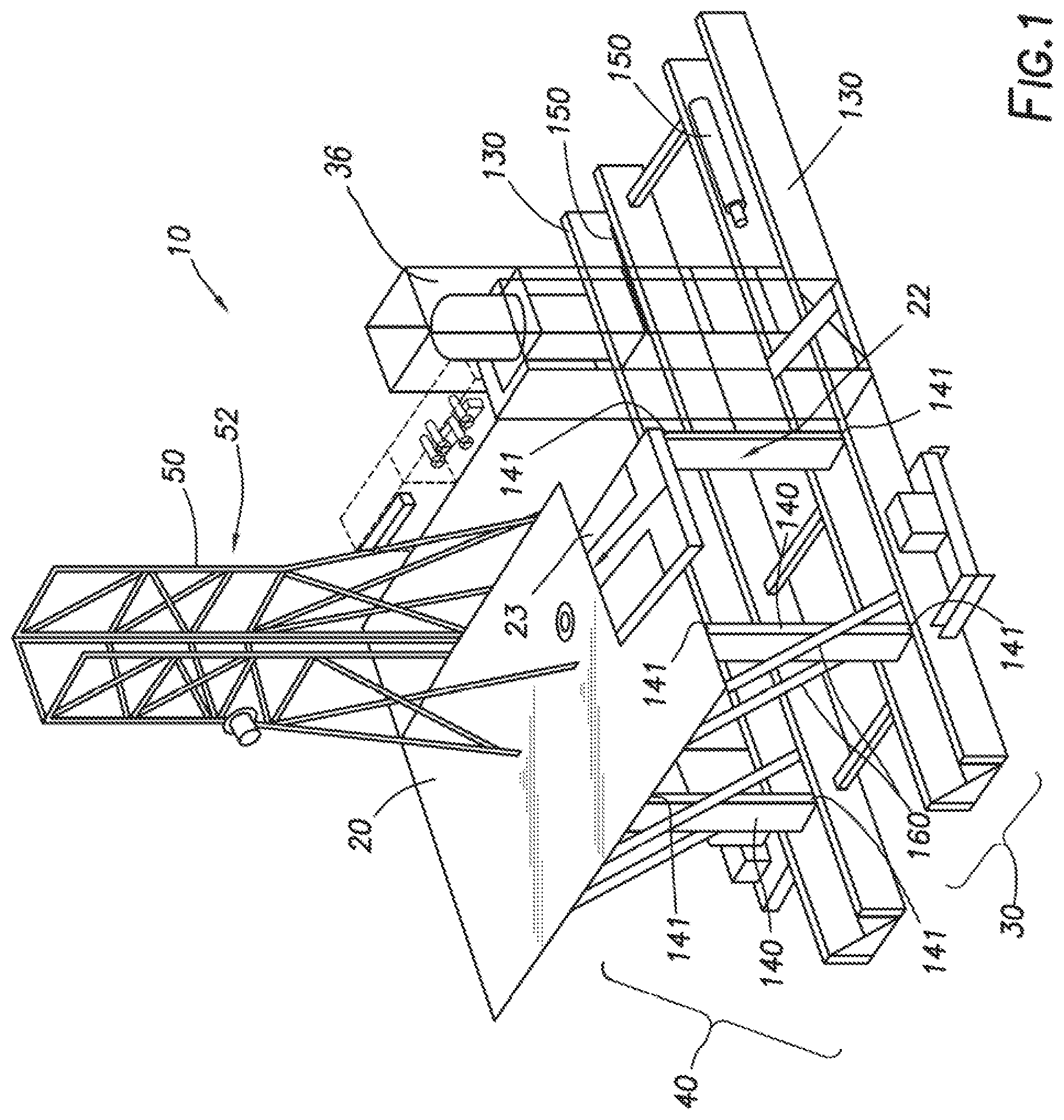
FIG. 1 depicts a perspective view of side saddle slingshot drilling rig 10 in a mast raised position. In some embodiments, side saddle slingshot drilling rig 10 may include drill rig floor 20, right substructure 30, left substructure 40, and mast 50. Right and left substructures 30, 40 may support drill rig floor 20. Right and left substructures 30, 40 may be generally parallel and spaced apart in the right-left direction. As would be understood by one having ordinary skill in the art with the benefit of this disclosure, the terms "right" and "left" as used herein are only used to refer to each separate substructure to simplify discussion, and are not intended to limit this disclosure in any way. Right and left substructures 30, 40, may each include one or more lower boxes 130 and one or more struts 140. Drill rig floor 20 may be mechanically coupled to lower boxes 130 by struts 140. Struts 140 may be pivotably coupled to drill rig floor 20 and to one or more lower boxes 130, where struts 140 are pivotably coupled to drill rig floor 20 at pivot points 141. Lower boxes 130 may be generally parallel to each other and spaced apart in the left-right direction. In some embodiments, struts 140 may be coupled to drill rig floor 20 and lower boxes 130 such that struts 140 form a bar linkage between lower boxes 130 and drill rig floor 20, allowing relative motion of drill rig floor 20 relative to lower boxes 130 while maintaining drill rig floor 20 parallel to lower boxes 130 as further discussed herein below. In some embodiments, right substructure 30 may include a lower box 130 referred to herein as a right lower box. In some embodiments, left substructure 40 may include a lower box 130 referred to herein as a left lower box. Although shown in FIG. 1 as having a long side and a short side, lower boxes 130 may be of any shape including a square.
In some embodiments, drill rig floor 20 may include V-door 23. The side of drill rig floor 20 at which V-door 23 is referred to herein as V-door side 22. In some embodiments, V-door side 22 of side saddle slingshot drilling rig 10 may face the right substructure 30. In some embodiments, V-door 23 may be oriented to face perpendicular to right substructure 30. In some embodiments, V-door side 22 may be parallel to right substructure 30.
In some embodiments, mast 50 may include mast V-door side 52, defined as the open side of mast 50. In some embodiments, mast V-door side 52 may be aligned with V-door 23. In some embodiments, mast V-door side 52 may be oriented to face perpendicular to right substructure 30. FIG. 2 depicts side saddle slingshot drilling rig 10 consistent with at least one embodiment of the present disclosure. As shown in FIG. 2, in some embodiments, mast 50 may be pivotably coupled to drill rig floor 20 by one or more mast pivot points 60 and one or more lower mast attachment points 62. Lower mast attachment points 62 may be disconnected, allowing mast 50 to pivot on mast pivot points 60 as further discussed herein below. In some such embodiments, mast 50 may thus be lowerable from the upright position depicted in FIG. 1 to the lowered position shown in FIG. 2. FIG. 2 further depicts drawworks 38, wherein drawworks 38 is mechanically coupled to left substructure 40. In other embodiments, drawworks 38 is mechanically coupled to right substructure 30. In addition, FIG. 2 depicts racking board 48 attached to mast 50.
In some embodiments, to move mast 50 from the lowered position to the mast raised position, mast 50 may be transported to side saddle slingshot drilling rig 10 and may be mechanically coupled to drill rig floor 20 by pivot points 60 using, for example and without limitation, one or more pins. One or more hydraulic cylinders 150 may be mechanically coupled to mast 50. In some embodiments, hydraulic cylinders 150 may mechanically couple to one or more corresponding upper mast attachment points 56 positioned on mast 50. In some embodiments, mast 50 may be moved into the mast raised position by extending hydraulic cylinders 150 such that mast 50 moves from a horizontal position as depicted in FIG. 2 to a vertical position as depicted in FIG. 3. Mast 50 may be mechanically coupled to drill rig floor 20 by lower mast attachment points 62 using, for example and without limitation, one or more pins to support and retain mast 50 in the vertical position. In some embodiments, hydraulic cylinders 150 may be detached from upper mast attachment points 56 once mast 50 is secured to drill rig floor 20 by lower mast attachment points 62. In some embodiments, hydraulic cylinders 150 may be mechanically coupled to drill rig floor lifting points 24. Hydraulic cylinders 150 may then be extended to move drill rig floor 20 from the lowered position as depicted in FIG. 3 to the raised position as depicted in FIGS. 1, 4. Hydraulic cylinders 150 may then be disconnected from drill rig floor lifting points 24, retracted and stored in right and left substructures 30, 40. In some embodiments, hydraulic cylinders 150 may be utilized to transition side saddle slingshot drilling rig 10 from the raised position to the mast raised position and the lowered position by reversing the previously described operations. FIGS. 3, 4, and 5 further depict drillers cabin 180 mechanically coupled to right substructure 30. In other embodiments, drillers cabin 180 may be mechanically coupled to left substructure 40 or drill rig floor 20. In certain embodiments, drillers cabin 180 may house a control center, such as an MCC, and a variable frequency drive (VFD).
As further shown in FIG. 2, in some embodiments, mast 50 is pivotably lowerable in a direction parallel to V-door side 22 of drill rig floor 20. In such an embodiment, mast V-door side 52 may be oriented to face horizontally, i.e., mast V-door side 52 may be may be perpendicular to ground 15, when mast 50 is in the lowered position. In an alternative embodiment, mast 50 is pivotable in a direction away from the V-door side 22 when lowered. In yet another embodiment, mast 50 is pivotable in a direction toward the V-door side 22 when lowered.
In some embodiments, components of mast 50 including, for example and without limitation, top drive 53, traveling block 54, and crown assembly 55 may be retained within mast 50 when mast 50 is in the lowered position without additional components. In some embodiments, mast 50 may be removeable from drill rig floor 20 and transported horizontally. In some such embodiments, top drive 53, traveling block 54, and crown assembly 55 may be retained within mast 50 when mast 50 is transported.
FIG. 2 further depicts choke house 160 mechanically coupled to right substructure 30. In other embodiments, choke house 160 may be mechanically coupled to left substructure 40 or positioned on drill floor 20. Choke house 160 houses choke manifold 162 which includes set of high pressure valves and at least two chokes. Positioned adjacent to and attached to lower box 130 is drill line spooler 170. As further described below, drill line spooler 170 may include spool 171 positioned on spool bogie 172.
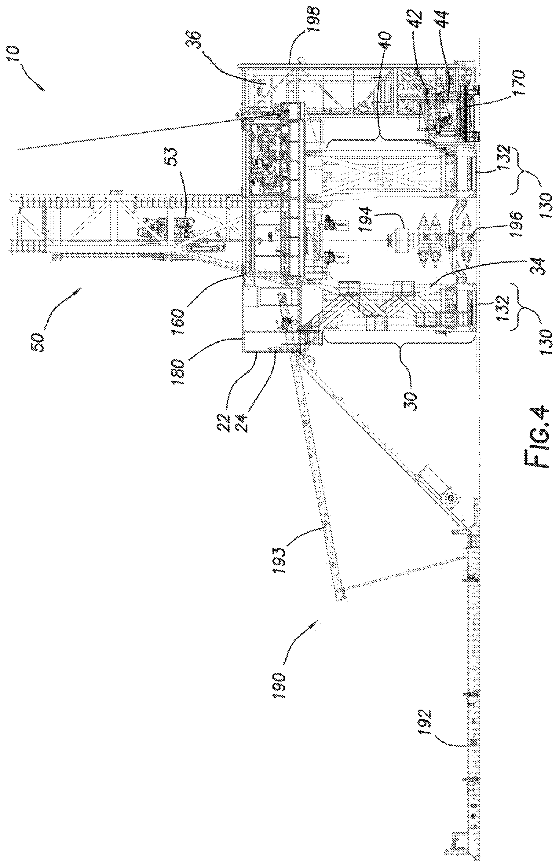
FIGS. 4 and 5 depict side saddle slingshot drilling rig 10 with mast 50 and drill rig floor 20 in raised positions. FIGS. 4 and 5 further depict catwalk assembly 190 mechanically connected to V-door side 22 of drill rig floor 20. Catwalk assembly 190 may include catwalk 192 and slide 193. Also shown in FIG. 4 is wellhead 196 including BOP 194. As shown in FIG. 4 lower boxes 130 may be positioned on to the right and left side of wellhead 196, with right substructure 30 and left substructure 40 of sufficient height to allow drill rig floor 20 to clear BOP 194. Walkers 132 may be positioned within lower boxes 130. FIGS. 4 and 5 further depict mud gas separator 198. Mud gas separator 198 may be connected to drill rig floor 20, such as by hanging mud gas separator 198 from drill rig floor 20. In other embodiments, mud gas separator 198 may be connected to left substructure 40. In yet other embodiments, mud gas separator 198 may be connected to right substructure 30. In certain embodiments, mud gas separator 198 may be positioned opposite V-door 23 on side saddle slingshot drilling rig 10.
FIGS. 4 and 5 further depict stair tower 34 mechanically coupled to right substructure 30. In other embodiments, stair tower 34 may be mechanically coupled to left substructure 40. FIGS. 4 and 5 also depict standpipe manifold 36 mechanically connected to left substructure 40. In other embodiments, such as that shown in FIG. 1, standpipe manifold 36 is mechanically connected to right substructure 30. FIGS. 4 and 5 also depict hydraulic power unit 42 mechanically connected to left substructure 40. In other embodiments, hydraulic power unit 42 is mechanically connected to right substructure 30. In addition, FIGS. 4 and 5 depict accumulator 44 mechanically connected to left substructure 40. In other embodiments, accumulator 44 is mechanically connected to right sub structure 30.
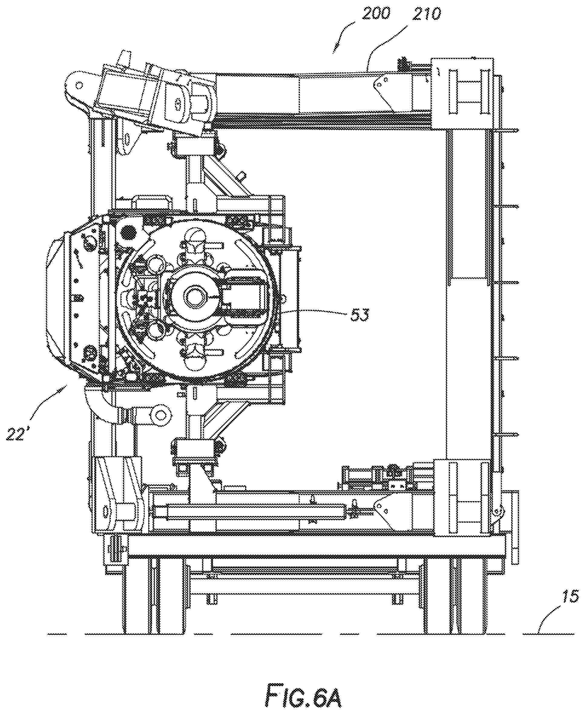
In certain embodiments, mast 50 may be composed of two or more subunits, wherein the subunits may be independently transportable. FIGS. 6, 7, and 8 depict lower mast subunit 200, middle mast subunit 300, and upper mast subunit 400, respectively. As shown in FIG. 6, lower mast subunit 200 includes lower mast section 210. In some embodiments, top drive 53 may be positioned within lower mast subunit 200 during transportation of lower mast subunit 200. During transport, lower mast subunit 200 may also include lower mast subunit bogie 220. Lower mast subunit bogie 220 is shown with five sets of wheels 222, although this number of sets of wheels 222 is non-limiting. Lower mast subunit bogie 220 may be mechanically connected to lower mast section 210 during transport and may be removeable thereafter. In certain embodiments, as further shown in FIG. 6, lower mast subunit gooseneck 230 may be mechanically connected to lower mast section 210 during transport and removeable thereafter. In an alternative embodiment, lower mast subunit gooseneck 230 is not removed. Lower mast subunit gooseneck 230 may be adapted to mechanically connect with tractor 250 for transport.
FIG. 6A is an end view of lower mast subunit 200. As shown in FIG. 6A, V-door side 22' of lower mast section 210 is perpendicular to ground 15, i.e., V-door side 22' of lower mast section 210 is vertical during transport. FIG. 6A also depicts one non-limiting position of top drive 53 within lower mast section 210.
FIG. 7 depicts middle mast subunit 300, which includes middle mast section 310. During transport, middle mast subunit 300 unit may also include middle mast subunit bogie 320. Middle mast subunit bogie 320 is shown with three sets of wheels 322, although this number of sets of wheels 322 is non-limiting. Middle mast subunit bogie 320 may be mechanically connected to middle mast section 310 during transport and may be removeable thereafter. In certain embodiments, as further shown in FIG. 7, middle mast subunit gooseneck 330 may be mechanically connected to middle mast section 310 during transport and removeable thereafter. In an alternative embodiment, middle mast subunit gooseneck 330 is not removed. Middle mast subunit gooseneck 330 may be adapted to mechanically connect with tractor 350 for transport. FIG. 7A is an end view of middle mast subunit 300. As shown in FIG. 7A, V-door side 22'' of middle mast section 310 is perpendicular to ground 15, i.e., V-door side 22'' of middle mast section 310 is vertical during transport. In certain embodiments, middle mast section 310 may be transported with racking board 48 in a folded configuration.
FIG. 8 depicts upper mast subunit 400, which includes upper mast section 410. During transport, upper mast subunit 400 may also include upper mast subunit bogie 420. Upper mast subunit bogie 420 is shown with two sets of wheels 422, although this number of sets of wheels 422 is non-limiting. Upper mast subunit bogie 420 may be mechanically connected to upper mast section 410 during transport and may be removeable thereafter. In certain embodiments, as further shown in FIG. 8, upper mast subunit kingpin 430 may be mechanically connected to upper mast section 410. Upper mast subunit kingpin 430 may be adapted to mechanically connect with tractor 450 for transport. In certain embodiments, as shown in FIG. 8, crown assembly 55 may be positioned atop upper mast section 410 and connected by drill line 57 to travelling block 54. Travelling block 54 may be transported within upper mast section 410. In some embodiments, upper mast subunit 400 may be mechanically connected to drill line spooler 170 during transport. Drill line spooler 170 may be mounted on spool bogie 172 such that upper mast subunit 400 and drill line spooler 170 are transported together by tractor 450. In some embodiments, drill line 57 may remain operationally coupled to drill line spooler 170 and the sheaves of crown assembly 55 and travelling block 54 during transport. By transporting drill line spooler 170 with upper mast subunit 400 and by keeping drill line 57 operationally coupled to crown assembly 55 and travelling block 54, the time required to rig-up or rig-down mast 50 may be reduced compared to a mast 50 that transports these components separately or without drill line 57 operatively connected thereto. Although spool bogie 172 is shown with three wheels 175, this number of wheels 175 is non-limiting and any number of wheels 175 may be used.
FIG. 8A is an end view of upper mast subunit 400. As shown in FIG. 8A, V-door side 22''' of upper mast section 410 is perpendicular to ground 15, i.e., V-door side 22''' of upper mast section 410 is vertical during transport.
In some embodiments, in order to assemble mast 50, lower mast subunit 200, middle mast subunit 300, and upper mast subunit 400 may be transported to side saddle slingshot drilling rig 10. Lower mast subunit 200, middle mast subunit 300, and upper mast subunit 400 may be positioned horizontally in alignment with each other and may be joined to form mast 50. In some embodiments, lower mast subunit 200, middle mast subunit 300, and upper mast subunit 400 may be joined by, for example and without limitation, one or more pinned connections. Mast 50 may then be coupled to mast pivot points 60 and raised as discussed herein above. Drill line 57 may be operatively coupled to a hoisting device such as a drawworks, and travelling block 54 may be lowered therewith and coupled to top drive 53.
In some embodiments, mast 50 may be lowered and disassembled to, for example and without limitation, transport mast 50. In such an operation, top drive 53 may be lowered using travelling block 54 such that top drive 53 is positioned within lower mast subunit 200. Top drive 53 may then be secured to lower mast subunit 200. Travelling block 54 may then be raised until travelling block 54 is positioned within upper mast subunit 400. Mast 50 may then be lowered as discussed herein above, decoupled from mast pivot points 60, and separated into lower mast subunit 200, middle mast subunit 300, and upper mast subunit 400. In some embodiments, bogeys 220, 320, and 420 may be coupled to the respective mast subunits 200, 300, and 400, and mast subunits 200, 300, and 400 may be transported separately as discussed herein above. In some embodiments, drill line spooler 170 may be coupled to upper mast subunit 400 such that drill line spooler 170 is transported with upper mast subunit 400.
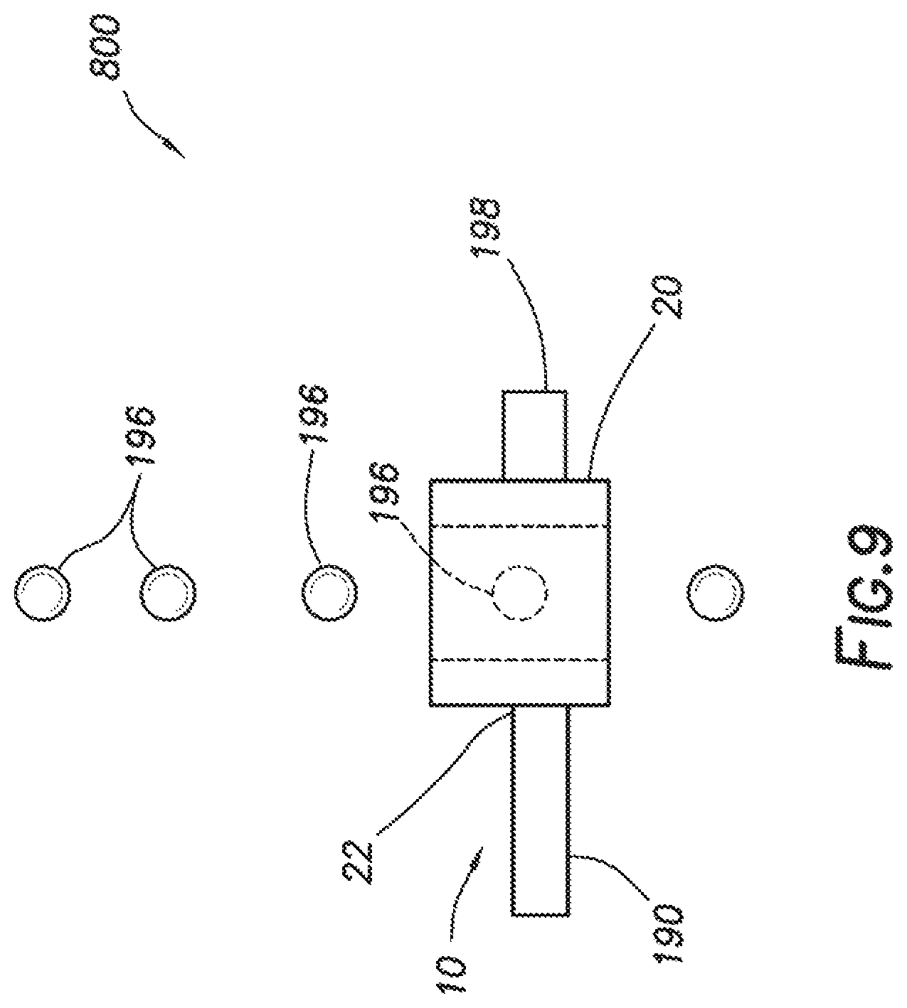
FIG. 9 depicts field 800 having a plurality of wellheads 196 arranged in a row. As shown in FIG. 9, V-door side 22 is positioned parallel to the row of wellheads 196. Unlike conventional rigs, side saddle slingshot drilling rig 10 may skid or walk over a row of wellheads 196 without rig up and rig down time. By positioning the V-door side perpendicular to right substructure 30 or left substructure 40, catwalk assembly 190 is positioned away from an adjacent wellhead instead of across or on top of an adjacent wellhead. In certain embodiments, as lower mast subunit 200, middle mast subunit 300, and upper mast subunit 400 are transported horizontally, the mast may be raised without requiring breakdown of catwalk assembly 190.
The foregoing outlines features of several embodiments so that a person of ordinary skill in the art may better understand the aspects of the present disclosure. Such features may be replaced by any one of numerous equivalent alternatives, only some of which are disclosed herein. One of ordinary skill in the art should appreciate that they may readily use the present disclosure as a basis for designing or modifying other processes and structures for carrying out the same purposes and/or achieving the same advantages of the embodiments introduced herein. One of ordinary skill in the art should also realize that such equivalent constructions do not depart from the spirit and scope of the present disclosure and that they may make various changes, substitutions, and alterations herein without departing from the spirit and scope of the present disclosure.
* * * * *
References
D00000
D00001
D00002
D00003
D00004
D00005
D00006
D00007
D00008
D00009
D00010
D00011
D00012
XML
uspto.report is an independent third-party trademark research tool that is not affiliated, endorsed, or sponsored by the United States Patent and Trademark Office (USPTO) or any other governmental organization. The information provided by uspto.report is based on publicly available data at the time of writing and is intended for informational purposes only.
While we strive to provide accurate and up-to-date information, we do not guarantee the accuracy, completeness, reliability, or suitability of the information displayed on this site. The use of this site is at your own risk. Any reliance you place on such information is therefore strictly at your own risk.
All official trademark data, including owner information, should be verified by visiting the official USPTO website at www.uspto.gov. This site is not intended to replace professional legal advice and should not be used as a substitute for consulting with a legal professional who is knowledgeable about trademark law.