Closure devices for medical devices and methods
Burns , et al.
U.S. patent number 10,702,409 [Application Number 14/173,685] was granted by the patent office on 2020-07-07 for closure devices for medical devices and methods. This patent grant is currently assigned to Boa Technology Inc.. The grantee listed for this patent is Boa Technology Inc.. Invention is credited to Robert Burns, James Capra, Mark Soderberg, Tamara White.


View All Diagrams
| United States Patent | 10,702,409 |
| Burns , et al. | July 7, 2020 |
Closure devices for medical devices and methods
Abstract
Closure devices that may be used for various articles, such as braces, medical devices, shoes, clothing, apparel, and the like. The closure devices may include a tightening mechanism that may function as a handle that allows an individual to wrap an article around body part, couple the article about the body part, and then tension or tighten the article using a single hand.
| Inventors: | Burns; Robert (Denver, CO), Capra; James (Steamboat Springs, CO), White; Tamara (Denver, CO), Soderberg; Mark (Conifer, CO) | ||||||||||
|---|---|---|---|---|---|---|---|---|---|---|---|
| Applicant: |
|
||||||||||
| Assignee: | Boa Technology Inc. (Denver,
CO) |
||||||||||
| Family ID: | 51259852 | ||||||||||
| Appl. No.: | 14/173,685 | ||||||||||
| Filed: | February 5, 2014 |
Prior Publication Data
| Document Identifier | Publication Date | |
|---|---|---|
| US 20140221889 A1 | Aug 7, 2014 | |
Related U.S. Patent Documents
| Application Number | Filing Date | Patent Number | Issue Date | ||
|---|---|---|---|---|---|
| 61761059 | Feb 5, 2013 | ||||
| Current U.S. Class: | 1/1 |
| Current CPC Class: | A61F 5/0102 (20130101) |
| Current International Class: | A61F 5/01 (20060101) |
References Cited [Referenced By]
U.S. Patent Documents
| 59332 | October 1866 | White et al. |
| 80834 | August 1868 | Prussia |
| 117530 | August 1871 | Foote |
| 228946 | June 1880 | Schulz |
| 230759 | August 1880 | Drummond |
| 379113 | March 1888 | Hibberd |
| 746563 | December 1903 | McMahon |
| 819993 | May 1906 | Haws et al. |
| 908704 | January 1909 | Sprinkle |
| 1060422 | April 1913 | Bowdish |
| 1062511 | May 1913 | Short |
| 1083775 | January 1914 | Thomas |
| 1090438 | March 1914 | Worth et al. |
| 1170472 | February 1916 | Barber |
| 1288859 | December 1918 | Feller et al. |
| 1390991 | September 1921 | Fotchuk |
| 1393188 | October 1921 | Whiteman |
| 1469661 | February 1922 | Migita |
| 1412486 | April 1922 | Paine |
| 1416203 | May 1922 | Hobson |
| 1429657 | September 1922 | Trawinski |
| 1481903 | April 1923 | Hart |
| 1466673 | September 1923 | Solomon et al. |
| 1530713 | February 1924 | Clark |
| 1502919 | July 1924 | Seib |
| 1862047 | June 1932 | Boulet et al. |
| 1995243 | June 1934 | Clarke |
| 2088851 | August 1937 | Gantenbein |
| 2109751 | March 1938 | Matthias et al. |
| 2124310 | September 1938 | Murr, Jr. |
| 2316102 | April 1943 | Preston |
| 2539026 | January 1951 | Mangold |
| 2611940 | September 1952 | Cairns |
| 2673381 | March 1954 | Dueker |
| 2907086 | October 1959 | Ord |
| 2991523 | July 1961 | Del Conte |
| 3028602 | April 1962 | Miller |
| 3035319 | May 1962 | Wolff |
| 3106003 | October 1963 | Herdman |
| 3112545 | December 1963 | Williams |
| 3122810 | March 1964 | Lawrence et al. |
| 3163900 | January 1965 | Martin |
| D200394 | February 1965 | Hakim |
| 3169325 | February 1965 | Fesl |
| 3193950 | July 1965 | Liou |
| 3197155 | July 1965 | Chow |
| 3221384 | December 1965 | Aufenacker |
| 3276090 | October 1966 | Nigon |
| D206146 | November 1966 | Hendershot |
| 3345707 | October 1967 | Rita |
| D210649 | April 1968 | Getgay |
| 3401437 | September 1968 | Christpohersen |
| 3430303 | March 1969 | Perrin et al. |
| 3445901 | May 1969 | Kamper |
| 3491465 | January 1970 | Martin |
| 3545106 | December 1970 | Martin |
| 3618232 | November 1971 | Shnuriwsky |
| 3668791 | June 1972 | Salzman et al. |
| 3678539 | July 1972 | Graup |
| 3703775 | November 1972 | Gatti |
| 3729779 | May 1973 | Porth |
| 3738027 | June 1973 | Schoch |
| 3793749 | February 1974 | Gertsch et al. |
| 3808644 | May 1974 | Schoch |
| 3934346 | January 1976 | Sasaki et al. |
| 3975838 | August 1976 | Martin |
| 4084267 | April 1978 | Zadina |
| 4130949 | December 1978 | Seidel |
| 4142307 | March 1979 | Martin |
| 4227322 | October 1980 | Annovi |
| 4261081 | April 1981 | Lott |
| 4267622 | May 1981 | Burnett-Johnston |
| 4408403 | October 1983 | Martin |
| 4417703 | November 1983 | Weinhold |
| 4433456 | February 1984 | Baggio |
| 4463761 | August 1984 | Pols et al. |
| 4480395 | November 1984 | Schoch |
| 4507878 | April 1985 | Semouha |
| 4551932 | November 1985 | Schoch |
| 4555830 | December 1985 | Petrini et al. |
| 4574500 | March 1986 | Aldinio et al. |
| 4616432 | October 1986 | Bunch et al. |
| 4616524 | October 1986 | Biodia |
| 4619057 | October 1986 | Sartor et al. |
| 4620378 | November 1986 | Sartor |
| 4631839 | December 1986 | Bonetti et al. |
| 4631840 | December 1986 | Gamm |
| 4633599 | January 1987 | Morell et al. |
| 4644938 | February 1987 | Yates et al. |
| 4654985 | April 1987 | Chalmers |
| 4660300 | April 1987 | Morell et al. |
| 4660302 | April 1987 | Arieh et al. |
| 4680878 | July 1987 | Pozzobon et al. |
| 4719670 | January 1988 | Kurt |
| 4719709 | January 1988 | Vaccari |
| 4719710 | January 1988 | Pozzobon |
| 4722477 | February 1988 | Floyd |
| 4741115 | May 1988 | Pozzobon |
| 4748726 | June 1988 | Schoch |
| 4760653 | August 1988 | Baggio |
| 4780969 | November 1988 | White, Jr. |
| 4787124 | November 1988 | Pozzobon et al. |
| 4790081 | December 1988 | Benoit et al. |
| 4796829 | January 1989 | Pozzobon et al. |
| 4799297 | January 1989 | Baggio et al. |
| 4802291 | February 1989 | Sartor |
| 4811503 | March 1989 | Iwama |
| 4826098 | May 1989 | Pozzobon et al. |
| 4841649 | June 1989 | Baggio et al. |
| 4856207 | August 1989 | Datson |
| 4862878 | September 1989 | Davison |
| 4870723 | October 1989 | Pozzobon et al. |
| 4870761 | October 1989 | Tracy |
| 4884760 | December 1989 | Baggio et al. |
| 4901938 | February 1990 | Cantley et al. |
| 4924605 | May 1990 | Spademan |
| D308282 | June 1990 | Bergman et al. |
| 4937953 | July 1990 | Walkhoff |
| 4961544 | October 1990 | Biodia |
| 4989805 | February 1991 | Burke |
| 5001817 | March 1991 | De Bortoli et al. |
| 5016327 | May 1991 | Klausner |
| 5042177 | August 1991 | Schoch |
| 5062225 | November 1991 | Gorza |
| 5065480 | November 1991 | DeBortoli |
| 5065481 | November 1991 | Walkhoff |
| 5108216 | April 1992 | Geyer et al. |
| 5117567 | June 1992 | Berger |
| 5152038 | October 1992 | Schoch |
| 5157813 | October 1992 | Carroll |
| 5158428 | October 1992 | Gessner et al. |
| 5177882 | January 1993 | Berger |
| 5181331 | January 1993 | Berger |
| 5184378 | February 1993 | Batra |
| D333552 | March 1993 | Berger et al. |
| 5205055 | April 1993 | Harrell |
| 5233767 | August 1993 | Kramer |
| 5249377 | October 1993 | Walkhoff |
| 5259094 | November 1993 | Zepeda |
| 5315741 | May 1994 | Debberke |
| 5319868 | June 1994 | Hallenbeck |
| 5319869 | June 1994 | McDonald et al. |
| 5325613 | July 1994 | Sussmann |
| 5327662 | July 1994 | Hallenbeck |
| 5335401 | August 1994 | Hanson |
| 5341583 | August 1994 | Hallenbeck |
| 5344390 | September 1994 | Motloch |
| 5345697 | September 1994 | Quellais |
| 5355596 | October 1994 | Sussmann |
| 5357654 | October 1994 | Hsing-Chi |
| 5371957 | December 1994 | Gaudio |
| 5381609 | January 1995 | Hieblinger |
| 5392535 | February 1995 | Van Noy et al. |
| D357576 | April 1995 | Steinweis |
| 5425161 | June 1995 | Schoch |
| 5425185 | June 1995 | Gansler |
| 5430960 | July 1995 | Richardson |
| 5433648 | July 1995 | Frydman |
| 5463822 | November 1995 | Miller |
| 5477593 | December 1995 | Leick |
| D367755 | March 1996 | Jones |
| D367954 | March 1996 | Dion |
| 5502902 | April 1996 | Sussmann |
| 5511325 | April 1996 | Hieblinger |
| 5526585 | June 1996 | Brown et al. |
| 5535531 | July 1996 | Karabed et al. |
| 5537763 | July 1996 | Donnadieu et al. |
| 5557864 | September 1996 | Marks |
| 5566474 | October 1996 | Leick et al. |
| D375831 | November 1996 | Perry |
| 5596820 | January 1997 | Edauw et al. |
| 5599000 | February 1997 | Bennett |
| 5599288 | February 1997 | Shirley et al. |
| 5600874 | February 1997 | Jungkind |
| 5606778 | March 1997 | Jungkind |
| D379113 | May 1997 | McDonald et al. |
| 5638588 | June 1997 | Jungkind |
| 5640785 | June 1997 | Egelja |
| 5647104 | July 1997 | James |
| 5651198 | July 1997 | Sussmann |
| 5669116 | September 1997 | Jungkind |
| 5692319 | December 1997 | Parker et al. |
| 5718021 | February 1998 | Tatum |
| 5718065 | February 1998 | Locker |
| 5720084 | February 1998 | Chen |
| 5732483 | March 1998 | Cagliari |
| 5732648 | March 1998 | Aragon |
| 5736696 | April 1998 | Del Rosso |
| 5737854 | April 1998 | Sussmann |
| 5755044 | May 1998 | Veylupek |
| 5756298 | May 1998 | Burczak |
| 5761777 | June 1998 | Leick |
| 5772146 | June 1998 | Kawamoto et al. |
| 5784809 | July 1998 | McDonald |
| 5791068 | August 1998 | Bernier et al. |
| 5819378 | October 1998 | Doyle |
| 5833640 | November 1998 | Vazquez, Jr. et al. |
| 5839210 | November 1998 | Bernier et al. |
| 5845371 | December 1998 | Chen |
| 5909946 | June 1999 | Okajima |
| D413197 | August 1999 | Faye |
| 5934599 | August 1999 | Hammerslag |
| 5937542 | August 1999 | Bourdeau |
| 5956823 | September 1999 | Borel |
| 5971946 | October 1999 | Quinn et al. |
| 6015110 | January 2000 | Lai |
| 6038791 | March 2000 | Cornelius et al. |
| 6052921 | April 2000 | Oreck |
| 6070886 | June 2000 | Cornelius et al. |
| 6070887 | June 2000 | Cornelius et al. |
| 6083857 | July 2000 | Bottger |
| 6088936 | July 2000 | Bahl |
| 6102412 | August 2000 | Staffaroni |
| D430724 | September 2000 | Matis et al. |
| 6119318 | September 2000 | Maurer |
| 6119372 | September 2000 | Okajima |
| 6128835 | October 2000 | Ritter et al. |
| 6128836 | October 2000 | Barret |
| 6148489 | November 2000 | Dickie et al. |
| 6202953 | March 2001 | Hammerslag |
| 6219891 | April 2001 | Maurer et al. |
| 6240657 | June 2001 | Weber et al. |
| 6256798 | July 2001 | Egolf et al. |
| 6267390 | July 2001 | Maravetz et al. |
| 6286233 | September 2001 | Gaither |
| 6289558 | September 2001 | Hammerslag |
| 6311633 | November 2001 | Keire |
| D456130 | April 2002 | Towns |
| 6370743 | April 2002 | Choe |
| 6401364 | June 2002 | Burt |
| 6416074 | July 2002 | Maravetz et al. |
| 6467195 | October 2002 | Pierre et al. |
| 6477793 | November 2002 | Pruitt et al. |
| 6502286 | January 2003 | Dubberke |
| 6543159 | April 2003 | Carpenter et al. |
| 6568103 | May 2003 | Durocher |
| 6606304 | August 2003 | Kaneko et al. |
| 6606804 | August 2003 | Kaneko et al. |
| 6694643 | February 2004 | Hsu |
| 6708376 | March 2004 | Landry |
| 6711787 | March 2004 | Jungkind et al. |
| 6735829 | May 2004 | Hsu |
| 6757991 | July 2004 | Sussmann |
| 6775928 | August 2004 | Grande et al. |
| 6792702 | September 2004 | Borsoi et al. |
| 6802439 | October 2004 | Azam et al. |
| 6823610 | November 2004 | Ashley |
| 6871812 | March 2005 | Chang |
| 6877256 | April 2005 | Martin et al. |
| 6922917 | August 2005 | Kerns et al. |
| 6938913 | September 2005 | Elkington |
| 6945543 | September 2005 | De Bertoli et al. |
| D510183 | October 2005 | Tresser |
| 6976972 | December 2005 | Bradshaw |
| 6993859 | February 2006 | Martin et al. |
| D521226 | May 2006 | Douglas et al. |
| 7073279 | July 2006 | Min |
| 7076843 | July 2006 | Sakabayashi |
| 7082701 | August 2006 | Dalgaard et al. |
| 7096559 | August 2006 | Johnson et al. |
| 7134224 | November 2006 | Elkington et al. |
| 7266911 | September 2007 | Holzer et al. |
| 7281341 | October 2007 | Reagan et al. |
| 7293373 | November 2007 | Reagan et al. |
| 7331126 | February 2008 | Johnson |
| 7343701 | March 2008 | Pare et al. |
| 7367522 | May 2008 | Chen |
| 7386947 | June 2008 | Martin et al. |
| 7392602 | July 2008 | Reagan et al. |
| 7401423 | July 2008 | Reagan et al. |
| 7490458 | February 2009 | Ford |
| 7568298 | August 2009 | Kerns |
| 7584528 | September 2009 | Hu |
| 7591050 | September 2009 | Hammerslag |
| 7597675 | October 2009 | Ingimundarson et al. |
| 7600660 | October 2009 | Kasper et al. |
| 7617573 | November 2009 | Chen |
| 7624517 | December 2009 | Smith |
| 7648404 | January 2010 | Martin |
| 7650705 | January 2010 | Donnadieu et al. |
| 7694354 | April 2010 | Philpott et al. |
| 7752774 | July 2010 | Ussher |
| 7757412 | July 2010 | Farys |
| 7774956 | August 2010 | Dua et al. |
| D626322 | November 2010 | Servettaz |
| 7841106 | November 2010 | Farys |
| 7871334 | January 2011 | Young et al. |
| 7877845 | February 2011 | Signori |
| 7900378 | March 2011 | Busse |
| 7908769 | March 2011 | Pellegrini |
| 7950112 | May 2011 | Hammerslag et al. |
| 7954204 | June 2011 | Hammerslag et al. |
| 7963049 | June 2011 | Messmer |
| 7992261 | August 2011 | Hammerslag et al. |
| D646790 | October 2011 | Castillo et al. |
| 8056150 | November 2011 | Stokes et al. |
| 8074379 | December 2011 | Robinson, Jr. et al. |
| 8091182 | January 2012 | Hammerslag et al. |
| 8109015 | February 2012 | Signori |
| D663850 | July 2012 | Joseph |
| D663851 | July 2012 | Joseph |
| 8215033 | July 2012 | Carboy et al. |
| 8231074 | July 2012 | Hu et al. |
| D665088 | August 2012 | Joseph |
| 8235321 | August 2012 | Chen |
| 8245371 | August 2012 | Chen |
| 8257293 | September 2012 | Ingimundarson et al. |
| 8266827 | September 2012 | Dojan et al. |
| 8277401 | October 2012 | Hammerslag et al. |
| 8302329 | November 2012 | Hurd et al. |
| 8303527 | November 2012 | Joseph |
| 8308098 | November 2012 | Chen |
| 8353087 | January 2013 | Chen |
| 8353088 | January 2013 | Ha |
| D677045 | March 2013 | Voskuil |
| 8434200 | May 2013 | Chen |
| 8490299 | July 2013 | Dua et al. |
| 8516662 | August 2013 | Goodman et al. |
| 8578632 | November 2013 | Bell et al. |
| 8713820 | May 2014 | Kerns et al. |
| 8984719 | March 2015 | Soderberg et al. |
| D735987 | August 2015 | Hsu |
| 9101181 | August 2015 | Soderberg et al. |
| 9125455 | September 2015 | Kerns et al. |
| 9138030 | September 2015 | Soderberg et al. |
| 2002/0050076 | May 2002 | Borsoi et al. |
| 2002/0062579 | May 2002 | Caeran |
| 2002/0095750 | July 2002 | Hammerslag |
| 2002/0129518 | September 2002 | Borsoi et al. |
| 2002/0148142 | October 2002 | Oorei et al. |
| 2002/0166260 | November 2002 | Borsoi |
| 2002/0178548 | December 2002 | Freed |
| 2003/0079376 | May 2003 | Oorei et al. |
| 2003/0144620 | July 2003 | Sieller |
| 2003/0150135 | August 2003 | Liu |
| 2003/0177662 | September 2003 | Elkington et al. |
| 2003/0204938 | November 2003 | Hammerslag |
| 2004/0041452 | March 2004 | Williams |
| 2004/0211039 | October 2004 | Livingston |
| 2005/0054962 | March 2005 | Bradshaw |
| 2005/0060912 | March 2005 | Holzer et al. |
| 2005/0081339 | April 2005 | Sakabayashi |
| 2005/0081403 | April 2005 | Mathieu |
| 2005/0087115 | April 2005 | Martin |
| 2005/0098673 | May 2005 | Huang |
| 2005/0102861 | May 2005 | Martin |
| 2005/0126043 | June 2005 | Reagan et al. |
| 2005/0172463 | August 2005 | Rolla |
| 2005/0184186 | August 2005 | Tsoi et al. |
| 2005/0198866 | September 2005 | Wiper et al. |
| 2006/0135901 | June 2006 | Ingimundarson et al. |
| 2006/0156517 | July 2006 | Hammerslag et al. |
| 2006/0179685 | August 2006 | Borel et al. |
| 2006/0185193 | August 2006 | Pellegrini |
| 2006/0287627 | December 2006 | Johnson |
| 2007/0006489 | January 2007 | Case, Jr. et al. |
| 2007/0063459 | March 2007 | Kavarsky |
| 2007/0068040 | March 2007 | Farys |
| 2007/0084956 | April 2007 | Chen |
| 2007/0113524 | May 2007 | Lander |
| 2007/0128959 | June 2007 | Cooke |
| 2007/0169378 | July 2007 | Sodeberg et al. |
| 2007/0271824 | November 2007 | Holzer |
| 2008/0016717 | January 2008 | Ruban |
| 2008/0060167 | March 2008 | Hammerslag et al. |
| 2008/0060168 | March 2008 | Hammerslag et al. |
| 2008/0066272 | March 2008 | Hammerslag |
| 2008/0066345 | March 2008 | Hammerslag et al. |
| 2008/0066346 | March 2008 | Hammerslag et al. |
| 2008/0068204 | March 2008 | Carmen et al. |
| 2008/0083135 | April 2008 | Hammerslag et al. |
| 2008/0092279 | April 2008 | Chiang |
| 2008/0172848 | July 2008 | Chen |
| 2008/0196224 | August 2008 | Hu |
| 2009/0019734 | January 2009 | Reagan et al. |
| 2009/0071041 | March 2009 | Hooper |
| 2009/0090029 | April 2009 | Kishino |
| 2009/0172928 | July 2009 | Messmer et al. |
| 2009/0184189 | July 2009 | Soderberg et al. |
| 2009/0272007 | November 2009 | Beers et al. |
| 2009/0277043 | November 2009 | Graser et al. |
| 2010/0064547 | March 2010 | Kaplan |
| 2010/0101061 | April 2010 | Ha |
| 2010/0139057 | June 2010 | Soderberg et al. |
| 2010/0154254 | June 2010 | Fletcher |
| 2010/0175163 | July 2010 | Litke |
| 2010/0251524 | October 2010 | Chen |
| 2010/0299959 | December 2010 | Hammerslag |
| 2010/0319216 | December 2010 | Grenzke et al. |
| 2011/0000173 | January 2011 | Lander |
| 2011/0071647 | March 2011 | Mahon |
| 2011/0162236 | July 2011 | Voskuil et al. |
| 2011/0167543 | July 2011 | Kovacevich et al. |
| 2011/0191992 | August 2011 | Chen |
| 2011/0197362 | August 2011 | Chella et al. |
| 2011/0225843 | September 2011 | Kerns et al. |
| 2011/0258876 | October 2011 | Baker et al. |
| 2011/0266384 | November 2011 | Goodman et al. |
| 2012/0000091 | January 2012 | Cotterman et al. |
| 2012/0004587 | January 2012 | Nickel et al. |
| 2012/0005995 | January 2012 | Emery |
| 2012/0023717 | February 2012 | Chen |
| 2012/0101417 | April 2012 | Joseph |
| 2012/0102783 | May 2012 | Swigart et al. |
| 2012/0138882 | June 2012 | Moore et al. |
| 2012/0157902 | June 2012 | Castillo |
| 2012/0167290 | July 2012 | Kovacevich et al. |
| 2012/0174437 | July 2012 | Heard |
| 2012/0228419 | September 2012 | Chen |
| 2012/0246974 | October 2012 | Hammerslag et al. |
| 2013/0014359 | January 2013 | Chen |
| 2013/0025100 | January 2013 | Ha |
| 2013/0091667 | April 2013 | Chen |
| 2013/0091674 | April 2013 | Chen |
| 2013/0092780 | April 2013 | Soderberg et al. |
| 2013/0012856 | October 2013 | Hammerslag et al. |
| 2013/0019501 | October 2013 | Gerber |
| 2013/0269219 | October 2013 | Burns et al. |
| 2013/0277485 | October 2013 | Soderberg et al. |
| 2013/0340283 | December 2013 | Bell et al. |
| 2013/0345612 | December 2013 | Bannister et al. |
| 2014/0082963 | March 2014 | Beers |
| 2014/0094728 | April 2014 | Soderberg et al. |
| 2014/0117140 | May 2014 | Goodman et al. |
| 2014/0123440 | May 2014 | Capra et al. |
| 2014/0123449 | May 2014 | Soderberg et al. |
| 2014/0208550 | July 2014 | Neiley |
| 2014/0221889 | August 2014 | Burns et al. |
| 2014/0257156 | September 2014 | Capra et al. |
| 2014/0290016 | October 2014 | Lovett et al. |
| 2014/0359981 | December 2014 | Cotterman et al. |
| 2015/0007422 | January 2015 | Cavanagh et al. |
| 2015/0014463 | January 2015 | Converse et al. |
| 2015/0026936 | January 2015 | Kerns et al. |
| 2015/0033519 | February 2015 | Hammerslag et al. |
| 2015/0059206 | March 2015 | Lovett et al. |
| 2015/0076272 | March 2015 | Trudel et al. |
| 2015/0089779 | April 2015 | Lawrence et al. |
| 2015/0089835 | April 2015 | Hammerslag et al. |
| 2015/0101160 | April 2015 | Soderberg et al. |
| 2015/0150705 | June 2015 | Capra et al. |
| 2015/0151070 | June 2015 | Capra et al. |
| 2015/0190262 | July 2015 | Capra et al. |
| 2015/0223608 | August 2015 | Capra et al. |
| 2015/0237962 | August 2015 | Soderberg et al. |
| 127075 | Feb 1932 | AT | |||
| 244804 | Jan 1966 | AT | |||
| 361808 | Apr 1981 | AT | |||
| 2114387 | Jan 1994 | CA | |||
| 2112789 | Aug 1994 | CA | |||
| 2114387 | Aug 1994 | CA | |||
| 41765 | Sep 1907 | CH | |||
| 111341 | Nov 1925 | CH | |||
| 199766 | Sep 1938 | CH | |||
| 199766 | Nov 1938 | CH | |||
| 204 834 | May 1939 | CH | |||
| 204 834 | Aug 1939 | CH | |||
| 523 669 | Jul 1972 | CH | |||
| 562 015 | May 1975 | CH | |||
| 577 282 | Jul 1976 | CH | |||
| 612 076 | Jul 1979 | CH | |||
| 537 164 | Jul 1981 | CH | |||
| 624 001 | Jul 1981 | CH | |||
| 471 553 | Dec 1984 | CH | |||
| 2613167 | Apr 2004 | CN | |||
| 201015448 | Feb 2008 | CN | |||
| 555211 | Jul 1932 | DE | |||
| 641976 | Feb 1937 | DE | |||
| 1 661 668 | Aug 1953 | DE | |||
| 7043154 | Nov 1970 | DE | |||
| 1 785 220 | May 1971 | DE | |||
| 2 062 795 | Jun 1972 | DE | |||
| 23 41 658 | Mar 1974 | DE | |||
| 24 14 439 | Oct 1975 | DE | |||
| 29 00 077 | Jul 1980 | DE | |||
| 2914280 | Oct 1980 | DE | |||
| 31 01 952 | Sep 1982 | DE | |||
| 36 26 837 | Feb 1988 | DE | |||
| 38 13 470 | Nov 1989 | DE | |||
| 3822113 | Jan 1990 | DE | |||
| 9413147 | Jun 1994 | DE | |||
| 43 02 401 | Aug 1994 | DE | |||
| 43 05 671 | Sep 1994 | DE | |||
| 9308037 | Oct 1994 | DE | |||
| 43 26 049 | Feb 1995 | DE | |||
| 9315776 | Feb 1995 | DE | |||
| 29503552.8 | Apr 1995 | DE | |||
| 196 24 553 | Jan 1998 | DE | |||
| 19945045 | Mar 2001 | DE | |||
| 201 16 755 | Jan 2002 | DE | |||
| 20 2010 000 354 | Jun 2010 | DE | |||
| 11 2013 005 273 | Sep 2015 | DE | |||
| 0 056 953 81 | Jun 1969 | EP | |||
| 0 081 042 81 | Jul 1972 | EP | |||
| 0 056 953 | Aug 1982 | EP | |||
| 0 099 504 | Feb 1984 | EP | |||
| 0 123 050 | Feb 1984 | EP | |||
| 0 123 050 | Oct 1984 | EP | |||
| 0 155 596 | Sep 1985 | EP | |||
| 0 201 051 | Nov 1986 | EP | |||
| 0 099 504 | Jan 1987 | EP | |||
| 0 255 869 | Jul 1987 | EP | |||
| 0 155 596 | Jan 1988 | EP | |||
| 0 255 869 | Feb 1988 | EP | |||
| 0 393 380 | Mar 1990 | EP | |||
| 0 393 380 | Oct 1990 | EP | |||
| 0 474 708 | Sep 1993 | EP | |||
| 0 589 232 | Mar 1994 | EP | |||
| 0 589 233 | Mar 1994 | EP | |||
| 0 614 624 | Sep 1994 | EP | |||
| 0 614 625 | Sep 1994 | EP | |||
| 0 651 954 | May 1995 | EP | |||
| 0 679 346 | Nov 1995 | EP | |||
| 0 693 260 | Jan 1996 | EP | |||
| 0 717 942 | Jun 1996 | EP | |||
| 0 858 619 | Aug 1996 | EP | |||
| 0 734 662 | Oct 1996 | EP | |||
| 0 848 917 | Jun 1998 | EP | |||
| 0 858 621 | Aug 1998 | EP | |||
| 0 693 260 | Sep 1998 | EP | |||
| 0 923 965 | Jun 1999 | EP | |||
| 0 937 467 | Aug 1999 | EP | |||
| 0 848 917 81 | Apr 2000 | EP | |||
| 1163860 | Dec 2001 | EP | |||
| 1 219 195 | Jul 2002 | EP | |||
| 1 236 412 | Sep 2002 | EP | |||
| 1 236 412 | Sep 2002 | EP | |||
| 2298107 | Mar 2011 | EP | |||
| 2359708 | Aug 2011 | EP | |||
| 1 349 832 | Mar 1963 | FR | |||
| 1 404 799 | Jul 1964 | FR | |||
| 1 374 110 | Oct 1964 | FR | |||
| 1 404 799 | Jul 1965 | FR | |||
| 2 019 991 | Jul 1970 | FR | |||
| 2 019 991 | Jul 1970 | FR | |||
| 2 108 428 | Sep 1971 | FR | |||
| 2 175 684 | Mar 1972 | FR | |||
| 2108429 | May 1972 | FR | |||
| 2 173 451 | Oct 1973 | FR | |||
| 2173451 | Oct 1973 | FR | |||
| 2175684 | Oct 1973 | FR | |||
| 2 399 811 | Mar 1979 | FR | |||
| 2 565 795 | Jun 1984 | FR | |||
| 2 598 292 | Nov 1987 | FR | |||
| 2 726 440 | May 1996 | FR | |||
| 2 770 379 | May 1999 | FR | |||
| 2 814 919 | Apr 2002 | FR | |||
| 189911673 | Jul 1899 | GB | |||
| 216400 | May 1924 | GB | |||
| 2 449 722 | Dec 2008 | GB | |||
| 1220811 | Jun 1990 | IT | |||
| PD 2003 A 000197 | Apr 2003 | IT | |||
| PD 2003 A 000198 | Mar 2005 | IT | |||
| 49-28618 | Mar 1974 | JP | |||
| 51-2776 | Jan 1976 | JP | |||
| 51-121375 | Oct 1976 | JP | |||
| 51-131978 | Oct 1976 | JP | |||
| 53-124987 | Mar 1977 | JP | |||
| 54-108125 | Feb 1978 | JP | |||
| 62-57346 | Apr 1987 | JP | |||
| 63-80736 | May 1988 | JP | |||
| H02-236025 | Sep 1990 | JP | |||
| 6-284906 | Oct 1994 | JP | |||
| 7-000208 | Jun 1995 | JP | |||
| 6-284906 | Feb 1996 | JP | |||
| 3031760 | Sep 1996 | JP | |||
| 3030988 | Nov 1996 | JP | |||
| 8308608 | Nov 1996 | JP | |||
| 3031760 | Dec 1996 | JP | |||
| 10-199366 | Jul 1998 | JP | |||
| 2001-197905 | Jul 2001 | JP | |||
| 2004-016732 | Jan 2004 | JP | |||
| 2004-041666 | Feb 2004 | JP | |||
| 2009-504210 | Feb 2009 | JP | |||
| 20-0367882 | Nov 2004 | KR | |||
| 20-0400568 | Aug 2005 | KR | |||
| 20-0400568 | Nov 2005 | KR | |||
| 10-0598627 | Jul 2006 | KR | |||
| 10-0953398 | Apr 2010 | KR | |||
| 10-1025134 | Mar 2011 | KR | |||
| 10-1028468 | Apr 2011 | KR | |||
| 10-1053551 | Jul 2011 | KR | |||
| WO 94/27456 | Dec 1994 | WO | |||
| WO 1995/03720 | Feb 1995 | WO | |||
| WO 95/11602 | May 1995 | WO | |||
| WO 98/33408 | Aug 1998 | WO | |||
| WO 98/37782 | Sep 1998 | WO | |||
| WO 99/09850 | Mar 1999 | WO | |||
| WO 99/15043 | Apr 1999 | WO | |||
| WO 099/15043 | Apr 1999 | WO | |||
| WO 99/43231 | Sep 1999 | WO | |||
| WO 00/53045 | Sep 2000 | WO | |||
| WO00/53045 | Sep 2000 | WO | |||
| WO 2000/53045 | Sep 2000 | WO | |||
| WO 2000/76337 | Dec 2000 | WO | |||
| WO 01/08525 | Feb 2001 | WO | |||
| WO 01/15559 | Mar 2001 | WO | |||
| WO 02/051511 | Jul 2002 | WO | |||
| WO 2004/093569 | Nov 2004 | WO | |||
| WO 2005/013748 | Feb 2005 | WO | |||
| WO/2007/016983 | Feb 2007 | WO | |||
| WO 2008/015214 | Feb 2008 | WO | |||
| WO/2008/033963 | Mar 2008 | WO | |||
| WO/2009/134858 | Nov 2009 | WO | |||
| WO 2010/059989 | May 2010 | WO | |||
| WO 2012/165803 | Dec 2012 | WO | |||
| WO/2015/035885 | Mar 2015 | WO | |||
| WO 2015/179332 | Nov 2015 | WO | |||
| WO 2015/181928 | Dec 2015 | WO | |||
Other References
|
US. Appl. No. 09/956,601, filed Sep. 18, 2001, Hammerslag. cited by applicant . ASOLO.RTM. Boot Brochure Catalog upon information and belief date is as early as Aug. 22, 1997, 12 pages. cited by applicant . La Sportiva, A Technical Lightweight Double Boot for Cold Environments, 1 page. Accessed on May 27, 2015. Retrieved from http://www.sportiva.com/products/footwear/mountain/spantik. cited by applicant . "Strength of materials used to make my Safety Harnesses," Elaine, Inc. Jul. 9, 2012. Retrieved from <https://web.archive.org/web/20120709002720/http://www.childharness.ca- /strength_data.html> on Mar. 17, 2014, 2 pages. cited by applicant . International Search Report and Written Opinion for PCT/US2013/032326 dated Jun. 14, 2013, 27 pages. cited by applicant . International Preliminary Report on Patentability for PCT/US2013/032326 dated Sep. 16, 2014, 6 pages. cited by applicant . International Search Report and Written Opinion for PCT/US2013/057637 dated Apr. 7, 2014, 34 pages. cited by applicant . International Preliminary Report on Patentability for PCT/US2013/057637 dated Mar. 3, 2015, 9 pages. cited by applicant . International Search Report and Written Opinion for PCT/US2013/068342 dated Apr. 7, 2014, 29 pages. cited by applicant . International Preliminary Report on Patentability for PCT/US2013/068342 dated May 5, 2015, 9 pages. cited by applicant . International Search Report and Written Opinion for PCT/US2014/014952 dated Apr. 25, 2014, 17 pages. cited by applicant . International Preliminary Report on Patentability for PCT/US2014/014952 dated Aug. 11, 2015, 9 pages. cited by applicant . International Search Report and Written Opinion for PCT/US2014/066212 dated Apr. 22, 2015, 16 pages. cited by applicant . International Search Report and Written Opinion for PCT/US2014/032574 dated Oct. 31, 2014, 19 pages. cited by applicant . International Search Report and Written Opinion for PCT/US2014/045291 dated Nov. 6, 2014, 12 pages. cited by applicant . International Search Report and Written Opinion for PCT/US2014/013458 dated May 19, 2014, 12 pages. cited by applicant . International Preliminary Report on Patentability for PCT/US2014/013458 dated Jul. 28, 2015, 7 pages. cited by applicant . International Search Report and Written Opinion for PCT/US2013/068814 dated Jun. 9, 2014, 18 pages. cited by applicant . International Preliminary Report on Patentability for PCT/US2013/068814 dated May 12, 2015, 12 pages. cited by applicant . Notice of Reasons for Rejection from the Japanese Patent Office dated Feb. 26, 2015 for design application No. 2014-015570, 4 pages. cited by applicant . Receipt of Certificate of Design Registration No. 1529678 from the Japanese Patent Office for design application No. 2014-015570 dated Jun. 26, 2015, 1 page. cited by applicant . International Search Report and Written Opinion for PCT/US2014/055710 dated Jul. 6, 2015, 19 pages. cited by applicant . International Search Report and Written Opinion for PCT/US2014/054420 dated Jul. 6, 2015, 21 pages. cited by applicant . The Preliminary Rejections from the Korean Intellectual Property Office for Application No. 30-2014-34959 received Aug. 7, 2015, is not translated into English. The document requests a renaming of the application to be in accordance with Korean patent law, 5 pages total. cited by applicant . The Preliminary Rejections from the Korean Intellectual Property Office for Application No. 30-2014-34959 received Apr. 7, 2015, is not translated into English. The document requests a revision of the drawings to be in accordance with Korean patent law, 6 pages total. cited by applicant . Certificate of Design Registration No. 30-809409 on Aug. 3, 2015 from the Korean Intellectual Property Office for Appln No. 30-2015-11475, 2 pages. cited by applicant . Certificate of Design Registration No. 30-809410 on Aug. 3, 2015 from the Korean Intellectual Property Office for Appin No. 30-2015-11476, 2 pp. cited by applicant . European Search Report for EP 14168875 dated Oct. 29, 2014, 9 pages. cited by applicant . International Search Report and Written Opinion for PCT/US2014/020894 dated Jun. 20, 2014, 12 pages. cited by applicant . International Preliminary Report on Patentability for PCT/US2014/020894 dated Sep. 8, 2015, 7 pages. cited by applicant . International Search Report and Written Opinion for PCT/US2014/041144 dated Dec. 10, 2014, 13 pages. cited by applicant . International Preliminary Report on Patentability for PCT/US2014/032574 dated Oct. 6, 2015, 12 pages. cited by applicant . International Search Report and Written Opinion for PCT/US2014/046238 dated Nov. 21, 2014, 17 pages. cited by applicant . Office Action received Oct. 8, 2015 from the German Patent and Trademark Office for Appln No. 402015100191.2, regarding the title of the invention, 2 pages. cited by applicant . Anonymous, "Shore durometer," Wikipedia, the free encyclopedia, Mar. 10, 2012, XP002747470, Retrieved from the Internet: URL: https://en.wikipedia.org/w/index.php?title=Shore_durometer&oldid=48112818- 0 [retrieved on Oct. 20, 2015] * shore A, shore D, durometer, polymer, rubber, gel; the whole document *, 6 pages. cited by applicant . Notice of Reasons for Rejection from the Japanese Patent Office dated Oct. 5, 2015 for design application No. 2015-004923, 4 pages. cited by applicant . "Save Tourniquet," 3 pages. Copyright 2015. Accessed on Dec. 11, 2015. Retrieved from http://www.savetourniquet.com/. cited by applicant . ASOLO.RTM. Boot Brochure Catalog upon information and belief date is as early as Aug. 22, 1997. cited by applicant . La Sportiva, A Technical Lightweight Double Boot for Cold Environments http://www.sportiva.com/products/footwear/mountain/spantik. cited by applicant . International Search Report and Written Opinion dated Apr. 25, 2014 for International Patent Application No. PCT/US2014/014952 filed Feb. 5, 2014, 17 pages. cited by applicant. |
Primary Examiner: Nelson; Keri J
Assistant Examiner: Lee; Michelle J
Attorney, Agent or Firm: Kilpatrick Townsend & Stockton, LLP
Parent Case Text
CROSS-REFERENCE TO RELATED APPLICATION
The present application claims priority to pending U.S. Provisional Patent Application Ser. No. 61/761,059, filed on 5 Feb. 2013, entitled CLOSURE DEVICES FOR MEDICAL DEVICES AND METHODS, the entirety of which is hereby incorporated by reference for all intents and purposes.
Claims
What is claimed is:
1. A closure component for an article comprising: a body portion having: a proximal end that is coupleable with a first side of the article via a tension member and a flexible or elastic material strip, the tension member extending from the proximal end of the body portion toward the first side of the article, and the flexible or elastic material strip being coupled with the proximal end of the body portion and with the first side of the article, the flexible or elastic material strip being positioned under the tension member such that the tension member is moveably positioned on a top surface of the flexible or elastic material strip between the body portion and the first side of the article and such that when the article is positioned about a limb or bodily segment, the flexible or elastic material strip is configured to be positioned between the tension member and the limb or bodily segment about which the article is positioned; a distal end having a coupling component that is coupleable with a second side of the article so as to close a gap between the first side and the second side of the article and thereby secure the article about the limb or bodily segment; an adjustment mechanism attached to the body portion, the adjustment mechanism being operable to adjust a tension of the article after the article is secured about the limb or bodily segment so as to tighten or loosen the article about the limb or bodily segment; and a channel for the tension member formed on the body portion, the channel having an opening through which the tension member is positioned and the channel being configured to route or direct the tension member between opposing sides of the body portion, wherein the channel extends from the proximal end to the distal end of the body portion; wherein the coupling component consists of a single tab consisting of a single flange, wherein the single tab is insertable within a coupling aperture positioned on the second side of the article, and wherein the single tab is positioned on the distal end of the body portion adjacent the adjustment mechanism such that the adjustment mechanism and the single tab are fixed in position relative to each other on the body portion and are moveable together relative to the first side and the second side of the article.
2. The closure component of claim 1, wherein the coupling component and coupling aperture are not capable of being released from a coupled engagement without releasing the tension of the article.
3. The closure component of claim 2, wherein the closure component comprises an additional coupling component that includes a single tab consisting of a single flange, wherein the single tab is insertable within an additional coupling aperture positioned on the second side of the article.
4. The closure component of claim 1, wherein the tension member is slidably coupled with at least one guide member positioned on the article's first side or attached to an extension member extending therefrom, the tension member being tensionable via the adjustment mechanism to tension the article about the limb or bodily segment.
5. The closure component of claim 4, wherein the adjustment mechanism comprises a reel-based assembly comprising: a housing; a spool positioned within the housing, the spool having a channel around which the tension member is wound; and a knob that is rotatable in a first direction to wind the tension member around the channel of the spool and thereby tension the tension member.
6. The closure component of claim 1, wherein the single flange of the single tab comprises a top surface along an extension of the single flange, the single tab further comprises a rear surface, the rear surface being orthogonal to the top surface, the top surface and the rear surface being at least partially insertable within the coupling aperture, wherein when the coupling component and the coupling aperture form a coupled engagement and when the adjustment mechanism operates to adjust the tension of the article to tighten the article about the limb or bodily segment, the adjustment of the tension of the article causes the top surface to engage with a downward protrusion disposed inside the coupling aperture, and the adjustment of the tension of the article further causes the rear surface to engage with a lip disposed inside the coupling aperture such that the coupling component and coupling aperture are not capable of being released from the coupled engagement without releasing the tension of the article.
7. A closure component for a brace, the brace having a main body that is configured to fit circumferentially around a limb or bodily segment, the brace having a first side and a second side that are separated by a gap, the closure component comprising: a panel member that is attachable to the brace so as to span the gap that separates the first side and the second side of the brace, the panel member having: a proximal end that is coupleable with the first side of the brace via at least two tension member segments and via at least two flexible or elastic material strips, wherein the at least two tension member segments are spaced longitudinally apart and extend laterally from the proximal end of the panel member toward the first side of the brace across the gap, and wherein the at least two flexible or elastic material strips are coupled with the proximal end of the panel member and with the first side of the brace so that each flexible or elastic material strip is positioned under a respective tension member segment such that the respective tension member is moveably positioned on a top surface of the respective flexible or elastic material strip between the panel member and the first side of the brace and such that when the brace is configured to fit circumferentially around the limb or bodily segment, the respective flexible or elastic material strip is configured to be positioned between the respective tension member and the limb or bodily segment; a distal end having a coupling member that is positionable across the gap and removably coupleable with the second side of the brace so as to close the gap between the first side and the second side of the brace and thereby secure the brace about the limb or bodily segment, the distal end being detachable from the second side of the brace; and an adjustment mechanism attached to the distal end of the panel member, the adjustment mechanism being detachable from the second side of the brace via detachment of the distal end of the panel member from the second side of the brace and the adjustment mechanism being operable to tension the at least two tension member segments after the brace is secured about the limb or bodily segment so as to tighten or loosen the brace about the user's limb or bodily segment; wherein the coupling member comprises a single tab consisting of a single flange, wherein the single tab is attached to the panel member adjacent the adjustment mechanism so that the adjustment mechanism and the single tab are fixed in position relative to each other about the panel member and are moveable together with the panel member relative to the first side and the second side of the brace; and wherein the panel member includes a channel for routing or directing the tension member segments between opposing sides of the panel member, wherein the channel extends from the proximal end to the distal end of the panel member.
8. The closure component of claim 7, wherein the panel member includes at least two coupling members spaced longitudinally apart that are coupleable with the second side of the brace to close the gap and secure the brace about the user's limb or bodily segment, wherein each coupling member is a single tab consisting of a single flange, wherein the single tab is attached to the panel member adjacent the adjustment mechanism so that the adjustment mechanism and each single tab are fixed in position relative to each other and are moveable together with the panel member relative to the first side and the second side of the brace.
9. The closure component of claim 8, wherein each single tab is insertable within a coupling aperture positioned on the second side of the brace.
10. The closure component of claim 8, wherein the at least two tension member segments comprise lace, and wherein the lace is slidably disposed within the channel, wherein the channel allows the lace to dynamically shift or adjust between the laterally separated tension member segments such that the brace is dynamically adjustable about the limb or bodily segment as the limb or bodily segment flexes or otherwise changes shape.
11. The closure component of claim 7, wherein the at least two tension member segments are formed from a single lace or are formed from one or more laces.
Description
BACKGROUND
Articles, such as braces and the like, often need to be both closed and tightened. The closure of such articles commonly involves a gross or macro adjustment of the article, while tightening of the article commonly involves a fine tune or micro adjustment of the article. For example, closure of medical braces commonly involves both a coupling of opposing sides of the medical brace about a user's limb (i.e., a macro adjustment) and a subsequent tightening or tensioning of the medical brace about the limb (i.e., a micro adjustment). Different devices and/or components are often employed to provide the macro and micro adjustment of the article. For example, medical braces commonly include a buckle or other fastening component (e.g., Velcro straps, snap buckles, zippers, and the like) that provide the gross or macro closure of the brace. Such braces may also include a micro adjustment device or component (e.g., lace, adjustable straps, and the like) that provides a more fine tune or micro adjustment of the brace. The use of macro and micro adjustment devices or components often require the user to employ both hands in closing and/or tightening the brace. In addition, the macro and micro adjustment devices/components are often positioned remotely from one another about the brace. The positioning and/or use of both hands may be time consuming and/or cumbersome for a user. Additionally, in some instances, the macro adjustment device/component (e.g., buckle or fastening component) may be releasable while the brace is under tension, which may pose a risk to the user and/or otherwise prove inconvenient.
SUMMARY
The present disclosure generally provides closure devices that may be used for various articles, including but not limited to, braces, shoes, boots, accessory bags, such as those from a belt to a user's hip for example, impact protection gear, such as body armor for example, sternum straps on bags and the like, clothing, sporting equipment, outdoor equipment, and etc. Although the closure devices are generally described as being used for various braces, it should be realized that the embodiments described herein may be used for any of the various articles, including those specifically described above.
According to one aspect, a brace that may be tightened or loosened about a limb or bodily segment is provided. The brace includes a brace body having a first side and a second side with a gap extending therebetween, the gap allowing the brace body to be opened for positioning around a limb or bodily segment of a user. The brace further includes a closure component coupled with the first side of the brace body. The closure component includes a coupling member positioned toward a distal end of the closure component, the coupling member being attachable to the second side of the brace body for narrowing the gap and securing the brace body about the user's limb or bodily segment, and an adjustment mechanism that is operable to adjust a tension of the brace body after the brace body is secured to the user's limb or bodily segment and thereby tighten or loosen the brace about the limb or bodily segment.
In some embodiments, the closure component is non-releasable from the attached engagement with the second side while the brace body remains under tension via the adjustment mechanism. Other embodiments are possible. In some embodiments, the coupling member includes a flanged tab that extends from the distal end of the coupling component, and the brace may further include a coupling aperture positioned on the second side of the brace body, the flanged tab being insertable within the coupling aperture for narrowing the gap and securing the brace body about the user's limb or bodily segment. Other embodiments are possible.
In some embodiments, the brace may further include a tension member coupled with the first side of the brace body and operably coupled with the adjustment mechanism, the tension member being tensionable via the adjustment mechanism to tension the brace body about the user's limb or bodily segment. Other embodiments are possible. In some embodiments, the tension member is further slidably coupled with a guide member that is attached to a strap extending from the first side of the brace body, the tension member and the guide member being disposed within a sleeve that spans at least a portion of a gap between the first side of the brace body and a proximal end of the closure component, and wherein tensioning of the tension member causes the guide member to slide within the sleeve. Other embodiments are possible.
In some embodiments, the adjustment mechanism may include a reel mechanism including a housing, a spool positioned within the housing, the spool having a channel around which the tension member is wound, and a knob that is rotatable in a first direction to wind the tension member around the channel of the spool and thereby tension the tension member, and that is further configured to release tension on the tension member. Other embodiments are possible. In some embodiments, the brace may further include at least one guide member positioned on the first side of the brace body or coupled with an extension member extending therefrom, the guide member being configured to direct the tension member about the brace body. Other embodiments are possible. In some embodiments, the brace may include of one of a garment brace, an elbow brace, a knee brace, a sport brace, a medical brace, a back brace, an ankle brace, and a neck brace. Other embodiments are possible, such as any of the various articles described herein and the like.
According to another aspect, a closure component for an article is provided. The closure component includes a body portion having a proximal end that is coupleable with a first side of the article, and a distal end having a coupling component that is coupleable with a second side of the article so as to close a gap between the first side and the second side of the article and thereby secure the article about a limb or bodily segment of a user. The closure component also includes an adjustment mechanism attached to the body portion, the adjustment mechanism being operable to adjust a tension of the article after the article is secured about the user's limb or bodily segment so as to tighten or loosen the article about the user's limb or bodily segment.
In some embodiments, the coupling component includes a flanged tab that is insertable within a coupling aperture positioned on the second side of the article, wherein the coupling component and coupling aperture are non-releasable from a coupled engagement while the article is under tension. Other embodiments are possible. In some embodiments, the proximal end of the closure component's body portion is operably coupled with a tension member that is slidably coupled with at least one guide member positioned on the article's first side or attached to an extension member extending therefrom, the tension member being tensionable via the adjustment mechanism to tension the article about the user's limb or bodily segment. Other embodiments are possible.
In some embodiments, the tension member is disposed within a sleeve that spans a gap between the first side of the article and the proximal end of the closure component's body portion, and wherein tensioning of the tension member causes the tension member to slide within the sleeve. Other embodiments are possible. In some embodiments, the adjustment mechanism includes a reel-based assembly with a housing, a spool positioned within the housing, the spool having a channel around which the tension member is wound, and a knob that is rotatable in a first direction to wind the tension member around the channel of the spool and thereby tension the tension member. Other embodiments are possible. In some embodiments, the closure component has a particular volume selected from a volume within the range of about 6000 cubic millimeters to about 12000 cubic millimeters.
According to another aspect, a method for adjusting a tightness of an article about a limb or bodily segment of a user is provided. The method includes positioning the article over the limb or bodily segment, where the article includes an article body having a first side, a second side, and a gap therebetween, and a closure component coupled with and offset from the first side of the article body. The closure component includes a coupling member positioned toward a distal end of the closure component, an adjustment mechanism that is operable to tension the article body after the article body is secured to the user's limb or bodily segment. The method also includes attaching the coupling member with the second side of the article body to close the gap and secure the article about the user's limb or bodily segment, and operating the adjustment mechanism to adjust a tension of the article body and thereby tighten the article about the limb or bodily segment.
In some embodiments, the steps of attaching the coupling member and operating the adjustment mechanism are performed with a single hand. Other embodiments are possible. In some embodiments, attaching the coupling member includes inserting a flanged tab within a coupling aperture positioned on the second side of the article body, and the flanged tab and coupling aperture are non-releasable from a coupled engagement while the article remains under tension. Other embodiments are possible. In some embodiments, a tension member is operably coupled with the adjustment mechanism and with the first side of the article body, the tension member being tensionable via operation of the adjustment mechanism to tension the article body. In some embodiments, operating the adjustment mechanism includes rotating a knob of a reel mechanism in a first direction to wind the tension member around a channel of a spool that is positioned within a housing of the reel mechanism, where winding of the tension member around the spool's channel tensions the tension member. Other embodiments are possible.
In some embodiments, the tension member is slidably coupled with a guide member, the tension member and guide member being disposed within a sleeve that spans a gap between the first side of the article body and a proximal end of the closure component, and tensioning of the tension member causes the guide member to slide within the sleeve. Other embodiments are possible. In some embodiments, the method further includes locking or securing the adjustment mechanism after the article body is tensioned to impede further operation of the adjustment mechanism. Other embodiments are possible. In some embodiments, the method further includes releasing a tension of the tension member via the adjustment mechanism, and detaching the coupling member from the second side of the article body to allow the article to be removed from the user's limb or bodily segment. Other embodiments are possible.
According to another aspect, a closure component for a brace is provided. The closure component includes a body portion having a lateral width and a longitudinal length that is greater than the lateral width, the body portion includes a proximal end that is coupleable with a first side of the brace via at least two tension member segments spaced longitudinally apart that extend laterally from the proximal end of the body portion toward the first side of the brace, and a distal end having a coupling member that is coupleable with a second side of the brace so as to close a gap extending laterally between the first side and the second side of the brace and thereby secure the brace about a limb or bodily segment of a user. The closure component further includes an adjustment mechanism attached to the body portion, the adjustment mechanism being operable to tension the at least two tension member segments after the brace is secured about the user's limb or bodily segment so as to tighten or loosen the brace about the user's limb or bodily segment.
In some embodiments, the body portion includes at least two coupling members spaced longitudinally apart that are coupleable with the second side of the brace to close the gap and secure the brace about the user's limb or bodily segment. Other embodiments are possible. In some embodiments, each coupling member includes a flanged tab that is insertable within a coupling aperture positioned on the second side of the brace. Other embodiments are possible. In some embodiments, the at least two tension members include lace, and wherein the closure component's body portion further includes a channel or lumen within which the lace is slidably disposed between laterally separated tension members segments, wherein the channel or lumen allows the lace to dynamically shift or adjust between the laterally separated tension members segments such that the brace is dynamically adjustable about the limb or bodily segment as the limb or bodily segment flexes or otherwise changes shape. Other embodiments are possible.
In some embodiments, the longitudinal length of the body portion is adjustable so as to accommodate varying sized braces and/or limb or bodily segments of a user. Other embodiments are possible. In some embodiments, the body portion further includes two panel segments that are adjustable longitudinally relative to one another so as to vary the longitudinal length of the body portion, and wherein each tension member is coupled with both panel segments such that a tensioning width of each tension member is adjustable via longitudinal adjustment of the two panel segments. Other embodiments are possible. In some embodiments, the body portion further includes a coupling port that releasably attaches the adjustment mechanism with the body portion such that the adjustment mechanism is removable from the body portion. Other embodiments are possible. In some embodiments, the at least two tension member segments are formed from a single lace or are formed from one or more laces. Other embodiments are possible.
According to another aspect, a method of adjusting a tightness of a brace about a limb or bodily segment of a user is provided. The method includes positioning the brace over the limb or bodily segment, where the brace includes a brace body having a first side, a second side, and a gap therebetween, and a closure component coupled with and offset from the first side of the brace body, the closure component includes a proximal end including at least two tension members spaced longitudinally apart and extending laterally from the proximal end of the body portion toward the first side of the brace, a distal end including a coupling member that is coupleable with a second side of the brace so as to close a gap extending laterally between the first side and the second side of the brace, and an adjustment mechanism attached to the body portion and operable to tension the at least two tension members after the brace is secured about the user's limb or bodily segment. The method further includes attaching the coupling member with the second side of the brace body to close the gap and secure the brace about the user's limb or bodily segment, and operating the adjustment mechanism to adjust a tension of the at least two tension members and thereby tighten or loosen the brace about the limb or bodily segment.
In some embodiments, the body portion includes at least two coupling members spaced longitudinally apart that are coupleable with the second side of the brace to close the gap and secure the brace about the user's limb or bodily segment. Other embodiments are possible. In some embodiments, each coupling member includes a flanged tab, and wherein the method further includes inserting each flanged tab within a coupling aperture positioned on the second side of the brace. Other embodiments are possible. In some embodiments, the method further includes adjusting the longitudinal length of the body portion so as to accommodate a different sized brace and/or the user's limb or bodily segment.
In some embodiments, adjusting the longitudinal length of the body portion includes repositioning two panel segments relative to one another, and each tension member is coupled with both panel segments such that a tensioning width of each tension member is adjusted via repositioning of the two panel segments. Other embodiments are possible. In some embodiments, the method further includes attaching the adjustment mechanism with a coupling port of the body portion to releasably couple the adjustment mechanism with the body portion. In some embodiments, the method further includes releasing a tension of the at least two tension members via the adjustment mechanism, and detaching the coupling member from the second side of the brace body to allow the brace to be removed from the user's limb or bodily segment. Other embodiments are possible.
Although not so limited, an appreciation of the various aspects of the present disclosure along with associated benefits and/or advantages may be gained from the following discussion in connection with the drawings.
BRIEF DESCRIPTION OF THE DRAWINGS
FIG. 1 illustrates an example knee brace.
FIG. 2 illustrates another example knee brace when tightly fitted to a limb.
FIG. 3 illustrates the knee brace of FIG. 2 when loosely fitted to a limb.
FIG. 4A-C illustrates still another example knee brace when tightly fitted to a limb.
FIGS. 5A-D and FIGS. 5G-H illustrate a first closure system or device.
FIGS. 5E-F illustrate a second closure system or device.
FIGS. 6A-O illustrate various closure systems or devices that may be used to close and tighten or loosen a brace.
FIGS. 7A-H illustrate various telescoping closure systems or devices that may be used to close and tighten or loosen a brace.
FIGS. 8A-B illustrate multiple views of a mated male component and female component of a particular closure system or device.
FIG. 9 illustrates a side view of a male component of a particular closure system or device coupled to a fabric material.
FIGS. 10A-D illustrate multiple views of a male component of a particular closure system or device.
FIGS. 11A-D illustrate multiple views of various components of a male component of a particular closure system or device.
FIG. 12 illustrates a plot that shows the dependence of the volume of material used to form a male component of a particular closure system or device on one or more physical dimensions of the male component.
FIG. 13 illustrates a particular sequence that shows the coupling of a male component of a particular closure system or device with a female component of the first closure device.
FIG. 14 illustrates a ganged pair of female components of a particular closure system or device.
FIG. 15 illustrates an example method for tightening a brace or article.
In the appended figures, similar components and/or features may have the same numerical reference label. Further, various components of the same type may be distinguished by following the reference label by a letter that distinguishes among the similar components and/or features. If only the first numerical reference label is used in the specification, the description is applicable to any one of the similar components and/or features having the same first numerical reference label irrespective of the letter suffix.
DETAILED DESCRIPTION
Embodiments described herein provide various closure devices that may be used with braces, footwear, hats, gloves, or various other apparel or devices to open and close the same to allow an individual to don/doff the apparel or device. Some closure devices may include several components or pieces. For example, some closure devices may include Velcro.RTM. straps or panels that are fit around a body part to provide gross- or macro-closure. These devices may also include additional smaller straps that the individual can adjust to provide an additional, fine-tuned, closure force. Further, tightening devices and lace systems (e.g., reel and lace systems) may be incorporated into braces and other medical devices using various closure methods. For example, some braces having straps or panels that are modified to include a reel and lace system. The braces may be closed using straps/panels and then the reel device may be operated to fine tune closure of the brace.
In many cases, an individual may be required to use two hands in donning and doffing these braces and/or in tightening these braces; and/or the individual may be required to perform multiple tasks at varying locations on the brace to fully close and tighten the brace. Embodiments described herein provide closure devices that simplify brace closure processes (e.g., donning and doffing of the brace) in addition to simplifying the brace closure and tightening process. In some embodiments, this is achieved by integrating the releasing and tightening mechanisms into a single component. This integrated component provides a simple user interface. In such an embodiment, the tightening mechanism may comprise a reel that may function as a handle that allows an individual to wrap the brace around body part, couple the brace about the body part, and then easily tension or tighten the brace with a single hand.
Accordingly, it will be appreciated that the closure device embodiments described herein provide at least the following benefits: simplifying donning and doffing of a brace, medical device, apparel, and the like; creating a single point of interface for the user in donning, doffing, and adjusting the brace; providing the control of a single strap, such as to create varying zonal pressures, or controlling multiple straps; integrating multiple components into a single component, thereby reducing brace complexity; and the like. Having described some features of the embodiments generally, additional features will be apparent with reference to the figures described herein below.
For convenience, the disclosure will focus mainly on braces, although it should be realized that the embodiments described herein, for example the closure device and/or other devices, may be used with virtually any type of apparel, garment, or other structure. For example, the closure and/or other devices described herein may be used on shoes, boots, gloves, hats, medical devices, and the like. In addition, the disclosure generally describes the devices, or components thereof, being closed via a reel or dial mechanism. The reel or dial mechanism typically closes the device, or components thereof, by tensioning a lace. As described herein, the dial is typically twisted or rotated to wind a lace into a spool. The disclosure generally describes using reels and dials for convenience in describing the various embodiments. As such, although the disclosure generally describes the closure devices, or components thereof, using a reel or dial mechanism, it should be realized that any tightening mechanism may be used and the disclosure is not limited to embodiments that only use a reel or dial.
Braces and other articles are typically designed to wrap around a body part and thus must be opened and closed over the body part. The closure embodiments or mechanisms described herein are placed on a brace to allow an individual, such as a patient, to quickly and easily wrap and close the brace around a particular body part. For example, referring now to FIG. 1, illustrated is an embodiment of an orthopedic knee brace 20. The brace 20 generally comprises a knee brace that may be tightened around a leg such that the knee brace substantially surrounds and protects a wearer's knee. The brace 20 may be tightened using a lacing configuration comprising two lacing systems 22a, 22b (collectively, lacing system 22). Although the illustrated embodiment shows the lacing systems applied to knee braces, it will be understood that aspects of the present disclosure are applicable to any of a variety of braces, including ankle braces, wrist braces, foot braces, elbow braces and many other types of braces, orthopedic or otherwise.
In some embodiments, the lacing configuration of the closure system comprises two distinct lacing systems 22a, 22b. Each lacing system 22 may comprise a lace or cable 23 that is threaded through portions of the brace 20 and attached at opposite ends to a tightening mechanism or reel 25, which includes a control such as a lever, crank or knob, that may be manipulated to retract the lace 23. In addition, the tightening mechanism 25 may comprise a mechanism of release, such as a button or lever, for disengaging the tightening mechanism 25, to permit the lace 23 to be loosened and/or freely withdrawn. In some embodiments, the tightening mechanism 25 may be pulled in a generally upward director to permit an internal spool to spin and the lace 23 to be pulled freely. Additionally, the tightening mechanism 25 may be unwound (e.g., counter-clockwise) to release the spool and allow the lace 23 to be pulled, or to unwind the lace 23. As shown in FIG. 1, the lace 23 may be threaded in a cross-pattern along a generally forward-facing portion of the brace 20, between two generally parallel rows of side retaining members or straps 40. In another embodiment, the lace 23 may be threaded or run horizontally across the brace 20. The straps 40 may consist of a strip of material attached to the brace 20 so as to define a space in which guides 50 are positioned. In this example, the lace 23 slides through the guides 50 during tightening/loosening of the lace 23. A more thorough or complete description of the brace 20 and lacing systems 22a, 22b is provided in U.S. Pat. No. 8,277,401, the entire disclosure of which is hereby incorporated by reference.
The brace 20 shown in FIG. 1 is constructed to fit a limb such as a leg. For example, an upper cuff 10 may be formed to fit and curve around a thigh, generally conforming to the wearer's musculature. A lower cuff 12 is similar in construction to the upper cuff 10, and may be formed to fit and curve around a calf. In some embodiments, upper and lower cuffs 10, 12 are formed from a relatively lightweight, breathable material. In some embodiments, cuffs 10, 12 are manufactured from a cloth, fabric, or foam-like material, or a thermoformable or non-thermoformable plastic material. Other embodiments are possible.
As shown, each of the cuffs 10, 12 are generally formed from a single piece of material that is wrapped around itself, forming two ends 32, 34 that are drawn towards each other and overlap. Although the ends 32, 34 are shown in an overlapping position, it will be appreciated that the ends 32, 34 may also be sized to be separated by some distance when the brace 20 is tightened. Generally, the lace 23 may be tensioned to draw the ends 32, 34 past each other and thereby tighten the brace 20 about the wearer's limb. As may be understood, the two ends 32, 34 of the brace 20 may be opened and fit about a patient's leg, and then the two ends 32, 34 may be positioned to a limb and the brace 20 may be tightened as described above.
FIGS. 2-3 illustrate another brace 120 being fit over a leg 101. In this example, the brace 120 includes a closure system (e.g., elements 122a-b) that is described in more detail in U.S. Pat. No. 8,277,401, the entirety of which is hereby incorporated by reference. The brace 120 includes a rough adjustment feature that permits opening of the brace 120 to facilitate attachment of the brace 120 about the leg 101, while providing a tightening mechanism 125 for fine tune or micro tightening. In some embodiments, the rough adjustment feature may comprise variable length retaining members 140 that allow the brace 120 to fit a wider variety of wearers' legs, such as in a "one size fits all" implementation. In one embodiment, the variable length retaining members 140 include adjustable straps. In other embodiments, a panel 141, such as those described herein, may be used. In this example, the panel 141 may be coupled with the tightening mechanism 125, such as a reel mechanism and lace, to provide gross or macro-adjustment of the brace 120. In some embodiments, a quick release mechanism 142 may be employed to allow for convenient donning and doffing of the brace.
As shown in greater detail in FIG. 3, each quick release mechanism 142 may include or comprise a female component 142a and a male component 142b that may be coupled together to close the brace about the leg 101 and thereby allow the brace 120 to be conveniently donned and doffed. Various example embodiments of female and male components 142a, 142b are described herein. In some embodiments, a female component 142a may be coupled with one side of a brace or article while a male component 142b is attached to a panel member 141 as described herein, though the arrangement of components may be switched or otherwise defined as needed. In some embodiments, the female component 142a may be coupled with an end of a retaining member 140 while an opposite end of the retaining member 140 is attached to the brace 120. Tensioning the lacing or closure system 122 may cause tension on the retaining member 140 when the quick release mechanism 142 is engaged, thereby compressing cuffs 110, 112 around the leg 101.
In some embodiments, the panel 141 may include two or more male components 142b that couple with corresponding females components 142a positioned on an opposing side of the brace 120. The panel 141 may include two tension member segments (e.g., separate lace and/or straps segments) that span a gap between the opposing sides of the brace 120. In other embodiments, a male component 142b may be coupled with a lace and/or strap that spans a gap between opposing sides of the brace 120. A benefit of the panel 141 configuration is that a single tightening mechanism 125 may be used to tension a greater lateral length of the brace 120. A benefit of the singe male component 142b and lace/strap configuration is that individual segments of the brace 120 may be differentially tensioned or tightened. As shown in FIGS. 2-3, in some embodiments the brace 120 may include a combination of a panel 141 configuration and a single male component 142b and lace/strap configuration as desired. In some embodiments, the brace 120 may include two retaining members 140, although in other embodiments, the number of retaining members 140 may vary. In some embodiments, three, four, five, six or more retaining members 140 may be desirable, or the brace 120 may not include any retaining members 140. Other embodiments are possible.
FIG. 3 shows one embodiment of the brace 120 in a partially open configuration. In this example, the quick release mechanism 142 (i.e., male component 142b and female component 142a) is disconnected leaving the female component 142a attached to a side of the brace 120 and releasing the panel 141 and/or male component 142b. To remove the brace 120, cuffs 110, 112 may be opened and the brace 120 may be slid from or otherwise removed from the leg 101. Prior to release of the quick release mechanism 142, tension may be released in the closure system 122 by, for example, pulling outwards on knobs 162 to release the tightening mechanism 125 of both cuffs 110, 112.
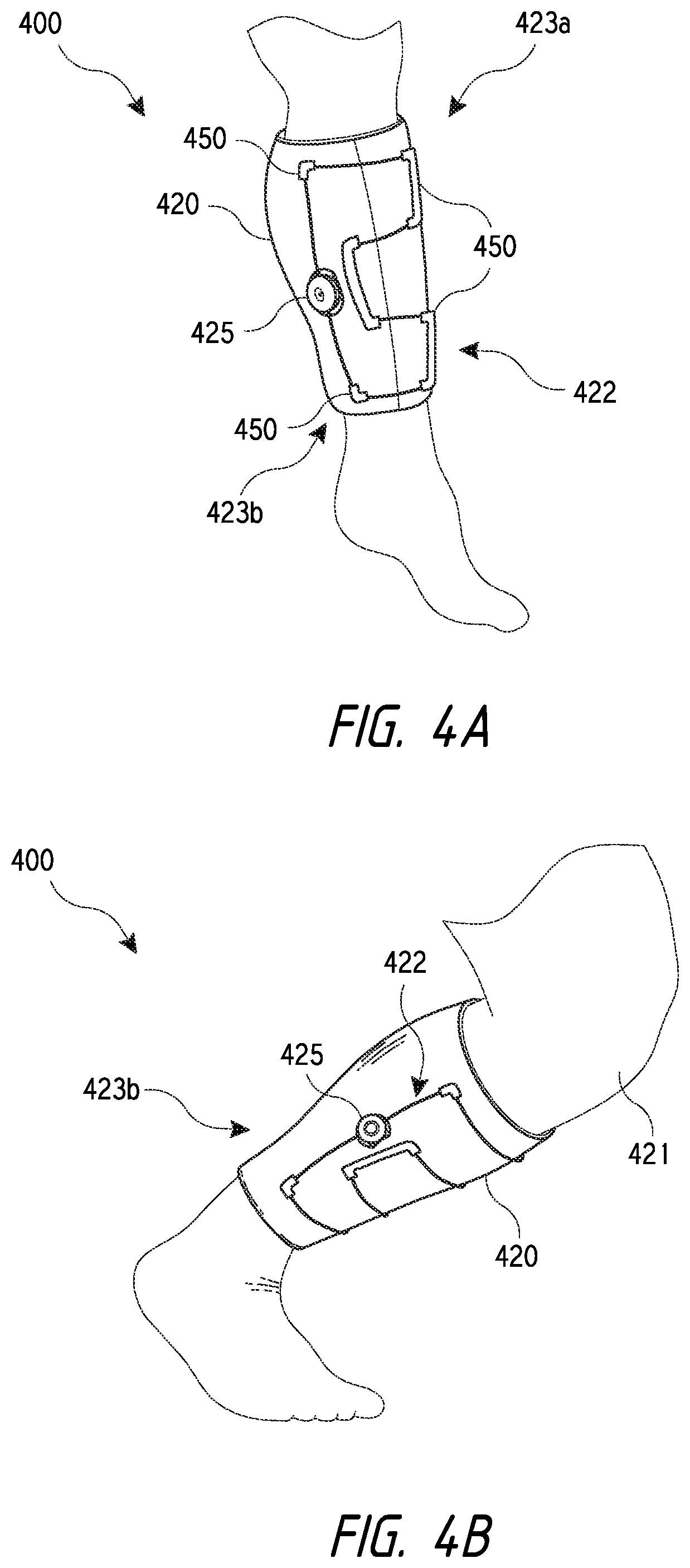
Referring now to FIGS. 4A-C, another example brace 400 is shown in accordance with the present disclosure. One advantage of using the brace 400, which is also applicable to other braces of the present disclosure, is the increased ability of the brace 400 to fit a conical shape or an adjusting shape of a limb, such as a leg 421, arm, or any other body part. The ability of the brace 400 to fit a conical shape is provided by a closure system 422. As the brace 400 is fit about the leg 421, for example, and lace 423 is tensioned or wound via reel mechanism 425, an upper portion 423a of the brace 400 contacts the leg 421 (i.e., conical-shaped object). As the lace 423 is wound, the lace 423 adjusts until a lower portion 423b of brace 400 also contacts the leg 421. Additional winding of the lace 423 will result in an approximately equal tension throughout the lace 423, which provides a relative even pressure on the leg 421. As such, the brace 400 is well-fit to accommodate the conical shape of the leg 421.
Similarly, the brace 400 is able to adjust to changes in the shape of the leg 421 (or other body part), due to flexing and/or relaxing of muscle. For example, as the leg 421 is flexed and assumes a more cylindrical shape, the lace 423 is able to slide within, or relative to, guides 450 so that the lower portion 423b of the brace 420 opens or widens as the top portion 423a contracts or shrinks Conventional braces typically do not adjust in this manner and as such, when the leg 421 (or other body part) is flexed, such braces may typically be forced to move or migrate about the body, such as downward against the knee or ankle. In the embodiments described herein, because the lace 423 is able to slide relative to the brace 400 and the guides 450, and the brace 400 is able to adjust to changes in shape, the fit or hold of the brace 400 about a particular body part is increased and migration of the brace 400 is limited or eliminated.
As mentioned previously, the use of buckles, Velcro.RTM., or other similar mechanisms often require the user to use both hands in opening and/or closing of a typical brace. For example, to couple the male and female components of a buckle, the user is often required to grasp the female component with one hand while the male component is being inserted into the female component so as to ensure that the female component will stay relatively in place. Similarly, in closing Velcro.RTM. straps, the user often must thread a distal end of the strap through a d-ring or hook before tensioning the strap and folding it back on itself. The user often must hold the d-ring or hook while the strap is being threaded therethrough. Requiring the use of both hands is often inconvenient, frustrating, and/or annoying to the user, and potentially not an option for dexterity compromised or handicapped individuals. Likewise, donning and doffing the brace in this manner may be needlessly time consuming.
The use of buckles, Velcro.RTM., or other similar mechanisms also allows the brace to be uncoupled while tension is still applied by the lace winding system described above. For example, the user can use buckles or Velcro.RTM. straps to roughly fit the brace about the leg and then use the closure or tightening system described herein to fine tune the fit of the brace about the leg. Without releasing tension in the lace, the user may then unbuckle or unstrap the brace to take the brace off or adjust the brace. Upon refitting the brace about the leg, the user may again use the buckles or straps to roughly fit the brace on the leg and then fine tune the fit with the closure or tightening system. If tension is not released in the lace before each removal of the brace, however, the lace will be continually wound into the tightening mechanism (e.g., the spool of the reel mechanism) resulting in increasingly shorter amounts of lace for use and possible over storage of the lace within the tightening mechanism. Further, tightening of the brace may not be possible if too much of the lace is wound into the tightening mechanism.
As briefly described above, embodiments of the present disclosure integrate components of closure devices into a single component, mechanism, or device that provides various advantages over conventional devices, such as being easier to use, reducing component count, simplifying the brace, and the like. According to one embodiment, the components of the brace may be integrated with a coupling system or device that may include a "reel panel assembly" or "reel panel" or "panel" that allows the user to close and tension the brace (i.e., tighten and loosen the brace). The term "panel" or "reel panel" as used herein includes virtually any component that other components or pieces may be attached to. The panels described herein are often generally flat so that the panel may lay flat against the brace, but the panels are not limited to such configurations and, indeed, may be contoured into other shapes as desired. The panels also typically have a top surface that the integrated components, such as the reel mechanism, attach to or couple with. The panels and/or components coupled with or integrated thereto may be made of plastic, metal, fabric, and the like, or any combination thereof. Further, in some embodiments, the panels may be variable in length and/or include one or more modular or removable components.
Referring now to FIGS. 5A-H, various embodiments of a closure system or device are shown arranged and configured in a manner consistent with the present disclosure. FIGS. 5A-D and FIGS. 5G-H in particular illustrate a first closure device 502 that generally comprises a male component 504 and a female component 506, and FIGS. 5C-D illustrate a second closure device 508 that too generally comprises a male component 510 and a female component 512. Details associated with the configuration and coupling of respective components of one or more of the first and second closure device 502, 508 are described further below. Additional details associated with the configuration and coupling of one or more of the first and second closure device 502, 508 are provided in U.S. Nonprovisional patent application Ser. No. 14/071,432, filed 4 Nov. 2013, the entirety of which is hereby incorporated by reference.
Referring specifically to FIGS. 5A-B, a sequence is illustrated whereby the male component 504 of the first closure device 502 is coupled to or with the female component 506 of the first closure device 502. In this example, a tension member (hereinafter lace 514) is generally threaded to a lumen or passage 516 of the male component 504, and the female component 506 is generally coupled to an end 518 of a brace 520. Although not shown, the lace 514 is further generally coupled to another end of the brace 520. In use, a step-shaped flange or tab 522 of the male component 504 is brought into engagement with a complementary step-shaped recess 524 of the female component 506 to couple the male component 504 with the female component 506. During this process, the male component 504 may be pushed downward into the female component 506 so that a pair of tabs 526 of the male component 504 engage with a grooved post 528 (see also, FIG. 5D) of the female component 506. The tabs 526 may "snap" into engagement with the grooved post 528 to produce audible feedback during coupling of the components. The tabs 526 may also provide tactile feedback so that when coupling of the components has occurred, a user may be able to tactually recognize when coupling occurs.
Following initial coupling of the male component 504 with the female component 506, a dial or reel mechanism 530 of the male component 504 may be rotated or adjusted as desired to fine tune a tension applied to the lace 514. In this example, the lace 514 is wrapped to internal spool (not shown) of the male component 504, so that when the reel 530 is rotated, the ends of the brace 520 may be pulled together to tighten the brace 520 around a limb as desired. As the lace 514 is tensioned, the lace 514 may tend to pull the male component 504 from the female component 506 in opposing directions so that various internal surfaces of the male component 504 and the female component 506 are pressed or biased together, as discussed in further detail below in connection with at least FIG. 8B and FIG. 13. This may beneficially make it difficult to release or decouple the male component 504 from the female component 506 without releasing tension on the lace 514 using the reel mechanism 530. The arrangement of the components of the closure device 502 allow the above closure and tightening process to be performed with a single hand.
It is contemplated that the male and female components of the various closure devices of the present disclosure may be coupled to a particular brace in many different types of configuration or arrangements. For example, as shown in FIG. 5C, lace 514 is threaded to the male component 504 of the first closure device 502 and also to guide members 532 that are coupled to a first panel 534 of a brace 536. In this example, the female component 506 of the first closure device 502 is generally coupled to a second panel 538 of the brace 536. In some embodiments, the lace 514 may be formed of a single segment, that is, the lace 514 may be formed of a single piece of lacing having a particular length. In this embodiment, the lace 514 may be threaded from the reel mechanism of male component 504, around guides 532, and further around a guide (not numbered) positioned on male component 504 centrally of the two ends of lace 514. In other embodiments, the lace 514 may be formed of two segments, that is, lace 514 may be formed of a first piece 544 of lacing having a particular length and second piece 546 of lacing having a particular length. In this example, an end of first piece 544 may be fixedly coupled to the male component at termination 540, while an end of second piece 546 is fixedly coupled to the male component at termination 542.
To couple the brace about a limb or bodily segment, the tab 522 of the male component 504 may be brought into engagement with the recess 524 of the female component 506 to couple the male component 504 with female component 506. The dial or reel mechanism 530 of the male component 504 may then be adjusted or rotated in a clockwise direction, for example, as desired to apply tension to the lace 514 to pull together the first panel 534 and the second panel 538 and tighten the brace 536 by fine adjustment. The reel mechanism 530 may also be adjusted or rotated in a counterclockwise direction for example as desired to release tension to the lace 514 to allow the brace 536 to loosen, or a knob of the reel mechanism 530 may be moved axially upward to release tension on the lace. In other embodiments, a button, lever, or other tension release mechanism may be used to release tension on the lace.
In the example of FIG. 5C, the lace 514 is threaded to a pair of guide members 532 that are coupled to the first panel 534 and are separated by a particular distance. This may enable the first panel 534 to be pulled evenly across its width when under tension by the lace 514. Other embodiments are however possible. For example, as shown in FIG. 5D, lace 514 is threaded to the male component 504 of the first closure device 502 and also to a single guide member 554 that is generally coupled to a first extension member or strap 556 of a brace 558. In this example, the female component 506 of the first closure device 502 is generally coupled to a second extension member or strap 560 of the brace 558 or to an edge of the brace 558. Still other embodiments are possible.
As mentioned above, FIGS. 5E-F illustrate a second closure device 508 that generally comprises a male component 510 and a female component 512. In FIG. 5E, lace 562 is generally threaded to a lumen or passage 564 of the male component 510, and the female component 512 is generally coupled to an end of a brace 566 (see also, FIG. 5F). The lace 562 is also coupled with a first strap 568 that is arranged in an over-and-back configuration between a first d-ring or hook 570, that is coupled with the male component 510, and a second d-ring or hook 572. A second strap 574 is also coupled to the second d-ring 572 and in turn is coupled with the brace 566. In general, the first strap 568 and the second strap 574 together may allow for gross tightening/loosening adjustments of the brace 566, whereas a dial or reel mechanism 576 of the male component 510 may allow for fine tightening/loosening adjustments. In FIG. 5F, in contrast, a distal end of the lace 562 may pass through and/or around a guide member 578 that is coupled with the brace 566, and a floating or mid-point guide 580 may be positioned between the male component 510 and the guide member 578. In this example, the lace 562 may be inserted through channels of the floating guide 580 for lace management purposes, to keep lace aligned about a desired lace path, and/or prevent the lace 562 from having direct contact with skin, which may be uncomfortable for an individual when the lace 562 is under tension. Still other lacing arrangements are possible.
FIGS. 5G-H illustrate the first closure device 502 whereby the male component 504 is generally coupled to a first strap 582 of a brace 584, and the female component 506 is generally coupled to a second strap 586 of the brace 584. In this example, a single guide member 588 is positioned to an end of the second strap 586 opposite the female component 506, and the male component 504 is coupled with lace 590 that in turn is threaded to the guide member 588. A slip sleeve 592 covers and protects the majority of the length of the lace 590 and at least the second strap 586, and also the guide member 588. Such an implementation may beneficially prevent lace 590 and/or other elements or features as shown in FIGS. 5G-H from having direct contact with skin, which may be uncomfortable for an individual when the lace 590 is tensioned. The sleeve 592 also hides the various components of the system from view. In some embodiments, the sleeve 592 may be coupled directly with an end of the male component 504 instead of, or in addition to, the first strap 582.
It will be appreciated that in such embodiments as described in connection with FIGS. 5A-H an individual may be able to easily don/doff a brace and tighten the brace with one hand. For example, an individual may easily place a brace that includes first closure device 502 over a leg or other body part, grasp the male component 504 with a single hand, pull the male component 504 over the leg or body part with the same hand, couple the male component 504 with the female component 506 by inserting the stepped protrusion or tab 522 of the male component 504 into the recess 524 of the female component 506, and subsequently tension the lace 514 by rotating the reel 530. In this manner, the closure devices of the present disclosure may be significantly easier and quicker to use than other closure systems.
Referring now to FIGS. 6A-D, additional closure device embodiments that may be used to close as well as tighten or loosen a brace are shown. For example, FIG. 6A illustrates a brace 602 whereby a lace 604 is threaded to guide members 606 generally coupled to a first end 608 of the brace 602, and also to a reel panel 610 at both a reel mechanism 622 via a reel channel 612 and a peripheral guide 614 positioned in front of the reel mechanism 622 and configured to guide the lace 604 between two lace segments. In use, a bottom side 616 of the reel panel 610 may be coupled to a Velcro.RTM. surface 618 generally formed to a second end 620 of the brace 602 to close the brace 602, apply tension to the lace 604, and secure the brace 602 to a limb (not shown) by gross adjustment. The reel mechanism 622 coupled to the reel panel 610 may then be rotated or adjusted to apply or release tension to the lace 604 by winding or unwinding the lace 604 to an internal spool (not shown) of the reel mechanism 622, to further tighten or loosen the brace 602 by fine adjustment. Similar to the above-described embodiments, it will be appreciated that an individual may be able to easily don/doff the brace 602 with one hand. Many other embodiments are possible.
FIG. 6B illustrates a brace 624 whereby lace 626 is threaded to guide members 628 generally coupled to a first end 630 of the brace 624, and also to a reel panel 632 at both a reel mechanism 646 via a reel channel 634 and a peripheral guide 636 positioned in front of the reel mechanism 646 and configured to guide the lace 626 between two lace segments. In this example, however, the peripheral guide 636 is formed by creating a lumen or channel between two a fabric materials 638 via a particular cross-stitch pattern 640. Additionally, one or more hooks 642 of the reel panel 632 may be coupled to a rod 644 that is attached to a second end 648 of the brace 602 to close the brace 624, apply tension to the lace 626, and secure the brace 624 to a limb by gross adjustment. The reel mechanism 646 coupled to the reel panel 632 may then be rotated or adjusted to apply or release tension to the lace 626 by winding or unwinding the lace 626 about an internal spool, to further tighten or loosen the brace 624 by fine adjustment. In coupling the hooks 642 about rod 644, the panel 632 is typically pulled in a first direction to pull the hooks 642 beyond the rod 644, and then retracted in a second direction to couple the hooks and rod. The other embodiments described herein, and in particular the male and female coupling components, do not require motion in opposite directions to couple or attach components of the reel panel.
In another example, FIG. 6C illustrates a brace 650 whereby lace 652 is threaded to guide members 654 generally coupled to a first end 656 of the brace 650, and also to a reel panel 658 at both a reel mechanism 670 via a reel channel 672 and a peripheral guide 674 positioned in front of the reel mechanism 670 and configured to guide the lace 652 between two lace segments. The reel panel 658 includes two tab members 676 or male components as described herein. In use, each tab member 676 of the reel panel 658 may be inserted within a complementary recess aperture 678 of a particular female component 680 coupled to, or formed within, a second end 682 of the brace 650, to close the brace 650, apply tension to the lace 652, and secure the brace 650 to a limb by gross adjustment. The reel mechanism 670 may then be rotated or adjusted to apply or release tension to the lace 652 by winding or unwinding the lace 652 to an internal spool, to further tighten or loosen the brace 650 by fine adjustment.
In this example, each tab member 676 of the reel panel 658 and each female component 680 coupled to a second end 682 of the brace 650 are substantially similar to like components discussed above in connection with the first closure device 502. Accordingly, the reel panel 658 may be pushed downward during this process so that snap tabs 526 and an associated aperture 527 (see also, FIG. 6M-O) engage with a grooved post 528 (see also, FIG. 5D or FIG. 8A) of each female component 680 to provide audio and/or tactile feedback to a user. Additionally, as shown in FIG. 6C, strips 684 formed of a flexible and/or elastic material, mesh, or the like, may be coupled to both the reel panel 658 and to the first end 656 of the brace 650 to prevent the lace 652 from having direct contact with skin, which may be uncomfortable for an individual when the lace 652 is under tension.
In still another example, FIG. 6D illustrates a brace 684 whereby lace 686 is threaded to guide members 688 and also to a reel panel 690 at both a reel mechanism 692 via a reel channel 694 and guide segments 696, 698, and a peripheral guide segment 700. In this example, each tab member 702 generally coupled to the reel panel 690 and each female component 704 generally coupled to a first end 706 of the brace 684 are substantially similar to like components discussed above in connection with the first closure device 502. The guide members 688 however are coupled to a particular one of elastic extension members or straps 710, which in turn are generally coupled to a second end 712 of the brace 684 at a particular ring 714. In use, length of the straps 710 protruding from each ring 714 may be adjusted as desired, and both gross and fine-closure adjustment may be performed in a manner similar to that described above by virtue of coupling each tab member 702 with a particular female component 704 and adjusting tension applied to the lace 686 using the reel 692.
As briefly mentioned above, the closure devices and/or reel panels of the present disclosure may be variable in length and/or include one or more modular or removable components. Example panels of variable length are shown in FIGS. 6E-J, and an example panel that includes one or more modular or removable components is shown in FIGS. 6K-L. FIGS. 6E-J specifically show multiple views of the reel panel 658 of FIG. 6C, excluding the reel mechanism 670 and internal spool, where FIGS. 6E-G in particular show multiple views of a first embodiment of the reel panel 658, and FIGS. 6H-J show multiple views of a second embodiment of the reel panel 658. The first embodiment of the reel panel 658 differs from the second embodiment of the reel panel 658 primarily in that the second embodiment exhibits more of an elongated shape. Among other things, the second embodiment may, due to an exaggerated shape or profile, distribute load imparted by tensioned lacing across a greater area than that achievable by the first embodiment of the reel panel 658. This may lend the second embodiment of the reel panel 658 to be more suitable for higher tension systems that might use heavier lacing, etc., whereas the first embodiment of the reel panel 658 may be more suitable for lower tension systems. Each of FIGS. 6E-J though illustrate similar features that enable tensioning and loosing of lace threaded to the reel panel 658.
For example, each of FIG. 6E and FIG. 6H show a housing 716 that includes housing teeth 718 and a post 720. The housing teeth 718 engage with corresponding teeth of a pawl disc (not shown) that may be removably coupled with or integrated into the reel mechanism 670. A spool (not shown) may be positioned within the housing 716 axially below the reel mechanism 670 and/or pawl disc. The spool may include a central aperture through which the post or boss 720 is inserted. The spool may include a channel around which the lace is wound. The spool may rotate around the post 720 as the lace is wound around the spool's channel. Similar features are discussed in further detail below in connection with FIG. 10. Also shown in each of FIG. 6E and FIG. 6H is the reel channel 672 and peripheral guide 674 of the reel panel 658, both of which enable threading of lace to the reel panel 658 and/or to different lace segments that span a gap of the brace. FIG. 6F in contrast illustrates in partial cross-section various internal surfaces of the reel channel 672 and peripheral guide 674 of the reel panel 658. Additionally, FIG. 6G and FIG. 6I show a side view and a front view, respectively, of the reel panel 658 including at least one of the tab members 676 and at least one of the snap tabs 526 as discussed above. FIG. 6G further shows curvature of the reel panel 658 when unloaded. It is contemplated that the at-rest curvature of the reel panel 658 may be defined as desired.
Referring now to FIGS. 6K-L, multiple views of an example reel panel 722 that includes an example modular or removable component 724 is shown. In general, the reel panel 722 may correspond substantially to any particular reel panel as discussed within the context of the present disclosure, such as the reel panel 658 as discussed above in connection with at least FIGS. 6E-J. Further, the removable component 724 may correspond substantially to any particular reel or a reel assembly as discussed within the context of the present disclosure, such as the reel mechanism 670 as discussed above in connection with at least FIG. 6C. As alluded to, however, the component 724 is removable and may be rigidly coupled, and then decoupled, to the reel panel 722 as desired.
For example, when initially positioned thereto, fastener apertures 726 of the removable component 724 may be positioned to hollow fastener posts 728 of the reel panel 722 and, as shown in the cross-section of FIG. 6L, a spring-loaded tab 730 of the reel panel 722 may engage with one or more surfaces of the removable component 724 so that the component 724 is snugly fit to the reel panel 722. Fasteners, such as screws, rivets, and the like for example, may then be positioned to the hollow fastener posts 728 of the reel panel 722 and through the fastener apertures 726 of the component 724 to rigidly couple the removable component 724 to the reel panel 722.
Referring now to FIGS. 6M-O, multiple views of the male component 504, excluding the reel mechanism 530 and internal spool, of the first closure device 502 as discussed above in connection with at least FIGS. 5A-B are shown. In general, the male component 504 of the first closure device 502 is substantially different than the male component 510 of the second closure device 508 as discussed above in connection with at least FIGS. 5E-F. This is because the step-shaped flange or tab 522 of the male component 504 of the first closure device 502 extends or protrudes far less from the housing 716 of the male component 504, when compared to like features of the male component 510 of the second closure device 508. This is achieved by incorporating the aperture 527 and snap tabs 526 of the male component 504 of the first closure device 502 into or within the housing 716 itself. In contrast, with reference to FIG. 5E for example, the snap tabs (not shown) and associated aperture 575 of the male component 510 of the second closure device 508 are incorporated into or on the step-shaped flange or tab 577 of the male component 510 of the second closure device 508. Such an implementation may be beneficial and/or advantageous in many respects. For example, the distance 579 as shown in FIG. 6O of which the tab 522 of the male component 504 of the first closure device 502 extends or protrudes from the housing 716 may be at least about 50% less than the distance 581 of like components of the second closure device 508 as shown in FIG. 5E.
Referring now to FIGS. 8A-B, multiple views of the male component 504, excluding the reel mechanism 530 and internal spool components, of the first closure device 502 coupled to the female component 506 of the first closure device 502 are shown. In this example, the coupling member or tab 522 (see also, FIGS. 6M-O) of the male component 504 is mated with a coupling recess 524 (see also, FIG. 5D) of the female component 506 to couple or mate the two components. In some embodiments, the coupling member or tab 522 is a stepped protrusion that is positioned at a distal end of a main body of male component 504. As shown in FIG. 8B, the stepped protrusion or tab 522 includes a tab 522a that extends approximately orthogonally downward from the main body of male component 504. A flange 522b extends approximately orthogonally from a distal end of the tab 522a such that the coupling member or tab 522 has a generally L-shaped or Z-shaped profile. The flange 522b has a relatively planar top surface that is offset from a relatively bottom surface 523 (see also, FIG. 5A) of the main body of male component 504. The term "relatively planar surface" as used herein may indicate that the surface is generally flat, but may include surfaces that are slightly curved and/or include other surface irregularities. The tab 522a and the flange 522b may collectively be referred to stepped protrusion or tab 522.
As also shown in FIG. 8B, the coupling recess 524 of the female component 506 includes a recessed portion 525 that is positioned immediately adjacent the coupling recess 524. The recessed portion 525 is typically a recess within a bottom portion of the main body of female component 506. In coupling the male component 504 and the female component 506, the stepped protrusion or tab 522 is insertable within the coupling aperture 524 such that the relatively planar top surface of the flange 522b is positioned immediately adjacent and under the recessed portion 525 of the female component 506. When the components are coupled together, a proximal or rear surface of the tab 522 engages with a lip or distal surface 527 of the coupling recess 524. Engagement of the rear surface of the tab 522 and the lip 527 of the coupling recess 524 maintains a coupled engagement of the male and female components 504, 506 when tension is applied between the components, such as when a tension member (e.g., lace or strap) is tensioned via a reel mechanism and the like. FIG. 8A-B also illustrate the grooved post 528 of the female component 506 engaged with the tabs 526 of the male component 504. The coupled components have a shorter overall length and/or profile due to the incorporation of the aperture 527 and snap tabs 526 within the housing of the male component 504. The smaller profile and/or length of the coupled components is advantageous in that the components occupy a smaller space on the brace and/or do not press downward against the user's body when the lace is tensioned. The small and compact design of the device also reduces contact of the device with objects as the user wears the brace.
Referring now to FIG. 9, a side view of the male component 504, including the reel mechanism 530 and internal spool components, of the first closure device 502 is shown whereby a stitching flange 529 of the male component 504 is positioned relative to the lumen or passage 516 of the male component 504, so that when fabric 531 or other material is stitched to the stitching flange 529 a channel 533 containing lacing 535 is orientated approximately parallel or in-line with the lumen or passage 516. The channel 533 may be an internal channel of sleeve 592 previously described, which is designed to cover and/or hide the lace 535 and/or other components.
The stitching flange 529 is positioned so as to be axially offset from a bottom surface of the male component 504. In some embodiments, the stitching flange 529 may be offset between about 1 and 5 mm, and more commonly between about 1 and 2 mm, from the bottom surface of the male component 504 to align the channel 533 with the passage 516. In a specific embodiment, the stitching flange 529 may be offset between about 1.3 and 1.5 mm from the bottom surface of the male component 504. Such an implementation or feature may be beneficial and/or advantageous in many respects. For example, friction or other degrading interactions between the lacing 535 and the fabric 531 may be minimized to prevent premature degradation of the lacing 535. The axially offset stitching flange 529 also allows the stitching flange 529 to be inserted between two layers of the fabric 531 as well. The stitching flange 529 may be coupled with fabric 531 via stitching, adhesive bonding, RF welding, and the like.
Referring now to FIGS. 10A-D, multiple views of an alternative embodiment of the male component 504 of the first closure device 102 are shown. In particular, the male component 504 is formed to exhibit a screw boss 1002 that is angularly offset from the tab 522 by an angle .theta. such that the screw boss 1002 is generally positioned on a side of the component 504, typically closure to the stitching flange. Positioning the screw boss 1002 on the side of the component 504 in this manner may maintain a minimized distance that the tab 522 and stitching flange extends or protrudes from the housing 716 of the male component 504 for reasons similar to those discussed above in connection with at least FIGS. 6M-O. For example, positioning the screw boss 1002 so as to be radially in line with either the tab 522 or stitching flange would require that the tab 522 or stitching flange extend radially farther from the housing 716, which increases the overall profile and/or length of the male component 504. In some embodiments, the angle .theta. may be between about 90 and 130 degrees, although an angle .theta. of between about 110 and 125 degrees is more common. In a specific embodiment, the angle .theta. is between about 115 and 120 degrees, which has been found to optimally position the screw boss 1002 away from the front edge and tab 522 and toward the rear-side edge of the male component 504 adjacent the lace ports or channels. The angle .theta. of 115 to 120 degrees also positions the screw boss 1002 from projecting directly out of the edge of the male component 504, which positioning would greatly increase the width of the component.
A security ring 1004 may be fastened to the male component 104 using a fastener 1006 to prevent unintended or unauthorized rotation of the reel mechanism 530 of the male component 504 to loosen or tighten a lace that is coupled thereto. Such an implementation or feature may be beneficial and/or advantageous in many respects. For example, a brace comprising the male component 504 of the first closure device 102 as shown in FIGS. 10A-D may be fitted to a limb of a minor child, for example, who may have the tendency to play with the reel mechanism 530 without understanding the possible negative implications of doing so. The security ring 1004 however when coupled to the male component 504 may prevent the minor child from doing so. In other embodiments, the reel mechanism 530 may be keyed (i.e., hexagonally shaped and the like) and the s
References
D00000
D00001
D00002
D00003
D00004
D00005
D00006
D00007
D00008
D00009
D00010
D00011
D00012

D00013

D00014

D00015
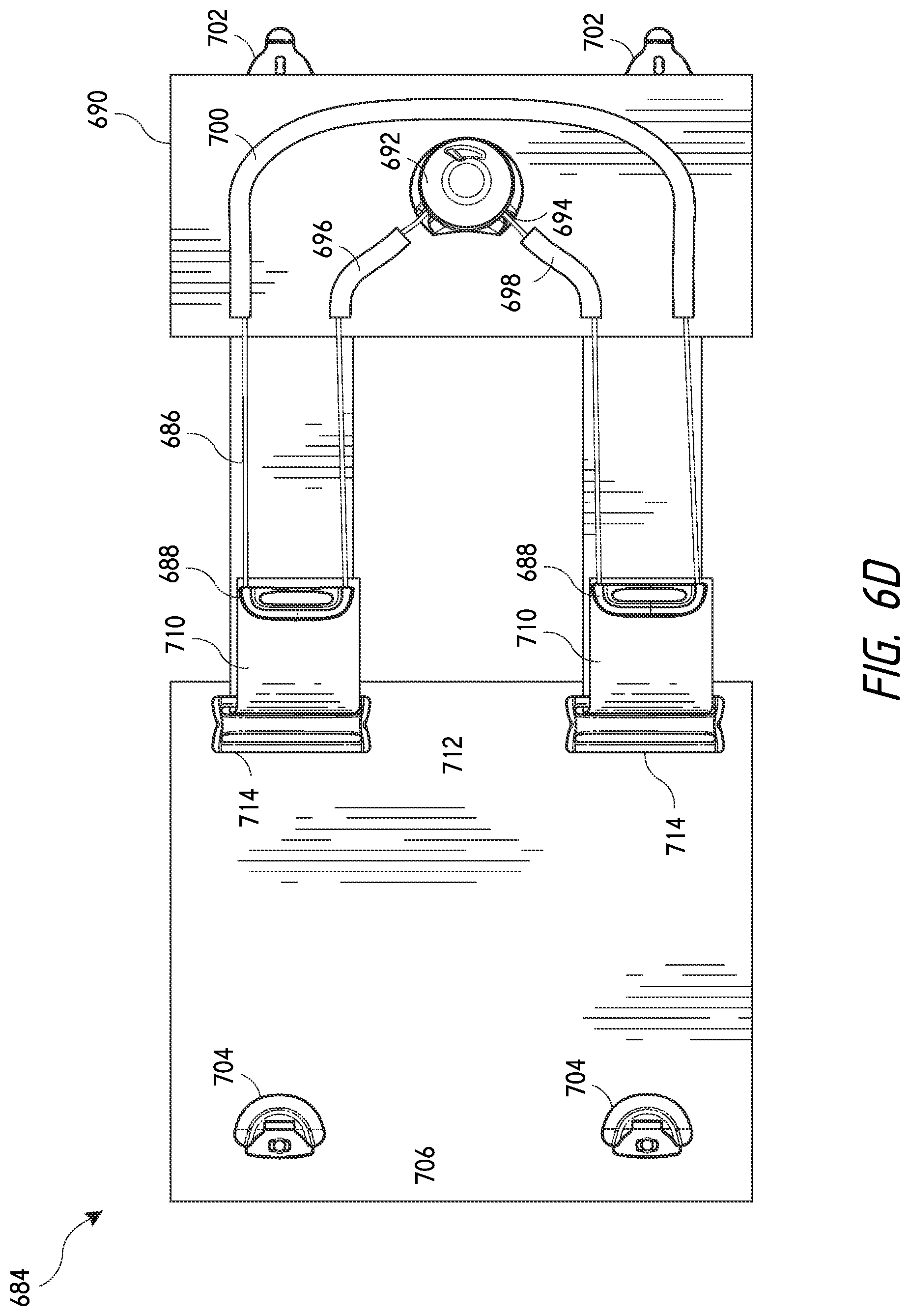
D00016

D00017

D00018

D00019

D00020

D00021

D00022

D00023

D00024

D00025

D00026

D00027

D00028
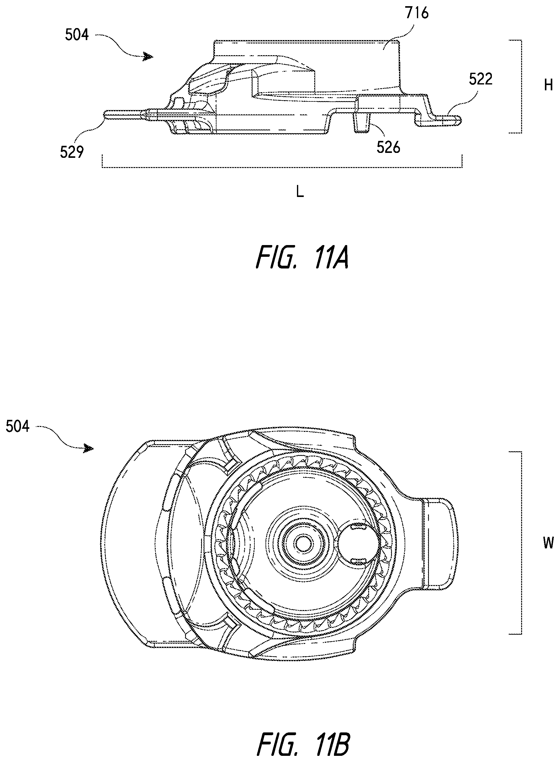
D00029

D00030

D00031
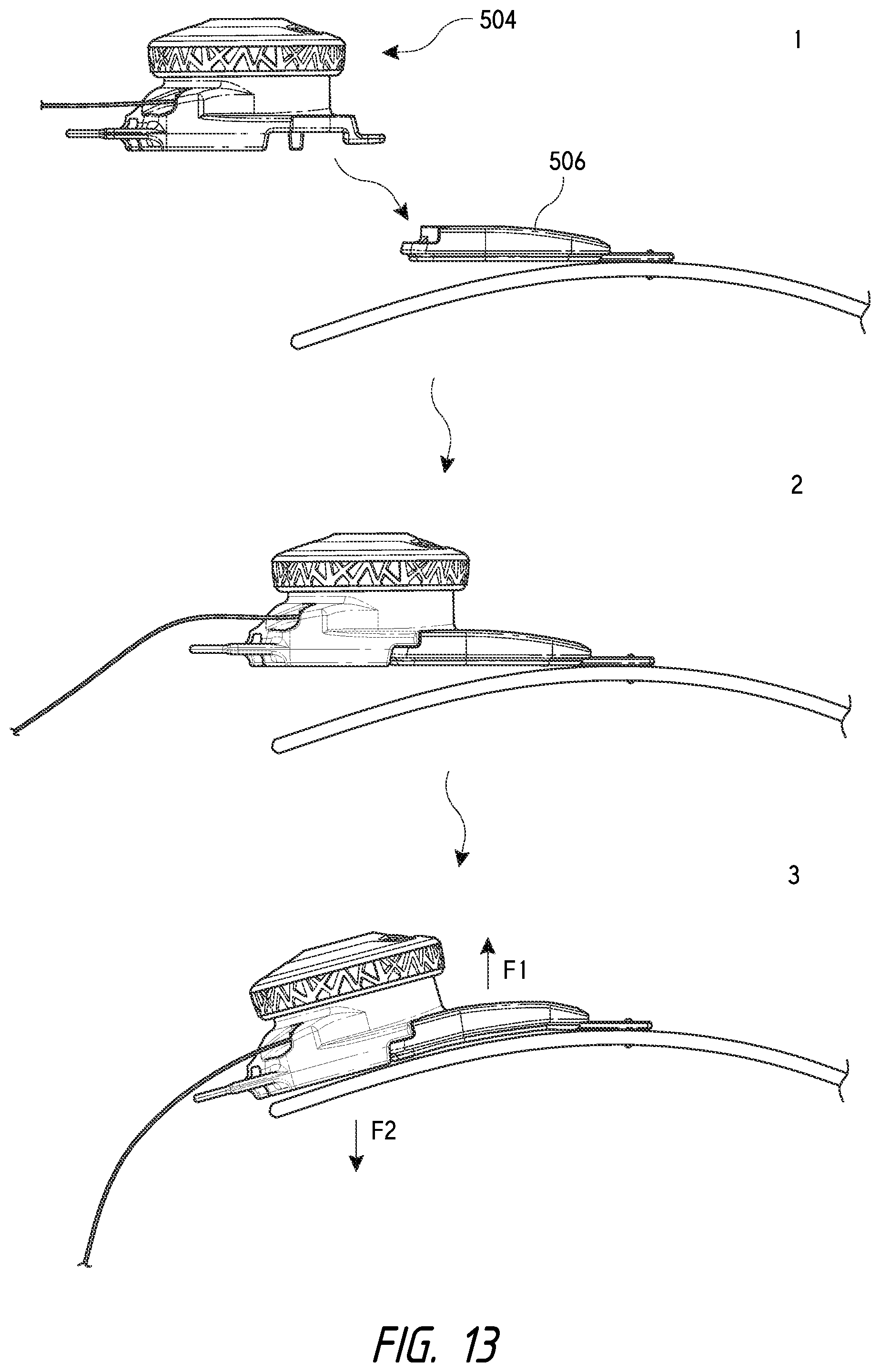
D00032

D00033

XML
uspto.report is an independent third-party trademark research tool that is not affiliated, endorsed, or sponsored by the United States Patent and Trademark Office (USPTO) or any other governmental organization. The information provided by uspto.report is based on publicly available data at the time of writing and is intended for informational purposes only.
While we strive to provide accurate and up-to-date information, we do not guarantee the accuracy, completeness, reliability, or suitability of the information displayed on this site. The use of this site is at your own risk. Any reliance you place on such information is therefore strictly at your own risk.
All official trademark data, including owner information, should be verified by visiting the official USPTO website at www.uspto.gov. This site is not intended to replace professional legal advice and should not be used as a substitute for consulting with a legal professional who is knowledgeable about trademark law.