Two-stage method for treating calcified lesions within the wall of a blood vessel
Adams , et al.
U.S. patent number 10,702,293 [Application Number 16/544,516] was granted by the patent office on 2020-07-07 for two-stage method for treating calcified lesions within the wall of a blood vessel. This patent grant is currently assigned to Shockwave Medical, Inc.. The grantee listed for this patent is Shockwave Medical, Inc.. Invention is credited to John M. Adams, Clifton A. Alferness, Daniel Hawkins.
| United States Patent | 10,702,293 |
| Adams , et al. | July 7, 2020 |
Two-stage method for treating calcified lesions within the wall of a blood vessel
Abstract
A method is disclosed for treating calcified lesions within a wall of a blood vessel. The first step includes breaking apart a calcified lesion using a plurality of shockwaves generated in an angioplasty balloon of an angioplasty catheter device. The angioplasty balloon is dilated via a fluid to a first extent to fit against at least a portion of the wall of the blood vessel. A plurality of electrical pulses are delivered to a pair of electrodes disposed within the fluid inside the balloon. The electrical pulses have an amplitude sufficient to create plasma arcs in the fluid to generate shockwaves that are conducted through the fluid and through the balloon to the blood vessel, to crack the calcified lesion. After breaking apart the calcified lesion, the angioplasty balloon is allowed to further expand to a second extent greater than the first extent, thereby expanding an opening in the blood vessel.
| Inventors: | Adams; John M. (Snohomish, WA), Hawkins; Daniel (Santa Clara, CA), Alferness; Clifton A. (Olalla, WA) | ||||||||||
|---|---|---|---|---|---|---|---|---|---|---|---|
| Applicant: |
|
||||||||||
| Assignee: | Shockwave Medical, Inc. (Santa
Clara, CA) |
||||||||||
| Family ID: | 68694926 | ||||||||||
| Appl. No.: | 16/544,516 | ||||||||||
| Filed: | August 19, 2019 |
Prior Publication Data
| Document Identifier | Publication Date | |
|---|---|---|
| US 20190365400 A1 | Dec 5, 2019 | |
Related U.S. Patent Documents
| Application Number | Filing Date | Patent Number | Issue Date | ||
|---|---|---|---|---|---|
| 16028225 | Jul 5, 2018 | ||||
| 14660539 | Aug 7, 2018 | 10039561 | |||
| 13646570 | Apr 21, 2015 | 9011462 | |||
| 12482995 | Feb 17, 2015 | 8956371 | |||
| 61061170 | Jun 13, 2008 | ||||
| Current U.S. Class: | 1/1 |
| Current CPC Class: | A61B 17/2202 (20130101); A61B 17/22029 (20130101); A61B 17/22022 (20130101); A61B 2017/22001 (20130101); A61B 2017/22058 (20130101); A61B 2017/22062 (20130101); A61B 2017/22021 (20130101); A61B 2017/22038 (20130101); A61B 2017/22025 (20130101); A61B 2017/22061 (20130101); A61B 17/320725 (20130101); A61B 17/2251 (20130101); A61B 2017/22024 (20130101) |
| Current International Class: | A61B 17/22 (20060101); A61B 17/225 (20060101); A61B 17/3207 (20060101) |
| Field of Search: | ;606/127,128,159,194 |
References Cited [Referenced By]
U.S. Patent Documents
| 3413976 | December 1968 | Roze |
| 3785382 | January 1974 | Schmidt-Kloiber et al. |
| 3902499 | September 1975 | Shene |
| 4027674 | June 1977 | Tessler et al. |
| 4030505 | June 1977 | Tessler |
| 4445509 | May 1984 | Auth |
| 4662126 | May 1987 | Malcolm |
| 4671254 | June 1987 | Fair |
| 4685458 | August 1987 | Leckrone |
| 4809682 | March 1989 | Forssmann et al. |
| 4813934 | March 1989 | Engelson et al. |
| 4878495 | November 1989 | Grayzel |
| 4900303 | February 1990 | Lemelson |
| 4990134 | February 1991 | Auth |
| 4994032 | February 1991 | Sugiyama et al. |
| 5009232 | April 1991 | Hassler et al. |
| 5046503 | September 1991 | Schneiderman |
| 5047685 | September 1991 | Nowacki |
| 5057103 | October 1991 | Davis |
| 5057106 | October 1991 | Kasevich et al. |
| 5061240 | October 1991 | Cherian |
| 5078717 | January 1992 | Parins et al. |
| 5103804 | April 1992 | Abele et al. |
| 5116227 | May 1992 | Levy |
| 5152767 | October 1992 | Sypal et al. |
| 5152768 | October 1992 | Bhatta |
| 5154722 | October 1992 | Filip et al. |
| 5176675 | January 1993 | Watson et al. |
| 5195508 | March 1993 | Muller et al. |
| 5245988 | September 1993 | Einars et al. |
| 5246447 | September 1993 | Rosen et al. |
| 5281231 | January 1994 | Rosen et al. |
| 5295958 | March 1994 | Shturman |
| 5321715 | June 1994 | Trost |
| 5324255 | June 1994 | Passafaro et al. |
| 5336234 | August 1994 | Vigil et al. |
| 5362309 | November 1994 | Carter |
| 5364393 | November 1994 | Auth et al. |
| 5368591 | November 1994 | Lennox et al. |
| 5395335 | March 1995 | Jang |
| 5417208 | May 1995 | Winkler |
| 5425735 | June 1995 | Rosen et al. |
| 5472406 | December 1995 | de la Torre et al. |
| 5582578 | December 1996 | Zhong et al. |
| 5584843 | December 1996 | Wulfman et al. |
| 5603731 | February 1997 | Whitney |
| 5609606 | March 1997 | O'Boyle |
| 5662590 | September 1997 | de la Torre et al. |
| 5709676 | January 1998 | Alt |
| 5846218 | December 1998 | Brisken et al. |
| 5891089 | April 1999 | Katz et al. |
| 5931805 | August 1999 | Brisken |
| 6007530 | December 1999 | Dornhofer et al. |
| 6033371 | March 2000 | Torre et al. |
| 6056722 | May 2000 | Jayaraman |
| 6080119 | June 2000 | Schwarze et al. |
| 6083232 | July 2000 | Cox |
| 6113560 | September 2000 | Simnacher |
| 6132444 | October 2000 | Shturman et al. |
| 6186963 | February 2001 | Schwarze et al. |
| 6210408 | April 2001 | Chandrasekaran et al. |
| 6217531 | April 2001 | Reitmajer |
| 6267747 | July 2001 | Samson et al. |
| 6277138 | August 2001 | Levinson et al. |
| 6287272 | September 2001 | Brisken et al. |
| 6352535 | March 2002 | Lewis et al. |
| 6364894 | April 2002 | Healy |
| 6367203 | April 2002 | Graham et al. |
| 6371971 | April 2002 | Tsugita et al. |
| 6398792 | June 2002 | O'Connor |
| 6406486 | June 2002 | De La Torre et al. |
| 6494890 | December 2002 | Shturman et al. |
| 6514203 | February 2003 | Bukshpan |
| 6524251 | February 2003 | Rabiner et al. |
| 6589253 | July 2003 | Cornish et al. |
| 6607003 | August 2003 | Wilson |
| 6638246 | October 2003 | Naimark et al. |
| 6652547 | November 2003 | Rabiner |
| 6689089 | February 2004 | Tiedtke et al. |
| 6736784 | May 2004 | Menne et al. |
| 6740081 | May 2004 | Hilal |
| 6755821 | June 2004 | Fry |
| 6989009 | January 2006 | Lafontaine |
| 7241295 | July 2007 | Maguire |
| 7309324 | December 2007 | Hayes |
| 7505812 | March 2009 | Eggers et al. |
| 7569032 | August 2009 | Naimark et al. |
| 7618432 | November 2009 | Pedersen et al. |
| 7873404 | January 2011 | Patton |
| 7951111 | May 2011 | Drasler et al. |
| 8162859 | April 2012 | Schultheiss et al. |
| 8177801 | May 2012 | Kallok et al. |
| 8353923 | January 2013 | Shturman |
| 8556813 | October 2013 | Cioanta et al. |
| 8574247 | November 2013 | Adams et al. |
| 8728091 | May 2014 | Hakala et al. |
| 8747416 | June 2014 | Hakala et al. |
| 8888788 | November 2014 | Hakala et al. |
| 8956371 | February 2015 | Hawkins et al. |
| 8956374 | February 2015 | Hawkins |
| 9005216 | April 2015 | Hakala et al. |
| 9011462 | April 2015 | Adams et al. |
| 9011463 | April 2015 | Adams et al. |
| 9044618 | June 2015 | Hawkins et al. |
| 9044619 | June 2015 | Hawkins et al. |
| 9333000 | May 2016 | Hakala et al. |
| 9421025 | August 2016 | Hawkins et al. |
| 10039561 | August 2018 | Adams et al. |
| 10149690 | December 2018 | Hawkins et al. |
| 2001/0044596 | November 2001 | Jaafar |
| 2002/0045890 | April 2002 | Celliers et al. |
| 2002/0082553 | June 2002 | Duchamp |
| 2002/0177889 | November 2002 | Brisken et al. |
| 2003/0004434 | January 2003 | Greco et al. |
| 2003/0176873 | September 2003 | Chernenko et al. |
| 2003/0229370 | December 2003 | Miller |
| 2004/0044308 | March 2004 | Naimark et al. |
| 2004/0097963 | May 2004 | Seddon |
| 2004/0097996 | May 2004 | Rabiner et al. |
| 2004/0162508 | August 2004 | Uebelacker |
| 2004/0254570 | December 2004 | Hadjicostis et al. |
| 2005/0015953 | January 2005 | Keidar |
| 2005/0021013 | January 2005 | Visuri et al. |
| 2005/0059965 | March 2005 | Eberl et al. |
| 2005/0075662 | April 2005 | Pedersen et al. |
| 2005/0090888 | April 2005 | Hines et al. |
| 2005/0113722 | May 2005 | Schultheiss |
| 2005/0113822 | May 2005 | Fuimaono et al. |
| 2005/0171527 | August 2005 | Bhola |
| 2005/0228372 | October 2005 | Truckai et al. |
| 2005/0245866 | November 2005 | Azizi |
| 2005/0251131 | November 2005 | Lesh |
| 2006/0004286 | January 2006 | Chang et al. |
| 2006/0074484 | April 2006 | Huber |
| 2006/0184076 | August 2006 | Gill et al. |
| 2006/0190022 | August 2006 | Beyar et al. |
| 2007/0016112 | January 2007 | Schultheiss et al. |
| 2007/0088380 | April 2007 | Hirszowicz et al. |
| 2007/0129667 | June 2007 | Tiedtke et al. |
| 2007/0239082 | October 2007 | Schultheiss |
| 2007/0239253 | October 2007 | Jagger et al. |
| 2007/0244423 | October 2007 | Zumeris et al. |
| 2007/0255270 | November 2007 | Carney |
| 2007/0282301 | December 2007 | Segalescu et al. |
| 2007/0299481 | December 2007 | Syed et al. |
| 2008/0097251 | April 2008 | Babaev |
| 2008/0188913 | August 2008 | Stone et al. |
| 2009/0041833 | February 2009 | Bettinger et al. |
| 2009/0247945 | October 2009 | Levit et al. |
| 2009/0254114 | October 2009 | Hirszowicz et al. |
| 2009/0312768 | December 2009 | Hawkins |
| 2010/0016862 | January 2010 | Hawkins et al. |
| 2010/0036294 | February 2010 | Mantell |
| 2010/0094209 | April 2010 | Drasler et al. |
| 2010/0114020 | May 2010 | Hawkins et al. |
| 2010/0114065 | May 2010 | Hawkins et al. |
| 2010/0121322 | May 2010 | Swanson |
| 2010/0305565 | December 2010 | Truckai et al. |
| 2011/0034832 | February 2011 | Cioanta et al. |
| 2011/0118634 | May 2011 | Golan |
| 2011/0166570 | July 2011 | Hawkins et al. |
| 2011/0208185 | August 2011 | Diamant et al. |
| 2011/0295227 | December 2011 | Hawkins et al. |
| 2012/0071889 | March 2012 | Mantell et al. |
| 2012/0095461 | April 2012 | Herscher et al. |
| 2012/0203255 | August 2012 | Hawkins et al. |
| 2012/0221013 | August 2012 | Hawkins et al. |
| 2013/0030431 | January 2013 | Adams |
| 2013/0030447 | January 2013 | Adams |
| 2014/0005576 | January 2014 | Adams et al. |
| 2014/0039513 | February 2014 | Hakala et al. |
| 2014/0052145 | February 2014 | Adams et al. |
| 2014/0052147 | February 2014 | Hakala et al. |
| 2014/0074111 | March 2014 | Hakala et al. |
| 2014/0074113 | March 2014 | Hakala et al. |
| 2014/0243820 | August 2014 | Adams et al. |
| 2014/0243847 | August 2014 | Hakala et al. |
| 2014/0288570 | September 2014 | Adams |
| 2015/0073430 | March 2015 | Hakala et al. |
| 2015/0238208 | August 2015 | Adams et al. |
| 2015/0238209 | August 2015 | Hawkins et al. |
| 2015/0320432 | November 2015 | Adams |
| 2016/0151081 | June 2016 | Adams et al. |
| 2016/0183957 | June 2016 | Hakala et al. |
| 2016/0324534 | November 2016 | Hawkins et al. |
| 2018/0317946 | November 2018 | Adams et al. |
| 2019/0069916 | March 2019 | Hawkins et al. |
| 2009313507 | Nov 2014 | AU | |||
| 1269708 | Oct 2000 | CN | |||
| 101043914 | Sep 2007 | CN | |||
| 102057422 | May 2011 | CN | |||
| 102271748 | Dec 2011 | CN | |||
| 102765785 | Nov 2012 | CN | |||
| 3038445 | May 1982 | DE | |||
| 3038445 | May 1982 | DE | |||
| 0442199 | Aug 1991 | EP | |||
| 0571306 | Nov 1993 | EP | |||
| 0571306 | Nov 1993 | EP | |||
| 0623360 | Nov 1994 | EP | |||
| 2253884 | Nov 2010 | EP | |||
| 2362798 | Apr 2014 | EP | |||
| 60-191353 | Dec 1985 | JP | |||
| 62-99210 | Jun 1987 | JP | |||
| 62-275446 | Nov 1987 | JP | |||
| S62-275446 | Nov 1987 | JP | |||
| 3-63059 | Mar 1991 | JP | |||
| 6-125915 | May 1994 | JP | |||
| 7047135 | Feb 1995 | JP | |||
| 8-89511 | Apr 1996 | JP | |||
| 10-99444 | Apr 1998 | JP | |||
| 10-314177 | Dec 1998 | JP | |||
| 10-513379 | Dec 1998 | JP | |||
| 2002-538932 | Nov 2002 | JP | |||
| 2004-81374 | Mar 2004 | JP | |||
| 2004-357792 | Dec 2004 | JP | |||
| 2005-95410 | Apr 2005 | JP | |||
| 2005-515825 | Jun 2005 | JP | |||
| 2006-516465 | Jul 2006 | JP | |||
| 2007-532182 | Nov 2007 | JP | |||
| 2008-506447 | Mar 2008 | JP | |||
| 2011-513694 | Apr 2011 | JP | |||
| 2011-520248 | Jul 2011 | JP | |||
| 2011-524203 | Sep 2011 | JP | |||
| 2011-528963 | Dec 2011 | JP | |||
| 2012-505050 | Mar 2012 | JP | |||
| 2012-508042 | Apr 2012 | JP | |||
| 6029828 | Nov 2016 | JP | |||
| 6081510 | Feb 2017 | JP | |||
| 1996/024297 | Aug 1996 | WO | |||
| 1999/02096 | Jan 1999 | WO | |||
| 2004/069072 | Aug 2004 | WO | |||
| 2005/099594 | Oct 2005 | WO | |||
| 2006/006169 | Jan 2006 | WO | |||
| 2006/127158 | Nov 2006 | WO | |||
| 2007/088546 | Aug 2007 | WO | |||
| 2007/149905 | Dec 2007 | WO | |||
| 2009/121017 | Oct 2009 | WO | |||
| 2009/126544 | Oct 2009 | WO | |||
| 2009/152352 | Dec 2009 | WO | |||
| 2010/014515 | Feb 2010 | WO | |||
| 2010/054048 | May 2010 | WO | |||
| 2010/014515 | Aug 2010 | WO | |||
| 2010/054048 | Sep 2010 | WO | |||
| 2011/143468 | Nov 2011 | WO | |||
| 2012/025833 | Mar 2012 | WO | |||
Other References
|
Advisory Action received for U.S. Appl. No. 13/615,107, dated Nov. 6, 2015, 3 pages. cited by applicant . Advisory Action received for U.S. Appl. No. 12/482,995, dated Jun. 2, 2014, 3 pages. cited by applicant . Advisory Action received for U.S. Appl. No. 12/482,995, dated Sep. 29, 2011, 2 pages. cited by applicant . Advisory Action received for U.S. Appl. No. 12/581,295, dated Jul. 3, 2014, 3 pages. cited by applicant . Advisory Action received for U.S. Appl. No. 13/049,199, dated Jun. 7, 2012, 3 pages. cited by applicant . Advisory Action received for U.S. Appl. No. 13/267,383, dated Jan. 6, 2014, 4 pages. cited by applicant . Decision to Grant received for European Patent Application No. 09763640.1, dated Feb. 22, 2018, 2 pages. cited by applicant . Decision of Appeals Notice received for Japanese Patent Application No. 2011-534914, dated Oct. 17, 2016, 2 pages. cited by applicant . Decision to Grant received for European Patent Application No. 13756766.5, dated May 27, 2016, 2 pages. cited by applicant . Decision to Grant received for European Patent Application No. 09825393.3, dated Mar. 13, 2014, 2 pages. cited by applicant . Decision to Grant received for Japanese Patent Application No. 2011-513694, dated Oct. 7, 2014, 3 pages. cited by applicant . Extended European Search Report (includes Supplementary European Search Report and Search Opinion) received for European Patent Application No. 09763640.1, dated Oct. 10, 2013, 5 pages. cited by applicant . Extended European Search Report and Search Opinion received for European Patent Application No. 09825393.3, dated Feb. 28, 2013, 6 pages. cited by applicant . Extended European Search Report received for European Patent Application No. 13827971.6, dated Apr. 12, 2016, 8 pages. cited by applicant . Final Office Action received for U.S. Appl. No. 15/213,105, dated May 4, 2018, 8 pages. cited by applicant . Final Office Action received for U.S. Appl. No. 12/482,995, dated Jul. 22, 2011, 14 pages. cited by applicant . Final Office Action received for U.S. Appl. No. 12/611,997, dated Dec. 11, 2012, 9 pages. cited by applicant . Final Office Action received for U.S. Appl. No. 12/611,997, dated Nov. 10, 2011, 15 pages. cited by applicant . Final Office Action received for U.S. Appl. No. 13/049,199, dated Apr. 4, 2012, 10 pages. cited by applicant . Final Office Action received for U.S. Appl. No. 13/207,381, dated Nov. 2, 2012, 7 pages. cited by applicant . Final Office Action received for U.S. Appl. No. 14/271,342 dated Feb. 27, 2015, 7 pages. cited by applicant . Final Office Action received for U.S. Appl. No. 12/482,995, dated Feb. 20, 2014, 11 pages. cited by applicant . Final Office Action received for U.S. Appl. No. 12/581,295, dated Jun. 5, 2014, 14 pages. cited by applicant . Final Office Action received for U.S. Appl. No. 12/611,997, dated Oct. 24, 2013, 10 pages. cited by applicant . Final Office Action received for U.S. Appl. No. 13/049,199 dated Aug. 11, 2014, 8 pages. cited by applicant . Final Office Action received for U.S. Appl. No. 13/207,381, dated Nov. 7, 2013, 7 pages. cited by applicant . Final Office Action received for U.S. Appl. No. 13/267,383, dated May 28, 2015, 12 pages. cited by applicant . Final Office Action received for U.S. Appl. No. 13/267,383, dated Oct. 25, 2013, 8 pages. cited by applicant . Final Office Action received for U.S. Appl. No. 13/534,658, dated Aug. 23, 2016, 11 pages. cited by applicant . Final Office Action received for U.S. Appl. No. 13/615,107 dated Sep. 1, 2015, 9 pages. cited by applicant . Final Office Action received for U.S. Appl. No. 13/646,570, dated Dec. 23, 2014, 10 pages. cited by applicant . Final Office Action received for U.S. Appl. No. 14/229,735, dated Aug. 27, 2015, 7 pages. cited by applicant . Final Office Action received for U.S. Appl. No. 14/660,539, dated Aug. 3, 2017, 11 pages. cited by applicant . Intention to Grant received for European Patent Application No. 13756766.5, dated Jan. 8, 2016, 5 pages. cited by applicant . International Preliminary Report on Patentability received for PCT Patent Application No. PCT/US2009/047070, dated Dec. 23, 2010, 7 pages. cited by applicant . International Preliminary Report on Patentability received for PCT Patent Application No. PCT/US2009/063354, dated May 19, 2011, 6 pages. cited by applicant . International Preliminary Report on Patentability received for PCT Patent Application No. PCT/US2011/047070, dated Feb. 21, 2013, 7 pages. cited by applicant . International Preliminary Report on Patentability received for PCT Patent Application No. PCT/US2012/023172, dated Aug. 15, 2013, 6 pages. cited by applicant . International Preliminary Report on Patentability received for PCT Patent Application No. PCT/US2013/031805, dated Feb. 19, 2015, 11 pages. cited by applicant . International Preliminary Report on Patentability received for PCT Patent Application No. PCT/US2013/039987, dated Nov. 20, 2014, 11 pages. cited by applicant . International Preliminary Report on Patentability received for PCT Patent Application No. PCT/US2013/048277, dated Jan. 8, 2015, 9 pages. cited by applicant . International Preliminary Report on Patentability received for PCT Patent Application No. PCT/US2013/055431, dated Feb. 26, 2015, 7 pages. cited by applicant . International Preliminary Report on Patentability received for PCT Patent Application No. PCT/US2013/059533, dated Mar. 26, 2015, 10 pages. cited by applicant . International Search Report and Written Opinion received for PCT Patent Application No. PCT/US2013/031805, dated May 20, 2013, 13 pages. cited by applicant . International Search Report and Written Opinion received for PCT Patent Application No. PCT/US2013/039987, dated Sep. 23, 2013, 15 pages. cited by applicant . International Search Report and Written Opinion received for PCT Patent Application No. PCT/US2013/048277, dated Oct. 2, 2013, 14 pages. cited by applicant . International Search Report and Written Opinion received for PCT Patent Application No. PCT/US2013/055431, dated Nov. 12, 2013, 9 pages. cited by applicant . International Search Report and Written Opinion received for PCT Patent Application No. PCT/US2013/059533, dated Nov. 7, 2013, 14 pages. cited by applicant . International Search Report and Written Opinion received for PCT Patent Application No. PCT/US2015/029088, dated Jul. 16, 2015, 13 pages. cited by applicant . International Search Report received for PCT Patent Application No. PCT/US2009/047070, dated Jan. 19, 2010, 4 pages. cited by applicant . International Search Report received for PCT Patent Application No. PCT/US2009/063354, dated Jun. 11, 2010, 3 pages. cited by applicant . International Search Report received for PCT Patent Application No. PCT/US2012/023172, dated Sep. 28, 2012, 3 pages. cited by applicant . International Written Opinion received for PCT Patent Application No. PCT/US2009/063354, dated Jun. 11, 2010, 4 pages. cited by applicant . International Written Opinion received for PCT Patent Application No. PCT/US2011/047070, dated May 1, 2012, 5 pages. cited by applicant . Intention to Grant received for European Patent Application No. 09763640.1, dated Oct. 11, 2017, 8 pages. cited by applicant . Non-Final Office Action received for U.S. Appl. No. 15/213,105, dated Nov. 28, 2017, 7 pages. cited by applicant . Non-Final Office Action received for U.S. Appl. No. 12/482,995, dated Aug. 13, 2014, 10 pages. cited by applicant . Non-Final Office Action received for U.S. Appl. No. 12/482,995, dated Jul. 12, 2013, 11 pages. cited by applicant . Non-Final Office Action received for U.S. Appl. No. 12/611,997, dated Nov. 26, 2014, 8 pages. cited by applicant . Non-Final Office Action received for U.S. Appl. No. 13/207,381, dated Nov. 25, 2014, 5 pages. cited by applicant . Non-Final Office Action received for U.S. Appl. No. 13/465,264, dated Oct. 29, 2014, 13 pages. cited by applicant . Non-Final Office Action received for U.S. Appl. No. 13/646,570, dated Oct. 29, 2014, 10 pages. cited by applicant . Non-Final Office Action received for U.S. Appl. No. 14/079,463, dated Mar. 4, 2014, 9 pages. cited by applicant . Non-Final Office Action received for U.S. Appl. No. 12/482,995, dated Feb. 11, 2011, 27 pages. cited by applicant . Non-Final Office Action received for U.S. Appl. No. 12/611,997, dated Apr. 8, 2013, 9 pages. cited by applicant . Non-Final Office Action received for U.S. Appl. No. 12/611,997, dated Aug. 24, 2012, 11 pages. cited by applicant . Non-Final Office Action received for U.S. Appl. No. 12/611,997, dated Jun. 21, 2011, 13 pages. cited by applicant . Non-Final Office Action received for U.S. Appl. No. 13/049,199, dated Dec. 12, 2011, 10 pages. cited by applicant . Non-Final Office Action received for U.S. Appl. No. 13/207,381, dated Feb. 22, 2013, 7 pages. cited by applicant . Non-Final Office Action received for U.S. Appl. No. 13/207,381, dated Jun. 12, 2012, 6 pages. cited by applicant . Non-Final Office Action received for U.S. Appl. No. 13/534,658, dated Mar. 11, 2016, 12 pages. cited by applicant . Non-Final Office Action received for U.S. Appl. No. 14/218,858, dated Mar. 30, 2016, 13 pages. cited by applicant . Non-Final Office Action received for U.S. Appl. No. 14/515,130, dated Jan. 14, 2016, 16 pages. cited by applicant . Non-Final Office Action received for U.S. Appl. No. 12/501,619, dated Jan. 28, 2014, 10 pages. cited by applicant . Non-Final Office Action received for U.S. Appl. No. 12/581,295, dated Jan. 15, 2015, 14 pages. cited by applicant . Non-Final Office Action received for U.S. Appl. No. 12/581,295, dated Mar. 10, 2014, 11 pages. cited by applicant . Non-Final Office Action received for U.S. Appl. No. 12/611,997, dated Feb. 13, 2014, 9 pages. cited by applicant . Non-Final Office Action received for U.S. Appl. No. 13/049,199, dated Feb. 4, 2014, 8 pages. cited by applicant . Non-Final Office Action received for U.S. Appl. No. 13/207,381, dated Feb. 25, 2014, 8 pages. cited by applicant . Non-Final Office Action received for U.S. Appl. No. 13/267,383, dated Feb. 25, 2015, 9 pages. cited by applicant . Non-Final Office Action received for U.S. Appl. No. 13/465,264, dated Dec. 23, 2014, 13 pages. cited by applicant . Non-Final Office Action received for U.S. Appl. No. 13/615,107, dated Apr. 24, 2015, 9 pages. cited by applicant . Non-Final Office Action received for U.S. Appl. No. 13/646,583, dated Oct. 31, 2014, 8 pages. cited by applicant . Non-Final Office Action received for U.S. Appl. No. 14/061,554, dated Mar. 12, 2014, 14 pages. cited by applicant . Non-Final Office Action received for U.S. Appl. No. 14/271,276, dated Aug. 4, 2014, 7 pages. cited by applicant . Non-Final Office Action received for U.S. Appl. No. 14/271,342, dated Sep. 2, 2014, 6 pages. cited by applicant . Non-Final Office Action received for U.S. Appl. No. 14/273,063, dated Jun. 3, 2016, 9 pages. cited by applicant . Non-Final Office Action received for U.S. Appl. No. 14/660,539, dated Nov. 24, 2017, 10 pages. cited by applicant . Non-Final Office Action received for U.S. Appl. No. 14/693,155, dated Jan. 15, 2016, 6 pages. cited by applicant . Non-Final Office Action received for U.S. Appl. No. 14/660,539, dated Mar. 6, 2017, 14 pages. cited by applicant . Notice of Acceptance received for Australian Patent Application No. 2009257368, dated Aug. 28, 2014, 2 pages. cited by applicant . Notice of Acceptance received for Australian Patent Application No. 2009313507, dated Nov. 17, 2014, 2 pages. cited by applicant . Notice of Allowance received for Canadian Patent Application No. 2,727,429, dated May 26, 2015, 1 page. cited by applicant . Notice of Allowance received for Canadian Patent Application No. 2,779,600, dated Jul. 7, 2017, 1 page. cited by applicant . Notice of Allowance received for Japanese Patent Application No. 2015-036444, dated Jan. 13, 2017, 3 pages. cited by applicant . Notice of Allowance received for U.S. Appl. No. 14/515,130, dated May 2, 2016, 8 pages. cited by applicant . Notice of Allowance received for U.S. Appl. No. 14/515,130, dated May 25, 2016, 3 pages. cited by applicant . Notice of Allowance received for U.S. Appl. No. 12/581,295, dated Jul. 10, 2015, 15 pages. cited by applicant . Notice of Allowance received for U.S. Appl. No. 12/581,295, dated Jul. 29, 2015, 7 pages. cited by applicant . Notice of Allowance received for U.S. Appl. No. 12/611,997, dated Apr. 15, 2015, 7 pages. cited by applicant . Notice of Allowance received for U.S. Appl. No. 13/207,381, dated Apr. 14, 2015, 7 pages. cited by applicant . Notice of Allowance received for U.S. Appl. No. 13/465,264, dated May 8, 2015, 7 pages. cited by applicant . Notice of Allowance received for U.S. Appl. No. 13/957,276, dated Aug. 28, 2015, 9 pages. cited by applicant . Notice of Allowance received for U.S. Appl. No. 14/271,276, dated Feb. 25, 2015, 8 pages. cited by applicant . Notice of Allowance received for U.S. Appl. No. 12/482,995, dated Dec. 24, 2014, 6 pages. cited by applicant . Notice of Allowance received for U.S. Appl. No. 13/049,199, dated Dec. 15, 2014, 7 pages. cited by applicant . Notice of Allowance received for U.S. Appl. No. 13/049,199, dated Jan. 13, 2015, 4 pages. cited by applicant . Notice of Allowance received for U.S. Appl. No. 13/646,570, dated Mar. 11, 2015, 7 pages. cited by applicant . Notice of Allowance received for U.S. Appl. No. 13/777,807, dated May 19, 2015, 13 pages. cited by applicant . Notice of Allowance received for U.S. Appl. No. 13/831,543, dated Oct. 8, 2014, 14 pages. cited by applicant . Notice of Allowance received for U.S. Appl. No. 14/061,554, dated Apr. 25, 2014, 8 pages. cited by applicant . Notice of Allowance received for U.S. Appl. No. 14/079,463, dated Apr. 1, 2014, 5 pages. cited by applicant . Notice of Allowance received for U.S. Appl. No. 14/218,858, dated Aug. 26, 2016, 8 pages. cited by applicant . Notice of Allowance received for U.S. Appl. No. 14/271,342, dated Mar. 13, 2015, 5 pages. cited by applicant . Notice of Allowance received for U.S. Appl. No. 14/660,539, dated Apr. 6, 2018, 7 pages. cited by applicant . Notice of Allowance received for U.S. Appl. No. 14/693,155, dated Apr. 26, 2016, 9 pages. cited by applicant . Notice of Allowance received for U.S. Appl. No. 13/615,107, dated Dec. 31, 2015, 10 pages. cited by applicant . Notice of Allowance received for Japanese Patent Application No. 2016-143049, dated Nov. 13, 2017, 3 pages. cited by applicant . Office Action received for Japanese Patent Application No. 2017-212659, dated Jul. 5, 2018, 2 pages. cited by applicant . Office Action received for Japanese Patent Application No. 2016-143049, dated Jul. 28, 2017, 7 pages. cited by applicant . Office Action received for Australian Patent Application No. 2009257368, dated Apr. 28, 2014, 4 pages. cited by applicant . Office Action received for Australian Patent Application No. 2009257368, dated Jul. 31, 2013, 4 pages. cited by applicant . Office Action received for Australian Patent Application No. 2009313507, dated Nov. 13, 2013, 3 pages. cited by applicant . Office Action received for Canadian Patent Application No. 2,727,429, dated Apr. 14, 2015, 4 pages. cited by applicant . Office Action received for Canadian Patent Application No. 2,779,600, dated Jan. 4, 2016, 6 pages. cited by applicant . Office Action received for Canadian Patent Application No. 2,779,600, dated Oct. 19, 2016, 3 pages. cited by applicant . Office Action received for Chinese Patent Application No. 200980153687.X, dated Dec. 26, 2012, 11 pages. cited by applicant . Office Action received for Chinese Patent Application No. 200980153687.X, dated Jul. 11, 2013, 11 pages. cited by applicant . Office Action received for Chinese Patent Application No. 201380033808.3, dated Jul. 5, 2016, 9 pages. cited by applicant . Office Action received for Chinese Patent Application No. 201380041656.1, dated Jul. 5, 2016, 9 pages. cited by applicant . Office Action received for Chinese Patent Application No. 201380042887.4, dated Aug. 8, 2016, 9 pages. cited by applicant . Office Action received for European Patent Application No. 09763640.1, dated Dec. 2, 2016, 4 pages. cited by applicant . Office Action received for Japanese Patent Application No. 2011-513694, dated Aug. 27, 2013, 6 pages. cited by applicant . Office Action received for Japanese Patent Application No. 2011-513694, dated Jun. 10, 2014, 4 pages. cited by applicant . Office Action received for Japanese Patent Application No. 2011-534914, dated Jan. 13, 2015, 9 pages. cited by applicant . Office Action received for Japanese Patent Application No. 2011-534914, dated Jul. 15, 2014, 3 pages. cited by applicant . Office Action received for Japanese Patent Application No. 2011-534914, dated May 10, 2016, 10 pages. cited by applicant . Office Action received for Japanese Patent Application No. 2011-534914, dated Oct. 1, 2013, 5 pages. cited by applicant . Office Action received for Japanese Patent Application No. 2014-158517, dated Feb. 15, 2017, 8 pages. cited by applicant . Office Action received for Japanese Patent Application No. 2014-158517, dated Jun. 22, 2017, 14 pages. cited by applicant . Office Action received for Japanese Patent Application No. 2014-158517, dated May 19, 2015, 5 pages. cited by applicant . Office Action received for Japanese Patent Application No. 2015-036444, dated Feb. 23, 2016, 3 pages. cited by applicant . Office Action received for Japanese Patent Application No. 2016-143049, dated Apr. 24, 2017, 5 pages. cited by applicant . Office Action received for Japanese Patent Application No. 2015-036444, dated Sep. 14, 2016, 5 pages. cited by applicant . Office Action received for Japanese Patent Application No. 2016-094326, dated Dec. 2, 2016, 4 pages. cited by applicant . Office Action received for Japanese Patent Application No. 2016-094326, dated Jul. 6, 2017, 2 pages. cited by applicant . Rosenschein et al., "Shock-Wave Thrombus Ablation, a New Method for Noninvasive Mechanical Thrombolysis", The American Journal of Cardiology, vol. 70, Nov. 15, 1992, pp. 1358-1361. cited by applicant . Written Opinion received for PCT Patent Application No. PCT/US2012/023172, dated Sep. 28, 2012, 4 pages. cited by applicant . Written Opinion received for PCT Patent Application No. PCT/US2009/047070, dated Jan. 19, 2010, 5 pages. cited by applicant . Zhong et al., "Transient Oscillation of Cavitation Bubbles Near Stone Surface During Electrohydraulic Lithotripsy", Journal of Endourology, vol. 11, No. 1, Feb. 1997, pp. 55-61. cited by applicant . Amighi et al., "Impact of the Rapid-Exchange Versus Over-the-Wire Technique on Procedural Complications of Renal Artery Angioplasty", J Endovasc Ther., vol. 12, 2005, pp. 233-239. cited by applicant . Athanasoulis, Christos A., "Percutaneous Transluminal Angioplasty: General Principles", American journal of Roentgenology, vol. 135, Nov. 1980, pp. 893-900. cited by applicant . Bank of America Merrill Lynch, "A Simple Solution to a Difficult (and Large) Problem--Initiating Coverage of SWAV", Shockwave Medical Inc., Apr. 1, 2019, pp. 1-22. cited by applicant . Becker et al., "Radiofrequency Balloon Angioplasty. Rationale and Proof of Principle", Investigative Radiology, vol. 23, No. 11, Nov. 1988, pp. 810-817. cited by applicant . Bittl et al., "Coronary Artery Perforation during Excimer Laser Coronary Angioplasty", Journal of the American College of Cardiology, vol. 21, No. 5, Apr. 1993, pp. 1158-1165. cited by applicant . Bittl et al., "Publication Information--Coronary Artery Perforation during Excimer Laser Coronary Angioplasty", Journal of the American College of Cardiology, vol. 21, No. 5, Apr. 1993, pp. 1-6. cited by applicant . Brinton et al., "Publication Information--TCT-777 Safety and Performance of the Shockwave Medical Lithoplasty.RTM. System in Treating Calcified Peripheral Vascular Lesions: 6-Month Results from the Two-Phase DISRUPT PAD Study", Journal of the American College of Cardiology, vol. 68, No. 18, Supplement, Nov. 2016, pp. 1-5. cited by applicant . Brinton et al., "TCT-777 Safety and Performance of the Shockwave Medical Lithoplasty.RTM. System in Treating Calcified Peripheral Vascular Lesions: 6-Month Results from the Two-Phase DISRUPT PAD Study", Journal of the American College of Cardiology, vol. 68, No. 18, Supplement B, 2016, p. B314. cited by applicant . Canfield et al., "40 Years of Percutaneous Coronary Intervention: History and Future Directions", Journal of Personalized Medicine, vol. 8, No. 33, 2018, pp. 1-9. cited by applicant . Cardiology Today's Intervention, "Shockwave Attracts Additional Investment from Abiomed, has IPO", Available Online at <https://www.healio.com/cardiac-vascular-intervention/peripheral/news/- online/%7Bf96c1e20-b4a9-4167-bdb8-254e86a8182a%7D/shockwave-attracts-addit- ional-investment-from-abiomed-has-ipo>, Mar. 12, 2019, pp. 1-2. cited by applicant . Deagon, Brian, "Technology--Shockwave Medical IPO Soars on First Day of Trading", Investor's Business Daily, Available Online at <https://www.investors.com/news/technology/shockwave-medical-ipo-soars- -trading/>, Mar. 7, 2019, pp. 1-15. cited by applicant . Decision Instituting Inter Partes Review for U.S. Pat. No. 8,956,371, by the Patent Trial and Appeal Board dated Jul. 9, 2019, 28 pages. cited by applicant . Declaration of Dr. Morten Olgaard Jensen dated Dec. 6, 2018, pp. 1-137. cited by applicant . Declaration of Natalie J. Grace dated Apr. 10, 2019, pp. 1-3. cited by applicant . Dewhirst et al., "Basic Principles of Thermal Dosimetry and Thermal Thresholds for Tissue Damage from Hyperthermia", International Journal of Hyperthermia, vol. 19, No. 3, May-Jun. 2003, pp. 267-294. cited by applicant . Dewhirst et al., "Publication Information--Basic Principles of Thermal Dosimetry and Thermal Thresholds for Tissue Damage from Hyperthermia", International Journal of Hyperthermia, vol. 19, No. 3, 2003, pp. 1-3. cited by applicant . dictionary.com, "Definition of `Angioplasty`", Available Online at <https://www.dictionary.com/browse/angioplasty>, pp. 1-5. cited by applicant . Dodd, A. T. S., "Two Cases of Calculus in the Bladder, in Which Lithotripsy Was Performed", Provincial Medical & Surgical Journal, vol. 3, No. 71, 1842, pp. 368-370. cited by applicant . Dodge Jr. et al., "Lumen Diameter of Normal Human Coronary Arteries. Influence of Age, Sex, Anatomic Variation, and Left Ventricular Hypertrophy or Dilation", Circulation, vol. 86, No. 1, Jul. 1992, pp. 232-246. cited by applicant . "FDA Clears Lithoplasty Balloon That Shatters Calcified Lesions With Ultrasound", Diagnostic and Interventional Cardiology, Available Online at <https://www.dicardiology.com/product/fda-clearslithoplasty-balloon- -shatters-calcified-lesions-ultrasound>, Sep. 16, 2016, pp. 1-5. cited by applicant . File History of U.S. Pat. No. 8,956,371, pp. 1-1561. cited by applicant . Final Written Decision, Ariosa Diagnostics Inc. vs. Illumina Inc. dated Jan. 7, 2016, pp. 1-18. cited by applicant . Fung, Y. C., "Biomechanics--Mechanical Properties of Living Tissues", Second Edition, Springer, 1993, 14 pages. cited by applicant . Grocela et al., "Intracorporeal Lithotripsy. Instrumentation and Development", Urologic Clinics of North America, vol. 24, No. 1, Feb. 1997, pp. 13-23. cited by applicant . Hawkins et al., "U.S. Appl. No. 61/061,170", pp. 1-50. cited by applicant . Hodges et al., "Publication Information--Ultrasound Determination of Total Arterial Wall Thickness", Journal of Vascular Surgery, vol. 19, No. 4, Apr. 1994, pp. 1-13. cited by applicant . Hodges et al., "Ultrasound Determination of Total Arterial Wall Thickness", Journal of Vascular Surgery, vol. 19, No. 4, Apr. 1994, pp. 745-753. cited by applicant . Jahnke et al., "Retrospective Study of Rapid-Exchange Monorail Versus Over-the-Wire Technique for Femoropopliteal Angioplasty", Cardiovascular and Interventional Radiology, vol. 31, 2008, pp. 854-859. cited by applicant . Johnston et al., "Non-Newtonian Blood Flow in Human Right Coronary Arteries: Transient Simulations", Journal of Biomechanics, vol. 39, No. 6, 2006, pp. 1-35. cited by applicant . Johnston et al., "Publication Information--Non-Newtonian Blood Flow in Human Right Coronary Arteries: Steady State Simulations", Journal of Biomechanics, vol. 37, No. 5, May 2004, pp. 1-2. cited by applicant . Kaplan et al., "Healing after Arterial Dilatation with Radiofrequency Thermal and Nonthermal Balloon Angioplasty Systems", Journal of Investigative Surgery, vol. 6, Jul. 9, 1993, pp. 33-52. cited by applicant . Knuttinen et al., "Unintended Thermal Injuries from Radiofrequency Ablation: Organ Protection with an Angioplasty Balloon Catheter in an Animal Model", Journal of Clinical Imaging Science, vol. 4, No. 1, Jan.-Mar. 2014, pp. 1-6. cited by applicant . Lee et al., "Structure-Dependent Dynamic Mechanical Behavior of Fibrous Caps from Human Atherosclerotic Plaques", Circulation, vol. 83, No. 5, May 1991, pp. 1764-1770. cited by applicant . Linnemeier et al., "Radiation Exposure: Comparison of Rapid Exchange and Conventional Over-the-Wire Coronary Angioplasty Systems", Catheterization and Cardiovascular Diagnosis, vol. 30, 1993, pp. 11-14. cited by applicant . Lipowski et al., "U.S. Appl. No. 61/051,262", pp. 1-36. cited by applicant . Liu et al., "Current Understanding of Coronary Artery Calcification", Journal of Geriatric Cardiology, vol. 12, 2015, pp. 668-675. cited by applicant . Mantell U.S. Appl. No. 61/051,262, 20 pages. cited by applicant . Med Device Online, "Angioplasty Balloons", Advanced Polymers Inc., Available Online at <https://www.meddeviceonline.com/doc/angioplasty-balloons-0001>, 1 page. cited by applicant . Medlineplus, "Angioplasty", U.S. National Library of Medicine, Available Online at <https://medlineplus.gov/angioplasty.html>, pp. 1-4. cited by applicant . Meraj et al., "Clinical outcomes of Atherectomy Prior to Percutaneous Coronary Intervention: A Comparison of Outcomes following Rotational Versus Orbital Atherectomy (COAP-PCI study)", Journal of Interventional Cardiology, vol. 31, 2018, pp. 478-485. cited by applicant . Mills et al., "Cracking the Code on Calcium; Initiate with Buy, $39 Target", Canaccord Genuity--Capital Markets, US Equity Research, Apr. 1, 2019, pp. 1-63. cited by applicant . Mitomo, Satoru, "Intravascular lithotripsy: A Novel Technology for Treating Calcified Coronary Stenoses", Cardiovascular News, Online Available at <https://cardiovascularnews.com/intravascular-lithotripsy-anovel-techn- ology-for-treating-calcified-coronary-stenoses>, Apr. 18, 2018, pp. 1-4. cited by applicant . Mooney et al., "Monorail Piccolino Catheter: A New Rapid Exchange/Ultralow Profile Coronary Angioplasty System", Catheterization and Cardiovascular Diagnosis, vol. 20, 1990, pp. 114-119. cited by applicant . Myler et al., "Recurrence After Coronary Aangioplasty", Catheterization and Cardiovascular Diagnosis, vol. 13, 1987, pp. 77-86. cited by applicant . Nichols et al., "McDonald's Blood Flow in Arteries: Theoretical, Experimental and Clinical Principles", 5th Edition, Oxford University Press, 2005, pp. 1-9. cited by applicant . Nisonson et al., "Ambulatory Extracorporeal Shockwave Lithotripsy", Urology, vol. 28, No. 5, Nov. 1986, pp. 381-384. cited by applicant . Notice of Allowance received for Japanese Patent Application No. 2017-212658, dated May 13, 2019, 3 pages (Official Copy Only) (See Communication under 37 CFR .sctn. 1.98(a) (3)). cited by applicant . Notice of Allowance received for U.S. Appl. No. 15/213,105, dated Aug. 10, 2018, 8 pages. cited by applicant . Office Action received for Japanese Patent Application No. 2017-212658, dated Dec. 20, 2018, 10 pages (6 pages of English Translation and 4 pages of Official Copy). cited by applicant . Office Action received for Japanese Patent Application No. 2017-212658, dated Sep. 12, 2018, 8 pages (5 pages of English Translation and 3 pages of Official Copy). cited by applicant . Office Action received for Japanese Patent Application No. 2017-212659, dated Mar. 4, 2019, 2 pages (Official Copy Only) (See Communication under 37 CFR .sctn. 1.98(a) (3)). cited by applicant . Operator's Manual, "Intravascular Lithotripsy (IVL) Generator and Connector Cable", LBL 61876 Rev. E, Mar. 2018, pp. 1-16. cited by applicant . Oral Argument, Cardiovascular Systems Inc. vs. Shockwave Medical Inc. in Inter Partes Review No. IPR2019-00405, dated May 8, 2019, 35 pages. cited by applicant . Patent Owner Preliminary Response for U.S. Pat. No. 8,956,371, by the Patent Trial and Appeal Board dated Apr. 10, 2019, 79 pages. cited by applicant . Patent Owner Sur-Reply for U.S. Pat. No. 8,956,371, by the Patent Trial and Appeal Board dated May 24, 2019, 8 pages. cited by applicant . Patent Owner's Updated Exhibit List for U.S. Pat. No. 8,956,371, by the Patent Trial and Appeal Board dated May 24, 2019, 7 pages. cited by applicant . Patterson et al., "The Etiology and Treatment of delayed Bleeding following Percutaneous Lithotripsy", The Journal of Urology, vol. 133, 1985, pp. 447-451. cited by applicant . Petition for Inter Partes Review for U.S. Pat. No. 8,956,371, issued on Feb. 17, 2015, 75 pages. cited by applicant . Petitioner Power of Attorney for U.S. Pat. No. 8,956,371, dated Dec. 6, 2018, pp. 1-2. cited by applicant . Petitioner's Reply to Patent Owner's Preliminary Response for U.S. Pat. No. 8,956,371, by the Patent Trial and Appeal Board dated May 15, 2019, 7 pages. cited by applicant . Redline of Shockwave Provisional to Utility, pp. 1-6. cited by applicant . Ricks, Delthia, "Long Island Doctors Using Sound Waves to Loosen Calcium Deposits from Arteries, Restore Blood Flow", News/Health, Available Online at <https://www.newsday.com/news/health/calcium-treatment-st-fr- ancis-hospital-1.27314331>, Feb. 15, 2019, pp. 1-4. cited by applicant . Rocha-Singh et al., "Peripheral Arterial Calcification: Prevalence, Mechanism, Detection, and Clinical Implications", Catheterization and Cardiovascular Interventions, vol. 86, 2014, pp. E212-E220. cited by applicant . Salunke et al., "Compressive Stress-Relaxation of Human Atherosclerotic Plaque", J Biomed Mater, vol. 55, 2001, pp. 236-241. cited by applicant . Second Declaration of Natalie J. Grace dated May 24, 2019, pp. 1-2. cited by applicant . Shockwave M5, "Peripheral Intravascular Lithotripsy (IVL) Catheter--Instructions for Use (IFU)", LBL 61932, Rev A Instructions for Use US, Jan. 2018, pp. 1-5. cited by applicant . Shockwave M5, "Peripheral IVL Case Setup and Execution", Shockwave Medical Inc., Available Online at <http://shockwavemedical.com/wp-content/uploads/2018/12/PAD-IVL-Case-S- et-Up.pdf>, pp. 1-11. cited by applicant . Shockwave S4, "Peripheral Intravascular Lithotripsy (IVL) Catheter Instructions for Use (IFU)", LBL 61959, Rev. B Instructions for Use, Jun. 2018, pp. 1-7. cited by applicant . shockwavemedical.com, "Intravascular Lithotripsy (IVL)", Available Online at <https://shockwavemedical.com/technology/intravascular-lithotripsy-- ivl/?country=Egypt>, 2019, pp. 1-4. cited by applicant . Simpson et al., "A New Catheter System for Coronary Angioplasty", The American Journal of Cardiology, vol. 49, Apr. 1, 1962, pp. 1216-1222. cited by applicant . Smith et al., "Microwave Thermal Balloon Angioplasty in the Normal Rabbit", American Heart Journal, vol. 123, No. 6, Jun. 1992, pp. 1516-1521. cited by applicant . Sokol, Eric R., "Clinical Anatomy of the Uterus, Fallopian Tubes, and Ovaries", Glob. Libr. Women's Med., Jul. 2011, pp. 1-12. cited by applicant . Tanaka et al., "A New Radiofrequency Thermal Balloon Catheter for Pulmonary Vein Isolation", Journal of the American College of Cardiology, vol. 38, No. 7, Dec. 2001, pp. 2079-2086. cited by applicant . Third Party Preissuance Submission for Patent Application No. 16/028,225, filed Aug. 2, 2019, 11 pages. cited by applicant . "Top Cardiovascular Innovation Award", Cardiovascular Research Technologies (CRT), 2015, p. 1. cited by applicant . webmd.com, "Definition of `Angioplasty`", Available Online at <https://www.webmd.com/heart-disease/heart-failure/qa/what-is-the-defi- nition-of-angioplasty>, Oct. 29, 2017, pp. 1-2. cited by applicant . Wells Fargo Securities LLC, "SWAV: Initiating With a Market Perform Rating", Shockwave Medical Inc., Apr. 1, 2019, pp. 1-34. cited by applicant . Zhong et al., "Publication Information--Transient Oscillation of Cavitation Bubbles Near Stone Surface During Electrohydraulic Lithotripsy", Journal of Endourology, vol. 11, No. 1, 1997, 1 page. cited by applicant . 21 C.F.R. 870.5100, Title 21, vol. 8, Apr. 1, 2018, pp. 1-2. cited by applicant . After Orbital Atherectomy Video (post Treatment), Video, 2019. cited by applicant . Amendment after Final Action received for U.S. Appl. No. 12/482,995, filed May 16, 2014, 8 pages. cited by applicant . Amendment in Response to Non-Final Office Action received for U.S. Appl. No. 12/482,995, filed Jan. 9, 2014, 9 pages. cited by applicant . Armstrong, Ehrin, "Responses to Question 6 by Patent Owner's Declarants Ehrin Armstrong", Dated Jan. 29, 2020, 5 pages. cited by applicant . Armstrong, Ehrin, "Responses to Questions 1-5 by Patent Owner's Declarants Ehrin Armstrong", Dated Jan. 24, 2020., 4 pages. cited by applicant . Before Orbital Aterectomy Video (pre-treatment), Video, 2019. cited by applicant . Brodmann et al., "Primary Outcomes and Mechanism of Action of Intravascular Lithotripsy in Calcified Femoropopliteal Lesions: Results of the Disrupt Pad Ii", Catheter Cardiovasc Interv., vol. 93, No. 2, 2018, pp. 335-342. cited by applicant . "Chart of Mantell Detailed Mapping of Provisional to '371 Claims", 2020, 12 pages. cited by applicant . Das et al., "Technique Optimization of Orbital Atherectomy in Calcified Peripheral Lesions of the Lower Extremities", Catheterization and Cardiov Interv, vol. 83, 2014, pp. 115-122. cited by applicant . "Declaration and CV of Aloke V. Finn", Dated Feb. 20, 2020, 45 pages. cited by applicant . "Declaration and CV of Jeffrey Chambers", Dated Dec. 19, 2020, 32 pages. cited by applicant . "Declaration of Juanita Deloach", Dated Feb. 18, 2020, 4 pages. cited by applicant . "Deposition Exhibit of Ronald David Berger", Dated Jan. 27, 2020., 42 pages. cited by applicant . "Deposition Transcript (compressed) of Ronald David Berger", Dated Jan. 27, 2020., 103 pages. cited by applicant . Farb et al., "Morphological Predictors of Restenosis after Coronary Stenting in Humans", Circulation, Dated Jun. 25, 2002, pp. 2974-2980. cited by applicant . Fernandes et al., "Enhanced Infarct Border Zone Function and Altered Mechanical Activation Predict Inducibility of Monomorphic Ventricular Tachycardia in Patients with Ischemic Cardiomyopathy", Radiology, vol. 245, No. 3, Dated Dec. 2007, pp. 712-719. cited by applicant . Gottlieb, Scott, "U.S. Department of Health and Human Services, Food and Drug Administration Report to Congress by Scott Gottlieb", Dated Sep. 30, 2018., 10 pages. cited by applicant . Hill, Jonathan M., "Deposition Transcript (compressed) of Jonathan M. Hill, M.d.", Exhibit 1211, Case No. IPR2019-00408, U.S. Pat. No. 9,642,673, Dated Dec. 16, 2019., 63 pages. cited by applicant . Kereiakes, Dean J., "Deposition Transcript (compressed) of Dean J. Kereiakes", Exhibit 1213, Cases No. 2019-00405, 00408 and 00409, Dated Jan. 7, 2020., 65 pages. cited by applicant . Lee et al., "Acute Procedural Outcomes of Orbital Atherectomy for the Treatment of Profunda Femoris Artery Disease: Subanalysis of the Confirm Registries", J Invasive Cardio, vol. 330, No. 5, 2018, pp. 177-181. cited by applicant . Lee et al., "Orbital Atherectomy for Treating De Novo, Severely Calcified Coronary Lesions: 3-year Results of the Pivotal Orbit Ii Trial", Cardiovascular Revascularization Medicine, vol. 18, 2017, pp. 261-264. cited by applicant . "Patent Owner's Response", Dated Nov. 3, 2019, 65 pages. cited by applicant . "Patent Owner's Response", Dated Nov. 7, 2019, 70 pages. cited by applicant . "Petitioner's Reply Brief", Dated Feb. 21, 2020, 65 pages. cited by applicant . "Publicly Available Professional & Educational Background Summary for Clifton Alferness", 2013, 3 pages. cited by applicant . "Publicly Available Professional & Educational Background Summary for Daniel Hawkins", 2018, 2 pages. cited by applicant . "Publicly Available Professional & Educational Background Summary for Guy Levy", 2019, 2 pages. cited by applicant . "Publicly Available Professional & Educational Background Summary for John Adams", 2009, 2 pages. cited by applicant . "Publicly Available Professional & Educational Background Summary for Krishna Bhatta", 2005, 2 pages. cited by applicant . "Publicly Available Professional & Educational Background Summary for Marat Izrailevich Lerner", 2020, 3 pages. cited by applicant . "Publicly Available Professional & Educational Background Summary for Marat Lerner", 2008-2020, 4 pages. cited by applicant . "Publicly Available Professional & Educational Background Summary for Naoki Uchiyama", 2020, 2 pages. cited by applicant . "Publicly Available Professional & Educational Background Summary for Ralph De La Torre", 2010, 2 pages. cited by applicant . "Publicly Available Professional & Educational Background Summary for Robert Mantell", 2000, 2 pages. cited by applicant . "Publicly Available Professional & Educational Background Summary for Stepan Khachin", 2008-2020, 3 pages. cited by applicant . "Publicly Available Professional & Educational Background Summary for Valery Diamant", 2017, 2 pages. cited by applicant . Response to Final Office Action received for U.S. Appl. No. 12/482,995, filed Sep. 19, 2011, 20 pages. cited by applicant . Sasaki et al., "New Insight into Scar-related Ventricular Tachycardia Circuits in Lschemic Cardiomyopathy: Fat Deposition after Myocardial Infarction on Computed Tomography", Heart Rhythm, vol. 12, No. 7, Jul. 2015, pp. 1508-1518. cited by applicant . Schenkman, Noah, "Ureter Anatomy", WebMD LLC, Emedicine.medscape.com, Dated Jul. 10, 2013, 8 pages. cited by applicant . Shlofmitz et al., "Orbital Atherectomy: A Comprehensive Review", Interv Cardiol Clin, vol. 8, No. 2, Dated Jan. 30, 2019, pp. 161-171. cited by applicant . Soukas, Peter, "Deposition Transcript (compressed) of Peter Soukas,", Cases: IPR2019-00405, IPR2019-00408, IPR2019-00409, Dated Dec. 30, 2019., 10 pages. cited by applicant . Stephens, William, "Deposition Transcript (compressed) of William Patrick Stephens", Case No. IPR2019-00408, Dated Jan. 22, 2020, 55 pages. cited by applicant . Supplemental Declaration of Dr. Morten Olgaard Jensen, Dated Feb. 21, 2020, 136 pages. cited by applicant . Thieme et al., "The 12-month Results of the Effpac Trial", Journal of Vascular Surgery, vol. 68, No. 55, Dated Nov. 2018, pp. e122-e123. cited by applicant . Weide, Daniel, "Deposition Transcript (compressed) of Daniel Van Der Weide, Ph.d.", Exhibit 1203, Case No. IPR2019-00408, U.S. Pat. No. 9,642,673 B2, Dated Jan. 13, 2020., 94 pages. cited by applicant . Yamamoto et al., "Effect of Orbital Atherectomy in Calcified Coronary Artery Lesions as Assessed by Optical Coherence Tomography", Catheter Cardiovasc Interv, vol. 93, No. 7, 2018, pp. 1211-1218. cited by applicant. |
Primary Examiner: Holwerda; Kathleen S
Attorney, Agent or Firm: Morrison & Foerster LLP
Parent Case Text
PRIORITY CLAIM
The present application is a continuation-in-part of U.S. patent application Ser. No. 16/028,225, filed Jul. 5, 2018, which is in turn a continuation of U.S. patent application Ser. No. 14/660,539, filed Mar. 17, 2015, now issued as U.S. Pat. No. 10,039,561 on Aug. 7, 2018, which is a continuation of U.S. patent application Ser. No. 13/646,570, filed Oct. 5, 2012, now issued as U.S. Pat. No. 9,011,462, on Apr. 21, 2015, which is a continuation of U.S. patent application Ser. No. 12/482,995, filed Jun. 11, 2009, now issued as U.S. Pat. No. 8,956,371 on Feb. 17, 2015, which_claims the benefit of U.S. Provisional Patent Application Ser. No. 61/061,170, filed Jun. 13, 2008, each of which is incorporated herein by reference in its entirety.
Claims
The invention claimed is:
1. A method for treating calcified lesions within a wall of a blood vessel in a patient, the method comprising: i) breaking apart a calcified lesion within the wall of the blood vessel using a plurality of shockwaves generated in an angioplasty balloon of an angioplasty catheter device, wherein the angioplasty catheter device includes a guidewire sheath and is disposed on a guidewire while the angioplasty balloon is dilated via a fluid to a first extent to fit against at least a portion of the wall of the blood vessel, and breaking apart the calcified lesion comprises delivering, via a pulse generator, a plurality of electrical pulses to an electrode pair disposed within the angioplasty balloon and exposed to the fluid, each pulse having an amplitude sufficient to create a plasma in the fluid, wherein the plurality of pulses create a plurality of plasma arcs at the electrode pair such that the plurality of shockwaves is conducted through the fluid and through the angioplasty balloon to the blood vessel, thereby delivering mechanical energy to the calcified lesion to crack the calcified lesion; and ii) allowing the angioplasty balloon to further expand to a second extent greater than the first extent in response to the breaking apart of the calcified lesion, thereby expanding an opening in the blood vessel.
2. The method of claim 1, wherein delivering the plurality of pulses comprises varying, between a series of two pulses of the plurality of pulses, at least one of a pulse duration or a voltage magnitude to alter a shockwave intensity.
3. The method of claim 1, wherein delivering the plurality of pulses comprises varying, during delivery, a repetition rate of the plurality of pulses.
4. The method of claim 1, wherein the amplitude of each pulse of the plurality of pulses is within a range of 1000 to 3000 volts.
5. The method of claim 1, wherein the plurality of shockwaves each travel radially through the fluid and through the angioplasty balloon, the plurality of shockwaves delivering energy through an extent of the angioplasty balloon from a proximal end of the angioplasty balloon to a distal end of the angioplasty balloon.
6. The method of claim 1, wherein allowing the angioplasty balloon to further expand comprises smoothing an intima of the blood vessel.
7. The method of claim 1, wherein allowing the angioplasty balloon to further expand comprises smoothing and restoring an intima of the blood vessel.
8. The method of claim 1, wherein cracking the calcified lesion comprises focusing the plurality of shockwaves.
9. The method of claim 1, wherein cracking the calcified lesion comprises detecting a cardiac R wave of a heart of the patient and wherein creating the plurality of plasma arcs comprises synchronizing each arc of the plurality of plasma arcs with the cardiac R wave.
10. The method of claim 1, wherein cracking the calcified lesion comprises pulverizing at least a portion of the calcified lesion.
11. The method of claim 1, wherein the electrode pair is disposed radially external to the guidewire sheath.
12. The method of claim 1, wherein the distal end of the guidewire sheath extends beyond the distal end of the balloon.
13. The method of claim 1 wherein when the angioplasty balloon is dilated to the first extent, the angioplasty balloon fits snugly against the wall of the blood vessel.
14. The method of claim 1 wherein the fluid is a conductive liquid.
15. A method of treating calcified lesions within the wall of a blood vessel comprising: inserting a guide wire into the blood vessel; advancing an angioplasty catheter into the blood vessel over the guide wire, said angioplasty catheter having a guidewire sheath, a fluid-fillable angioplasty balloon, and a shockwave generator located within the angioplasty balloon, wherein the shockwave generator is defined by a pair of spaced apart electrodes disposed inside the angioplasty balloon and exposed to the fluid; expanding the angioplasty balloon with the fluid so that the angioplasty balloon presses against at least a portion of a calcified wall of the blood vessel; after the expanding, supplying one or more electrical pulses to the shockwave generator, each pulse sufficient to create a plasma arc between the pair of spaced apart electrodes resulting in a mechanical shock wave within the angioplasty balloon that passes through the fluid, through the angioplasty balloon, and into the calcified wall of the blood vessel to crack calcified lesions within the calcified wall of the blood vessel; and after the supplying, allowing the angioplasty balloon to further expand in response to the cracking of the calcified lesions thereby expanding an opening in the blood vessel.
16. The method of claim 15, further comprising detecting cardiac R waves of the patient's heart, wherein supplying the one or more electrical pulses comprises timing the one or more electrical pulses to synchronize the mechanical shock waves with the detected R waves.
17. The method of claim 15, wherein the angioplasty balloon is radially symmetric about a longitudinal axis of the angioplasty catheter, wherein the guide wire sheath surrounds the longitudinal axis.
18. The method of claim 15, wherein the electrode pair are disposed radially external to the guidewire sheath.
19. The method of claim 15, wherein the distal end of the guidewire sheath extends beyond the distal end of the balloon.
20. The method of claim 15, wherein when the angioplasty balloon is initially expanded, the angioplasty balloon fits snugly against the wall of the blood vessel.
21. The method of claim 15 wherein the fluid is a conductive liquid.
Description
BACKGROUND OF THE INVENTION
The present invention relates to a treatment system for percutaneous coronary angioplasty or peripheral angioplasty in which a dilation catheter is used to cross a lesion in order to dilate the lesion and restore normal blood flow in the artery. It is particularly useful when the lesion is a calcified lesion in the wall of the artery. Calcified lesions require high pressures (sometimes as high as 10-15 or even 30 atmospheres) to break the calcified plaque and push it back into the vessel wall. With such pressures comes trauma to the vessel wall which can contribute to vessel rebound, dissection, thrombus formation, and a high level of restenosis. Non-concentric calcified lesions can result in undue stress to the free wall of the vessel when exposed to high pressures. An angioplasty balloon when inflated to high pressures can have a specific maximum diameter to which it will expand but the opening in the vessel under a concentric lesion will typically be much smaller. As the pressure is increased to open the passage way for blood the balloon will be confined to the size of the open in the calcified lesion (before it is broken open). As the pressure builds a tremendous amount of energy is stored in the balloon until the calcified lesion breaks or cracks. That energy is then released and results in the rapid expansion of the balloon to its maximum dimension and may stress and injure the vessel walls.
SUMMARY OF THE INVENTION
In an illustrative embodiment, a method is used for treating calcified lesions within a wall of a blood vessel in a patient. In the method, the calcified lesion within the wall of the blood vessel is cracked using a plurality of shockwaves generated in an angioplasty balloon of an angioplasty catheter device. The angioplasty catheter device may include a guidewire sheath disposed on a guidewire. The angioplasty balloon is dilated via a fluid to a first extent to fit against the wall of the blood vessel. A plurality of electrical pulses are supplied to an electrode pair disposed within the angioplasty balloon and exposed to the fluid. Each pulse has an amplitude sufficient to create a plasma in the fluid. The plurality of pulses create a plurality of plasma arcs at the electrode pair such that the plurality of shockwaves is conducted through the fluid and through the angioplasty balloon to the blood vessel, thereby delivering mechanical energy to the calcified lesion to crack the calcified lesion. The angioplasty balloon is allowed to further expand to a second extent greater than the first extent, in response to the breaking apart of the calcified lesion, thereby expanding an opening in the blood vessel.
In another illustrative embodiment, a method is used for treating calcified lesions within the wall of a blood vessel. The method includes inserting a guide wire into the blood vessel. An angioplasty catheter having a guidewire sheath is advanced into the blood vessel over the guide wire. The catheter includes a fluid-fillable angioplasty balloon and a shockwave generator located within the angioplasty balloon. The shockwave generator is defined by a pair of spaced apart electrodes disposed inside the angioplasty balloon and exposed to the fluid. The angioplasty balloon is expanded with the fluid so that the angioplasty balloon presses against at least a portion of the calcified wall of the blood vessel. At this stage, one or more electrical pulses are supplied to the shockwave generator. Each pulse is sufficient to create a plasma arc between the pair of spaced apart electrodes resulting in a mechanical shock wave within the angioplasty balloon that passes through the fluid, through the angioplasty balloon, and into the calcified wall of the blood vessel to crack calcified lesions within the calcified wall of the blood vessel. Thereafter, the balloon is allowed to further expand in response to the cracking of the calcified lesions thereby expanding an opening in the blood vessel.
The invention provides a catheter that comprises an elongated carrier, a dilating balloon about the carrier in sealed relation thereto, the balloon being arranged to receive a fluid therein that inflates the balloon, and an arc generator including at least one electrode within the balloon that forms a mechanical shock wave within the balloon.
The at least one electrode may include a single metallic electrode of a pair of metallic electrodes. The electrodes may be radially displaced from each other or longitudinally displaced from each other. The at least one electrode may be formed of stainless steel.
The balloon may be formed of non-compliant material or of compliant material. The dilating balloon may have at least one stress riser carried on its surface.
The catheter may further comprise a sensor that senses reflected energy. The sensor may be distal to the at least one electrode. The sensor may be disposed on the carrier.
The catheter may further comprise a reflector within the dilating balloon that focuses the shock waves. The reflector may form one of the at least one electrodes. The catheter has a center line and the reflector may be arranged to focus the shock waves off of the catheter center line.
The fluid may be saline. The fluid may include an x-ray contrast.
The catheter may further include a lumen for receiving a guide wire. The lumen may be defined by the carrier.
The invention further provides a system comprising a catheter including an elongated carrier, a dilating balloon about the carrier in sealed relation thereto, the balloon being arranged to receive a fluid therein that inflates the balloon, and an arc generator including at least one electrode within the balloon that forms a mechanical shock wave within the balloon. The system further comprises a power source that provides electrical energy to the arc generator.
The power source is preferably arranged to provide pulsed high voltage. The power source may be arranged to provide high voltage pulses having selectable pulse durations, selectable voltage amplitudes, and/or selectable pulse repetition rates.
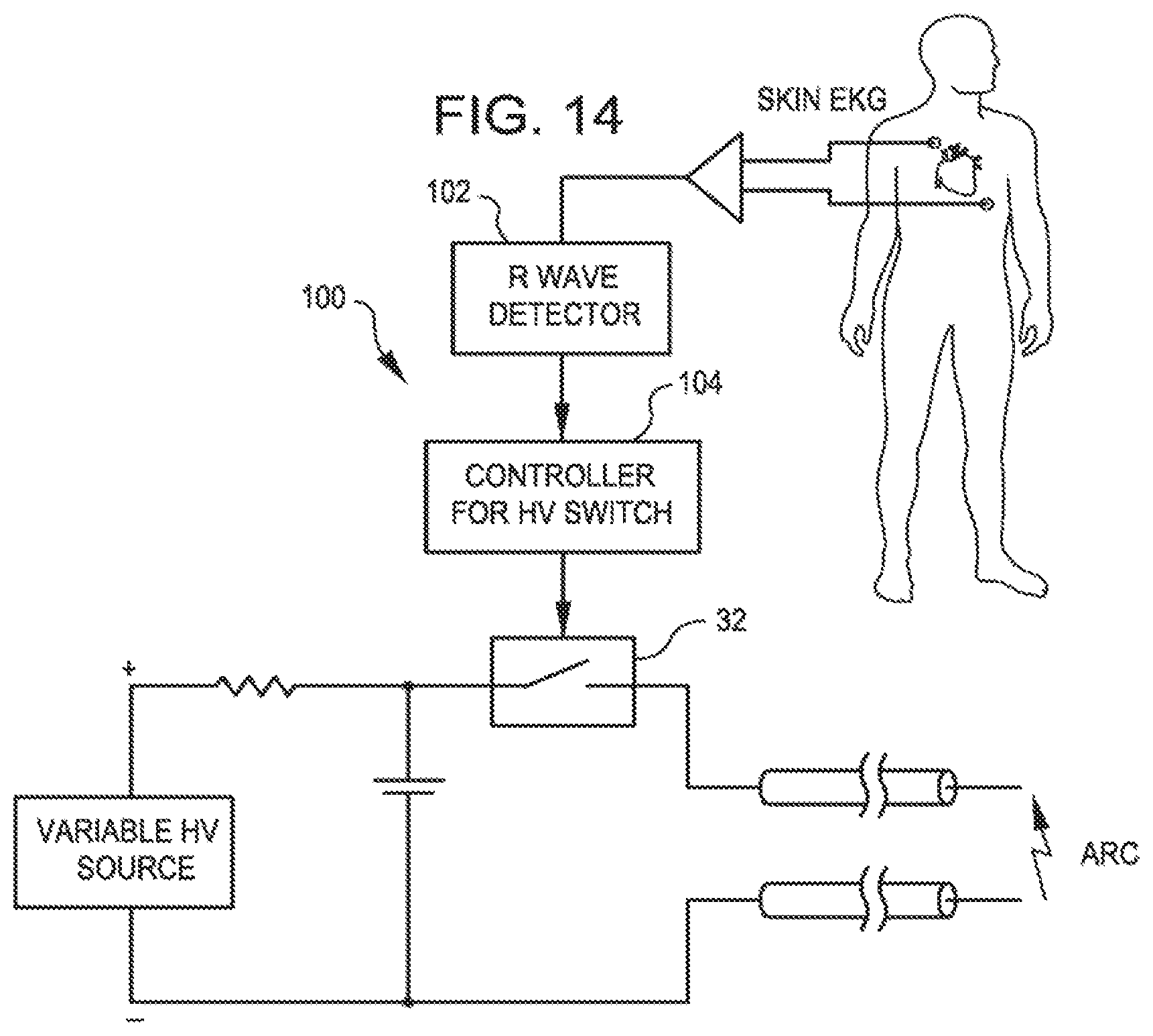
The system may further comprise an R wave detector that synchronizes the mechanical shock waves with cardiac R waves.
The at least one electrode may include a single metallic electrode of a pair of metallic electrodes. The electrodes may be radially displaced from each other or longitudinally displaced from each other. The at least one electrode may be formed of stainless steel.
The balloon may be formed of non-compliant material or of compliant material. The dilating balloon may have at least one stress riser carried on its surface.
The catheter may further comprise a sensor that senses reflected energy. The sensor may be distal to the at least one electrode. The sensor may be disposed on the carrier.
The catheter may further comprise a reflector within the dilating balloon that focuses the shock waves. The reflector may form one of the at least one electrodes. The catheter has a center line and the reflector may be arranged to focus the shock waves off of the catheter center line.
The fluid may be saline. The fluid may include an x-ray contrast.
The catheter may further include a lumen for receiving a guide wire. The lumen may be defined by the carrier.
The invention further provides a method comprising the step of providing a catheter including an elongated carrier, a dilating balloon about the carrier in sealed relation thereto, the balloon being arranged to receive a fluid therein that inflates the balloon, and an arc generator including at least one electrode within the balloon that forms a mechanical shock wave within the balloon. The method further comprises the steps of inserting the catheter into a body lumen of a patient adjacent an obstruction of the body lumen, admitting fluid into the balloon, and applying high voltage pulses to the arc generator to form a series of mechanical shocks within the balloon.
The method may include the further step of detecting cardiac R waves of the patient's heart, and synchronizing the mechanical shocks with the detected R waves.
The method may further include the step of varying one of the repetition rate, amplitude and duration of the high voltage pulses to vary the intensity of the mechanical shock waves.
The method may include the further step of sensing reflected energy within the catheter.
The method may include the further step of placing a guide wire into the body lumen and guiding the catheter into the body lumen along the guide wire.
The method may include the further step of focusing the mechanical shockwaves. The mechanical shockwaves may be focused away from the catheter center axis.
The method may include the further steps of adding an x-ray contrast to the fluid and visualizing the catheter under fluoroscopy.
BRIEF DESCRIPTION OF THE DRAWINGS
For illustration and not limitation, some of the features of the present invention are set forth in the appended claims. The various embodiments of the invention, together with representative features and advantages thereof, may best be understood by making reference to the following description taken in conjunction with the accompanying drawings, in the several figures of which like reference numerals identify identical elements, and wherein:
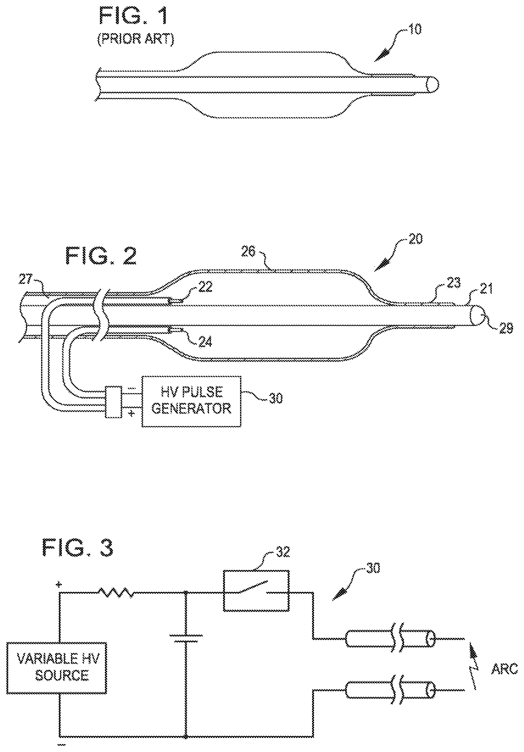
FIG. 1 is a view of the therapeutic end of a typical prior art over-the-wire angioplasty balloon catheter.
FIG. 2 is a side view of a dilating angioplasty balloon catheter with two electrodes within the balloon attached to a source of high voltage pulses according to one embodiment of the invention.
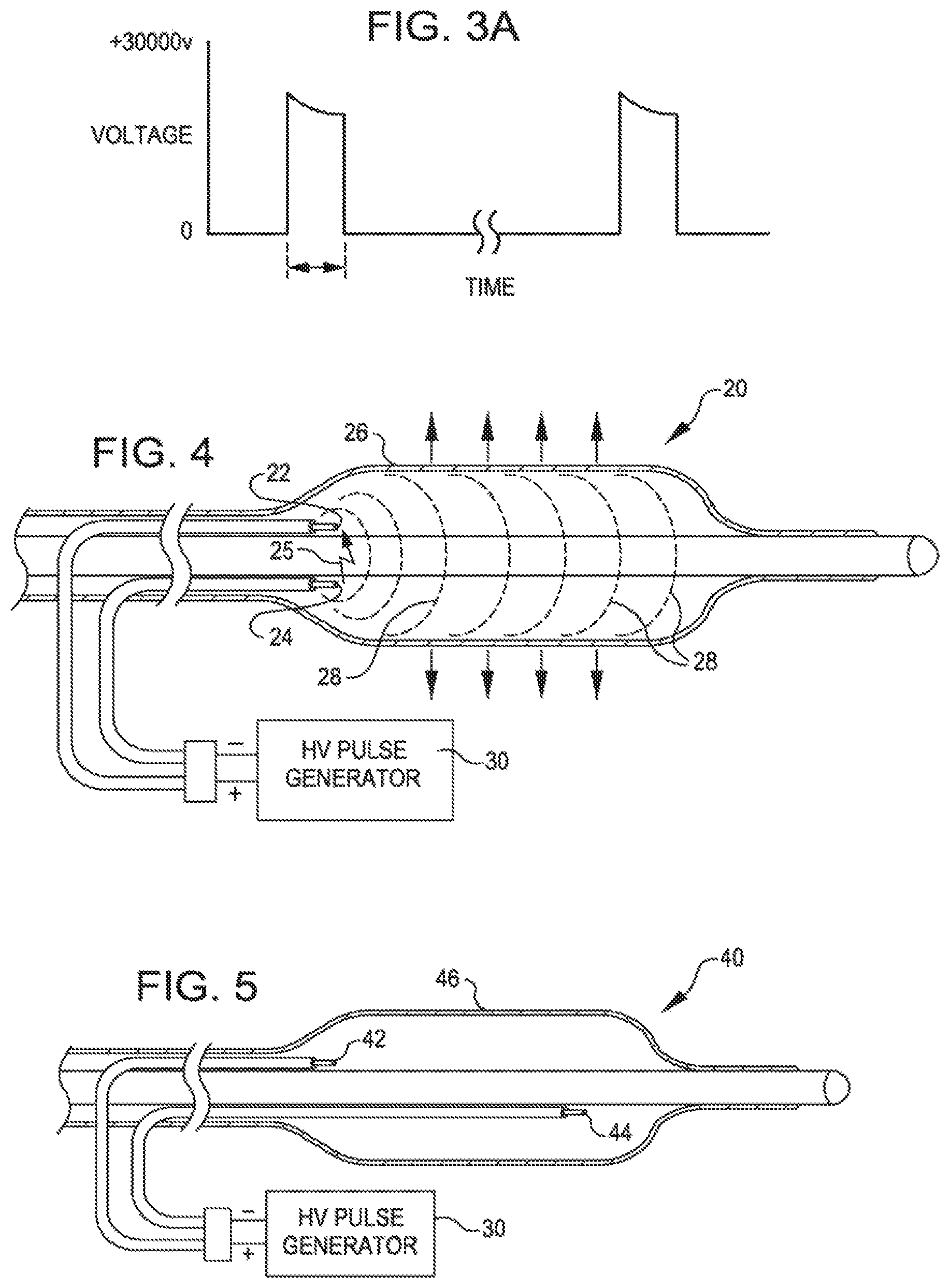
FIG. 3 is a schematic of a high voltage pulse generator.
FIG. 3A shows voltage pulses that may be obtained with the generator of FIG. 3.
FIG. 4 is a side view of the catheter of FIG. 2 showing an arc between the electrodes and simulations of the shock wave flow.
FIG. 5 is a side view of a dilating catheter with insulated electrodes within the balloon and displaced along the length of the balloon according to another embodiment of the invention.
FIG. 6 is a side view of a dilating catheter with insulated electrodes within the balloon displaced with a single pole in the balloon and a second being the ionic fluid inside the balloon according to a further embodiment of the invention.
FIG. 7 is a side view of a dilating catheter with insulated electrodes within the balloon and studs to reach the calcification according to a still further embodiment of the invention.
FIG. 8 is a side view of a dilating catheter with insulated electrodes within the balloon with raised ribs on the balloon according to still another embodiment of the invention.
FIG. 8A is a front view of the catheter of FIG. 8.
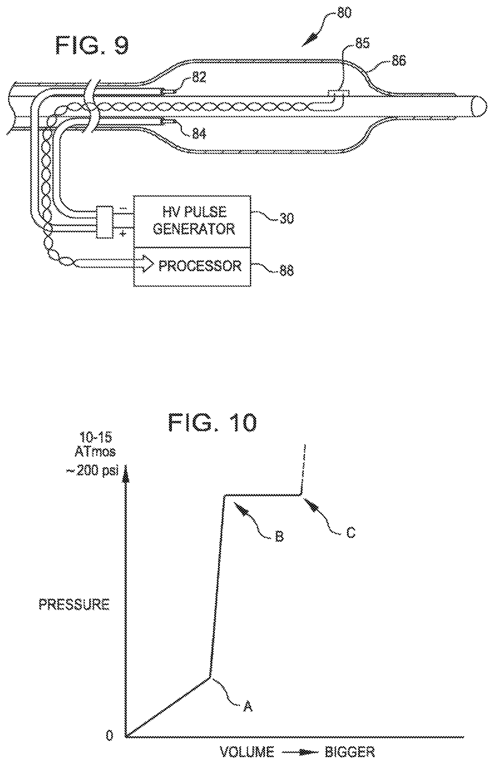
FIG. 9 is a side view of a dilating catheter with insulated electrodes within the balloon and a sensor to detect reflected signals according to a further embodiment of the invention.
FIG. 10 is a pressure volume curve of a prior art balloon breaking a calcified lesion.
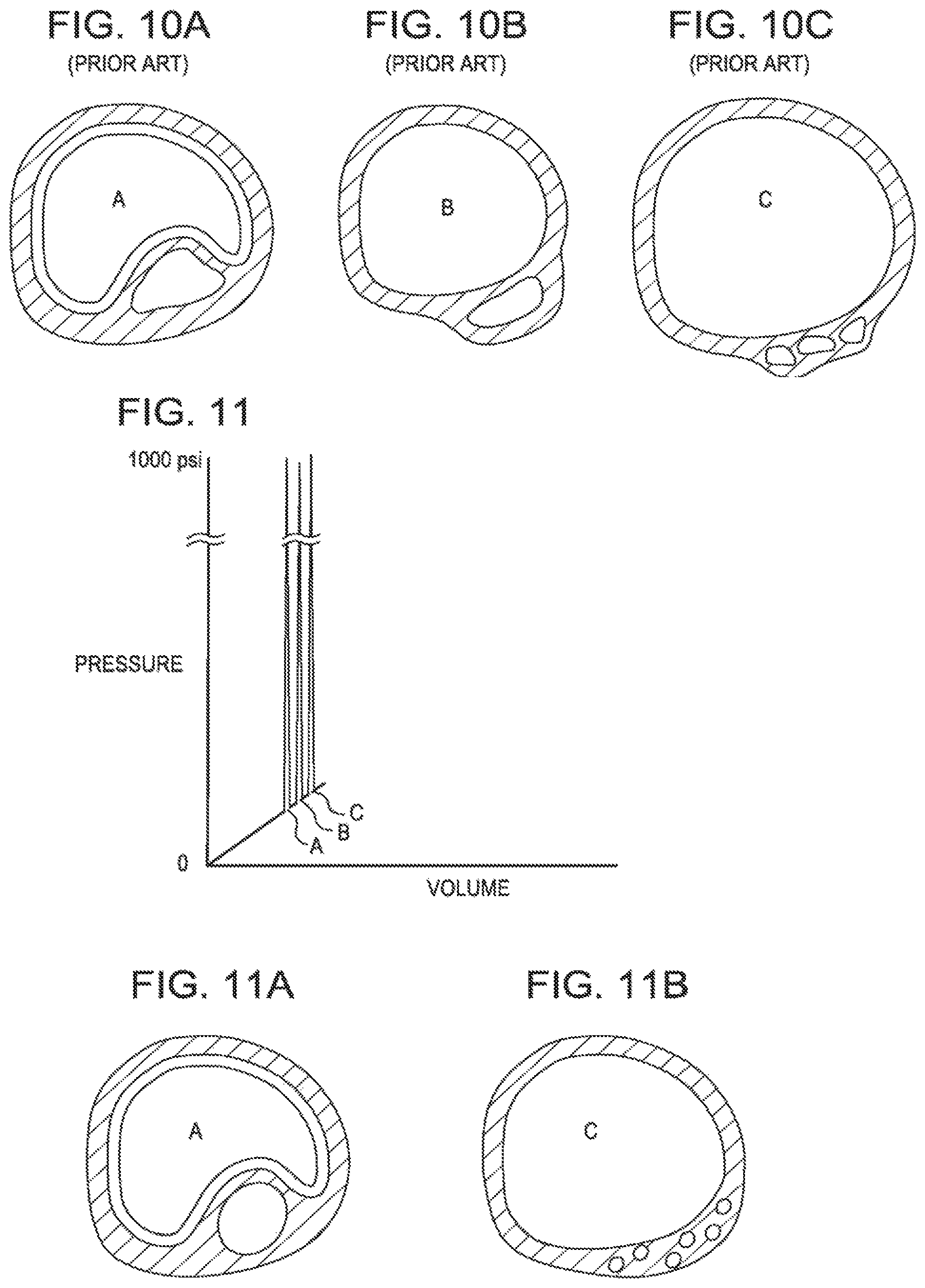
FIG. 10A is a sectional view of a balloon expanding freely within a vessel.
FIG. 10B is a sectional view of a balloon constrained to the point of breaking in a vessel.
FIG. 10C is a sectional view of a balloon after breaking within the vessel.
FIG. 11 is a pressure volume curve showing the various stages in the breaking of a calcified lesion with shock waves according to an embodiment of the invention.
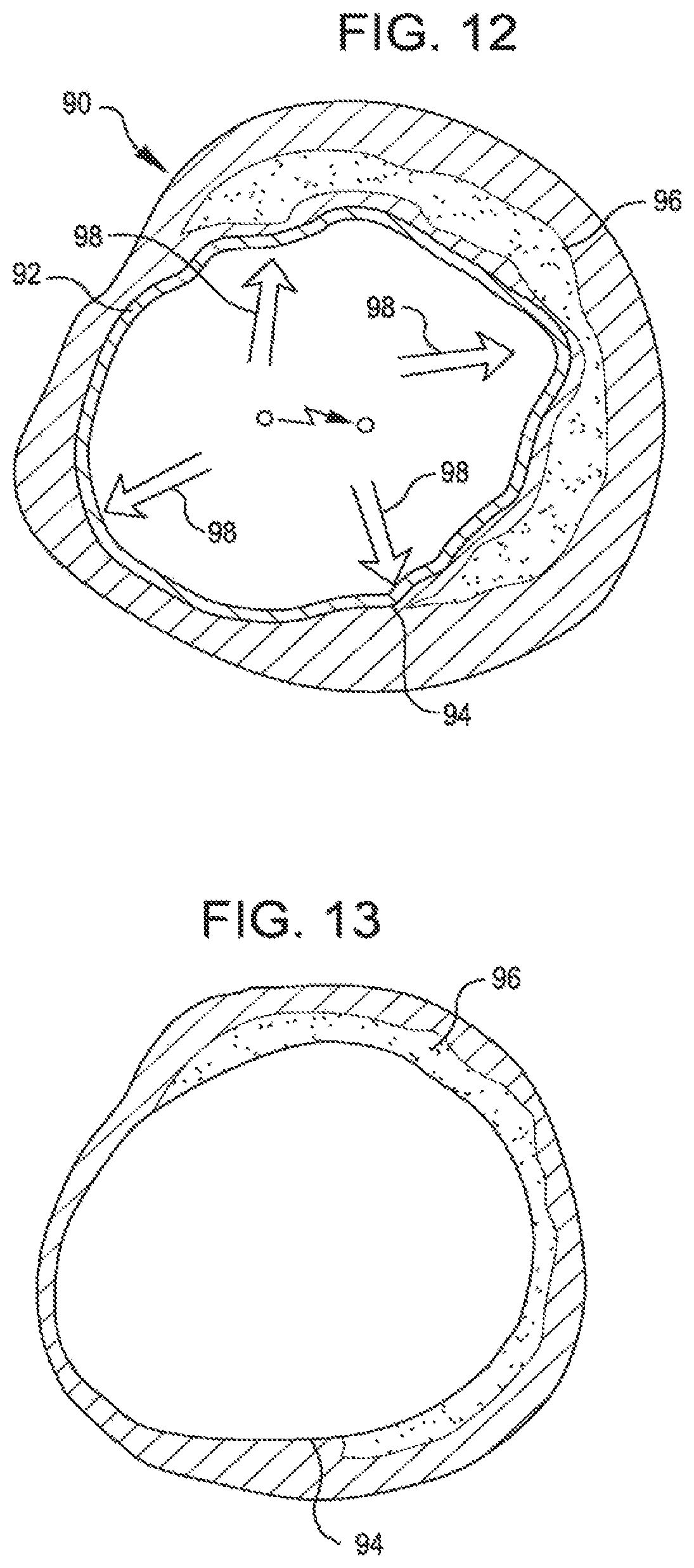
FIG. 11A is a sectional view showing a compliant balloon within a vessel.
FIG. 11B is a sectional view showing pulverized calcification on a vessel wall.
FIG. 12 illustrates shock waves delivered through the balloon wall and endothelium to a calcified lesion.
FIG. 13 shows calcified plaque pulverized and smooth a endothelium restored by the expanded balloon after pulverization.
FIG. 14 is a schematic of a circuit that uses a surface EKG to synchronize the shock wave to the "R" wave for treating vessels near the heart.
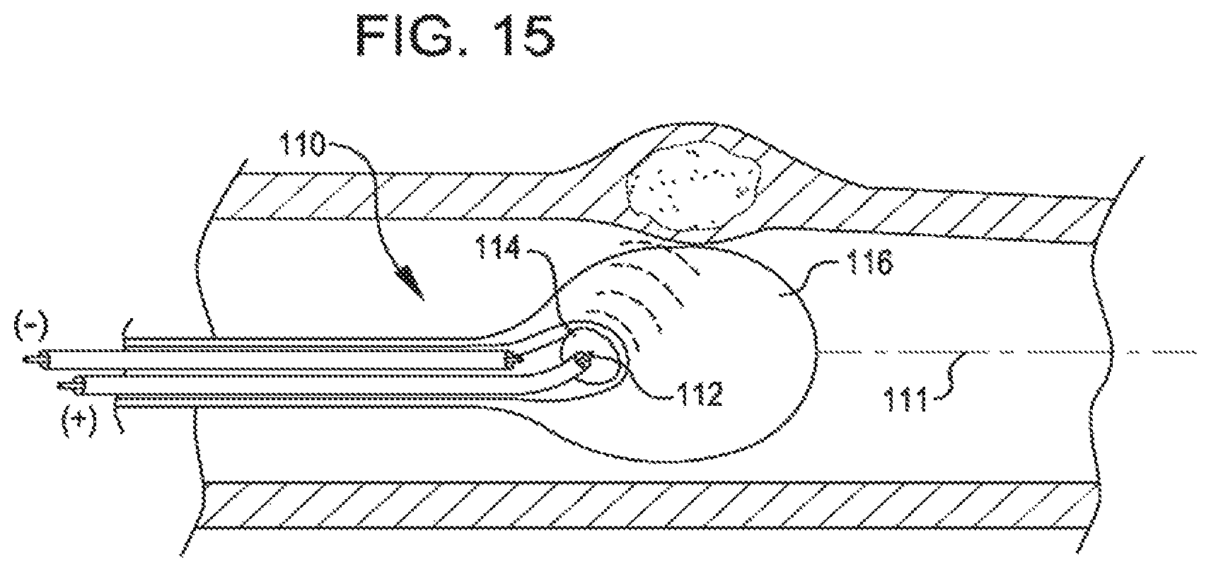
FIG. 15 is a side view, partly cut away, of a dilating catheter with a parabolic reflector acting as one electrode and provides a focused shock wave inside a fluid filled compliant balloon.
DETAILED DESCRIPTION OF THE INVENTION
FIG. 1 is a view of the therapeutic end of a typical prior art over-the-wire angioplasty balloon catheter 10. Such catheters are usually non-complaint with a fixed maximum dimension when expanded with a fluid such as saline.
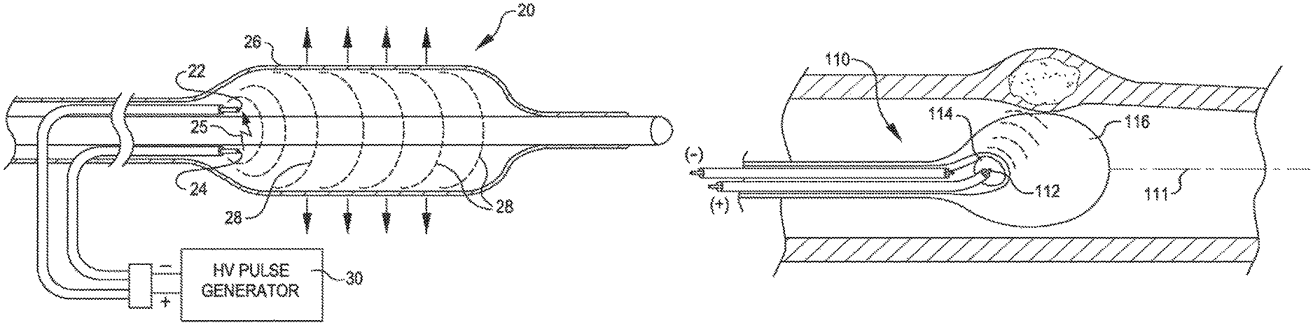
FIG. 2 is a view of a dilating angioplasty balloon catheter 20 according to an embodiment of the invention. The catheter 20 includes an elongated carrier, such as a hollow sheath 21, and a dilating balloon 26 formed about the sheath 21 in sealed relation thereto at a seal 23. The balloon 26 forms an annular channel 27 about the sheath 21 through which fluid, such as saline, may be admitted into the balloon to inflate the balloon. The channel 27 further permits the balloon 26 to be provided with two electrodes 22 and 24 within the fluid filled balloon 26. The electrodes 22 and 24 are attached to a source of high voltage pulses 30. The electrodes 22 and 24 are formed of metal, such as stainless steel, and are placed a controlled distance apart to allow a reproducible arc for a given voltage and current. The electrical arcs between electrodes 22 and 24 in the fluid are used to generate shock waves in the fluid. The variable high voltage pulse generator 30 is used to deliver a stream of pulses to the electrodes 22 and 24 to create a stream of shock waves within the balloon 26 and within the artery being treated (not shown). The magnitude of the shock waves can be controlled by controlling the magnitude of the pulsed voltage, the current, the duration and repetition rate. The insulating nature of the balloon 26 protects the patient from electrical shocks.
The balloon 26 may be filled with water or saline in order to gently fix the balloon in the walls of the artery in the direct proximity with the calcified lesion. The fluid may also contain an x-ray contrast to permit fluoroscopic viewing of the catheter during use. The carrier 21 includes a lumen 29 through which a guidewire (not shown) may be inserted to guide the catheter into position. Once positioned the physician or operator can start with low energy shock waves and increase the energy as needed to crack the calcified plaque. Such shockwaves will be conducted through the fluid, through the balloon, through the blood and vessel wall to the calcified lesion where the energy will break the hardened plaque without the application of excessive pressure by the balloon on the walls of the artery.
FIG. 3 is a schematic of the high voltage pulse generator 30. FIG. 3A shows a resulting waveform. The voltage needed will depend on the gap between the electrodes and generally 100 to 3000 volts. The high voltage switch 32 can be set to control the duration of the pulse. The pulse duration will depend on the surface area of the electrodes 22 and 24 and needs to be sufficient to generate a gas bubble at the surface of the electrode causing a plasma arc of electric current to jump the bubble and create a rapidly expanding and collapsing bubble, which creates the mechanical shock wave in the balloon. Such shock waves can be as short as a few microseconds.
FIG. 4 is a cross sectional view of the shockwave catheter 20 showing an arc 25 between the electrodes 22 and 24 and simulations of the shock wave flow 28. The shock wave 28 will radiate out from the electrodes 22 and 24 in all directions and will travel through the balloon 26 to the vessel where it will break the calcified lesion into smaller pieces.
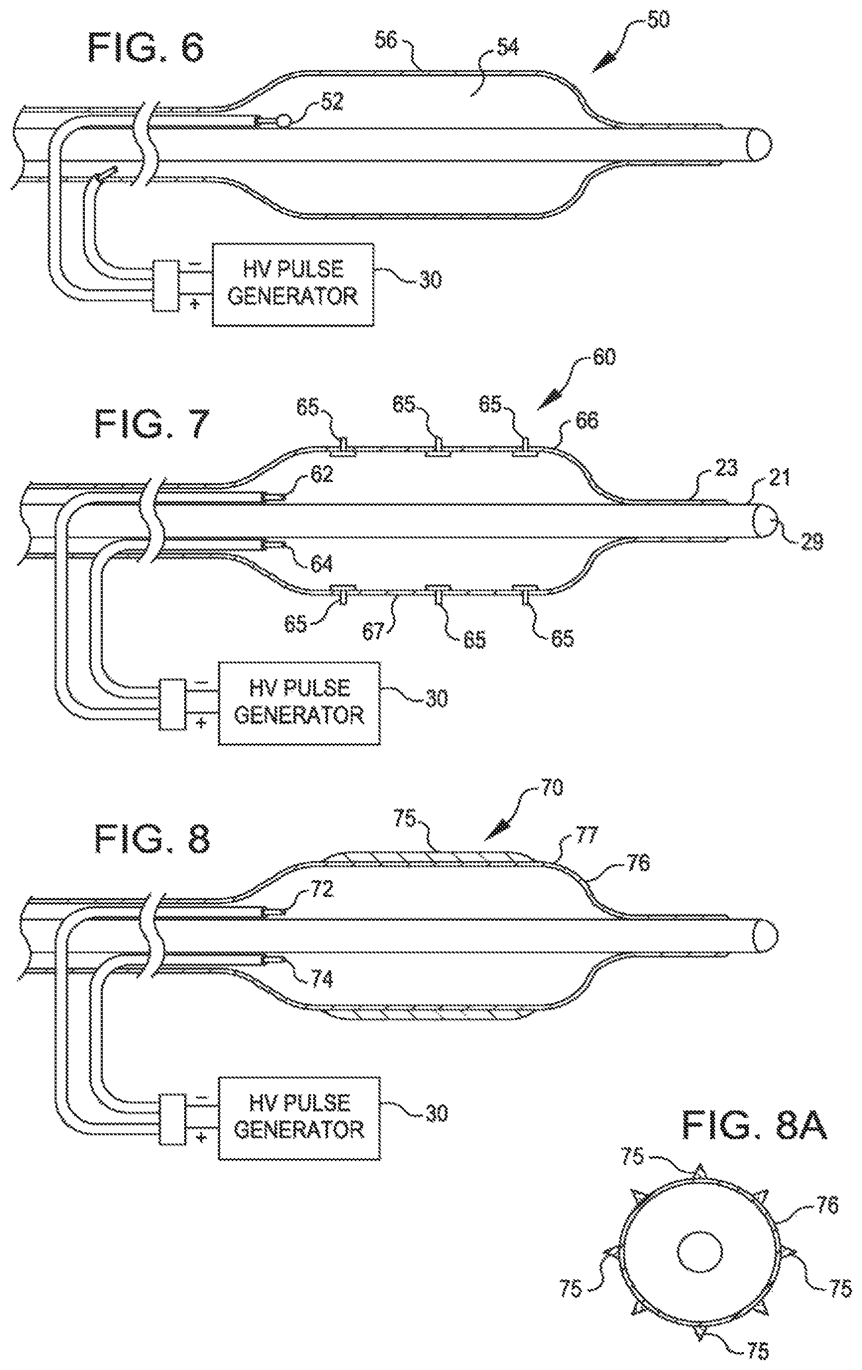
FIG. 5 shows another dilating catheter 40. It has insulated electrodes 42 and 44 within the balloon 46 displaced along the length of the balloon 46.
FIG. 6 shows a dilating catheter 50 with an insulated electrode 52 within the balloon 56. The electrode is a single electrode pole in the balloon, a second pole being the ionic fluid 54 inside the balloon. This unipolar configuration uses the ionic fluid as the other electrical pole and permits a smaller balloon and catheter design for low profile balloons. The ionic fluid is generator 30.
FIG. 7 is another dilating 60 catheter with electrodes 62 and 64 within the balloon 66 and studs 65 to reach the calcification. The studs 65 form mechanical stress risers on the balloon surface 67 and are designed to mechanically conduct the shock wave through the intimal layer of tissue of the vessel and deliver it directly to the calcified lesion.
FIG. 8 is another dilating catheter 70 with electrodes 72 and 74 within the balloon 76 and with raised ribs 75 on the surface 77 of the balloon 76. The raised ribs 75 (best seen in FIG. 8A) form stress risers that will focus the shockwave energy to linear regions of the calcified plaque.
FIG. 9 is a further dilating catheter 80 with electrodes 82 and 84 within the balloon 86. The catheter 80 further includes a sensor 85 to detect reflected signals. Reflected signals from the calcified plaque can be processed by a processor 88 to determine quality of the calcification and quality of pulverization of the lesion.
FIG. 10 is a pressure volume curve of a prior art balloon breaking a calcified lesion. FIG. 10B shows the build up of energy within the balloon (region A to B) and FIG. 10C shows the release of the energy (region B to C) when the calcification breaks. At region C the artery is expanded to the maximum dimension of the balloon. Such a dimension can lead to injury to the vessel walls. FIG. 10A shows the initial inflation of the balloon.
FIG. 11 is a pressure volume curve showing the various stages in the breaking of a calcified lesion with shock waves according to the embodiment. The balloon is expanded with a saline fluid and can be expanded to fit snugly to the vessel wall (Region A) (FIG. 11A) but this is not a requirement. As the High Voltage pulses generate shock waves (Region B and C) extremely high pressures, extremely short in duration will chip away the calcified lesion slowly and controllably expanding the opening in the vessel to allow blood to flow un-obstructed (FIG. 11B).
FIG. 12 shows, in a cutaway view, shock waves 98 delivered in all directions through the wall 92 of a saline filled balloon 90 and intima 94 to a calcified lesion 96. The shock waves 98 pulverize the lesion 96. The balloon wall 92 may be formed of non-compliant or compliant material to contact the intima 94.
FIG. 13 shows calcified plaque 96 pulverized by the shock waves. The intima 94 is smoothed and restored after the expanded balloon (not shown) has pulverized and reshaped the plaque into the vessel wall.
FIG. 14 is a schematic of a circuit 100 that uses the generator circuit 30 of FIG. 3 and a surface EKG 102 to synchronize the shock wave to the "R" wave for treating vessels near the heart. The circuit 100 includes an R-wave detector 102 and a controller 104 to control the high voltage switch 32. Mechanical shocks can stimulate heart muscle and could lead to an arrhythmia. While it is unlikely that shockwaves of such short duration as contemplated herein would stimulate the heart, by synchronizing the pulses (or bursts of pulses) with the R-wave, an additional degree of safety is provided when used on vessels of the heart or near the heart. While the balloon in the current drawings will provide an electrical isolation of the patient from the current, a device could be made in a non-balloon or non-isolated manner using blood as the fluid. In such a device, synchronization to the R-wave would significantly improve the safety against unwanted arrhythmias.
FIG. 15 shows a still further dilation catheter 110 wherein a shock wave is focused with a parabolic reflector 114 acting as one electrode inside a fluid filled compliant balloon 116. The other electrode 112 is located at the coaxial center of the reflector 114. By using the reflector as one electrode, the shock wave can be focused and therefore pointed at an angle (45 degrees, for example) off the center line 111 of the catheter artery. In this configuration, the other electrode 112 will be designed to be at the coaxial center of the reflector and designed to arc to the reflector 114 through the fluid. The catheter can be rotated if needed to break hard plaque as it rotates and delivers shockwaves.
The subject method can be used with various electrode designs. For example, the electrodes can be provided with a low profile to improve the ability of the catheter to navigate small vessels. An example of such a low profile electrode design can be found in U.S. Pat. No. 8,747,416. It may also desirable to adjust the length of the voltage pulses to reduce excess heat generation. One approach for achieving this goal is described in U.S. Pat. No. 8,728,091.
While particular embodiments of the present invention have been shown and described, modifications may be made. For example, instead of manual actuation and spring loaded return of the valves used herein, constructions are possible which perform in a reversed manner by being spring actuated and manually returned. It is therefore intended in the appended claims to cover all such changes and modifications which fall within the true spirit and scope of the invention as defined by those claims.
* * * * *
References
-
healio.com/cardiac-vascular-intervention/peripheral/news/online/%7Bf96c1e20-b4a9-4167-bdb8-254e86a8182a%7D/shockwave-attracts-additional-investment-from-abiomed-has-ipo
-
investors.com/news/technology/shockwave-medical-ipo-soars-trading
-
dictionary.com/browse/angioplasty
-
dicardiology.com/product/fda-clearslithoplasty-balloon-shatters-calcified-lesions-ultrasound
-
meddeviceonline.com/doc/angioplasty-balloons-0001
-
medlineplus.gov/angioplasty.html
-
cardiovascularnews.com/intravascular-lithotripsy-anovel-technology-for-treating-calcified-coronary-stenoses
-
newsday.com/news/health/calcium-treatment-st-francis-hospital-1.27314331
-
shockwavemedical.com/wp-content/uploads/2018/12/PAD-IVL-Case-Set-Up.pdf
-
-
webmd.com/heart-disease/heart-failure/qa/what-is-the-definition-of-angioplasty
D00000
D00001
D00002
D00003
D00004
D00005
D00006
D00007
D00008
XML
uspto.report is an independent third-party trademark research tool that is not affiliated, endorsed, or sponsored by the United States Patent and Trademark Office (USPTO) or any other governmental organization. The information provided by uspto.report is based on publicly available data at the time of writing and is intended for informational purposes only.
While we strive to provide accurate and up-to-date information, we do not guarantee the accuracy, completeness, reliability, or suitability of the information displayed on this site. The use of this site is at your own risk. Any reliance you place on such information is therefore strictly at your own risk.
All official trademark data, including owner information, should be verified by visiting the official USPTO website at www.uspto.gov. This site is not intended to replace professional legal advice and should not be used as a substitute for consulting with a legal professional who is knowledgeable about trademark law.