Surgical instrument including a locking assembly
Beardsley , et al.
U.S. patent number 10,702,265 [Application Number 15/807,690] was granted by the patent office on 2020-07-07 for surgical instrument including a locking assembly. This patent grant is currently assigned to COVIDIEN LP. The grantee listed for this patent is Covidien LP. Invention is credited to John W. Beardsley, Stanislaw Marczyk.


View All Diagrams
| United States Patent | 10,702,265 |
| Beardsley , et al. | July 7, 2020 |
Surgical instrument including a locking assembly
Abstract
A surgical instrument including a handle portion, a body portion, an articulating tool assembly and a locking assembly is disclosed. The handle portion includes a movable handle. The body portion extends distally from the handle portion and defines a first longitudinal axis. The articulating tool assembly defines a second longitudinal axis and is movable from a first position where the second longitudinal axis is substantially aligned with the first longitudinal axis to at least a second position where the second longitudinal axis is at an angle to the first longitudinal axis. The locking assembly includes a member that is advanceable distally with respect to the body portion. The member engages the articulating tool assembly upon manipulation of the movable handle to move an anvil and a cartridge assembly in approximation with one another to help maintain the articulating tool assembly in its first position.
| Inventors: | Beardsley; John W. (Wallingford, CT), Marczyk; Stanislaw (Stratford, CT) | ||||||||||
|---|---|---|---|---|---|---|---|---|---|---|---|
| Applicant: |
|
||||||||||
| Assignee: | COVIDIEN LP (Mansfield,
MA) |
||||||||||
| Family ID: | 62142931 | ||||||||||
| Appl. No.: | 15/807,690 | ||||||||||
| Filed: | November 9, 2017 |
Prior Publication Data
| Document Identifier | Publication Date | |
|---|---|---|
| US 20180064439 A1 | Mar 8, 2018 | |
Related U.S. Patent Documents
| Application Number | Filing Date | Patent Number | Issue Date | ||
|---|---|---|---|---|---|
| 14040964 | Sep 30, 2013 | 9820737 | |||
| 11544479 | Oct 6, 2006 | ||||
| Current U.S. Class: | 1/1 |
| Current CPC Class: | A61B 17/072 (20130101); A61B 17/105 (20130101); A61B 17/07207 (20130101); A61B 17/068 (20130101); A61B 17/115 (20130101); A61B 2017/00526 (20130101); A61B 2017/00473 (20130101); A61B 2017/2936 (20130101); A61B 2017/07271 (20130101); A61B 2017/07278 (20130101); A61B 2017/00845 (20130101); A61B 2017/07214 (20130101); A61B 17/0686 (20130101); A61B 2017/00853 (20130101); A61B 2017/07285 (20130101); A61B 2017/320052 (20130101); A61B 2017/0023 (20130101); A61B 2017/2927 (20130101); A61B 2017/0084 (20130101); A61B 2017/2943 (20130101); A61B 2017/2946 (20130101); A61B 2017/00964 (20130101); A61B 2017/2902 (20130101); A61B 2017/0046 (20130101) |
| Current International Class: | A61B 17/068 (20060101); A61B 17/072 (20060101); A61B 17/29 (20060101); A61B 17/32 (20060101); A61B 17/10 (20060101); A61B 17/115 (20060101); A61B 17/00 (20060101) |
References Cited [Referenced By]
U.S. Patent Documents
| 3079606 | March 1963 | Bobrov et al. |
| 3490675 | January 1970 | Green et al. |
| 3499591 | March 1970 | Green |
| 3777538 | December 1973 | Weatherly et al. |
| 3882854 | May 1975 | Hulka et al. |
| 4027510 | June 1977 | Hiltebrandt |
| 4086926 | May 1978 | Green et al. |
| 4244372 | January 1981 | Kapitanov et al. |
| 4429695 | February 1984 | Green |
| 4505414 | March 1985 | Filipi |
| 4520817 | June 1985 | Green |
| 4589413 | May 1986 | Malyshev et al. |
| 4596351 | June 1986 | Fedotov et al. |
| 4602634 | July 1986 | Barkley |
| 4605001 | August 1986 | Rothfuss et al. |
| 4608981 | September 1986 | Rothfuss et al. |
| 4610383 | September 1986 | Rothfuss et al. |
| 4633861 | January 1987 | Chow et al. |
| 4633874 | January 1987 | Chow et al. |
| 4671445 | June 1987 | Barker et al. |
| 4700703 | October 1987 | Resnick et al. |
| 4703887 | November 1987 | Clanton et al. |
| 4728020 | March 1988 | Green et al. |
| 4752024 | June 1988 | Green et al. |
| 4784137 | November 1988 | Kulik et al. |
| 4863088 | September 1989 | Redmond et al. |
| 4869415 | September 1989 | Fox |
| 4892244 | January 1990 | Fox et al. |
| 4955959 | September 1990 | Tompkins et al. |
| 4978049 | December 1990 | Green |
| 4991764 | February 1991 | Mericle |
| 5014899 | May 1991 | Presty et al. |
| 5031814 | July 1991 | Tompkins et al. |
| 5040715 | August 1991 | Green et al. |
| 5065929 | November 1991 | Schulze et al. |
| 5071430 | December 1991 | de Salis et al. |
| 5074454 | December 1991 | Peters |
| 5083695 | January 1992 | Foslien et al. |
| 5084057 | January 1992 | Green et al. |
| 5106008 | April 1992 | Tompkins et al. |
| 5111987 | May 1992 | Moeinzadeh et al. |
| 5129570 | July 1992 | Schulze et al. |
| 5141144 | August 1992 | Foslien et al. |
| 5156315 | October 1992 | Green et al. |
| 5156614 | October 1992 | Green et al. |
| 5163943 | November 1992 | Mohiuddin et al. |
| 5170925 | December 1992 | Madden et al. |
| 5171247 | December 1992 | Hughett et al. |
| 5173133 | December 1992 | Morin et al. |
| 5180092 | January 1993 | Crainich |
| 5188274 | February 1993 | Moeinzadeh et al. |
| 5220928 | June 1993 | Oddsen et al. |
| 5221036 | June 1993 | Takase |
| 5242457 | September 1993 | Akopov et al. |
| 5246156 | September 1993 | Rothfuss et al. |
| 5253793 | October 1993 | Green et al. |
| 5263629 | November 1993 | Trumbull et al. |
| RE34519 | January 1994 | Fox et al. |
| 5275323 | January 1994 | Schulze et al. |
| 5282807 | February 1994 | Knoepfler |
| 5289963 | March 1994 | McGarry et al. |
| 5307976 | May 1994 | Olson et al. |
| 5308576 | May 1994 | Green et al. |
| 5312023 | May 1994 | Green et al. |
| 5318221 | June 1994 | Green et al. |
| 5326013 | July 1994 | Green et al. |
| 5328077 | July 1994 | Lou |
| 5330486 | July 1994 | Wilk |
| 5332142 | July 1994 | Robinson et al. |
| 5336232 | August 1994 | Green et al. |
| 5344061 | September 1994 | Crainich |
| 5352238 | October 1994 | Green et al. |
| 5356064 | October 1994 | Green et al. |
| 5358506 | October 1994 | Green et al. |
| 5364001 | November 1994 | Bryan |
| 5364002 | November 1994 | Green et al. |
| 5364003 | November 1994 | Williamson, IV |
| 5366133 | November 1994 | Geiste |
| 5376095 | December 1994 | Ortiz |
| 5379933 | January 1995 | Green et al. |
| 5381943 | January 1995 | Allen et al. |
| 5382255 | January 1995 | Castro et al. |
| 5383880 | January 1995 | Hooven |
| 5389098 | February 1995 | Tsuruta et al. |
| 5395033 | March 1995 | Byrne et al. |
| 5395034 | March 1995 | Allen et al. |
| 5397046 | March 1995 | Savage et al. |
| 5397324 | March 1995 | Carroll et al. |
| 5403312 | April 1995 | Yates et al. |
| 5405072 | April 1995 | Zlock et al. |
| 5407293 | April 1995 | Crainich |
| 5413268 | May 1995 | Green et al. |
| 5415334 | May 1995 | Williamson et al. |
| 5415335 | May 1995 | Knodell, Jr. |
| 5417361 | May 1995 | Williamson, IV |
| 5423471 | June 1995 | Mastri et al. |
| 5425745 | June 1995 | Green et al. |
| 5431322 | July 1995 | Green et al. |
| 5431323 | July 1995 | Smith et al. |
| 5433721 | July 1995 | Hooven et al. |
| 5441193 | August 1995 | Gravener |
| 5445304 | August 1995 | Plyley et al. |
| 5447265 | September 1995 | Vidal et al. |
| 5452837 | September 1995 | Williamson, IV et al. |
| 5456401 | October 1995 | Green et al. |
| 5464300 | November 1995 | Crainich |
| 5465895 | November 1995 | Knodel et al. |
| 5467911 | November 1995 | Tsuruta et al. |
| 5470007 | November 1995 | Plyley et al. |
| 5470010 | November 1995 | Rothfuss et al. |
| 5472132 | December 1995 | Savage et al. |
| 5474566 | December 1995 | Alesi et al. |
| 5476206 | December 1995 | Green et al. |
| 5478003 | December 1995 | Green et al. |
| 5480089 | January 1996 | Blewett |
| 5482197 | January 1996 | Green et al. |
| 5484095 | January 1996 | Green et al. |
| 5484451 | January 1996 | Akopov et al. |
| 5485947 | January 1996 | Olson et al. |
| 5485952 | January 1996 | Fontayne |
| 5486185 | January 1996 | Freitas et al. |
| 5487499 | January 1996 | Sorrentino et al. |
| 5487500 | January 1996 | Knodel et al. |
| 5489058 | February 1996 | Plyley et al. |
| 5490856 | February 1996 | Person et al. |
| 5497933 | March 1996 | DeFonzo et al. |
| 5501689 | March 1996 | Green et al. |
| 5505363 | April 1996 | Green et al. |
| 5507426 | April 1996 | Young et al. |
| 5518163 | May 1996 | Hooven |
| 5518164 | May 1996 | Hooven |
| 5529235 | June 1996 | Boiarski et al. |
| 5531744 | July 1996 | Nardella et al. |
| 5535934 | July 1996 | Boiarski et al. |
| 5535935 | July 1996 | Vidal et al. |
| 5535937 | July 1996 | Boiarski et al. |
| 5540375 | July 1996 | Bolanos |
| 5542594 | August 1996 | McKean et al. |
| 5549628 | August 1996 | Cooper et al. |
| 5551622 | September 1996 | Yoon |
| 5553765 | September 1996 | Knodel et al. |
| 5554164 | September 1996 | Wilson et al. |
| 5554169 | September 1996 | Green et al. |
| 5560530 | October 1996 | Bolanos et al. |
| 5560532 | October 1996 | DeFonzo et al. |
| 5562239 | October 1996 | Boiarski et al. |
| 5562241 | October 1996 | Knodel et al. |
| 5562682 | October 1996 | Oberlin et al. |
| 5562701 | October 1996 | Huitema et al. |
| 5564615 | October 1996 | Bishop et al. |
| 5571116 | November 1996 | Bolanos et al. |
| 5573169 | November 1996 | Green et al. |
| 5573543 | November 1996 | Akopov et al. |
| 5575799 | November 1996 | Bolanos et al. |
| 5575803 | November 1996 | Cooper et al. |
| 5577654 | November 1996 | Bishop |
| 5579107 | November 1996 | Wright et al. |
| 5584425 | December 1996 | Savage et al. |
| 5586711 | December 1996 | Plyley et al. |
| 5588580 | December 1996 | Paul et al. |
| 5588581 | December 1996 | Conlon et al. |
| 5597107 | January 1997 | Knodel et al. |
| 5601224 | February 1997 | Bishop et al. |
| 5607095 | March 1997 | Smith et al. |
| 5615820 | April 1997 | Viola |
| 5618291 | April 1997 | Thompson et al. |
| 5624452 | April 1997 | Yates |
| 5626587 | May 1997 | Bishop et al. |
| 5628446 | May 1997 | Geiste et al. |
| 5630539 | May 1997 | Plyley et al. |
| 5630540 | May 1997 | Blewett |
| 5630541 | May 1997 | Williamson, IV et al. |
| 5632432 | May 1997 | Schulze et al. |
| 5634584 | June 1997 | Okorocha et al. |
| 5636780 | June 1997 | Green et al. |
| 5645209 | July 1997 | Green et al. |
| 5647526 | July 1997 | Green et al. |
| 5651491 | July 1997 | Heaton et al. |
| 5653373 | August 1997 | Green et al. |
| 5653374 | August 1997 | Young et al. |
| 5653721 | August 1997 | Knodel et al. |
| 5655698 | August 1997 | Yoon |
| 5657921 | August 1997 | Young et al. |
| 5658300 | August 1997 | Bito et al. |
| 5662258 | September 1997 | Knodel et al. |
| 5662259 | September 1997 | Yoon |
| 5662260 | September 1997 | Yoon |
| 5662662 | September 1997 | Bishop et al. |
| 5662666 | September 1997 | Onuki et al. |
| 5665085 | September 1997 | Nardella |
| 5667517 | September 1997 | Hooven |
| 5669544 | September 1997 | Schulze et al. |
| 5673840 | October 1997 | Schulze et al. |
| 5673841 | October 1997 | Schulze et al. |
| 5673842 | October 1997 | Bittner et al. |
| 5676674 | October 1997 | Bolanos et al. |
| 5680981 | October 1997 | Mililli et al. |
| 5680982 | October 1997 | Schulze et al. |
| 5680983 | October 1997 | Plyley et al. |
| 5690269 | November 1997 | Bolanos et al. |
| 5692668 | December 1997 | Schulze et al. |
| 5697542 | December 1997 | Knodel et al. |
| 5702409 | December 1997 | Rayburn et al. |
| 5704534 | January 1998 | Huitema et al. |
| 5706997 | January 1998 | Green et al. |
| 5709334 | January 1998 | Sorrentino et al. |
| 5711472 | January 1998 | Bryan |
| 5713505 | February 1998 | Huitema |
| 5715988 | February 1998 | Palmer |
| 5716366 | February 1998 | Yates |
| 5718359 | February 1998 | Palmer et al. |
| 5725536 | March 1998 | Oberlin et al. |
| 5725554 | March 1998 | Simon et al. |
| 5728110 | March 1998 | Vidal et al. |
| 5732806 | March 1998 | Foshee et al. |
| 5735848 | April 1998 | Yates et al. |
| 5743456 | April 1998 | Jones et al. |
| 5749893 | May 1998 | Vidal et al. |
| 5752644 | May 1998 | Bolanos et al. |
| 5762255 | June 1998 | Chrisman et al. |
| 5762256 | June 1998 | Mastri et al. |
| 5769303 | June 1998 | Knodel et al. |
| 5769892 | June 1998 | Kingwell |
| 5772099 | June 1998 | Gravener |
| 5772673 | June 1998 | Cuny et al. |
| 5779130 | July 1998 | Alesi et al. |
| 5779131 | July 1998 | Knodel et al. |
| 5779132 | July 1998 | Knodel et al. |
| 5782396 | July 1998 | Mastri et al. |
| 5782397 | July 1998 | Koukline |
| 5782834 | July 1998 | Lucey et al. |
| 5785232 | July 1998 | Vidal et al. |
| 5794834 | August 1998 | Hamblin et al. |
| 5797536 | August 1998 | Smith et al. |
| 5797537 | August 1998 | Oberlin et al. |
| 5797538 | August 1998 | Heaton et al. |
| 5810811 | September 1998 | Yates et al. |
| 5810855 | September 1998 | Rayburn et al. |
| 5814055 | September 1998 | Knodel et al. |
| 5814057 | September 1998 | Oi et al. |
| 5816471 | October 1998 | Plyley et al. |
| 5817109 | October 1998 | McGarry et al. |
| 5820009 | October 1998 | Melling et al. |
| 5823066 | October 1998 | Huitema et al. |
| 5826776 | October 1998 | Schulze et al. |
| 5829662 | November 1998 | Allen et al. |
| 5833695 | November 1998 | Yoon |
| 5836147 | November 1998 | Schnipke |
| 5862972 | January 1999 | Green et al. |
| 5865361 | February 1999 | Milliman et al. |
| 5871135 | February 1999 | Williamson, IV et al. |
| 5873873 | February 1999 | Smith et al. |
| 5878938 | March 1999 | Bittner et al. |
| 5893506 | April 1999 | Powell |
| 5894979 | April 1999 | Powell |
| 5897562 | April 1999 | Bolanos et al. |
| 5901895 | May 1999 | Heaton et al. |
| 5911352 | June 1999 | Racenet et al. |
| 5911353 | June 1999 | Bolanos et al. |
| 5918791 | July 1999 | Sorrentino et al. |
| 5919198 | July 1999 | Graves, Jr. et al. |
| 5922001 | July 1999 | Yoon |
| 5931847 | August 1999 | Bittner et al. |
| 5941442 | August 1999 | Geiste et al. |
| 5954259 | September 1999 | Viola et al. |
| 5964774 | October 1999 | McKean et al. |
| 5980510 | November 1999 | Tsonton et al. |
| 5988479 | November 1999 | Palmer |
| 6004335 | December 1999 | Vaitekunas et al. |
| 6010054 | January 2000 | Johnson et al. |
| 6032849 | March 2000 | Mastri et al. |
| 6045560 | April 2000 | McKean et al. |
| 6063097 | May 2000 | Oi et al. |
| 6079606 | June 2000 | Milliman et al. |
| 6099551 | August 2000 | Gabbay |
| 6109500 | August 2000 | Alli et al. |
| 6131789 | October 2000 | Schulze et al. |
| 6131790 | October 2000 | Piraka |
| 6155473 | December 2000 | Tompkins et al. |
| 6197017 | March 2001 | Brock et al. |
| 6202914 | March 2001 | Geiste et al. |
| 6241139 | June 2001 | Milliman et al. |
| 6250532 | June 2001 | Green |
| 6264086 | July 2001 | McGuckin, Jr. |
| 6264087 | July 2001 | Whitman |
| 6269977 | August 2001 | Moore |
| 6279809 | August 2001 | Nicolo |
| 6315183 | November 2001 | Piraka |
| 6315184 | November 2001 | Whitman |
| 6325810 | December 2001 | Hamilton et al. |
| 6330965 | December 2001 | Milliman et al. |
| 6391038 | May 2002 | Vargas et al. |
| 6398797 | June 2002 | Bombard et al. |
| 6436097 | August 2002 | Nardella |
| 6439446 | August 2002 | Perry et al. |
| 6443973 | September 2002 | Whitman |
| 6463623 | October 2002 | Ahn et al. |
| 6478804 | November 2002 | Vargas et al. |
| 6488196 | December 2002 | Fenton, Jr. |
| 6503257 | January 2003 | Grant et al. |
| 6505768 | January 2003 | Whitman |
| 6544274 | April 2003 | Danitz et al. |
| 6554844 | April 2003 | Lee et al. |
| 6565554 | May 2003 | Niemeyer |
| 6587750 | July 2003 | Gerbi et al. |
| 6592597 | July 2003 | Grant et al. |
| 6594552 | July 2003 | Nowlin et al. |
| 6602252 | August 2003 | Mollenauer |
| 6612053 | September 2003 | Liao |
| 6619529 | September 2003 | Green et al. |
| D480808 | October 2003 | Wells et al. |
| 6644532 | November 2003 | Green et al. |
| 6656193 | December 2003 | Grant et al. |
| 6669073 | December 2003 | Milliman et al. |
| 6681978 | January 2004 | Geiste et al. |
| 6698643 | March 2004 | Whitman |
| 6716232 | April 2004 | Vidal et al. |
| 6722552 | April 2004 | Fenton, Jr. |
| 6731473 | May 2004 | Li et al. |
| 6755338 | June 2004 | Hahnen et al. |
| 6783524 | August 2004 | Anderson et al. |
| 6786382 | September 2004 | Hoffman |
| 6808262 | October 2004 | Chapoy et al. |
| 6817509 | November 2004 | Geiste et al. |
| 6830174 | December 2004 | Hillstead et al. |
| 6835199 | December 2004 | McGuckin, Jr. et al. |
| 6843403 | January 2005 | Whitman |
| RE38708 | March 2005 | Bolanos et al. |
| 6877647 | April 2005 | Green et al. |
| 6879880 | April 2005 | Nowlin et al. |
| 6889116 | May 2005 | Jinno |
| 6905057 | June 2005 | Swayze et al. |
| 6945444 | September 2005 | Gresham et al. |
| 6953138 | October 2005 | Dworak et al. |
| 6953139 | October 2005 | Milliman et al. |
| 6959852 | November 2005 | Shelton, IV et al. |
| 6962594 | November 2005 | Thevenet |
| 6964363 | November 2005 | Wales et al. |
| 6978921 | December 2005 | Shelton, IV et al. |
| 6981628 | January 2006 | Wales |
| 6986451 | January 2006 | Mastri et al. |
| 6988649 | January 2006 | Shelton, IV et al. |
| 6991627 | January 2006 | Madhani et al. |
| 6994714 | February 2006 | Vargas et al. |
| 7000818 | February 2006 | Shelton, IV et al. |
| 7000819 | February 2006 | Swayze et al. |
| 7032799 | April 2006 | Viola et al. |
| 7044352 | May 2006 | Shelton, IV et al. |
| 7044353 | May 2006 | Mastri et al. |
| 7055730 | June 2006 | Ehrenfels et al. |
| 7055731 | June 2006 | Shelton, IV et al. |
| 7059508 | June 2006 | Shelton, IV et al. |
| 7070083 | July 2006 | Jankowski |
| 7083075 | August 2006 | Swayze et al. |
| 7097089 | August 2006 | Marczyk |
| 7111769 | September 2006 | Wales et al. |
| 7114642 | October 2006 | Whitman |
| 7121446 | October 2006 | Arad et al. |
| 7128253 | October 2006 | Mastri et al. |
| 7128254 | October 2006 | Shelton, IV et al. |
| 7140527 | November 2006 | Ehrenfels et al. |
| 7140528 | November 2006 | Shelton, IV |
| 7143923 | December 2006 | Shelton, IV et al. |
| 7143924 | December 2006 | Scirica et al. |
| 7143925 | December 2006 | Shelton, IV et al. |
| 7143926 | December 2006 | Shelton, IV et al. |
| 7147138 | December 2006 | Shelton, IV |
| 7159750 | January 2007 | Racenet et al. |
| 7168604 | January 2007 | Milliman et al. |
| 7172104 | February 2007 | Scirica et al. |
| 7188758 | March 2007 | Viola et al. |
| 7207471 | April 2007 | Heinrich et al. |
| 7213736 | May 2007 | Wales et al. |
| 7225963 | June 2007 | Scirica |
| 7225964 | June 2007 | Mastri et al. |
| 7238195 | July 2007 | Viola |
| 7246734 | July 2007 | Shelton, IV |
| 7258262 | August 2007 | Mastri et al. |
| 7278562 | October 2007 | Mastri et al. |
| 7278563 | October 2007 | Green |
| 7287682 | October 2007 | Ezzat et al. |
| 7293685 | November 2007 | Ehrenfels et al. |
| 7296722 | November 2007 | Ivanko |
| 7296724 | November 2007 | Green et al. |
| 7296772 | November 2007 | Wang |
| 7300444 | November 2007 | Nielsen et al. |
| 7303107 | December 2007 | Milliman et al. |
| 7303108 | December 2007 | Shelton, IV |
| 7308998 | December 2007 | Mastri et al. |
| 7326232 | February 2008 | Viola et al. |
| 7328828 | February 2008 | Ortiz et al. |
| 7328829 | February 2008 | Arad et al. |
| 7334717 | February 2008 | Rethy et al. |
| 7354447 | April 2008 | Shelton, IV et al. |
| 7357287 | April 2008 | Shelton, IV et al. |
| 7364061 | April 2008 | Swayze et al. |
| 7367485 | May 2008 | Shelton, IV et al. |
| 7377928 | May 2008 | Zubik et al. |
| 7380695 | June 2008 | Doll et al. |
| 7380696 | June 2008 | Shelton, IV et al. |
| 7396356 | July 2008 | Mollenauer |
| 7398907 | July 2008 | Racenet et al. |
| 7399310 | July 2008 | Edoga et al. |
| 7401720 | July 2008 | Durrani |
| 7401721 | July 2008 | Holsten et al. |
| 7404508 | July 2008 | Smith et al. |
| 7404509 | July 2008 | Ortiz et al. |
| 7407074 | August 2008 | Ortiz et al. |
| 7407075 | August 2008 | Holsten et al. |
| 7407077 | August 2008 | Ortiz et al. |
| 7407078 | August 2008 | Shelton, IV et al. |
| 7416101 | August 2008 | Shelton, IV et al. |
| 7419080 | September 2008 | Smith et al. |
| 7419081 | September 2008 | Ehrenfels et al. |
| 7419495 | September 2008 | Menn et al. |
| 7422139 | September 2008 | Shelton, IV et al. |
| 7424965 | September 2008 | Racenet et al. |
| 7431189 | October 2008 | Shelton, IV et al. |
| 7431730 | October 2008 | Viola |
| 7434715 | October 2008 | Shelton, IV et al. |
| 7434717 | October 2008 | Shelton, IV et al. |
| 7438208 | October 2008 | Larson |
| 7438209 | October 2008 | Hess et al. |
| 7441684 | October 2008 | Shelton, IV et al. |
| 7441685 | October 2008 | Boudreaux |
| 7448525 | November 2008 | Shelton, IV et al. |
| 7451904 | November 2008 | Shelton, IV |
| 7455208 | November 2008 | Wales et al. |
| 7455676 | November 2008 | Holsten et al. |
| 7458494 | December 2008 | Matsutani et al. |
| 7461767 | December 2008 | Viola et al. |
| 7462185 | December 2008 | Knodel |
| 7464846 | December 2008 | Shelton, IV et al. |
| 7464847 | December 2008 | Viola et al. |
| 7464848 | December 2008 | Green et al. |
| 7464849 | December 2008 | Shelton, IV et al. |
| 7467740 | December 2008 | Shelton, IV et al. |
| 7472814 | January 2009 | Mastri et al. |
| 7472815 | January 2009 | Shelton, IV et al. |
| 7472816 | January 2009 | Holsten et al. |
| 7473258 | January 2009 | Clauson et al. |
| 7481347 | January 2009 | Roy |
| 7481348 | January 2009 | Marczyk |
| 7481349 | January 2009 | Holsten et al. |
| 7481824 | January 2009 | Boudreaux et al. |
| 7487899 | February 2009 | Shelton, IV et al. |
| 7490749 | February 2009 | Schall et al. |
| 7494039 | February 2009 | Racenet et al. |
| 7500979 | March 2009 | Hueil et al. |
| 7503474 | March 2009 | Hillstead et al. |
| 7506790 | March 2009 | Shelton, IV |
| 7506791 | March 2009 | Omaits et al. |
| 7510107 | March 2009 | Timm et al. |
| 7513408 | April 2009 | Shelton, IV et al. |
| 7517356 | April 2009 | Heinrich |
| 7537602 | May 2009 | Whitman |
| 7543729 | June 2009 | Ivanko |
| 7543730 | June 2009 | Marczyk |
| 7543731 | June 2009 | Green et al. |
| 7552854 | June 2009 | Wixey et al. |
| 7556185 | July 2009 | Viola |
| 7556186 | July 2009 | Milliman |
| 7559450 | July 2009 | Wales et al. |
| 7559452 | July 2009 | Wales et al. |
| 7559453 | July 2009 | Heinrich et al. |
| 7559937 | July 2009 | de la Torre et al. |
| 7565993 | July 2009 | Milliman et al. |
| 7568603 | August 2009 | Shelton, IV et al. |
| 7568604 | August 2009 | Ehrenfels et al. |
| 7571845 | August 2009 | Viola |
| 7575144 | August 2009 | Ortiz et al. |
| 7584880 | September 2009 | Racenet et al. |
| 7588174 | September 2009 | Holsten et al. |
| 7588175 | September 2009 | Timm et al. |
| 7588176 | September 2009 | Timm et al. |
| 7588177 | September 2009 | Racenet |
| 7597229 | October 2009 | Boudreaux et al. |
| 7597230 | October 2009 | Racenet et al. |
| 7600663 | October 2009 | Green |
| 7604150 | October 2009 | Boudreaux |
| 7604151 | October 2009 | Hess et al. |
| 7607557 | October 2009 | Shelton, IV et al. |
| 7611038 | November 2009 | Racenet et al. |
| 7617961 | November 2009 | Viola |
| 7624902 | December 2009 | Marczyk et al. |
| 7624903 | December 2009 | Green et al. |
| 7631793 | December 2009 | Rethy et al. |
| 7631794 | December 2009 | Rethy et al. |
| 7635073 | December 2009 | Heinrich |
| 7635074 | December 2009 | Olson et al. |
| 7635373 | December 2009 | Ortiz |
| 7637409 | December 2009 | Marczyk |
| 7637410 | December 2009 | Marczyk |
| 7641091 | January 2010 | Olson et al. |
| 7641093 | January 2010 | Doll et al. |
| 7641095 | January 2010 | Viola |
| 7644848 | January 2010 | Swayze et al. |
| 7648055 | January 2010 | Marczyk |
| 7651017 | January 2010 | Ortiz et al. |
| 7654431 | February 2010 | Hueil et al. |
| 7658311 | February 2010 | Boudreaux |
| 7658312 | February 2010 | Vidal et al. |
| 7665646 | February 2010 | Prommersberger |
| 7665647 | February 2010 | Shelton, IV et al. |
| 7669746 | March 2010 | Shelton, IV |
| 7670334 | March 2010 | Hueil et al. |
| 7673780 | March 2010 | Shelton, IV et al. |
| 7673781 | March 2010 | Swayze et al. |
| 7673782 | March 2010 | Hess et al. |
| 7673783 | March 2010 | Morgan et al. |
| 7678121 | March 2010 | Knodel |
| 7681772 | March 2010 | Green et al. |
| 7682367 | March 2010 | Shah et al. |
| 7682368 | March 2010 | Bombard et al. |
| 7690547 | April 2010 | Racenet et al. |
| 7694865 | April 2010 | Scirica |
| 7699205 | April 2010 | Ivanko |
| 7703653 | April 2010 | Shah et al. |
| 7721930 | May 2010 | McKenna et al. |
| 7721931 | May 2010 | Shelton, IV et al. |
| 7721933 | May 2010 | Ehrenfels et al. |
| 7721935 | May 2010 | Racenet et al. |
| 7726537 | June 2010 | Olson et al. |
| 7726538 | June 2010 | Holsten et al. |
| 7726539 | June 2010 | Holsten et al. |
| 7731072 | June 2010 | Timm et al. |
| 7735703 | June 2010 | Morgan et al. |
| 7740159 | June 2010 | Shelton, IV et al. |
| 7740160 | June 2010 | Viola |
| 7743960 | June 2010 | Whitman et al. |
| 7744628 | June 2010 | Viola |
| 7753245 | July 2010 | Boudreaux et al. |
| 7753248 | July 2010 | Viola |
| 7757924 | July 2010 | Gerbi et al. |
| 7757925 | July 2010 | Viola et al. |
| 7762445 | July 2010 | Heinrich et al. |
| 7766209 | August 2010 | Baxter, III et al. |
| 7766210 | August 2010 | Shelton, IV et al. |
| 7766924 | August 2010 | Bombard et al. |
| 7766928 | August 2010 | Ezzat et al. |
| 7770774 | August 2010 | Mastri et al. |
| 7770775 | August 2010 | Shelton, IV et al. |
| 7776060 | August 2010 | Mooradian et al. |
| 7780055 | August 2010 | Scirica et al. |
| 7784662 | August 2010 | Wales et al. |
| 7789283 | September 2010 | Shah |
| 7789889 | September 2010 | Zubik et al. |
| 7793812 | September 2010 | Moore et al. |
| 7793814 | September 2010 | Racenet et al. |
| 7794475 | September 2010 | Hess et al. |
| 7798385 | September 2010 | Boyden et al. |
| 7798386 | September 2010 | Schall et al. |
| 7799039 | September 2010 | Shelton, IV et al. |
| 7810690 | October 2010 | Bilotti et al. |
| 7810691 | October 2010 | Boyden et al. |
| 7810692 | October 2010 | Hall et al. |
| 7810693 | October 2010 | Broehl et al. |
| 7815090 | October 2010 | Marczyk |
| 7815091 | October 2010 | Marczyk |
| 7815092 | October 2010 | Whitman et al. |
| 7819296 | October 2010 | Hueil et al. |
| 7819297 | October 2010 | Doll et al. |
| 7819298 | October 2010 | Hall et al. |
| 7819299 | October 2010 | Shelton, IV et al. |
| 7819796 | October 2010 | Blake et al. |
| 7823760 | November 2010 | Zemlok et al. |
| 7823761 | November 2010 | Boyden et al. |
| 7824426 | November 2010 | Racenet et al. |
| 7828186 | November 2010 | Wales |
| 7828187 | November 2010 | Green et al. |
| 7828188 | November 2010 | Jankowski |
| 7828189 | November 2010 | Holsten et al. |
| 7832408 | November 2010 | Shelton, IV et al. |
| 7832611 | November 2010 | Boyden et al. |
| 7832612 | November 2010 | Baxter, III et al. |
| 7837079 | November 2010 | Holsten et al. |
| 7837081 | November 2010 | Holsten et al. |
| 7841503 | November 2010 | Sonnenschein et al. |
| 7845533 | December 2010 | Marczyk et al. |
| 7845534 | December 2010 | Viola et al. |
| 7845535 | December 2010 | Scircia |
| 7845537 | December 2010 | Shelton, IV et al. |
| 7845538 | December 2010 | Whitman |
| 7850703 | December 2010 | Bombard et al. |
| 7857183 | December 2010 | Shelton, IV |
| 7857184 | December 2010 | Viola |
| 7857185 | December 2010 | Swayze et al. |
| 7857186 | December 2010 | Baxter, III et al. |
| 7861906 | January 2011 | Doll et al. |
| 7861907 | January 2011 | Green et al. |
| 7866524 | January 2011 | Krehel |
| 7866525 | January 2011 | Scirica |
| 7866526 | January 2011 | Green et al. |
| 7866527 | January 2011 | Hall et al. |
| 7866528 | January 2011 | Olson et al. |
| 7870989 | January 2011 | Viola et al. |
| 7886952 | February 2011 | Scirica et al. |
| 7891532 | February 2011 | Mastri et al. |
| 7891533 | February 2011 | Green et al. |
| 7891534 | February 2011 | Wenchell et al. |
| 7896214 | March 2011 | Farascioni |
| 7900805 | March 2011 | Shelton, IV et al. |
| 7901416 | March 2011 | Nolan et al. |
| 7905380 | March 2011 | Shelton, IV et al. |
| 7905381 | March 2011 | Baxter, III et al. |
| 7909039 | March 2011 | Hur |
| 7909220 | March 2011 | Viola |
| 7909221 | March 2011 | Viola et al. |
| 7909224 | March 2011 | Prommersberger |
| 7913891 | March 2011 | Doll et al. |
| 7913893 | March 2011 | Mastri et al. |
| 7914543 | March 2011 | Roth et al. |
| 7918230 | April 2011 | Whitman et al. |
| 7918276 | April 2011 | Guignard et al. |
| 7922061 | April 2011 | Shelton, IV et al. |
| 7922063 | April 2011 | Zemlok et al. |
| 7922064 | April 2011 | Boyden et al. |
| 7926691 | April 2011 | Viola et al. |
| 7926692 | April 2011 | Racenet et al. |
| 7934628 | May 2011 | Wenchell et al. |
| 7934630 | May 2011 | Shelton, IV et al. |
| 7934631 | May 2011 | Balbierz et al. |
| 7942300 | May 2011 | Rethy et al. |
| 7942303 | May 2011 | Shah |
| 7950560 | May 2011 | Zemlok et al. |
| 7950561 | May 2011 | Aranyi |
| 7950562 | May 2011 | Beardsley et al. |
| 7954682 | June 2011 | Giordano et al. |
| 7954683 | June 2011 | Knodel et al. |
| 7954684 | June 2011 | Boudreaux |
| 7954685 | June 2011 | Viola |
| 7954686 | June 2011 | Baxter, III et al. |
| 7954687 | June 2011 | Zemlok et al. |
| 7959051 | June 2011 | Smith et al. |
| 7963431 | June 2011 | Scirica |
| 7963432 | June 2011 | Knodel et al. |
| 7963433 | June 2011 | Whitman et al. |
| 7967178 | June 2011 | Scirica et al. |
| 7967179 | June 2011 | Olson et al. |
| 7967180 | June 2011 | Scirica |
| 7975894 | July 2011 | Boyden et al. |
| 7980443 | July 2011 | Scheib et al. |
| 7988026 | August 2011 | Knodel et al. |
| 7988027 | August 2011 | Olson et al. |
| 7988028 | August 2011 | Farascioni et al. |
| 7992758 | August 2011 | Whitman et al. |
| 7997468 | August 2011 | Farascioni |
| 7997469 | August 2011 | Olson et al. |
| 8002795 | August 2011 | Beetel |
| 8006885 | August 2011 | Marczyk |
| 8006887 | August 2011 | Marczyk |
| 8007505 | August 2011 | Weller et al. |
| 8007513 | August 2011 | Nalagatla et al. |
| 8011550 | September 2011 | Aranyi et al. |
| 8011551 | September 2011 | Marczyk et al. |
| 8011552 | September 2011 | Ivanko |
| 8011553 | September 2011 | Mastri et al. |
| 8011555 | September 2011 | Tarinelli et al. |
| 8012170 | September 2011 | Whitman et al. |
| 8015976 | September 2011 | Shah |
| 8016177 | September 2011 | Bettuchi et al. |
| 8016178 | September 2011 | Olson et al. |
| 8020742 | September 2011 | Marczyk |
| 8020743 | September 2011 | Shelton, IV |
| 8028882 | October 2011 | Viola |
| 8028883 | October 2011 | Stopek |
| 8028884 | October 2011 | Sniffin et al. |
| 8033438 | October 2011 | Scirica |
| 8033440 | October 2011 | Wenchell et al. |
| 8033441 | October 2011 | Marczyk |
| 8033442 | October 2011 | Racenet et al. |
| 8034077 | October 2011 | Smith et al. |
| 8038044 | October 2011 | Viola |
| 8038045 | October 2011 | Bettuchi et al. |
| 8052024 | November 2011 | Viola et al. |
| 8056787 | November 2011 | Boudreaux et al. |
| 8056788 | November 2011 | Mastri et al. |
| 8056791 | November 2011 | Whitman |
| 8061577 | November 2011 | Racenet et al. |
| 8066166 | November 2011 | Demmy et al. |
| 8070033 | December 2011 | Milliman et al. |
| 8070035 | December 2011 | Holsten et al. |
| 8074858 | December 2011 | Marczyk |
| 8074859 | December 2011 | Kostrzewski |
| 8074862 | December 2011 | Shah |
| 8083118 | December 2011 | Milliman et al. |
| 8083119 | December 2011 | Prommersberger |
| 8083120 | December 2011 | Shelton, IV et al. |
| 8087563 | January 2012 | Milliman et al. |
| 8091753 | January 2012 | Viola |
| 8091754 | January 2012 | Ehrenfels et al. |
| 8091756 | January 2012 | Viola |
| 8092493 | January 2012 | Marczyk |
| 8096459 | January 2012 | Ortiz et al. |
| 8096460 | January 2012 | Blier et al. |
| 8100309 | January 2012 | Marczyk |
| 8100310 | January 2012 | Zemlok |
| 8102008 | January 2012 | Wells |
| 8113406 | February 2012 | Holsten et al. |
| 8113407 | February 2012 | Holsten et al. |
| 8113408 | February 2012 | Wenchell et al. |
| 8113409 | February 2012 | Cohen et al. |
| 8113410 | February 2012 | Hall et al. |
| 8123101 | February 2012 | Racenet et al. |
| 8127975 | March 2012 | Olson et al. |
| 8127976 | March 2012 | Scirica et al. |
| 8132703 | March 2012 | Milliman et al. |
| 8132705 | March 2012 | Viola et al. |
| 8132706 | March 2012 | Marczyk et al. |
| 8136713 | March 2012 | Hathaway et al. |
| 8141762 | March 2012 | Bedi et al. |
| 8152041 | April 2012 | Kostrzewski |
| 8157148 | April 2012 | Scirica |
| 8157150 | April 2012 | Viola et al. |
| 8157151 | April 2012 | Ingmanson et al. |
| 8157152 | April 2012 | Holsten et al. |
| 8162197 | April 2012 | Mastri et al. |
| 8167185 | May 2012 | Shelton, IV et al. |
| 8167186 | May 2012 | Racenet et al. |
| 8172121 | May 2012 | Krehel |
| 8172124 | May 2012 | Shelton, IV et al. |
| 8181837 | May 2012 | Roy |
| 8186555 | May 2012 | Shelton, IV et al. |
| 8186557 | May 2012 | Cohen et al. |
| 8186558 | May 2012 | Sapienza |
| 8186559 | May 2012 | Whitman |
| 8186560 | May 2012 | Hess et al. |
| 8196795 | June 2012 | Moore et al. |
| 8196796 | June 2012 | Shelton, IV et al. |
| 8201721 | June 2012 | Zemlok et al. |
| 8205619 | June 2012 | Shah et al. |
| 8205780 | June 2012 | Sorrentino et al. |
| 8205781 | June 2012 | Baxter, III et al. |
| 8210412 | July 2012 | Marczyk |
| 8210416 | July 2012 | Milliman et al. |
| 8216236 | July 2012 | Heinrich et al. |
| 8220688 | July 2012 | Laurent et al. |
| 8220690 | July 2012 | Hess et al. |
| 8225979 | July 2012 | Farascioni et al. |
| 8231040 | July 2012 | Zemlok et al. |
| 8231041 | July 2012 | Marczyk et al. |
| 8235272 | August 2012 | Nicholas et al. |
| 8235273 | August 2012 | Olson et al. |
| 8235274 | August 2012 | Cappola |
| 8236010 | August 2012 | Ortiz et al. |
| 8240536 | August 2012 | Marczyk |
| 8240537 | August 2012 | Marczyk |
| 8241322 | August 2012 | Whitman et al. |
| 8245897 | August 2012 | Tzakis et al. |
| 8245898 | August 2012 | Smith et al. |
| 8245899 | August 2012 | Swensgard et al. |
| 8245931 | August 2012 | Shigeta |
| 8252009 | August 2012 | Weller et al. |
| 8256653 | September 2012 | Farascioni |
| 8256654 | September 2012 | Bettuchi et al. |
| 8256655 | September 2012 | Sniffin et al. |
| 8256656 | September 2012 | Milliman et al. |
| 8267300 | September 2012 | Boudreaux |
| 8272551 | September 2012 | Knodel et al. |
| 8272553 | September 2012 | Mastri et al. |
| 8272554 | September 2012 | Whitman et al. |
| 8276594 | October 2012 | Shah |
| 8276801 | October 2012 | Zemlok et al. |
| 8281973 | October 2012 | Wenchell et al. |
| 8286847 | October 2012 | Taylor |
| 8286848 | October 2012 | Wenchell et al. |
| 8292146 | October 2012 | Holsten et al. |
| 8292147 | October 2012 | Viola |
| 8292148 | October 2012 | Viola |
| 8292149 | October 2012 | Ivanko |
| 8292150 | October 2012 | Bryant |
| 8292151 | October 2012 | Viola |
| 8292152 | October 2012 | Milliman et al. |
| 8292153 | October 2012 | Jankowski |
| 8292154 | October 2012 | Marczyk |
| 8292155 | October 2012 | Shelton, IV et al. |
| 8292156 | October 2012 | Kostrzewski |
| 8292158 | October 2012 | Sapienza |
| 8308040 | November 2012 | Huang et al. |
| 8308041 | November 2012 | Kostrzewski |
| 8308042 | November 2012 | Aranyi |
| 8308043 | November 2012 | Bindra et al. |
| 8308044 | November 2012 | Viola |
| 8308046 | November 2012 | Prommersberger |
| 8317070 | November 2012 | Hueil et al. |
| 8317071 | November 2012 | Knodel |
| 8322455 | December 2012 | Shelton, IV et al. |
| 8322589 | December 2012 | Boudreaux |
| 8328061 | December 2012 | Kasvikis |
| 8328065 | December 2012 | Shah |
| 8333313 | December 2012 | Boudreaux et al. |
| 8336751 | December 2012 | Scirica |
| 8336753 | December 2012 | Olson et al. |
| 8336754 | December 2012 | Cappola et al. |
| 8342377 | January 2013 | Milliman et al. |
| 8342378 | January 2013 | Marczyk et al. |
| 8342379 | January 2013 | Whitman et al. |
| 8342380 | January 2013 | Viola |
| 8348123 | January 2013 | Scirica et al. |
| 8348124 | January 2013 | Scirica |
| 8348125 | January 2013 | Viola et al. |
| 8348126 | January 2013 | Olson et al. |
| 8348127 | January 2013 | Marczyk |
| 8348129 | January 2013 | Bedi et al. |
| 8348130 | January 2013 | Shah et al. |
| 8348131 | January 2013 | Omaits et al. |
| 8353437 | January 2013 | Boudreaux |
| 8353440 | January 2013 | Whitman et al. |
| 8356740 | January 2013 | Knodel |
| 8357174 | January 2013 | Roth et al. |
| 8360294 | January 2013 | Scirica |
| 8360297 | January 2013 | Shelton, IV et al. |
| 8360298 | January 2013 | Farascioni et al. |
| 8360299 | January 2013 | Zemlok et al. |
| 8365971 | February 2013 | Knodel |
| 8365972 | February 2013 | Aranyi et al. |
| 8365973 | February 2013 | White et al. |
| 8365976 | February 2013 | Hess et al. |
| 8371491 | February 2013 | Huitema et al. |
| 8371492 | February 2013 | Aranyi et al. |
| 8371493 | February 2013 | Aranyi et al. |
| 8381828 | February 2013 | Whitman et al. |
| 8381961 | February 2013 | Holsten et al. |
| 8387849 | March 2013 | Buesseler et al. |
| 8387850 | March 2013 | Hathaway et al. |
| 8388652 | March 2013 | Viola |
| 8393513 | March 2013 | Jankowski |
| 8393514 | March 2013 | Shelton, IV et al. |
| 8393516 | March 2013 | Kostrzewski |
| 8397971 | March 2013 | Yates et al. |
| 8397972 | March 2013 | Kostrzewski |
| 8403195 | March 2013 | Beardsley et al. |
| 8403196 | March 2013 | Beardsley et al. |
| 8403197 | March 2013 | Vidal et al. |
| 8403198 | March 2013 | Sorrentino et al. |
| 8403956 | March 2013 | Thompson et al. |
| 8408439 | April 2013 | Huang et al. |
| 8408440 | April 2013 | Olson et al. |
| 8408442 | April 2013 | Racenet et al. |
| 8413868 | April 2013 | Cappola |
| 8413869 | April 2013 | Heinrich |
| 8413871 | April 2013 | Racenet et al. |
| 8418904 | April 2013 | Wenchell et al. |
| 8418905 | April 2013 | Milliman |
| 8418906 | April 2013 | Farascioni et al. |
| 8418907 | April 2013 | Johnson et al. |
| 8418908 | April 2013 | Beardsley |
| 8419768 | April 2013 | Marczyk |
| 8424735 | April 2013 | Viola et al. |
| 8424736 | April 2013 | Scirica et al. |
| 8424737 | April 2013 | Scirica |
| 8424739 | April 2013 | Racenet et al. |
| 8424740 | April 2013 | Shelton, IV et al. |
| 8439244 | May 2013 | Holcomb et al. |
| 8439245 | May 2013 | Knodel et al. |
| 8439246 | May 2013 | Knodel |
| 8444036 | May 2013 | Shelton, IV |
| 8444037 | May 2013 | Nicholas et al. |
| 8444038 | May 2013 | Farascioni et al. |
| 8448832 | May 2013 | Viola et al. |
| 8453652 | June 2013 | Stopek |
| 8453905 | June 2013 | Holcomb et al. |
| 8453906 | June 2013 | Huang et al. |
| 8453907 | June 2013 | Laurent et al. |
| 8453908 | June 2013 | Bedi et al. |
| 8453909 | June 2013 | Olson et al. |
| 8453910 | June 2013 | Bettuchi et al. |
| 8453912 | June 2013 | Mastri et al. |
| 8453913 | June 2013 | Milliman |
| 8453914 | June 2013 | Laurent et al. |
| 8459520 | June 2013 | Giordano et al. |
| 8459521 | June 2013 | Zemlok et al. |
| 8459522 | June 2013 | Marczyk |
| 8459523 | June 2013 | Whitman |
| 8459524 | June 2013 | Pribanic et al. |
| 8459525 | June 2013 | Yates et al. |
| 8469252 | June 2013 | Holcomb et al. |
| 8474677 | July 2013 | Woodard, Jr. et al. |
| 8479967 | July 2013 | Marczyk |
| 8479968 | July 2013 | Hodgkinson et al. |
| 8479969 | July 2013 | Shelton, IV |
| 8496152 | July 2013 | Viola |
| 8496156 | July 2013 | Sniffin et al. |
| 8496683 | July 2013 | Prommersberger et al. |
| 8499993 | August 2013 | Shelton, IV et al. |
| 8505799 | August 2013 | Viola et al. |
| 8505802 | August 2013 | Viola et al. |
| 8511575 | August 2013 | Cok |
| 8512359 | August 2013 | Whitman et al. |
| 8517241 | August 2013 | Nicholas et al. |
| 8517244 | August 2013 | Shelton, IV et al. |
| 8523043 | September 2013 | Ullrich et al. |
| 9820737 | November 2017 | Beardsley et al. |
| 2004/0108357 | June 2004 | Milliman et al. |
| 2004/0199180 | October 2004 | Knodel et al. |
| 2004/0199181 | October 2004 | Knodel et al. |
| 2004/0232201 | November 2004 | Wenchell |
| 2004/0243151 | December 2004 | Demmy et al. |
| 2004/0267310 | December 2004 | Racenet et al. |
| 2005/0006432 | January 2005 | Racenet |
| 2005/0103819 | May 2005 | Racenet |
| 2005/0119669 | June 2005 | Demmy |
| 2005/0177176 | August 2005 | Gerbi |
| 2005/0184123 | August 2005 | Scirica |
| 2005/0189397 | September 2005 | Jankowski |
| 2005/0203548 | September 2005 | Weller |
| 2005/0216055 | September 2005 | Scirica et al. |
| 2005/0256533 | November 2005 | Roth |
| 2006/0049229 | March 2006 | Milliman et al. |
| 2006/0064085 | March 2006 | Schechter et al. |
| 2006/0151568 | July 2006 | Weller |
| 2006/0180634 | August 2006 | Shelton et al. |
| 2006/0289602 | December 2006 | Wales et al. |
| 2007/1019408 | January 2007 | Hueil et al. |
| 2007/0027469 | February 2007 | Smith et al. |
| 2007/0073341 | March 2007 | Smith et al. |
| 2007/0084897 | April 2007 | Shelton et al. |
| 2007/0084899 | April 2007 | Taylor |
| 2007/0102472 | May 2007 | Shelton |
| 2007/0106317 | May 2007 | Shelton et al. |
| 2007/0119901 | May 2007 | Ehrenfels et al. |
| 2007/0145096 | June 2007 | Viola et al. |
| 2007/0167960 | July 2007 | Roth |
| 2007/0170225 | July 2007 | Shelton et al. |
| 2007/0175949 | August 2007 | Shelton et al. |
| 2007/0175950 | August 2007 | Shelton et al. |
| 2007/0175951 | August 2007 | Shelton et al. |
| 2007/0175955 | August 2007 | Shelton et al. |
| 2007/0179528 | August 2007 | Soltz et al. |
| 2007/0194079 | August 2007 | Hueil et al. |
| 2007/0194082 | August 2007 | Morgan et al. |
| 2007/0221700 | September 2007 | Ortiz et al. |
| 2007/0295780 | December 2007 | Shelton et al. |
| 2008/0029570 | February 2008 | Shelton et al. |
| 2008/0029573 | February 2008 | Shelton et al. |
| 2008/0029574 | February 2008 | Shelton et al. |
| 2008/0029575 | February 2008 | Shelton et al. |
| 2008/0078800 | April 2008 | Hess et al. |
| 2008/0078802 | April 2008 | Hess et al. |
| 2008/0078803 | April 2008 | Shelton et al. |
| 2008/0078804 | April 2008 | Shelton et al. |
| 2008/0078806 | April 2008 | Omaits et al. |
| 2008/0078808 | April 2008 | Hess et al. |
| 2008/0110961 | May 2008 | Voegele et al. |
| 2008/0149685 | June 2008 | Smith et al. |
| 2008/0169328 | July 2008 | Shelton |
| 2008/0169329 | July 2008 | Shelton et al. |
| 2008/0169330 | July 2008 | Shelton et al. |
| 2008/0169331 | July 2008 | Shelton et al. |
| 2008/0169332 | July 2008 | Shelton et al. |
| 2008/0169333 | July 2008 | Shelton et al. |
| 2008/0287987 | November 2008 | Boyden et al. |
| 2008/0296344 | December 2008 | Cropper et al. |
| 2008/0296346 | December 2008 | Shelton, IV et al. |
| 2008/0308602 | December 2008 | Timm et al. |
| 2008/0308603 | December 2008 | Shelton et al. |
| 2009/0001121 | January 2009 | Hess et al. |
| 2009/0001124 | January 2009 | Hess et al. |
| 2009/0001130 | January 2009 | Hess et al. |
| 2009/0005808 | January 2009 | Hess et al. |
| 2009/0065549 | March 2009 | Viola |
| 2009/0078739 | March 2009 | Viola |
| 2009/0090763 | April 2009 | Zemlok et al. |
| 2009/0090766 | April 2009 | Knodel |
| 2009/0209946 | August 2009 | Swayze et al. |
| 2009/0209990 | August 2009 | Yates et al. |
| 2009/0236395 | September 2009 | Scirica |
| 2009/0242610 | October 2009 | Shelton, IV et al. |
| 2009/0255974 | October 2009 | Viola |
| 2009/0272787 | November 2009 | Scirica |
| 2009/0277946 | November 2009 | Marczyk |
| 2009/0277949 | November 2009 | Viola et al. |
| 2009/0283568 | November 2009 | Racenet et al. |
| 2009/0306708 | December 2009 | Shah |
| 2009/0308907 | December 2009 | Nalagatla et al. |
| 2010/0012703 | January 2010 | Calabrese et al. |
| 2010/0012704 | January 2010 | Tarinelli Racenet et al. |
| 2010/0069942 | March 2010 | Shelton, IV |
| 2010/0072254 | March 2010 | Aranyi et al. |
| 2010/0076429 | March 2010 | Heinrich |
| 2010/0076459 | March 2010 | Farascioni |
| 2010/0089970 | April 2010 | Smith et al. |
| 2010/0127041 | May 2010 | Morgan et al. |
| 2010/0127042 | May 2010 | Shelton, IV |
| 2010/0133317 | June 2010 | Shelton, IV et al. |
| 2010/0133318 | June 2010 | Boudreaux |
| 2010/0147921 | June 2010 | Olson |
| 2010/0147922 | June 2010 | Olson |
| 2010/0155453 | June 2010 | Bombard et al. |
| 2010/0170931 | July 2010 | Viola |
| 2010/0193566 | August 2010 | Scheib et al. |
| 2010/0224668 | September 2010 | Fontayne et al. |
| 2010/0230468 | September 2010 | Viola |
| 2010/0237130 | September 2010 | Scirica |
| 2010/0243709 | September 2010 | Hess et al. |
| 2010/0249802 | September 2010 | May et al. |
| 2010/0252611 | October 2010 | Ezzat et al. |
| 2010/0252612 | October 2010 | Viola |
| 2010/0264192 | October 2010 | Marczyk |
| 2010/0264193 | October 2010 | Huang et al. |
| 2010/0264194 | October 2010 | Huang et al. |
| 2010/0294828 | November 2010 | Bindra et al. |
| 2010/0294829 | November 2010 | Giordano et al. |
| 2010/0301095 | December 2010 | Shelton, IV et al. |
| 2010/0305552 | December 2010 | Shelton, IV et al. |
| 2010/0308100 | December 2010 | Boudreaux |
| 2010/0320254 | December 2010 | Zemlok et al. |
| 2010/1032025 | December 2010 | Viola et al. |
| 2011/0006099 | January 2011 | Hall et al. |
| 2011/0006101 | January 2011 | Hall et al. |
| 2011/0006103 | January 2011 | Laurent et al. |
| 2011/0011914 | January 2011 | Baxter, III et al. |
| 2011/0011915 | January 2011 | Shelton, IV |
| 2011/0017801 | January 2011 | Zemlok et al. |
| 2011/0024477 | February 2011 | Hall |
| 2011/0024478 | February 2011 | Shelton, IV |
| 2011/0036887 | February 2011 | Zemlok et al. |
| 2011/0036888 | February 2011 | Pribanic et al. |
| 2011/0036890 | February 2011 | Ma |
| 2011/0036891 | February 2011 | Zemlok et al. |
| 2011/0036892 | February 2011 | Marczyk et al. |
| 2011/0036895 | February 2011 | Marczyk et al. |
| 2011/0042439 | February 2011 | Johnson et al. |
| 2011/0042441 | February 2011 | Shelton, IV et al. |
| 2011/0062213 | March 2011 | Scirica et al. |
| 2011/0068145 | March 2011 | Bedi et al. |
| 2011/0068148 | March 2011 | Hall et al. |
| 2011/0084114 | April 2011 | Marczyk et al. |
| 2011/0084115 | April 2011 | Bedi et al. |
| 2011/0087276 | April 2011 | Bedi et al. |
| 2011/0089221 | April 2011 | Masiakos et al. |
| 2011/0095067 | April 2011 | Ohdaira |
| 2011/0101067 | May 2011 | Johnson et al. |
| 2011/0101069 | May 2011 | Bombard et al. |
| 2011/0108603 | May 2011 | Racenet et al. |
| 2011/0114702 | May 2011 | Farascioni |
| 2011/0121049 | May 2011 | Malinouskas et al. |
| 2011/0132961 | June 2011 | Whitman et al. |
| 2011/0132963 | June 2011 | Giordano et al. |
| 2011/0132964 | June 2011 | Weisenburgh, II et al. |
| 2011/0132965 | June 2011 | Moore et al. |
| 2011/0139851 | June 2011 | McCuen |
| 2011/0144640 | June 2011 | Heinrich et al. |
| 2011/0147433 | June 2011 | Shelton, IV et al. |
| 2011/0147434 | June 2011 | Hueil et al. |
| 2011/0155781 | June 2011 | Swensgard et al. |
| 2011/0155784 | June 2011 | Shelton, IV et al. |
| 2011/0155786 | June 2011 | Shelton, IV |
| 2011/0155787 | June 2011 | Baxter, III et al. |
| 2011/0155788 | June 2011 | Hillstead et al. |
| 2011/0163146 | July 2011 | Ortiz et al. |
| 2011/0163147 | July 2011 | Laurent et al. |
| 2011/0163149 | July 2011 | Viola |
| 2011/0163150 | July 2011 | Farascioni |
| 2011/0168757 | July 2011 | Viola et al. |
| 2011/0168760 | July 2011 | Viola et al. |
| 2011/0174862 | July 2011 | Shelton, IV et al. |
| 2011/0174863 | July 2011 | Shelton, IV et al. |
| 2011/0180585 | July 2011 | Czernik et al. |
| 2011/0186614 | August 2011 | Kasvikis |
| 2011/0192881 | August 2011 | Balbierz et al. |
| 2011/0192882 | August 2011 | Hess et al. |
| 2011/0192883 | August 2011 | Whitman et al. |
| 2011/0198385 | August 2011 | Whitman et al. |
| 2011/0198386 | August 2011 | Viola |
| 2011/0204119 | August 2011 | McCuen |
| 2011/0204120 | August 2011 | Crainich |
| 2011/0210157 | September 2011 | Knodel et al. |
| 2011/0215132 | September 2011 | Aranyi et al. |
| 2011/0215133 | September 2011 | Aranyi |
| 2011/0226837 | September 2011 | Baxter, III et al. |
| 2011/0233258 | September 2011 | Boudreaux |
| 2011/0233259 | September 2011 | Olson |
| 2011/0240713 | October 2011 | Scirica et al. |
| 2011/0240714 | October 2011 | Whitman et al. |
| 2011/0253765 | October 2011 | Nicholas et al. |
| 2011/0257679 | October 2011 | Ishitsuki et al. |
| 2011/0272448 | November 2011 | Scirica et al. |
| 2011/0278343 | November 2011 | Knodel et al. |
| 2011/0288573 | November 2011 | Yates et al. |
| 2011/0290851 | December 2011 | Shelton, IV |
| 2011/0290853 | December 2011 | Shelton, IV et al. |
| 2011/0290854 | December 2011 | Timm et al. |
| 2011/0290855 | December 2011 | Moore et al. |
| 2011/0290856 | December 2011 | Shelton, IV et al. |
| 2011/0309127 | December 2011 | Knodel et al. |
| 2011/0309128 | December 2011 | Okoniewski |
| 2012/0012636 | January 2012 | Beckman et al. |
| 2012/0016362 | January 2012 | Heinrich et al. |
| 2012/0037683 | February 2012 | Lee |
| 2012/0053406 | March 2012 | Conlon et al. |
| 2012/0055972 | March 2012 | Marczyk |
| 2012/0061446 | March 2012 | Knodel et al. |
| 2012/0061450 | March 2012 | Kostrzewski |
| 2012/0071866 | March 2012 | Kerr et al. |
| 2012/0074196 | March 2012 | Shelton, IV et al. |
| 2012/0074200 | March 2012 | Schmid et al. |
| 2012/0080474 | April 2012 | Farascioni |
| 2012/0080475 | April 2012 | Smith et al. |
| 2012/0080476 | April 2012 | Whitman et al. |
| 2012/0080477 | April 2012 | Leimbach et al. |
| 2012/0080478 | April 2012 | Morgan et al. |
| 2012/0080479 | April 2012 | Shelton, IV |
| 2012/0080480 | April 2012 | Woodard, Jr. et al. |
| 2012/0080481 | April 2012 | Widenhouse et al. |
| 2012/0080482 | April 2012 | Schall et al. |
| 2012/0080483 | April 2012 | Riestenberg et al. |
| 2012/0080484 | April 2012 | Morgan et al. |
| 2012/0080485 | April 2012 | Woodard, Jr. et al. |
| 2012/0080486 | April 2012 | Woodard, Jr. et al. |
| 2012/0080488 | April 2012 | Shelton, IV et al. |
| 2012/0080489 | April 2012 | Shelton, IV et al. |
| 2012/0080490 | April 2012 | Shelton, IV et al. |
| 2012/0080491 | April 2012 | Shelton, IV et al. |
| 2012/0080493 | April 2012 | Shelton, IV et al. |
| 2012/0080494 | April 2012 | Thompson et al. |
| 2012/0080495 | April 2012 | Holcomb et al. |
| 2012/0080496 | April 2012 | Schall et al. |
| 2012/0080498 | April 2012 | Shelton, IV et al. |
| 2012/0080499 | April 2012 | Schall et al. |
| 2012/0080500 | April 2012 | Morgan et al. |
| 2012/0080501 | April 2012 | Morgan et al. |
| 2012/0080502 | April 2012 | Morgan et al. |
| 2012/0080503 | April 2012 | Woodard, Jr. et al. |
| 2012/0091183 | April 2012 | Manoux et al. |
| 2012/0100200 | April 2012 | Belcheva et al. |
| 2012/0138659 | June 2012 | Marczyk et al. |
| 2012/0138660 | June 2012 | Shelton, IV |
| 2012/0150176 | June 2012 | Weizman |
| 2012/0160892 | June 2012 | Scirica |
| 2012/0168484 | July 2012 | Scirica et al. |
| 2012/0168486 | July 2012 | Ingmanson et al. |
| 2012/0175399 | July 2012 | Shelton et al. |
| 2012/0181322 | July 2012 | Whitman et al. |
| 2012/0187179 | July 2012 | Gleiman |
| 2012/0193390 | August 2012 | Racenet et al. |
| 2012/0193394 | August 2012 | Holcomb et al. |
| 2012/0193399 | August 2012 | Holcomb et al. |
| 2012/0199630 | August 2012 | Shelton, IV |
| 2012/0199631 | August 2012 | Shelton, IV et al. |
| 2012/0199632 | August 2012 | Spivey et al. |
| 2012/0199633 | August 2012 | Shelton, IV et al. |
| 2012/0203247 | August 2012 | Shelton, IV et al. |
| 2012/0205421 | August 2012 | Shelton, IV |
| 2012/0211542 | August 2012 | Racenet |
| 2012/0217282 | August 2012 | Beetel |
| 2012/0217283 | August 2012 | Cohen et al. |
| 2012/0223121 | September 2012 | Viola et al. |
| 2012/0223122 | September 2012 | Roy |
| 2012/0223123 | September 2012 | Baxter, III et al. |
| 2012/0228358 | September 2012 | Zemlok et al. |
| 2012/0234893 | September 2012 | Schuckmann et al. |
| 2012/0234895 | September 2012 | O'Connor et al. |
| 2012/0234896 | September 2012 | Ellerhorst et al. |
| 2012/0234897 | September 2012 | Shelton, IV et al. |
| 2012/0234899 | September 2012 | Scheib et al. |
| 2012/0234900 | September 2012 | Swayze |
| 2012/0239009 | September 2012 | Mollere et al. |
| 2012/0241491 | September 2012 | Aldridge et al. |
| 2012/0241492 | September 2012 | Shelton, IV et al. |
| 2012/0241493 | September 2012 | Baxter, III et al. |
| 2012/0241496 | September 2012 | Mandakolathur Vasudevan et al. |
| 2012/0241497 | September 2012 | Mandakolathur Vasudevan et al. |
| 2012/0241498 | September 2012 | Gonzalez et al. |
| 2012/0241499 | September 2012 | Baxter, III et al. |
| 2012/0241500 | September 2012 | Timmer et al. |
| 2012/0241501 | September 2012 | Swayze et al. |
| 2012/0241502 | September 2012 | Aldridge et al. |
| 2012/0241503 | September 2012 | Baxter, III et al. |
| 2012/0241504 | September 2012 | Soltz et al. |
| 2012/0241505 | September 2012 | Alexander, III et al. |
| 2012/0248169 | October 2012 | Widenhouse et al. |
| 2012/0248170 | October 2012 | Marczyk |
| 2012/0255985 | October 2012 | Ma et al. |
| 2012/0255986 | October 2012 | Petty et al. |
| 2012/0273546 | November 2012 | Whitman et al. |
| 2012/0273547 | November 2012 | Hodgkinson et al. |
| 2012/0273550 | November 2012 | Scirica |
| 2012/0286019 | November 2012 | Hueil et al. |
| 2012/0286020 | November 2012 | Smith et al. |
| 2012/0286021 | November 2012 | Kostrzewski |
| 2012/0286022 | November 2012 | Olson et al. |
| 2012/0292369 | November 2012 | Munro, III et al. |
| 2012/0298719 | November 2012 | Shelton, IV et al. |
| 2012/0298722 | November 2012 | Hess et al. |
| 2012/0312858 | December 2012 | Patankar et al. |
| 2012/0312859 | December 2012 | Gupta et al. |
| 2012/0312860 | December 2012 | Ming et al. |
| 2012/0312861 | December 2012 | Gurumurthy et al. |
| 2012/0318842 | December 2012 | Anim et al. |
| 2012/0318843 | December 2012 | Henderson et al. |
| 2012/0318844 | December 2012 | Shelton, IV et al. |
| 2012/0318846 | December 2012 | Wazer et al. |
| 2012/0318847 | December 2012 | Zemlok et al. |
| 2012/0325891 | December 2012 | Farascioni et al. |
| 2012/0325893 | December 2012 | Pastorelli et al. |
| 2013/0001270 | January 2013 | Kostrzewski |
| 2013/0008937 | January 2013 | Viola |
| 2013/0012983 | January 2013 | Kleyman |
| 2013/0015231 | January 2013 | Kostrzewski |
| 2013/0015233 | January 2013 | Viola |
| 2013/0020374 | January 2013 | Ivanko |
| 2013/0020375 | January 2013 | Shelton, IV et al. |
| 2013/0020376 | January 2013 | Shelton, IV et al. |
| 2013/0026208 | January 2013 | Shelton, IV et al. |
| 2013/0026210 | January 2013 | Shelton, IV et al. |
| 2013/0032626 | February 2013 | Smith et al. |
| 2013/0032627 | February 2013 | Viola |
| 2013/0032629 | February 2013 | Viola |
| 2013/0037594 | February 2013 | Dhakad et al. |
| 2013/0037595 | February 2013 | Gupta et al. |
| 2013/0037596 | February 2013 | Bear et al. |
| 2013/0037597 | February 2013 | Katre et al. |
| 2013/0037598 | February 2013 | Marczyk |
| 2013/0037600 | February 2013 | (Prommersberger) Stopek et al. |
| 2013/0041406 | February 2013 | Bear et al. |
| 2013/0048697 | February 2013 | Shelton, IV et al. |
| 2013/0056518 | March 2013 | Swensgard |
| 2013/0056520 | March 2013 | Swensgard |
| 2013/0056521 | March 2013 | Swensgard |
| 2013/0056522 | March 2013 | Swensgard |
| 2013/0062391 | March 2013 | Boudreaux et al. |
| 2013/0062393 | March 2013 | Bruewer et al. |
| 2013/0062394 | March 2013 | Smith et al. |
| 2013/0068815 | March 2013 | Bruewer et al. |
| 2013/0068816 | March 2013 | Mandakolathur Vasudevan et al. |
| 2013/0068818 | March 2013 | Kasvikis |
| 2013/0068820 | March 2013 | Miller et al. |
| 2013/0068821 | March 2013 | Huitema et al. |
| 2013/0075443 | March 2013 | Giordano et al. |
| 2013/0075444 | March 2013 | Cappola et al. |
| 2013/0075445 | March 2013 | Balek et al. |
| 2013/0075446 | March 2013 | Wang et al. |
| 2013/0075447 | March 2013 | Weisenburgh, II et al. |
| 2013/0075448 | March 2013 | Schmid et al. |
| 2013/0075449 | March 2013 | Schmid et al. |
| 2013/0075450 | March 2013 | Schmid et al. |
| 2013/0075451 | March 2013 | Balek et al. |
| 2013/0082086 | April 2013 | Hueil et al. |
| 2013/0087597 | April 2013 | Shelton, IV et al. |
| 2013/0087599 | April 2013 | Krumanaker et al. |
| 2013/0087600 | April 2013 | Scirica |
| 2013/0087601 | April 2013 | Farascioni |
| 2013/0087602 | April 2013 | Olson et al. |
| 2013/0087603 | April 2013 | Viola |
| 2013/0092717 | April 2013 | Marczyk et al. |
| 2013/0098964 | April 2013 | Smith et al. |
| 2013/0098965 | April 2013 | Kostrzewski et al. |
| 2013/0098966 | April 2013 | Kostrzewski et al. |
| 2013/0098968 | April 2013 | Aranyi et al. |
| 2013/0098969 | April 2013 | Scirica et al. |
| 2013/0098970 | April 2013 | Racenet et al. |
| 2013/0105545 | May 2013 | Burbank |
| 2013/0105548 | May 2013 | Hodgkinson et al. |
| 2013/0105549 | May 2013 | Holsten et al. |
| 2013/0105550 | May 2013 | Zemlok et al. |
| 2013/0105552 | May 2013 | Weir et al. |
| 2013/0105553 | May 2013 | (Tarinelli) Racenet et al. |
| 2013/0112729 | May 2013 | Beardsley et al. |
| 2013/0112730 | May 2013 | Whitman et al. |
| 2013/0112731 | May 2013 | Hodgkinson |
| 2013/0112732 | May 2013 | Aranyi et al. |
| 2013/0112733 | May 2013 | Aranyi et al. |
| 2013/0112734 | May 2013 | Aranyi et al. |
| 2013/0119109 | May 2013 | Farascioni et al. |
| 2013/0119110 | May 2013 | Scirica |
| 2013/0126581 | May 2013 | Yates et al. |
| 2013/0126582 | May 2013 | Shelton, IV et al. |
| 2013/0126583 | May 2013 | Hueil et al. |
| 2013/0126586 | May 2013 | Zhang et al. |
| 2013/0140342 | June 2013 | Milliman et al. |
| 2013/0140343 | June 2013 | Knodel |
| 2013/0144333 | June 2013 | Viola |
| 5476586 | Sep 1986 | AU | |||
| 2773414 | Nov 2012 | CA | |||
| 2744824 | Apr 1978 | DE | |||
| 2903159 | Jul 1980 | DE | |||
| 3114135 | Oct 1982 | DE | |||
| 4213426 | Oct 1992 | DE | |||
| 4300307 | Jul 1994 | DE | |||
| 0041022 | Dec 1981 | EP | |||
| 0136950 | Apr 1985 | EP | |||
| 0140552 | May 1985 | EP | |||
| 0156774 | Oct 1985 | EP | |||
| 0213817 | Mar 1987 | EP | |||
| 0216532 | Apr 1987 | EP | |||
| 0220029 | Apr 1987 | EP | |||
| 0273468 | Jul 1988 | EP | |||
| 0324166 | Jul 1989 | EP | |||
| 0324635 | Jul 1989 | EP | |||
| 0324637 | Jul 1989 | EP | |||
| 0324638 | Jul 1989 | EP | |||
| 0365153 | Apr 1990 | EP | |||
| 0369324 | May 1990 | EP | |||
| 0373762 | Jun 1990 | EP | |||
| 0380025 | Aug 1990 | EP | |||
| 0399701 | Nov 1990 | EP | |||
| 0449394 | Oct 1991 | EP | |||
| 0484677 | May 1992 | EP | |||
| 0489436 | Jun 1992 | EP | |||
| 0503662 | Sep 1992 | EP | |||
| 0514139 | Mar 1993 | EP | |||
| 0536903 | Apr 1993 | EP | |||
| 0537572 | Apr 1993 | EP | |||
| 0539762 | May 1993 | EP | |||
| 0545029 | Jun 1993 | EP | |||
| 0552050 | Jul 1993 | EP | |||
| 0552423 | Jul 1993 | EP | |||
| 0579038 | Jan 1994 | EP | |||
| 0589306 | Mar 1994 | EP | |||
| 0591946 | Apr 1994 | EP | |||
| 0592243 | Apr 1994 | EP | |||
| 0593920 | Apr 1994 | EP | |||
| 0598202 | May 1994 | EP | |||
| 0598579 | May 1994 | EP | |||
| 0600182 | Jun 1994 | EP | |||
| 0621006 | Oct 1994 | EP | |||
| 0621009 | Oct 1994 | EP | |||
| 0656188 | Jun 1995 | EP | |||
| 0666057 | Aug 1995 | EP | |||
| 0705571 | Apr 1996 | EP | |||
| 0760230 | Mar 1997 | EP | |||
| 1563791 | Aug 2005 | EP | |||
| 1621146 | Feb 2006 | EP | |||
| 1693008 | Aug 2006 | EP | |||
| 2090253 | Aug 2009 | EP | |||
| 2090254 | Aug 2009 | EP | |||
| 2583630 | Apr 2013 | EP | |||
| 2586382 | May 2013 | EP | |||
| 2542188 | Sep 1984 | FR | |||
| 2660851 | Oct 1991 | FR | |||
| 2681775 | Apr 1993 | FR | |||
| 1352554 | May 1974 | GB | |||
| 1452185 | Oct 1976 | GB | |||
| 1555455 | Nov 1979 | GB | |||
| 2048685 | Dec 1980 | GB | |||
| 2070499 | Sep 1981 | GB | |||
| 2141066 | Dec 1984 | GB | |||
| 2165559 | Apr 1986 | GB | |||
| 51149985 | Dec 1976 | JP | |||
| 200187272 | Apr 2001 | JP | |||
| 659146 | Apr 1979 | SU | |||
| 728848 | Apr 1980 | SU | |||
| 980703 | Dec 1982 | SU | |||
| 990220 | Jan 1983 | SU | |||
| 8302247 | Jul 1983 | WO | |||
| 8910094 | Nov 1989 | WO | |||
| 9210976 | Jul 1992 | WO | |||
| 9308754 | May 1993 | WO | |||
| 9314706 | Aug 1993 | WO | |||
| 2004032760 | Apr 2004 | WO | |||
Assistant Examiner: Wittenschlaeger; Thomas M
Parent Case Text
CROSS-REFERENCE TO RELATED APPLICATIONS
This application is a continuation of U.S. patent application Ser. No. 14/040,964 filed Sep. 30, 2013, which is a continuation of U.S. patent application Ser. No. 11/544,479 filed Oct. 6, 2006, now Abandoned, and the disclosures of each of the above-identified applications are hereby incorporated by reference in their entirety.
Claims
What is claimed is:
1. A surgical stapling instrument, comprising: a handle portion including a movable handle, and a stationary handle; a body portion extending distally from the handle portion and defining a first longitudinal axis; a control rod disposed at least partially within the body portion and being disposed in mechanical cooperation with the movable handle; a tool assembly disposed at a distal end of the body portion, the tool assembly including an anvil assembly and a cartridge assembly, the cartridge assembly being pivotably movable with respect to the anvil assembly between an open position and an approximated position, the anvil assembly including an anvil plate and a cover attached to the anvil plate, the tool assembly including a channel, an upper mounting member, and a lower mounting member, the channel being pivotably attached to the lower mounting member, and the anvil assembly being pivotably attached to the lower mounting member, wherein the tool assembly is movable from a first position in which a second longitudinal axis of the tool assembly is substantially aligned with the first longitudinal axis to at least a second position in which the second longitudinal axis is disposed at an angle to the first longitudinal axis; and a locking assembly including a pusher mating surface disposed in mechanical cooperation with the body portion, and a pivot mating surface disposed in mechanical cooperation with the tool assembly, the pusher mating surface configured to engage the pivot mating surface, the locking assembly configured to maintain the tool assembly in the first position, the pusher mating surface being flat along at least a majority of its length, the length defined as being perpendicular to the first longitudinal axis.
2. The surgical stapling instrument of claim 1, wherein the cover is coupled to the anvil plate.
3. The surgical stapling instrument of claim 1, wherein the cover includes a first lateral side having a first aperture and a second lateral side having a second aperture, the lower mounting member having a first protrusion and a second protrusion, the first aperture configured to receive the first protrusion, and the second aperture configured to receive the second protrusion.
4. The surgical stapling instrument of claim 3, wherein the lower mounting member, and the upper mounting member each have a hole, and further comprising a pin extending at least partially through the hole of the lower mounting member, and at least partially through the hole of the upper mounting member.
5. The surgical stapling instrument of claim 1, wherein the cover has a proximally protruding member with an opening and the upper mounting member has a protrusion, the opening receiving the protrusion.
6. The surgical stapling instrument of claim 1, wherein the channel includes a surface configured to support a camming member.
7. The surgical stapling instrument of claim 1, wherein the pivot mating surface is flat along at least a majority of its length, and wherein the length is defined as being perpendicular to the second longitudinal axis.
8. The surgical stapling instrument according to claim 7, wherein the pusher mating surface is biased toward the pivot mating surface by at least one spring.
9. The surgical stapling instrument according to claim 1, wherein the pusher mating surface is biased toward the pivot mating surface by at least one spring.
10. The surgical stapling instrument according to claim 1, further including a shelf extending distally from the body portion and configured to extend distally beyond at least a portion of the pivot mating surface of the tool assembly when the tool assembly is in the first position.
11. The surgical stapling instrument according to claim 10, wherein the shelf is configured to extend distally beyond at least a portion of the pivot mating surface of the tool assembly when the tool assembly is in the second position.
12. A surgical stapling instrument, comprising: a handle portion including a movable handle, and a stationary handle; a body portion extending distally from the handle portion and defining a first longitudinal axis; a control rod disposed at least partially within the body portion and being disposed in mechanical cooperation with the movable handle; a tool assembly disposed at a distal end of the body portion, the tool assembly including an anvil assembly and a cartridge assembly, the cartridge assembly being pivotably movable with respect to the anvil assembly between an open position and an approximated position, the anvil assembly including an anvil plate and a cover attached to the anvil plate, the cover including a first lateral side having a first aperture and a second lateral side having a second aperture, the tool assembly including a channel, an upper mounting member, and a lower mounting member, the lower mounting member including a first protrusion and a second protrusion, the first aperture configured to receive the first protrusion, and the second aperture configured to receive the second protrusion, the channel being pivotably attached to the lower mounting member, and the anvil assembly being pivotably attached to the lower mounting member, wherein the tool assembly is movable from a first position in which a second longitudinal axis of the tool assembly is substantially aligned with the first longitudinal axis to at least a second position in which the second longitudinal axis is disposed at an angle to the first longitudinal axis; and a locking assembly including a pusher mating surface disposed in mechanical cooperation with the body portion, and a pivot mating surface disposed in mechanical cooperation with the tool assembly, the pusher mating surface configured to engage the pivot mating surface, the locking assembly configured to maintain the tool assembly in the first position.
13. A surgical stapling instrument, comprising: a handle portion including a movable handle, and a stationary handle; a body portion extending distally from the handle portion and defining a first longitudinal axis; a control rod disposed at least partially within the body portion and being disposed in mechanical cooperation with the movable handle; a tool assembly disposed at a distal end of the body portion, the tool assembly including an anvil assembly and a cartridge assembly, the cartridge assembly being pivotably movable with respect to the anvil assembly between an open position and an approximated position, the anvil assembly including an anvil plate and a cover attached to the anvil plate, the tool assembly including a channel, an upper mounting member, and a lower mounting member, the cover including a proximally protruding member with an opening and the upper mounting member including a protrusion, the opening receiving the protrusion, the channel being pivotably attached to the lower mounting member, and the anvil assembly being pivotably attached to the lower mounting member, wherein the tool assembly is movable from a first position in which a second longitudinal axis of the tool assembly is substantially aligned with the first longitudinal axis to at least a second position in which the second longitudinal axis is disposed at an angle to the first longitudinal axis; and a locking assembly including a pusher mating surface disposed in mechanical cooperation with the body portion, and a pivot mating surface disposed in mechanical cooperation with the tool assembly, the pusher mating surface configured to engage the pivot mating surface, the locking assembly configured to maintain the tool assembly in the first position.
14. A surgical stapling instrument, comprising: a handle portion including a movable handle, and a stationary handle; a body portion extending distally from the handle portion and defining a first longitudinal axis; a control rod disposed at least partially within the body portion and being disposed in mechanical cooperation with the movable handle; a tool assembly disposed at a distal end of the body portion, the tool assembly including an anvil assembly and a cartridge assembly, the cartridge assembly being pivotably movable with respect to the anvil assembly between an open position and an approximated position, the anvil assembly including an anvil plate and a cover attached to the anvil plate, the tool assembly including a channel, an upper mounting member, and a lower mounting member, the channel being pivotably attached to the lower mounting member, and the anvil assembly being pivotably attached to the lower mounting member, wherein the tool assembly is movable from a first position in which a second longitudinal axis of the tool assembly is substantially aligned with the first longitudinal axis to at least a second position in which the second longitudinal axis is disposed at an angle to the first longitudinal axis; and a locking assembly including a pusher mating surface disposed in mechanical cooperation with the body portion, and a pivot mating surface disposed in mechanical cooperation with the tool assembly, the pusher mating surface configured to engage the pivot mating surface, the pusher mating surface biased toward the pivot mating surface by at least one spring, the locking assembly configured to maintain the tool assembly in the first position.
Description
TECHNICAL FIELD
The present disclosure relates to a surgical instrument and disposable loading unit including a locking assembly. More particularly, the present disclosure relates to a surgical instrument which includes a locking assembly for retaining a tool assembly of an articulating surgical instrument, e.g., a linear stapler, in a predetermined position.
BACKGROUND
Surgical instruments which include a tool assembly mounted on a distal end of a body portion of the surgical instrument for articulation are well known. Typically, such surgical instruments include articulation control mechanisms which allow an operator to remotely articulate the tool assembly in relation to the body portion of a surgical instrument to allow the operator to more easily access, operate on, and/or manipulate tissue.
Such articulating tool assemblies have become desirable, especially in the endoscopic surgical procedures. In an endoscopic surgical procedure, the distal end of a surgical instrument is inserted through small incisions in the body to access a surgical site. Typically, a appropriately sized cannula, e.g., 5 mm, 10 mm, etc., is inserted through the body incision to provide a guide channel for accessing the surgical site. Because it is desirable to provide small body incisions so that there is less scarring, reduced trauma to the patient, faster healing time, the tolerances between the surgical instrument and the inner diameter of the cannula are small.
When a surgical instrument having an articulating tool assembly is used during an endoscopic procedure, the articulating tool assembly is generally in its non-articulated position (i.e., a position in which the longitudinal axis of the tool assembly is aligned with the longitudinal axis of the body portion of the surgical instrument), during insertion of the tool assembly through a cannula or small body incision. Movement of the tool assembly to an articulated position, even slightly misaligned with the body portion of the surgical instrument, may interfere with and/or prevent insertion of the distal end of the surgical instrument through the cannula or small body incision.
During manipulation or handling of a surgical instrument having an articulating tool assembly, it is not uncommon for the tool assembly to be jarred or bumped such that the tool assembly inadvertently is moved from its non-articulated position to an articulated position. As discussed above, this is undesirable, especially where the surgical instrument is to be used in an endoscopic surgical procedure. In addition, the ability of the tool assembly to hold its position with respect to the handle portion will affect how well a surgeon can manipulate tissue using the tool assembly.
SUMMARY
The present disclosure relates to a surgical instrument including a handle portion, a body portion, an articulating tool assembly and a locking assembly. The handle portion includes a movable handle. The body portion extends distally from the handle portion and defines a first longitudinal axis. The articulating tool assembly defines a second longitudinal axis, is disposed at a distal end of the body portion and is movable from a first position where the second longitudinal axis is substantially aligned with the first longitudinal axis to at least a second position where the second longitudinal axis is at an angle to the first longitudinal axis. The articulating tool assembly includes an anvil and a cartridge assembly which are movable into approximation with one another by manipulation of the movable handle. The locking assembly includes a member that is advanceable distally with respect to the body portion. The member engages the articulating tool assembly upon manipulation of the movable handle to move the anvil and cartridge assembly in approximation with one another to help maintain the articulating tool assembly in its first position.
In an embodiment of the disclosure, the locking assembly includes a pivot plate in mechanical cooperation with the articulating tool assembly and the member is a finger in mechanical cooperation with the body portion. It a disclosed embodiment, the pivot plate includes at least one slot (e.g., five slots) therein and is securable to a portion of the articulating tool assembly. Here, the finger extends distally from a portion of the body portion and is engagable with the at least one slot (e.g., a wedge-shaped slot). In such an embodiment, partial activation of the movable handle causes the finger to move towards the at least one slot.
In a disclosed embodiment, the locking assembly includes at least one biasing element (e.g., at least one spring) which biases the member distally towards the pivot plate. In an embodiment, the locking assembly includes a link in mechanical engagement with the pivot plate (e.g., pivotably engaged) and the member (e.g., slidable).
In a disclosed embodiment, the articulating tool assembly is part of a disposable loading unit. The present disclosure also relates to a disposable loading unit that includes the articulating tool assembly and the locking assembly, as described above.
DESCRIPTION OF THE DRAWINGS
Various embodiments of the presently disclosed surgical instrument are disclosed herein with reference to the drawings, wherein:
FIG. 1 is a side perspective view from the distal end of one embodiment of the presently disclosed surgical instrument with articulating tool assembly;
FIG. 1A is a side perspective view from the proximal end of a disposable loading unit (DLU) of the surgical instrument shown in FIG. 1 including the tool assembly;
FIG. 2 is a side perspective view of the distal end of mounting assembly and tool assembly, with parts separated, of the DLU of the surgical instrument shown in FIG. 1;
FIG. 3 is a side perspective view of the mounting assembly and the proximal body portion of the DLU shown in FIG. 1A with parts separated;
FIG. 3A is a side perspective view of a coupling member of the surgical instrument shown in FIG. 1;
FIG. 3B is a side perspective view of an upper mounting portion of the mounting assembly of the DLU of the surgical instrument shown in FIG. 1;
FIG. 3C is a side perspective view of a lower mounting portion of the mounting assembly of the DLU of the surgical instrument shown in FIG. 1;
FIG. 3D is a side perspective view from above the proximal body portion, the mounting assembly and the tool assembly of the DLU of the surgical instrument with the tool assembly in its non-articulated position;
FIG. 3E is a side perspective view from above the proximal body portion, the mounting assembly and the tool assembly shown in FIG. 3D with the tool assembly in an articulated position;
FIG. 3F is a side perspective view from below the proximal body portion, the mounting assembly and the tool assembly of the DLU of the surgical instrument with the tool assembly in its non-articulated position;
FIG. 3G is a side perspective view from below the proximal body portion, the mounting assembly and the tool assembly shown in FIG. 3F with the tool assembly in an articulated position;
FIG. 4 is a side cross-sectional view of the tool assembly of the DLU shown in FIG. 1A;
FIG. 5 is a top perspective view of the lock member actuator of the proximal body portion locking mechanism shown in FIG. 3;
FIG. 6 is a bottom perspective view of a locking member of the locking mechanism shown in FIG. 3;
FIG. 7 is a top view of the proximal end of the DLU proximal body portion shown in FIG. 1A with the locking mechanism in its locked position;
FIG. 8 is a cross-sectional view taken along section lines 8-8 of FIG. 7;
FIG. 9 is a top view of the proximal end of the DLU proximal body portion shown in FIG. 1A with the locking mechanism in its unlocked position;
FIG. 10 is a cross-sectional view taken along section lines 10-10 of FIG. 9;
FIG. 11 is a side perspective view of the DLU and surgical instrument shown in FIG. 1 prior to attachment of the DLU to the surgical instrument;
FIG. 12 is a top view of the proximal end of the DLU and the distal end of the surgical instrument shown in FIG. 11 prior to attachment to the distal end of the surgical instrument;
FIG. 13 is a top view of the proximal end of the DLU shown in FIG. 11 as the DLU is advanced linearly into the distal end of the surgical instrument;
FIG. 14 is a top view of the proximal end of the DLU and the distal end of the surgical instrument shown in FIG. 12 after the DLU has been advanced linearly but prior to locking the DLU to the surgical instrument;
FIG. 15 is a top view of the proximal end of the DLU and the distal end of the surgical instrument shown in FIG. 13 after the DLU has been advanced linearly and rotatably locked onto the surgical instrument;
FIG. 16 is a perspective view of a locking assembly for use with a surgical instrument in accordance with an embodiment of the present disclosure;
FIG. 17 is a perspective view of various components of the locking assembly of FIG. 16;
FIG. 18 is an enlarged perspective view of a portion of the locking assembly of FIGS. 16 and 17 illustrated with the articulating tool assembly in a non-articulated position;
FIG. 19 is an enlarged perspective view of a portion of the locking assembly of FIGS. 16-18 and including a link;
FIG. 20 is an enlarged perspective view of a portion of the locking assembly of FIGS. 16-19 illustrated with the articulating tool assembly in an articulated position;
FIG. 21 is an enlarged perspective view of another locking assembly for use with a surgical instrument in accordance with an embodiment of the present disclosure;
FIG. 22 is an enlarged bottom perspective view of the locking assembly of FIG. 21;
FIG. 23 is a perspective view of a drive beam having a plurality of layers and a closure apparatus in accordance with an embodiment of the present disclosure;
FIG. 24 is a perspective view of the drive beam and closure apparatus of FIG. 23 with parts separated;
FIG. 25 is a cross-sectional view of a portion of the drive beam and closure apparatus of FIGS. 23 and 24;
FIG. 26 is a cross-sectional view of a drive beam and a closure apparatus in accordance with an embodiment of the present disclosure;
FIG. 27 is a cross-sectional view of the drive beam and closure apparatus of FIG. 26;
FIG. 28 is a perspective view of a tool assembly in accordance with an embodiment of the present disclosure; and
FIG. 29 is an assembly view of the tool assembly of FIG. 28.
DETAILED DESCRIPTION OF EMBODIMENTS
Embodiments of the presently disclosed surgical instrument and DLU will now be described in detail with reference to the drawings, in which like reference numerals designate identical or corresponding elements in each of the several views.
Referring to FIG. 1, surgical instrument 500 includes a handle portion 510, a body portion 512, and a disposable loading unit ("DLU") 16. Handle portion 510 includes a stationary handle 514 and a movable handle or trigger 516. Movable handle 516 is movable in relation to stationary handle 514 to advance a control rod 520 which projects from the distal end of body portion 512. Handle portion 510 and body portion 512 may be constructed in the manner disclosed in U.S. Pat. No. 6,330,965 which is hereby incorporated herein in its entirety by reference. Alternately, other surgical instruments can be used with DLU 16 to perform endoscopic surgical procedures.
Referring to FIGS. 1 and 1A, briefly, DLU 16 includes a tool assembly 17, a proximal body portion 200 and a mounting assembly 202. Body portion 200 has a proximal end adapted to releasably engage the distal end of a surgical instrument 500 (FIG. 11) in the manner to be discussed in detail below. Mounting assembly 202 is pivotally secured to a distal end of body portion 200 and is fixedly secured to a proximal end of tool assembly 17. Pivotal movement of mounting assembly 202 about an axis perpendicular to a longitudinal axis of body portion 200 affects articulation of tool assembly 17 between a non-articulated position in which the longitudinal axis of tool assembly 17 is aligned with the longitudinal axis of body portion 200 and an articulated position in which the longitudinal axis of tool assembly 17 is disposed at an angle to the longitudinal axis of body portion 200.
Referring to FIGS. 2-4, tool assembly 17 includes a cartridge assembly 18 and an anvil assembly 20. Anvil assembly 20 includes an anvil portion 28 having a plurality of staple deforming concavities 30 (FIG. 4) and a cover plate 32 secured to a top surface of anvil portion 28. Cover plate 32 and anvil portion 28 define a cavity 34 (FIG. 4) therebetween which is dimensioned to receive a distal end of a drive assembly 212 (FIG. 3). Cover plate 32 encloses the distal end of drive assembly 212 to prevent pinching of tissue during actuation of DLU 16. A longitudinal slot 38 extends through anvil portion 28 to facilitate passage of a retention flange 40 of drive assembly 212. A camming surface 42 formed on anvil portion 28 is positioned to engage a pair of cam members 40a supported on retention flange 40 of drive assembly 212 to effect approximation of the anvil and cartridge assemblies. A pair of pivot members 44 are formed. A pair of stabilizing members 50 engage a respective shoulder 52 formed on carrier 48 to prevent anvil portion 28 from sliding axially in relation to staple cartridge 54 as camming surface 42 is pivoted about pivot members 44.
Cartridge assembly 18 includes carrier 48 which defines an elongated support channel 56 which is dimensioned and configured to receive staple cartridge 54. Corresponding tabs 58 and slots 60 formed along staple cartridge 54 and elongated support channel 56, respectively, function to retain staple cartridge 54 at a fixed location within support channel 56. A pair of support struts 62 formed on staple cartridge 54 are positioned to rest on side walls of carrier 48 to further stabilize staple cartridge 54 within support channel 56. Carrier 48 has slots 46 for receiving pivot members 44 of anvil portion 28 and allowing anvil portion 28 to move between spaced and approximated positions.
Staple cartridge 54 includes retention slots 64 (FIG. 2) for receiving a plurality of staples or fasteners 66 and pushers 68. A plurality of laterally spaced apart longitudinal slots 70 extend through staple cartridge 54 to accommodate upstanding cam wedges 72 of an actuation sled 74 (FIG. 2). A central longitudinal slot 76 extends along substantially the length of staple cartridge 54 to facilitate passage of a knife blade 78 (FIG. 4). During operation of surgical stapler 10, drive assembly 212 abuts actuation sled 74 and pushes actuation sled 74 through longitudinal slots 70 of staple cartridge 54 to advance cam wedges 72 into sequential contact with pushers 68. Pushers 68 translate vertically along cam wedges 72 within fastener retention slots 64 and urge fasteners 66 from retention slots 64 into staple deforming cavities 30 (FIG. 4) of anvil assembly 20.
Referring to FIG. 3, mounting assembly 235 includes an upper mounting portion 236 and a lower mounting portion 238. A centrally located pivot member 284 extends from upper mounting portion 236 through a respective opening 246a formed in a first coupling member 246. Lower mounting portion 238 includes a bore 239 for receiving pivot member 284 (see FIG. 3F). Pivot member 284 extends through bore 239 and opening 247a of a second coupling member 247. Each of coupling members 246, 247 includes an interlocking proximal portion 246b, 247b configured to be received in grooves 290 formed in the distal end of an inner housing which is formed from upper and lower housing halves 250 and 252. Coupling members 246, 247 retain mounting assembly 235 and upper and lower housing halves 250 and 252 in a longitudinally fixed position in relation to each other while permitting pivotal movement of mounting assembly 235 in relation thereto.
Referring to FIGS. 3A-3C, each coupling member 246, 247 includes a cantilevered spring arm 246c which has a distal end 246d positioned to engage mounting assembly 235. More specifically, upper mounting portion 236 includes a top surface 236a which includes a recess 236b dimensioned to receive distal end 246d of spring arm 246c of a respective coupling member 246. Lower mounting portion 238 includes a bottom surface 238a having a pair of raised surfaces 238b which define a recess 238c which is dimensioned to receive spring arm 247c of a respective coupling member 247. Alternatively, at least one recess may be formed in the proximal end of tool assembly 17.
As illustrated in FIGS. 3D-3G, when distal end of spring arms 246c, 247c of coupling members 246, 247 are positioned in recesses 236b and 238c of upper and lower mounting portions 236 and 238, respectively, spring arms 246c, 247c retain mounting assembly 235 in a non-articulated position. Spring arms 246c, 247c will retain mounting assembly 235 in its non-articulated position until a predetermined force sufficient to deflect spring arms 246c from recesses 236b and 238c is applied to effect articulation of mounting assembly 235 and tool assembly 17. When the predetermined force is applied to the mounting assembly 235 and tool assembly 17, spring arms 246c, 247c will spring or deflect outwardly from recesses 236b and 238c, as shown in FIGS. 3E and 3G, to permit pivotal movement of mounting assembly 235 (and, thus, tool assembly 17) in relation to the distal end of proximal body portion 200 of the DLU 16.
As discussed above, spring arms 246c and recesses 236b and 238c maintain tool assembly 17 in its non-articulated position until a predetermined force has been applied to mounting assembly 235 to disengage spring arms 246c, 247c from recesses 236b and 238c of mounting assembly 235. It is envisioned that the spring arms/recesses could be incorporated into any articulating surgical device including staplers, graspers (See FIG. 3H), powered sealing devices, e.g., RF sealing devices, etc. Further, although two spring arms/recesses are shown, a single spring arm can be provided. Moreover, the articulating tool assembly need not form part of a DLU but rather can be supported directly on the distal end of a surgical instrument. For example, the mounting assembly can be removably or irremovably secured to the tool assembly and secured directly to the distal end of a surgical instrument. Upper housing half 250 and lower housing half 252 are contained within an outer sleeve 251 of body portion 200 (FIG. 3). Body portion 200 includes a cutout 251a dimensioned to receive a boss or projection 250a formed on upper housing half 250. The positioning of projection 250a within cutout 251a prevents axial and rotational movement of upper and lower housing halves 250 and 252 within outer sleeve 251 of body portion 200. In one embodiment, boss 250a has a substantially rectangular configuration having a greater axial dimension than lateral dimension. The greater axial dimension provides increased surface area for preventing rotation of upper and lower housing halves 250 and 252 within sleeve 251. A proximal portion 250b of boss 250a is ramped. Ramped proximal portion 250b allows sleeve 251 to be slid over boss 250a as upper and lower housing halves 250 and 252 are positioned within sleeve 251. It is envisioned that boss 250a may assume other configurations, e.g., circular, square, triangular, etc., and still achieve its intended function. Further, boss 250a can be repositioned anywhere along upper housing half 250 or, in the alternative, be positioned on lower housing half 252 or partly on each housing half 250 and 252.
The proximal end or insertion tip 193 of upper housing half 250 includes engagement nubs 254 for releasably engaging the distal end of a surgical instrument in a bayonet-type fashion (see FIGS. 1A and 7). Housing halves 250 and 252 define a channel 400 for slidably receiving axial drive assembly 212 therein. An articulation link 256 is dimensioned to be slidably positioned within a slot 402 formed between upper and lower housing halves 250 and 252. A pair of H-block assemblies 255 are positioned adjacent the distal end of housing portion 200 and adjacent the distal end of axial drive assembly 212 to prevent outward buckling and bulging of drive assembly 212 during articulation and firing of surgical stapling apparatus 10. Each H-block assembly 255 includes a flexible body 255a which includes a proximal end fixedly secured to body portion 200 and a distal end fixedly secured to mounting assembly 235 (FIG. 3).
A retention member 288 is supported on engagement section 270 of axial drive assembly 212. Retention member 288 includes a pair of fingers 288a which are releasably positioned within slots or recesses 252a formed in lower housing half 252. In operation, when SULU 16 is attached to a surgical instrument and axial drive assembly 212 is actuated by applying a predetermined force to an actuation member 516 of the surgical instrument 500 (FIG. 11), axial drive assembly 212 is advanced distally to move drive assembly 212 and retention member 288 distally. As retention member 288 is advanced distally, fingers 288a are forced from recesses 252a to provide an audible and tactile indication that the surgical instrument has been actuated. Retention member 288 is designed to prevent inadvertent partial actuation of DLU 16, such as during shipping, by maintaining axial drive assembly 212 at a fixed position within DLU 16 until a predetermined axial force has been applied to axial drive assembly 212.
Axial drive assembly 212 includes an elongated drive beam 266 including a distal working head 268 and a proximal engagement section 270. In one embodiment, drive beam 266 is constructed from multiple stacked sheets of material. Engagement section 270 includes a pair of resilient engagement fingers 270a and 270b which mountingly engage a pair of corresponding retention slots formed in drive member 272. Drive member 272 includes a proximal porthole 274 configured to receive distal end of a control rod 520 (FIG. 11) of a surgical instrument when the proximal end of DLU 16 is engaged with the body portion 512 of a surgical instrument 500.
Referring also to FIGS. 5-10, DLU 16 further includes a locking mechanism including a locking member 300 and a locking member actuator 302. Locking member 300 (FIG. 6) is rotatably supported within a longitudinal or axial slot 310 (FIG. 7) formed in a proximal portion of upper housing half 250 of body portion 200 of DLU 16. Locking member 300 is movable from a first position (FIGS. 7 and 8), in which locking member 300 maintains drive assembly 212 in a prefired position, to a second position (FIGS. 9 and 10), in which drive assembly 212 is free to move axially.
As illustrated in FIG. 6, locking member 300 includes semi-cylindrical body 312 which is slidably positioned within transverse slot 310 formed in upper housing half 250 of body portion 200. Body 312 includes a radially inwardly extending cam member 314 and a radially inwardly extending finger 316. Finger 316 is dimensioned to be slidably received within a notch or slot 270c (FIG. 3) formed in drive assembly 212. Engagement of finger 316 in notch 270c of drive assembly 212 prevents drive assembly 212 from moving linearly within body portion 200 and, thus, prevents actuation of DLU 16.
Referring to FIGS. 3, 5 and 7, a locking member actuator 302 is slidably positioned within a axial slot 320 (FIG. 7) formed in upper housing half 250 of body portion 200 of DLU 16. Actuator 302 includes a proximal abutment member 322, a distal spring guide 324, and a central cam slot 326. Axial slot 320 intersects transverse slot 310 such that cam member 314 of locking member 300 is slidably positioned within cam slot 326 of locking member actuator 302. A biasing member or spring 328 (FIG. 7) is positioned about spring guide 324 between a distal surface 330 of actuator 302 and a wall 332 (FIG. 7) defining the distal end of axial slot 320. Spring 328 urges actuator 302 to its retracted position within axial slot 320. In its retracted position, abutment member 322 is positioned on and extends radially outwardly of the proximal end of DLU 16 adjacent insertion tip 193 of proximal body portion 200 and cam slot 326 is positioned to locate cam member 314 such that finger 316 of lock member 300 is positioned within notch 270c of drive assembly 212.
FIGS. 11-15 illustrate DLU 16 and surgical instrument 500 prior to and during attachment of DLU 16 to surgical instrument 500. Prior to attachment of DLU 16 onto surgical instrument 500, spring 328 urges actuator 302 to its retracted position to move lock member 300 to its locked position as discussed above. When insertion tip 193 DLU 16 is linearly inserted into the open end 522 (FIG. 11) of the body portion 512 (FIG. 13) of a surgical instrument 500, nubs 254 move linearly through slots (not shown) formed in open end 522 of body portion 512. As nubs 254 pass through the slots, the proximal end 322a of abutment member 322, which is angularly offset from nubs 254, abuts a wall 276c defining the slots for receiving nubs 254. As DLU 16 is moved further into body portion 512, locking member actuator 302 is moved from its retracted position to its advanced position in the direction indicated by arrow "T" in FIG. 14. As actuator 302 is moved to its advanced position, lock member 300 is cammed in the direction indicated by arrow "U" in FIG. 14 from its locked position (FIG. 8) engaged with drive assembly 212 to its unlocked position (FIG. 10) to move finger 316 from notch 270c. The locking mechanism including locking member 300 and locking member actuator 302 prevents accidental or inadvertent advancement or manipulation of the drive member of DLU 16 such as during loading of DLU 16 onto a surgical instrument 500.
When DLU 16 has been moved linearly in relation to instrument 500 to a position wherein a proximal surface 530 of body portion 200 abuts inner surface 276c of body portion 512 (FIG. 15), DLU 16 can be rotated in relation to body portion 512 in a bayonet-type action to position nubs 254 within openings 536 of body portion 512 to lock DLU 16 onto body portion 512. It is envisioned that other coupling types besides bayonet couplings may be used to connect DLU 16 to instrument 500, e.g., spring detent or snap-fit couplings, friction fit couplings, interlocking members, threaded couplings etc.
In an embodiment of the present disclosure illustrated in FIGS. 16-20, a locking assembly 600 is illustrated for use with surgical instrument 500 and disposable loading unit 16 (see FIG. 1, for example). In the illustrated embodiments, locking assembly 600 includes a housing 602, a pusher 604, a rod 606, a slide 608, at least one spring 610, a cam finger 612, a pivot plate 614 having slots 616 and a link 618. Locking assembly 600 generally helps tool assembly 17 (see FIG. 1, for example) maintain its position during firing of surgical instrument 500.
Referring to FIGS. 16 and 17, a portion of locking assembly 600 is at least partially contained within a housing 602. FIG. 16 illustrates locking assembly 600 disposed in relation to housing 602, while FIG. 17 illustrates locking assembly 600 isolated from housing 602. In the illustrated embodiment of FIG. 17, pusher 604 is shown with rod 606 extending distally therefrom. Slide 608 extends distally from rod 606 and is in a slidable relationship therewith, thus allowing slide 608 to move axially with respect to rod 606. Spring 610 or pair of springs (not explicitly shown in this embodiment) distally biases slide 608 from rod 606.
Now referring to FIGS. 18-20, cam finger 612 and pivot plate 614 are illustrated. Cam finger 612 extends distally from slide 608 and pivot plate 614 may be disposed on mounting assembly 235 (see FIG. 3), for example. It is envisioned that pivot plate 614 may be disposed on or incorporated with a portion of tool assembly 17. A plurality of slots 616 (five slots 616 are illustrated) is disposed on pivot plate 614 and are sized to accept at least a portion of cam finger 612 therein. Upon different amounts of articulation of tool assembly 17 (including no substantial articulation) with respect to body portion 512 (see FIG. 1, for example), cam finger 612 is approximately aligned with an individual slot 616 of pivot plate 614. FIGS. 18 and 19 illustrate cam finger 612 substantially aligned with a center slot 616a (hidden from view in FIG. 19) and FIG. 20 illustrates cam finger 612 substantially aligned with a side slot 616b.
Link 618, illustrated in FIGS. 17 and 19, is in mechanical engagement with pivot plate 614 and cam finger 612. (In FIG. 18, the link has been removed.) Link 618 is illustrated having an opening 620 and a slot 622 (FIG. 19). Opening 620 is in a pivotal relationship with a boss 624 on pivot plate 614 and slot 622 is slidably engaged with cam finger 612. This relationship allows for articulation of pivot plate 614 with respect to body portion 512 and for longitudinal translation of slide 608 with respect to pivot plate 614.
In operation, upon at least a partial actuation of movable handle 516 (see FIG. 1, for example), pusher 604 is forced distally, e.g., via control rod 520 (see FIG. 11, for example), thus causing distal translation of cam finger 612 at least partially into a slot 616 of pivot plate 614. It is envisioned that actuating movable handle 516 to approximate cartridge assembly 18 and an anvil assembly 20 (see FIG. 1A, for example) also functions to translate cam finger 612 distally. In such an embodiment, when articulating tool assembly 17 is in place and clamped on tissue, further articulation cannot be accomplished (without releasing movable handle 516, for example). Thus, locking assembly 600 helps maintain articulating tool assembly 17 in position with respect to body portion 512, prior to emplacing staples into tissue, for example.
As discussed above, spring 610 distally biases slide 608 from rod 606. This biasing provided by spring 610 helps ensure cam finger 612 is not accidentally or prematurely dislodged from slot 616 of pivot plate 614, which may result in a significant amount of "play" therebetween. Additionally, the distal bias provided by spring 610 helps eliminate manufacturing tolerances and/or clearances that are present between slide 608 and pivot plate 614. It is also envisioned that at least a portion of cam finger 612 and/or slot 616 may be wedge-shaped to help reduce any unintended movement therebetween. In such an embodiment, a distal portion of cam finger 612 and slot 616 would be narrower than a corresponding proximal portion.
In an embodiment of the present disclosure illustrated in FIGS. 21 and 22, a locking assembly 700 is illustrated for use with surgical instrument 500 and disposable loading unit 16 (see FIG. 1, for example). In the illustrated embodiment, locking assembly 700 includes an adapter 702, a pusher 704, a pivot 706, a biasing element (e.g., a pair of springs 708) and a link 710. Locking assembly 700 generally helps maintain tool assembly 17 in a predetermined position.
With reference to FIG. 21, adapter 702 of locking assembly 700 is generally housed within body portion 512 (see FIG. 1, for example) of surgical instrument 500 or within disposable loading unit 16. In the illustrated embodiment, pusher 704 is located distally of a pair of springs 708. Pusher 704 is distally biased via the pair of springs 708 towards pivot 706 of articulating tool assembly 17. A distal portion of pusher 704 includes a pusher mating surface 712 (FIG. 22) which is shaped and dimensioned to mate with a pivot mating surface 714 (FIG. 22) disposed adjacent a proximal portion of pivot 706. Link 710 is illustrated in mechanical cooperation with a portion of pusher 704 and pivotably connected to a portion of pivot 706, thus allowing articulating tool assembly 17 to move between its first position and its second position with respect to body portion 512. More specifically, link 710 includes an opening 711 that fits over a protrusion 707 of pivot 706, thus allowing pivotal movement therebetween. Further, link 710 is slidably engaged with a portion of adapter 702, thus allowing longitudinal movement therebetween.
Now referring to FIG. 22, pusher mating surface 712 is substantially flat along a majority of its length in this embodiment. Correspondingly, pivot mating surface 714 is also flat along a majority of its length in the illustrated embodiment. Thus, the distal bias of pusher 704 towards pivot 706 (in the direction of arrow A) via the pair of springs 708, helps maintain articulating tool assembly 17 in its first, non-articulated, position, as the biasing force helps articulating tool assembly 17 resist pivoting. While two springs 708 are illustrated, more or fewer springs 708 may be provided.
To pivot articulating tool 17 from its first, non-articulated position, the distal biasing force from pair of springs 708 must be overcome. Such a pivoting action, moves pusher 704 proximally (in the direction of arrow B) against the bias of pair of springs 708. It is also envisioned that pusher mating surface 714 includes detents (not explicitly shown in this embodiment) to help stabilize articulating jaw member 17 in selected articulated positions.
With continued reference to FIG. 22, pivot 706 includes a shelf 716 thereon. As shown in FIG. 22, shelf 716 overlaps at least a portion of pusher 704 when pusher mating surface 712 is in contact with pivot mating surface 714. Shelf 716 is situated and configured to help prevent tissue from being pinched between pusher 704 and pivot 706 when articulating tool assembly 17 is rotated and/or articulated.
In an embodiment of the present disclosure illustrated in FIGS. 23-25, a multi-layered drive beam 750 having a plurality of layers 750a-750e is illustrated and may be included in a disposable loading unit 16 (see FIG. 1, for example). A closure apparatus 760, such as an I-beam, is also illustrated. Closure apparatus 760 includes a horizontal portion 762 that is advanceable into camming surface 42 (or other contact surface) to approximate tool assembly tool assembly 17, as described in detail above with reference to FIG. 2.
With reference to FIG. 24, multi-layered drive beam 750 having five layers 750a-750e is illustrated. It is envisioned and within the scope of the present disclosure that fewer or more layers may be used to form multi-layered drive beam 750. It is also envisioned that multi-layered drive beam 750 may replace drive beam 266 in other embodiments of this disclosure. Use of multi-layered drive beam 750 may provide increased strength and flexibility during use, specifically, for instance, while tool assembly 17 is in an articulated position.
A plurality of cutouts 770 is illustrated in FIGS. 23-25 which extend through each layer of multi-layered drive beam 750. Although the figures show between five and ten cutouts per layer of multi-layered drive beam 750, the exact number of cutouts 770 may be fewer than five, between five and ten, or greater than ten. Additionally, cutouts 770 of adjacent layers of drive beam 750 may or not align with each other. The use of cutouts 770 reduces cross-sectional dimensions of drive beam 750 and allows for bending force adjustment. While rectangular cutouts 770 are illustrated, the use of cutouts 770 having other regular or non-regular shapes is also contemplated.
The attachment of each layer 750a-750e of multi-layered drive beam 750 and the attachment to closure apparatus 760 are illustrated in FIG. 25. In the illustrated embodiment, an outer layer (750a or 750e of FIG. 24) is affixed to closure apparatus 760 in two locations (each location being indicated by numeral 780 in FIG. 25), via a pair of spot welds, for example. It is also envisioned that each outer layer 750a, 750e includes an aperture 776 that fits over a boss 778 protruding from closure apparatus 760. Each outer layer 750a, 750e is also affixed to an adjacent layer (e.g., 750b or 750d) in two locations (each location being indicated by numeral 781 in FIG. 25), possibly via a pair of spot welds. Further, each inner layer (e.g., 750b, 750c and 750d) is attached to an adjacent inner layer (for instance, 750b is attached to 750c; 750c is attached to 750b and 750d; and 750d is attached to 750c) in two locations, via spot welds, for example. While spot welding is disclosed as an attachment method, other methods for attaching each layer to each other and the outer layers to the closure apparatus are envisioned and within the scope of the present disclosure. The illustrated embodiments show attachments points 780 of inner layers adjacent closure apparatus 760, but it is envisioned and within the scope of the present disclosure that attachment points 780 are disposed in other locations on drive beam 750. Additionally, it is envisioned that at least one layer of drive beam 750 is made of a metal, such as stainless steel. Portions of drive beam 750 and/or closure apparatus 760 may also be made of or at least partially coated with a plastic material, as described below. Further, closure apparatus 790 may include a cutting surface 766 (FIG. 23) thereon for cutting tissue.
In an embodiment of the present disclosure illustrated in FIGS. 26 and 27, a closure apparatus 800 and a portion of drive beam 802 are shown. Closure apparatus and/or a contact surface (e.g., camming surface 42) of tool assembly 17 (see FIG. 2, for example) may include a plastic surface or plastic coating. In this embodiment, closure apparatus 800 is illustrated having a pair of caps 804 at least partially covering horizontal portions 806 of closure apparatus 800. Caps 804 may be made of plastic in this embodiment. Such plastic surfaces disposed on closure apparatus 800 and/or contact surface of tool assembly 17 generally reduce the amount of friction therebetween vis-a-vis two metal surfaces. That is, a plastic to metal or a plastic to plastic interaction may create less friction than interaction between a pair of metal surfaces. This reduced amount of friction may correspond to a reduced firing force.
It is envisioned that a portion of closure apparatus 800, such as pair of caps 804, is made of plastic, overmolded with plastic or includes a plastic coating. Additionally, a contact surface of tool assembly 17, or at least a portion thereof, may also be made of plastic, be overmolded with plastic or include a plastic coating.
In an embodiment of the disclosure, closure apparatus 800 may include an I-shaped cross section, as illustrated in FIGS. 26 and 27. Additionally, closure apparatus 800 and drive beam 802 may be part of a disposable loading unit 16 and/or part of a surgical instrument 500 that is able to articulate. Further, drive beam 802 may include a single layer or a plurality of layers (as shown in FIG. 26) and at least a portion of drive beam 802 may be made of plastic. Still further, closure apparatus 800 may include a cutting surface 808 (FIG. 27) thereon for cutting tissue.
With continued reference to FIGS. 26 and 27, plastic cap 804 may include a reinforced section 810 which may increase the strength of closure apparatus 800 or may provide a stronger connection between cap 804 and horizontal portion 806 of closure apparatus 800. It is also envisioned that cap 804 may be removably attached to closure apparatus 800. In such an embodiment, cap 804 may be removed and replaced if any substantial wearing or damage occurs.
In an embodiment of the present disclosure illustrated in FIGS. 28 and 29, a tool assembly 850 is illustrated. Tool assembly 850 of this embodiment includes a channel 852, a first attachment member 860, a second attachment member 870, an anvil assembly 880, a first attachment rod 890 and a second attachment rod 892. First and second attachment rods 890, 892 provide a strong connection facilitating the elements of tool assembly 850 to remain together.
Channel 852 includes an opening 854 (two openings are illustrated) adjacent its proximal end and first attachment member 860 includes a boss 862 (two bosses are illustrated) extending therefrom. Channel 852 is connectable to first attachment member by placing opening(s) 854 over boss(es) 862, thus providing a pivotal connection therebetween. Although not explicitly illustrated in the present embodiment, channel 852 may house a plurality of surgical fasteners or a staple cartridge.
Anvil assembly 880 includes an anvil cover 882 and an anvil 886. Anvil 886 is configured for mechanical engagement with anvil cover 882, e.g., via a snap-fit connection. An aperture 884 extends at least partially through a portion of anvil cover 882. Aperture 884 is configured to fit over a protrusion 872 disposed on second attachment member 870, thereby providing a connection between anvil assembly 880 and second attachment member 870. Additionally, anvil cover 882 includes at least one opening 888 extending at least partially therethrough in an embodiment of the disclosure. Opening 888 is configured to fit over boss 862 of first attachment member 860. In such an embodiment, anvil assembly 880 may be pivoted with respect to first attachment member 860 and second attachment member 870.
First attachment member 860 includes a first opening 864 and a second opening 866 extending therethrough. Second attachment member 870 also includes a first opening 874 and a second opening 876 extending therethrough (FIG. 29). Further, first attachment member 860 and second attachment member 870 are in mechanical engagement, such that first openings 864, 874 substantially align and second openings 866, 876 substantially align.
To secure first attachment member 860 with second attachment member 870 (and thus channel 852 and anvil assembly 880), first attachment rod 890, or a portion thereof, is inserted through first openings 864 and 874. To further secure the elements of tool assembly 850, second attachment rod 892, or a portion thereof, is inserted through second openings 866 and 876. It is envisioned that first attachment rod 890 and/or second attachment rod 892 are rivets, such as two-part rivets that are tightenable.
In an embodiment of the disclosure, tool assembly 850 is part of a disposable loading unit, which may be able to articulate. Articulation of tool assembly 850 may be facilitated by pivotably attaching tool assembly 850 to a body portion of a surgical instrument via protrusion 874 extending from second attachment member 870 and a link (such as link 710 in FIG. 21). Additionally, a method of assembling tool assembly 850, as described above, is contemplated by the present disclosure.
It will be understood that various modifications may be made to the embodiments disclosed herein. For example, the above-described lock assembly may be incorporated into a variety of surgical instruments which include DLUs and is not limited to use on linear staplers. Further, the DLU may be configured to receive an insertion tip of surgical instrument in contrast to that disclosed. Therefore, the above description should not be construed as limiting, but merely as exemplifications of various embodiments. Those skilled in the art will envision other modifications within the scope and spirit of the claims appended hereto.
* * * * *
D00000
D00001
D00002
D00003
D00004
D00005
D00006
D00007
D00008
D00009
D00010
D00011
D00012

D00013

D00014

D00015

D00016

D00017

D00018
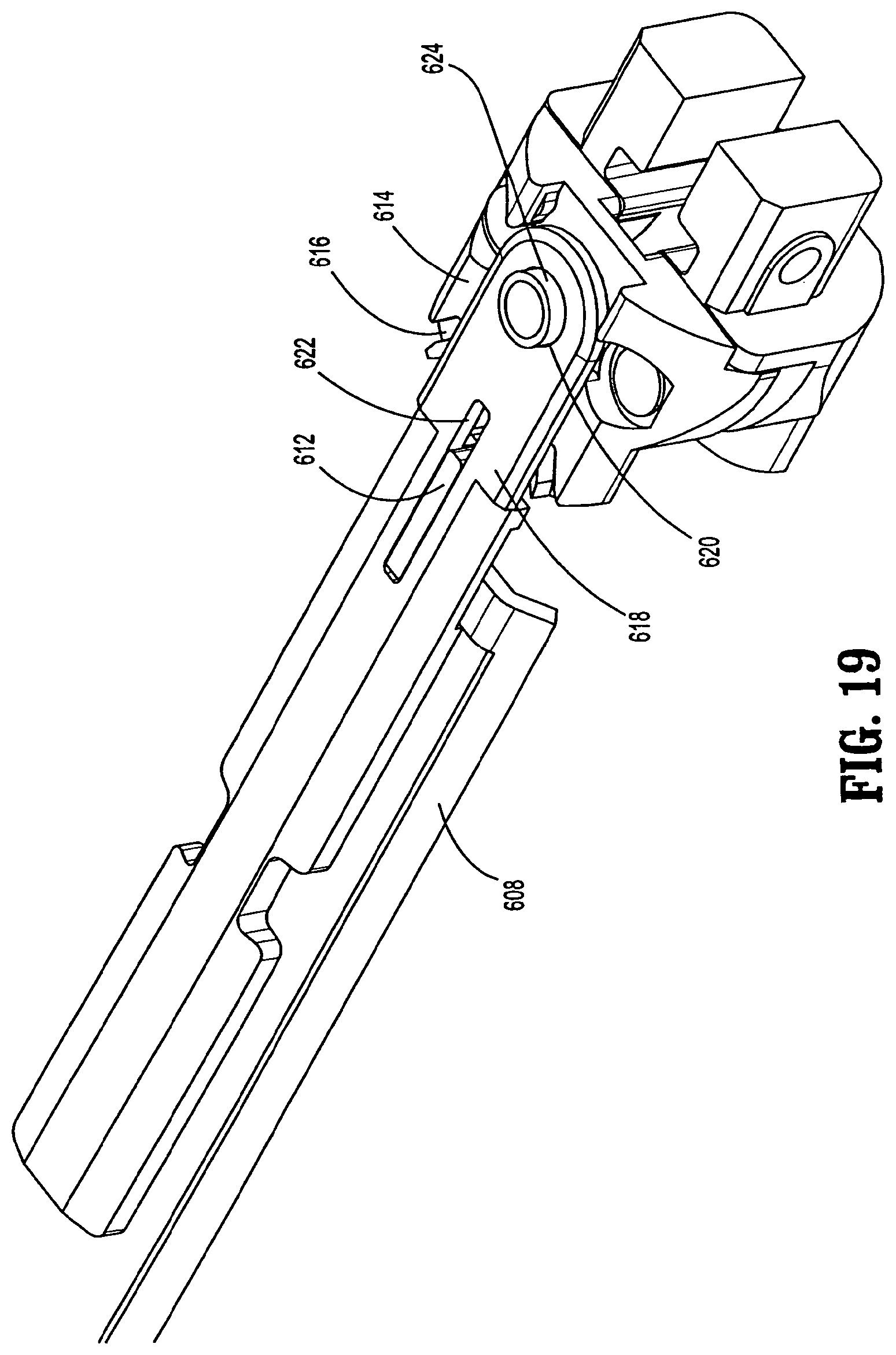
D00019

D00020

D00021

D00022

D00023

D00024

D00025

D00026

D00027

D00028
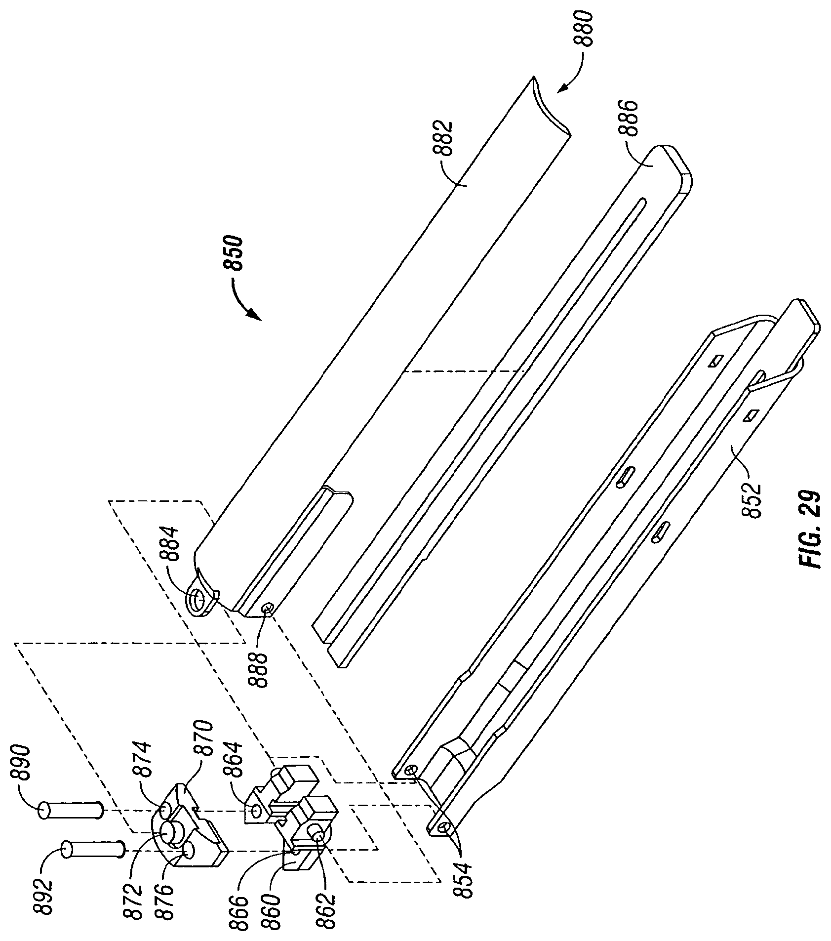
XML
uspto.report is an independent third-party trademark research tool that is not affiliated, endorsed, or sponsored by the United States Patent and Trademark Office (USPTO) or any other governmental organization. The information provided by uspto.report is based on publicly available data at the time of writing and is intended for informational purposes only.
While we strive to provide accurate and up-to-date information, we do not guarantee the accuracy, completeness, reliability, or suitability of the information displayed on this site. The use of this site is at your own risk. Any reliance you place on such information is therefore strictly at your own risk.
All official trademark data, including owner information, should be verified by visiting the official USPTO website at www.uspto.gov. This site is not intended to replace professional legal advice and should not be used as a substitute for consulting with a legal professional who is knowledgeable about trademark law.