Home appliance device
Akalan , et al.
U.S. patent number 10,697,692 [Application Number 15/363,026] was granted by the patent office on 2020-06-30 for home appliance device. This patent grant is currently assigned to BSH Hausgeraete GmbH. The grantee listed for this patent is BSH HAUSGERAETE GMBH. Invention is credited to Yigit Akalan, Ziya Arslankiray, Mehmet Ciyanoglu, Lars Dinter, Emre Emek, Ercan Engin, Hueseyin Sen, Tanzer Yildizgoecer.


View All Diagrams
| United States Patent | 10,697,692 |
| Akalan , et al. | June 30, 2020 |
Home appliance device
Abstract
For the purpose of improving efficiency, a home appliance device, in particular a home chiller appliance device, is proposed. The device includes at least one panel for at least partly covering an opening of a machine compartment; and a connection unit for connecting the panel; the panel comprising at least one panel module which has at least one fin, at least one first fin mounting element and at least one second fin mounting element for mounting the at least one fin, the connection unit comprising at least one connection element for connecting the at least one panel module, and wherein the connection element is movable with respect to the first fin mounting element and the second fin mounting element in a lengthwise direction of the panel in at least one pre-assembled state of the panel.
| Inventors: | Akalan; Yigit (Tekirdag, TR), Arslankiray; Ziya (Tekirdag, TR), Ciyanoglu; Mehmet (Istanbul, TR), Dinter; Lars (Munich, DE), Emek; Emre (Istanbul, TR), Engin; Ercan (Tekirdag, TR), Sen; Hueseyin (Tekirdag, TR), Yildizgoecer; Tanzer (Tekirdag, TR) | ||||||||||
|---|---|---|---|---|---|---|---|---|---|---|---|
| Applicant: |
|
||||||||||
| Assignee: | BSH Hausgeraete GmbH (Munich,
DE) |
||||||||||
| Family ID: | 60327211 | ||||||||||
| Appl. No.: | 15/363,026 | ||||||||||
| Filed: | November 29, 2016 |
Prior Publication Data
| Document Identifier | Publication Date | |
|---|---|---|
| US 20180149407 A1 | May 31, 2018 | |
| Current U.S. Class: | 1/1 |
| Current CPC Class: | F25D 23/003 (20130101); F25D 23/028 (20130101); F25D 2323/0021 (20130101); F25D 23/006 (20130101) |
| Current International Class: | F25D 23/02 (20060101); F25D 23/00 (20060101) |
| Field of Search: | ;312/401,405,265.5,265.6 ;62/440 |
References Cited [Referenced By]
U.S. Patent Documents
| 3912349 | October 1975 | Hoetker |
| 4128287 | December 1978 | Loch |
| 4932224 | June 1990 | Katterhenry |
| 4970874 | November 1990 | Solak |
| 5245841 | September 1993 | Paul |
| 5613747 | March 1997 | Becker |
| 6036292 | March 2000 | Mandel |
| 2004/0189164 | September 2004 | Hwang |
Attorney, Agent or Firm: Greenberg; Laurence A. Stemer; Werner H. Locher; Ralph E.
Claims
The invention claimed is:
1. A home appliance device comprising: at least one panel for at least partly covering an opening of a machine compartment; and a connection unit for connecting the panel; the panel comprising at least one panel module which has at least one fin, at least one first fin mounting element and at least one second fin mounting element for mounting the at least one fin, the connection unit comprising at least one connection element extending in a direction parallel to a lengthwise direction of the at least one panel for connecting the at least one panel module, and wherein the connection element is movable with respect to the first fin mounting element and the second fin mounting element in the lengthwise direction of the panel in at least one pre-assembled state of the panel.
2. The home appliance device according to claim 1, the connection element having at least one guiding element; the first fin mounting element and the second fin mounting element each comprising at least one corresponding guiding element respectively cooperating with the guiding element of the connection unit at least in an assembled state.
3. The home appliance device according to claim 1, the panel module comprising at least one fin reinforcement element, which reinforces the fin at least in a direction that is perpendicular to the lengthwise direction and is connected to at least one of the fin mounting elements by means of the connection unit.
4. The home appliance device according to claim 1, the panel module comprising at least one air separator, which separates an air flow through the panel and is connected to at least one of the fin mounting elements by means of the connection unit.
5. The home appliance device according to claim 1, the panel comprising at least one cover element, which at least partly covers a machine component and which is connected to at least one of the fin mounting elements by means of the connection unit.
6. The home appliance device according to claim 5, the cover element at least partly embodying the panel module.
7. The home appliance device according to claim 5, the cover element being at least partly implemented integrally with at least one fin mounting element.
8. The home appliance device according to claim 1, further comprising at least one further panel module, which is connected to the panel module by means of the connection unit.
9. The home appliance device according to claim 8, the panel comprising at least one cover element, which covers at least partly a machine component and which embodies at least partly the panel module and at least partly the further panel module.
10. A home appliance device according to claim 1, wherein the connection unit is configured for interconnecting the panel toollessly with a housing of the home appliance device in a form-fit and/or force-fit manner, the connection unit having a release element, which is accessible through the panel and via which a connection of the panel and the housing is releasable.
11. A home appliance device according to claim 10, wherein the panel has a first panel plane and a second panel plane, which are connected to each other by means of the connection unit.
12. The home appliance device according to claim 11, the connection unit comprising an adjustment unit for adjusting an offset between the first panel plane and the second panel plane.
13. A home appliance device according to claim 10, wherein the at least one panel comprises at least two or a plurality of panel modules which have at least one or at least two or a plurality of fin/s, at least one first fin mounting element and at least one second fin mounting element for mounting at least one or at least two or a plurality of fin/s, the connection unit comprising at least one connection element for connecting the at least two panel modules to each other.
14. A home appliance comprising at least one home appliance device according to claim 10.
15. A method for assembling a home appliance device-according to claim 10, comprising at least one pre-assembly step, wherein at least one connection element is moved with respect to at least one first fin mounting element and at least one second fin mounting element in a lengthwise direction of the panel for connecting the panel.
16. A home appliance device according to claim 1, wherein the panel has a first panel plane and a second panel plane, which are connected to each other by means of the connection unit.
17. The home appliance device according to claim 16, the connection unit comprising an adjustment unit for adjusting an offset between the first panel plane and the second panel plane.
18. A home appliance device according to claim 1, wherein the at least one panel has at least two or a plurality of panel modules which have at least one or at least two or a plurality of fin/s, at least one first fin mounting element and at least one second fin mounting element for mounting at least one or at least two or a plurality of fin/s, the connection unit comprising at least one connection element for connecting the at least two panel modules to each other.
19. A home appliance comprising at least one home appliance device according to claim 1.
20. A method for assembling a home appliance device-according to claim 1, comprising at least one pre-assembly step, wherein at least one connection element is moved with respect to at least one first fin mounting element and at least one second fin mounting element in a lengthwise direction of the panel for connecting the panel.
Description
BACKGROUND OF THE INVENTION
Field of the Invention
The invention relates to a home appliance device, in particular a home chiller appliance device and a method for assembling a home appliance device.
From the prior art a home appliance device is known which comprises at least one panel for at least partly covering an opening of a machine room.
SUMMARY OF THE INVENTION
An objective of the invention is, in particular, to provide a home appliance device with improved characteristics regarding efficiency. This objective is achieved, according to the claimed invention. Further implementations and further developments of the invention may be gathered from the dependent claims.
A home appliance device, in particular a home chiller appliance device, is proposed, comprising: at least one, preferably at least two and advantageously a plurality of panel/s, for at least partly and preferably at least mostly covering an opening of a machine compartment; and a connection unit for connecting the at least one panel, the panel comprising at least one or at least two or a plurality of panel module/s which has/have at least one or at least two or a plurality of fin/s, at least one first fin mounting element and at least one second fin mounting element for mounting at least one or at least two or a plurality of fin/s, the connection unit comprising at least one connection element for connecting the at least one panel module, the connecting element being movable with respect to the first fin mounting element and the fin second mounting element in a lengthwise direction of the panel in at least one pre-assembled state of the panel.
By means of the invention in particular an efficiency of the home appliance device can be improved. Advantageously, an efficiency of an assembly and/or disassembly can be improved. In particular, an assembly and or disassembly can be carried out toollessly. In particular, a cooling performance can be improved. In addition, a design of the home appliance device may be improved. Preferably by means of the connection unit screws used for assembly may be covered in an efficient manner. In particular, by use of the panel modules the panel may be implemented mirror-invertedly in a simple manner, in particular if an installation side of a home appliance door hinge has to be changed. Furthermore, a stability of the home appliance device may be improved.
In this context, "configured" is in particular to mean specifically programmed, designed and/or equipped. By an object being configured for a certain function is in particular to be understood that the object implements and/or fulfills said certain function in at least one application state and/or operating state. By a "home appliance device" is in particular to be understood at least a portion, preferably a sub-assembly group, of a home appliance. The home appliance is in particular provided for storing and preferably tempering victuals, such as beverages, meat, fish, vegetables, fruits, milk and/or dairy products, in at least one operating state, advantageously for the purpose of enhancing a keepability of the stored victuals. Advantageously, the home appliance is embodied as a home chiller appliance, which is in at least one operating state configured for cooling victuals. The home chiller appliance could in particular be embodied as a climate cabinet, an ice-box, a refrigerator, a freezer, a refrigerator-freezer combination and/or a wine cooler. However, the home appliance could also be embodied as a home appliance for warming and in particular for cooking victuals, e.g. an oven, a steamer and/or a microwave.
In case the home appliance device comprises at least two or a plurality of panels as deemed advantageous by someone skilled in the art, the panels may be embodied at least substantially equivalently or at least substantially differently, as compared to each other. The panel covers at least partly or at least mostly the opening of the machine compartment of the home appliance device, in particular viewed in a direction which is at least substantially perpendicular to a lengthwise direction of the panel. The term "at least mostly" with reference to an object is in particular to mean by more than 50%, preferably more than 65%, further preferably more than 80% and advantageously more than 95% of an object, in particular a surface area and/or a volume and/or a mass of the object. In this context, "at least substantially perpendicular" is in particular to be understood as an orientation of a direction with respect to a reference direction, in particular in a plane, wherein the direction and the reference direction include an angle of 90.degree., the orientation in particular having a deviation of less than 15.degree., advantageously of less than 10.degree. and particularly advantageously of less than 2.degree.. The lengthwise direction of the panel is in particular defined by a main extension of the panel. A "main extension" of an object is, in particular, to be understood as a largest extension of an imaginary rectangular cuboid which only just entirely encloses the object and which preferably extends through a geometric center of the object.
In this context, a "machine compartment" is in particular to be understood as a compartment of the home appliance device which is in particular configured for accommodating components, in particular machine components, of the home appliance device. The machine compartment accommodates, in particular at least partly accommodates, a refrigerant cycle of the home appliance device. The refrigerant cycle may comprise in particular a compressor, a condenser, a dryer, an expansion device, an evaporator, a fan unit and/or a heat exchanger, which may at least partly be accommodated inside the machine compartment. The machine compartment may accommodate in particular a door opening unit of the home appliance device, which is configured for opening a home appliance door of the home appliance device. The machine compartment may accommodate in particular a water filter of the home appliance device, which is preferably configured for supplying water. The machine compartment may comprise an opening configured for air circulation, preferably into and/or out of the machine compartment. In particular, in an installation position of the home appliance device, the machine compartment is arranged in a bottom region of the home appliance device. The machine compartment may in particular be different from a storage compartment of the home appliance device, which is configured for storing victuals.
The connection element may in particular be an elongate element. In this context, an "elongate element" is in particular an element having a main extension which is at least three times or at least five times or at least ten times greater than a maximal extension perpendicularly to the main extension. Additionally, the connection unit may comprise an additional connection element, which may in particular be implemented at least substantially equivalently to the connection element. The connection unit may comprise in particular at least one further connection element. The further connection element may in particular be arranged opposite the connection element. A main extension of the connection element and a main extension of the additional connection element, in particular together, are at most equal to and in particular smaller than a main extension of the further connection element. The connection element may connect at least two or a plurality of further panel modules, in particular at least three and for example at least five panel modules of the at least one panel to each other.
The fin may in particular be configured for redirecting air, which is in particular sucked into and/or blown out of the machine compartment, from a direction which is at least substantially perpendicular to the main extension of the fin into a direction which is at least substantially askew with respect to a main extension of the panel. In this context, a direction being "at least substantially askew" is in particular to be understood to differ at least substantially from being parallel and/or from being perpendicular. In this context, "at least substantially parallel" is in particular to be understood as an orientation of a direction with respect to a reference direction, in particular in a plane, wherein the direction and the reference direction include an angle of 0.degree., the orientation in particular having a deviation of less than 15.degree., advantageously of less than 10.degree. and particularly advantageously of less than 2.degree.. The fin may comprise in particular at least one angular deflection for deflecting air, which is in particular at least substantially perpendicular to a main extension of the fin. The fin may extend in particular at least substantially parallel to the lengthwise direction of the panel. In particular, at least two fins, which are stacked and spaced apart from one another, embody an air channel. Further the fin may comprise a fixing protrusion and/or a fixing recess which is at least configured for fixing the fin to at least one further component of the panel module. The fin may comprise in particular at least one or at least two or a plurality of blocking recess/es. The blocking recess is may in particular be configured for blocking a movement of the fin with respect to at least one further component of the panel module.
The first fin mounting element and the second fin mounting element may in particular be implemented mirror-invertedly to one another. In the following the first fin mounting element is described in detail. The description regarding the first fin mounting element may be applied to the second fin mount element. The fin mounting elements may be configured for mounting the fins in a form-fit and/or force-fit manner. By the term "in a force-fit and/or form-fit manner" is in particular to be understood connected, preferably releasably connected, wherein a holding force between two structural components is preferably transferred via a geometric engagement of the structural components with each other, and/or preferably via a friction force acting between the structural components. Alternatively or additionally a connection may be provided by substance-to-substance bond, preferably an adhesive and/or cohesive connection. For mounting the at least one fin, the first fin mounting element may comprise in particular at least one mounting profile which is configured for receiving the at least one fin. The mounting profile may correspond in particular to the shape of the at least one fin. In particular, the mounting profile is shaped correspondingly to at least two, in particular a plurality of fins which are stacked and/or spaced apart from each other, in particular in a direction which is at least substantially perpendicular to the lengthwise direction of the panel. The mounting profile may comprise in particular at least one or at least two or a plurality, which is in particular equal to the number of fins, of corresponding angular deflection/s corresponding to the angular deflection of preferably respective at least one or the at least two or the plurality of fins. In particular, the mounting profile may comprise at least one or at least two or a plurality, which is in particular equal to the number of fins, of fixing edge/s corresponding to the fixing edge of the at least one fin. The fin mounting element may be made of plastic.
Further, it is proposed that the connection element and/or the additional connection element may have at least one guiding element, and the first fin mounting element and the second fin mounting element each comprise at least one corresponding guiding element respectively cooperating with the guiding element of the connection unit at least in an assembled state. In particular, the further connection element may have at least one further guiding element, and the first fin mounting element and the second fin mounting element each may comprise at least one further corresponding guiding element respectively cooperating with the further guiding element of the further connection unit at least in an assembled state. In particular, the guiding element of the connection element, the additional connection element and/or the further connection element and the corresponding guiding elements and/or further corresponding guiding elements of the fin mounting elements may be connected to each other in particular in a form-fit and/or force-fit manner. As a result, in particular an assembly of the panel module can be simplified.
In addition, it is proposed that the panel module may comprise at least one or at least two or a plurality of fin reinforcement element/s, which reinforce/s the at least one fin at least in a direction that is perpendicular to the lengthwise direction of the panel, and which is/are respectively connected to at least one of the fin mounting elements by means of the connection unit. For connecting the at least one fin, the fin reinforcement element may comprise in particular at least one reinforcement profile which is configured for receiving the at least one fin. The reinforcement profile corresponds in particular to the shape of the at least one fin. In particular, the mounting profile may be formed correspondingly to at least two, in particular a plurality of fins which are stacked and/or spaced apart from each other preferably in a direction which is at least substantially perpendicular to the lengthwise direction of the panel. The reinforcement profile may comprise in particular at least one or at least two or a plurality, which is in particular equal to the number of fins, of corresponding angular deflection/s, which correspond/s to the angular deflection of preferably the respective at least one, preferably at least two and advantageously the plurality of fins. In particular, the reinforcement profile may comprise at least one or at least two or a plurality, which is in particular equal to the number of fins, fixing edge/s which correspond/s to the fixing edge of the at least one fin. In addition the reinforcement profile may comprise at least one or at least two or a plurality, which is in particular equal to the number of fins, blocking protrusion/s which corresponds to blocking recess/es of the at least one fin. The blocking protrusion and the blocking recess of the fin may cooperate with each other for blocking a movement of the fin with respect to the fin reinforcement element. As a result, a stability of the fins can be improved. In particular, the fins can be implemented in particular as thin fins as they are supported by the fin reinforcement element. The fin reinforcement element may in particular be made of plastic.
For the purpose of connecting the fin reinforcement element in a simple manner, it is proposed that the fin reinforcement element may comprise at least one corresponding guiding element, which cooperates with the guiding element and/or the additional guiding element of the connection unit, in particular of the connection element, at least in an assembled state. In particular, the fin reinforcement element may comprise at least one further corresponding guiding element, which cooperates with the further guiding element of the connection unit, in particular the connection element, at least in an assembled state.
Furthermore, it is proposed that the panel module may comprise at least one air separator, which divides an air flow through the panel and is connected to at least one of the fin mounting elements by means of the connection unit. The air separator may preferably be made of plastic. For connecting the at least one fin, the air separator may comprise in particular at least one separation profile which is configured for receiving the at least one fin. The separation profile may correspond in particular to a shape of the at least one fin. In particular, the separation profile is shaped correspondingly to at least two, in particular a plurality of fins which are stacked and/or spaced apart from each other in particular in a direction which is at least substantially perpendicular to the lengthwise direction of the panel. The separation profile may comprise in particular at least one or at least two or a plurality, which is in particular equal to the number of fins, of corresponding angular deflection/s, which correspond/s to the angular deflection of preferably the respective at least one or the at least two or the plurality of fins. The air separator may comprise in particular at least one corresponding guiding element, which cooperates with the guiding element and/or the additional guiding element of the connection unit, in particular of the connection element, at least in an assembled state. In particular, the air separator may comprise at least one further corresponding guiding element, which cooperates with the further guiding element of the connection unit, in particular of the connection element, at least in an assembled state. It is conceivable that the air separator, the fin reinforcement element and/or the fin mounting element may be implemented integrally with one another. In this context, the term "a first object and a second object being at least partly implemented integrally with one another" is in particular to mean that at least one portion of the first object and at least one portion of the second object are implemented integrally with each other. "Implemented integrally" is in particular to mean, in this context, connected at least by substance-to-substance bond, e.g. by a welding process, an adhesive bonding, an injection-molding process and/or by another process that is deemed expedient by a person having ordinary skill in the art. In particular, "implemented integrally" could in particular mean made of one piece. "Made of one piece" is, in particular, to mean, in this context, manufactured from one single piece, e.g. by production from one single cast and/or by manufacturing in a one-component or multi-component injection-molding process, and advantageously from a single blank. As a result of this, the air separator can be implemented in the panel.
It is further proposed that, the panel may comprise at least one cover element, which at least partly or at least mostly or entirely covers a machine component and which is connected to at least one of the fin mounting elements by means of the connection unit. The cover element may in particular be embodied as a cover of a door opening unit of the home appliance device. The door opening unit is configured for opening a home appliance door of the home appliance device. The door opening unit may in particular be arranged inside, preferably centrally inside, the machine compartment. The opening device extends in particular at least partly through the cover element. Alternatively or additionally the cover element can be embodied as a hinge cover which at least partly covers a hinge of a home appliance door of the home appliance device and/or which the hinge for the home appliance door is at least partly fixed to. It is conceivable that the cover element is embodied as a water filter cover. The cover element may be made of plastic. The cover element may comprise in particular at least one corresponding guiding element, which cooperates with the guiding element and/or the additional guiding element of the connection unit, in particular of the connection element, at least in an assembled state. In particular, the cover element may comprise at least one further corresponding guiding element, which cooperates with the further guiding element of the connection unit, in particular of the connection element, at least in an assembled state. As a result of this, a uniform design of the panel can be achieved.
In a further implementation of the invention it is proposed that the cover element at least partly or at least mostly or entirely embodies the panel module. Further the cover element could be at least partly implemented integrally with the air separator, the fin reinforcement element and/or the fin mounting element. As a result of this, in particular the cover element may be implemented in the panel in a simple manner.
It is further proposed that the home appliance device may comprise at least one further panel module, which is connected to the panel module by means of the connection unit, in particular by means of the connection element, the additional connection element and/or the further connection element. As a result of this, in particular a plurality of panel modules may be connected to each other in a simple manner.
In a further implementation of the invention it is proposed that the panel may comprise at least one cover element, in particular the aforementioned cover element, which covers at least partly a machine component, which is in particular accommodated inside the machine compartment, and which embodies at least partly the panel module and at least partly the further panel module. In particular, the cover element may at least partly be implemented integrally with at least one fin mounting element of the panel module and at least one fin mounting element of the further panel module. As a result of this, in particular efficiency of the home appliance device, in particular assembly efficiency, can be improved.
In another aspect of the invention, which can in particular be considered in combination with as well as separately from other aspects of the invention, it is proposed that the connection unit is configured for connecting the panel toollessly to a housing of the home appliance device in a form-fit and/or force-fit manner. The connection unit may comprise in particular at least one or at least two or a plurality of interconnection element/s. The interconnection element may preferably be connected to the panel, in particular to a lateral side of the panel and in particular to the fin mounting element and/or the cover element, in particular via a screw fixation. The interconnection element may comprise at least one interconnection guiding element, which is in particular embodied as a pin. The interconnection element may further comprise in particular a preferably deformable snap element, which may be embodied as a snap hook. The interconnection element may in particular be implemented of one piece, e.g. as an injection-molded part. The interconnection element may be made of plastic. The connection unit may comprise in particular a corresponding interconnection element, which in particular cooperates with the interconnection element for interconnecting the panel to the housing. The corresponding interconnection element may in particular be fixed to the housing, in particular via a screw fixation. The corresponding interconnection element may in particular be connected to the housing, in particular to a lateral side of the housing. The corresponding interconnection element may comprise at least one or at least two or a plurality of corresponding interconnection guiding element/s. The corresponding interconnection guiding element may in particular be embodied as a rail. The interconnection element may comprise a corresponding snap element. The corresponding snap element may be embodied as a snap edge. The corresponding interconnection element may comprise in particular a deformation element, which may preferably be embodied as a guiding chamfer. The deformation element may be configured to deform the snap element of the interconnection element. The corresponding interconnection element may in particular be implemented of one piece, in particular as a stamped-and-bent part. The corresponding interconnection element may be made of metal. In particular, in an installed position, the snap element may be snapped into the corresponding snap element and may in particular be deformed by means of the deformation element such that it is wedged behind the corresponding snap element. As a result of this, in particular, the panel can be connected to the housing toollessly.
It is further proposed that the connection unit may comprise a release element, which is accessible through the panel and via which a connection is releasable implemented between the panel and the housing by means of the connection unit. In order to release the interconnection of the interconnection element and the corresponding interconnection element, the release element may be configured to be operated through the panel. When operated the release element may be configured to deform the snap element in order to release it from its wedged position behind the corresponding snap element. As a result of this, in particular a connection between the panel and the housing can be disassembled in a simple manner. The release element may be operatable through a gap between two neighboring fins, in particular from the outside of the home appliance device and/or in particular by using a standard tool such as a screw driver.
In another aspect of the invention, which can in particular be considered in combination with as well as separately from other aspects of the invention, it is proposed that the panel comprises a first panel plane and a second panel plane which are connected to each other by means of the connection unit. In particular the connection unit may comprise at least one adjustment unit for adjusting an offset of the first panel plane with respect to the second panel plane. The first panel plane may in particular be embodied at least partly by at least one or at least two or a plurality of panel modules. Further, the first panel plane may in particular be embodied at least partly by the connection unit, in particular the connection element, the further connection element and the additional connection element. The second panel plane may be embodied by a plate, in particular a metal plate. In particular the first panel plane may be offset with respect to the second panel plane. The connection unit may comprise in particular at least one adjustment unit. The adjustment unit may in particular be configured for adjusting an offset of the first panel plane with respect to the second panel plane. The adjustment unit may comprise at least one adjustment element. The adjustment element may in particular be embodied by the further connection element. The adjustment element may in particular be embodied as a slot. The adjustment unit may comprise at least one engagement element. The engagement element may correspond to the adjustment element and may cooperate with the adjustment element for adjusting the offset. The adjustment element may in particular be embodied by the second panel plane. The engagement element/s may preferably be connected to the guiding element/s by means of a screw connection. As a result of this, a flexibility of the panel can be improved. The panel can in particular be adjusted to different types of furniture housings for an installation of the home appliance device in a home appliance or a kitchen.
In another aspect of the invention, which can in particular be considered in combination with as well as separately from other aspects of the invention, a home appliance device is proposed, in particular a home chiller appliance device, comprising: at least one panel, for at least partly or at least mostly covering an opening of a machine compartment; and a connection unit for connecting the at least one panel, the panel comprising at least two or a plurality of panel modules which have at least one or at least two or a plurality of fin/s, at least one first fin mounting element and at least one second fin mounting element for mounting at least one or at least two or a plurality of fin/s, the connection unit comprising at least one connection element for connecting the at least two panel modules to each other.
A method for assembling a home appliance device comprising at least one pre-assembly step, wherein at least one connection element is moved with respect to at least one first fin mounting element and at least one second fin mounting element in a lengthwise direction of the panel at least for connecting a panel module. By this method, in particular an efficiency of the home appliance device can be improved.
Herein the home appliance device and the method for assembling a home appliance device are not to be limited to the application and implementation described above. In particular, for the purpose of fulfilling a functionality herein described, the home appliance device may comprise a number of respective elements, structural components and units that differs from the number mentioned herein. Furthermore, regarding the value ranges mentioned in this disclosure, values within the limits mentioned are to be understood to be also disclosed and to be used as applicable.
Further advantages may become apparent from the following description of the drawing. In the drawing an exemplary embodiment of the invention is shown. The drawing, the description and the claims contain a plurality of features in combination. The person having ordinary skill in the art will purposefully also consider the features separately and will find further expedient combinations.
If there is more than one specimen of a certain object, only one of these is given a reference numeral in the figures and in the description. The description of this specimen may be respectively transferred to the other specimens of the object accordingly.
BRIEF DESCRIPTION OF THE SEVERAL VIEWS OF THE DRAWING
FIG. 1 a home appliance comprising a home appliance device, in a schematic perspective view,
FIG. 2 a portion of the home appliance device, comprising a machine compartment, in a cross-sectional top view,
FIG. 3 a portion of the home appliance device, comprising a panel and a further panel, in a perspective view,
FIGS. 4A, 4B the panel in a pre-assembled state and in a disassembled state, in a perspective view,
FIGS. 5A, 5B, 6 a portion of the home appliance device, comprising a connection unit and the panel having a plurality of components, in multiple views,
FIGS. 7-10, 11A, 11B, 12A, 12B, 13, 14A, 14B, and 15-17 a portion of the home appliance device, comprising a connection unit and the panel having a plurality of components.
FIGS. 18A, 18B the further panel in a pre-assembled state and in a disassembled state, in a perspective view, and
FIGS. 19, 20A, 20B, 21-23, 24A and 24B a portion of the home appliance device, comprising the connection unit and the further panel comprising a plurality of components, in multiple views.
DETAILED DESCRIPTION OF THE INVENTION
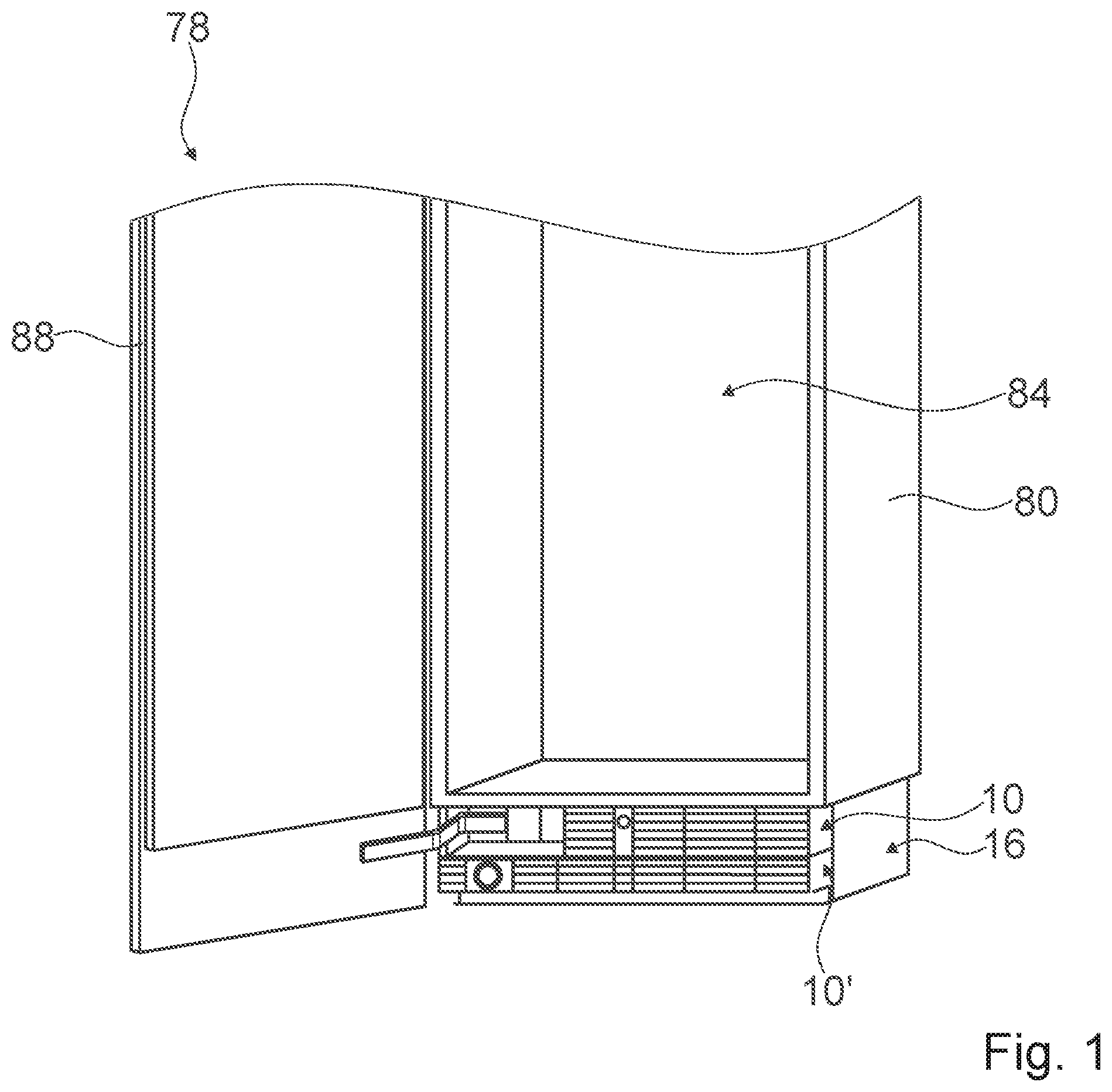
FIG. 1 shows a home appliance 78 comprising a home appliance device, in a schematic perspective view. The home appliance 78 is embodied as a refrigerator. The home appliance 78 could further be embodied as any other home appliance deemed advantageous by someone skilled in the art, e.g. a climate cabinet, an ice-box, a freezer, a wine-cooler and/or a refrigerator-freezer combination.
The home appliance device comprises a housing 80. The housing 80 comprises a storage compartment 84 which is configured for storing victuals. The home appliance device comprises a home appliance door 88. In a closed state, the home appliance door 88 closes the storage compartment 84.
The home appliance device comprises a machine compartment 16. In an installation position of the home appliance device, the machine compartment 16 is arranged at a bottom region of the home appliance device. Inside the machine compartment 16 further components of the home appliance device can be accommodated.
FIG. 2 shows a portion of the machine compartment 16 in a cross-sectional top view. The home appliance device comprises a refrigerant cycle 90. The refrigerant cycle 90 comprises a compressor 92, a condenser 94, a dryer 96, an expansion device 98, an evaporator 100, a fan unit 108 and/or a heat exchanger 102. The machine compartment 16 accommodates at least partly the refrigerant cycle 90, in particular the compressor 92, the condenser 94, the dryer 96, the expansion device 98, the evaporator 100, the fan unit 108 and/or the heat exchanger 102 of the home appliance device. The home appliance device comprises a door opening unit 104. The door opening unit 104 is configured for opening the home appliance door 88. The door opening unit 104 is at least partly accommodated inside the machine compartment 16. The home appliance device further comprises a water filter 106. The water filter 106 is configured for supplying water. The water filter 106 is accommodated inside the machine compartment 16.
The machine compartment 16 comprises an opening 14. In an installation position of the home appliance device, the opening 14 is arranged at a front of the home appliance device, in particular of the machine compartment 16. Through the opening 14 air can be exchanged between an environment of the home appliance device and the machine compartment 16. The air is used by the refrigerant cycle 90 for implementing refrigeration and/or for cooling of machine components inside the machine compartment 16.
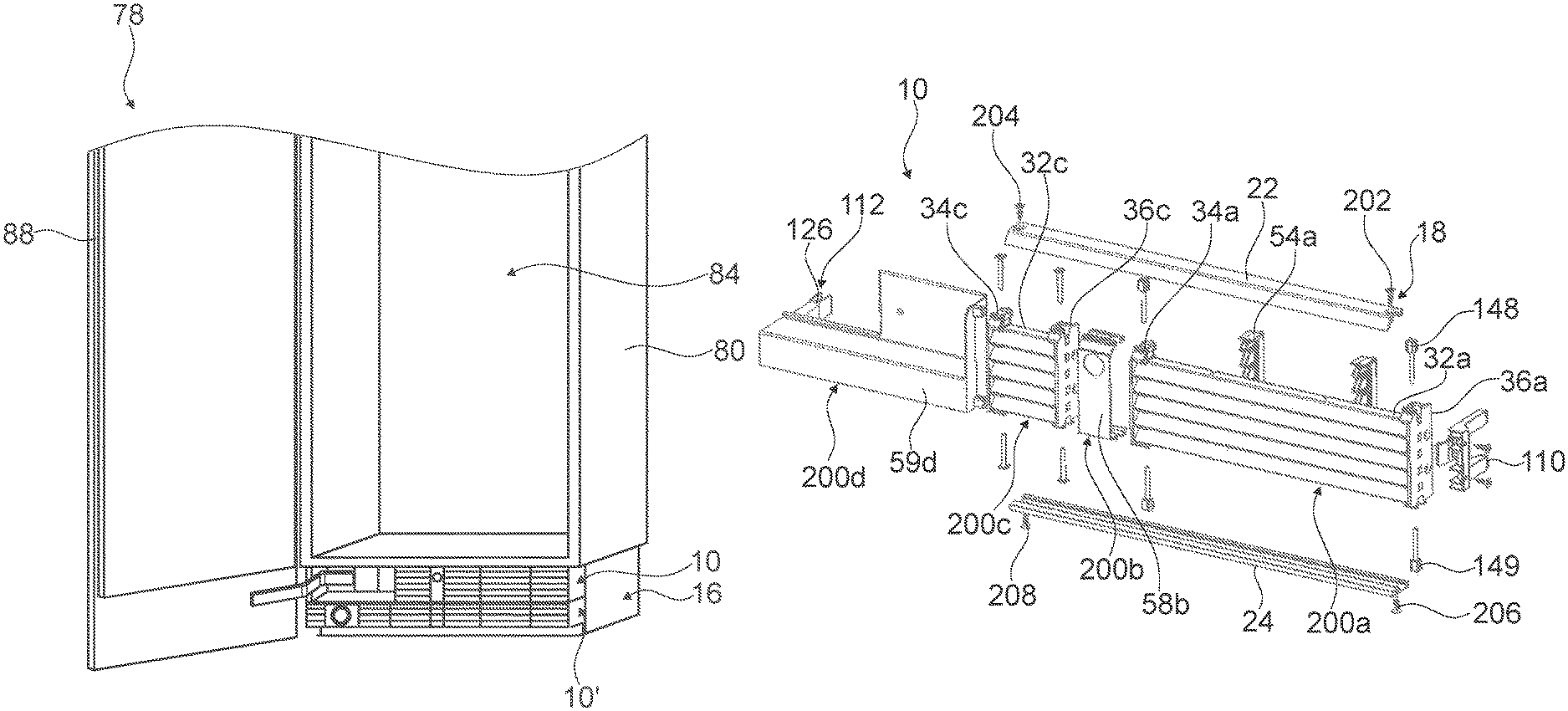
FIG. 3 shows a portion of the home appliance device in a perspective view. The home appliance device comprises at least one panel 10. In the present case the home appliance device comprises only one panel 10. It is conceivable that the home appliance device may comprise a differing number of panels 10 as deemed advantageous by someone skilled in the art.
FIGS. 4A and 4B show the panel 10 in a pre-assembled state and in a disassembled state. In the following description and in FIGS. 5 to 17 components of the panel 10, and in particular their interaction with further components of the home appliance device, are described in detail. Further the interaction of the components of the panel 10, in particular regarding an assembly and/or disassembly are described in detail.
The panel 10 at least partly covers the opening 14 of the machine compartment 16 (see FIG. 3). For connecting the panel 10, the home appliance device comprises a connection unit 18. In an installed state, the panel 10 is interconnected with the housing 80 of the home appliance device in a form-fit and/or force-fit manner by means of the connection unit 18. The interconnection of the panel 10 and the housing 80 can be carried out toollessly by means of the connection unit 18.
The connection unit 18 comprises at least one interconnection element 110. FIGS. 5A and 5B show the interconnection element 110 from different perspective views. In the present case the connection unit 18 comprises three such interconnection elements 110. It is conceivable that connection unit 18 may comprise a differing number of interconnection elements 110 as deemed advantageous by someone skilled in the art. The following description may be applied to further interconnection elements 110 accordingly.
The interconnection element 110 is connected to the panel 10, in particular via a screw fixation. The interconnection element 110 is fixed to a lateral side of the panel 10. The interconnection element 110 comprises two interconnection guiding elements 114 (see FIGS. 5A and 5B). For the sake of clarity, in the following description and in the drawings only one interconnection guiding element 114 is given a reference numeral and is described in detail. The interconnection guiding element 114 is embodied as a pin. The interconnection element 110 further comprises a snap element 116. The snap element 116 is deformable. The snap element 116 is embodied as a snap hook. The interconnection element 110 comprises a release element 62. The release element 62 is configured for releasing an interconnection, by means of the connection unit 18, between the panel 10 and the housing 80. The release element 62 is accessible through the panel 10. The interconnection element 110 is implemented of one piece. The interconnection element 110 is an injection-molded part. The interconnection element 110 is made of plastic.
The connection unit 18 comprises a corresponding interconnection element 118 (see FIG. 6). The corresponding interconnection element 118 corresponds to the interconnection element 110. The corresponding interconnection element 118 cooperates with the interconnection element 110 for interconnecting the panel 10 to the housing 80. The corresponding interconnection element 118 is fixed to the housing 80, in particular via a screw fixation. The corresponding interconnection element 118 is connected to the housing 80, in particular to a lateral side of the housing 80. The corresponding interconnection element 118 comprises two corresponding interconnection guiding elements 120. For the sake of clarity, in the following description and in the drawing only one corresponding interconnection guiding element 120 is given a reference numeral and is described in detail. The corresponding interconnection guiding element 120 is embodied as a rail. The interconnection element 118 comprises a corresponding snap element 122. The corresponding snap element 122 is not deformable. The corresponding snap element 122 is embodied as a snap edge. The corresponding interconnection element 118 comprises a deformation element 124. The deformation element 124 is embodied as a guiding chamfer. The corresponding interconnection element 118 is implemented in one piece. The corresponding interconnection element 118 is a stamped-and-bent part. The corresponding interconnection element 118 is made of metal.
For interconnecting the panel with the housing by means of the connection unit 18, the corresponding interconnection guiding element 118 cooperates with the interconnection guiding element 110 (see FIG. 7). The interconnection element 110 and the corresponding interconnection element 118 are moved towards each other, in particular in a direction that is at least substantially perpendicular to a lengthwise direction 38 of the panel 10. The lengthwise direction 38 is a main extension direction of the panel 10. The interconnection element 110 cooperates with the corresponding interconnection element 118. The interconnection guiding elements 114 engage into the corresponding interconnection guiding elements 120. The snap element 116 snaps into the corresponding snap element 122. The snap element 116 is deformed by the deformation element 124. The snap element 116 is wedged behind the corresponding snap element 122. In order to release the interconnection of the interconnection element 110 and the corresponding interconnection element 118, the release element 62 can be operated through the panel 10. By means of the release element 62 the snap element 116 is released from its wedged position behind the corresponding snap element 122.
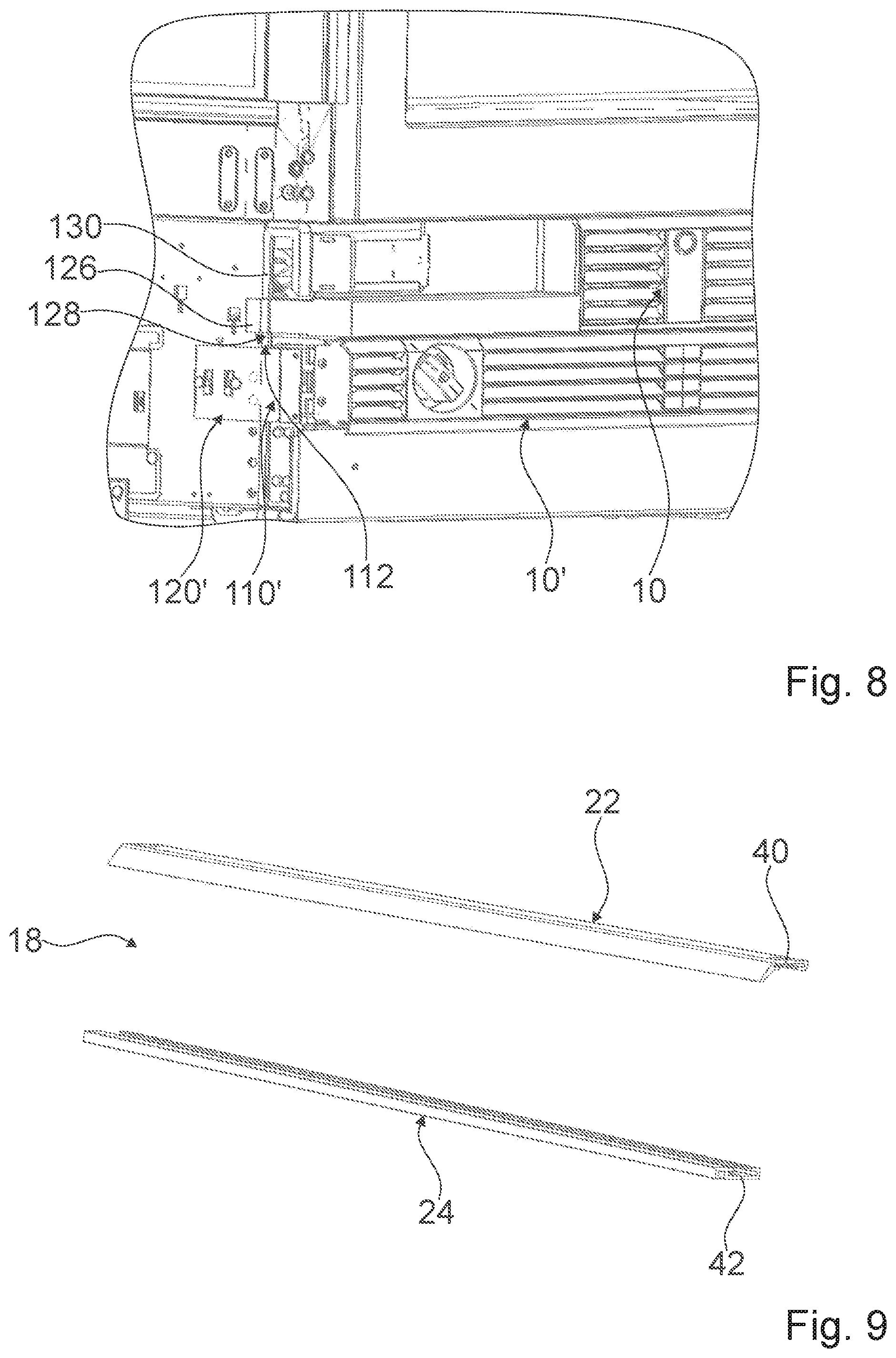
The connection unit 18 comprises a further interconnection element 112 (see FIGS. 4 and 8). The further interconnection element 112 is arranged at a further lateral side of the panel 10, in particular a lateral side which is arranged opposite the interconnection element 110. In the present case the further interconnection element 112 is implemented differently from the interconnection element 110. The further interconnection element 112 comprises a further snap element 126. The further snap element 126 is embodied as a gripper.
The connection unit 18 comprises a further corresponding interconnection element 128. The further corresponding interconnection element 128 is arranged at a further lateral side of the housing 80, in particular an opposite lateral side of the housing, in particular a lateral side which is located opposite the corresponding interconnection element 110. In the present case the further corresponding interconnection element 128 is implemented differently from the corresponding interconnection element 118. The further corresponding interconnection element 128 is implemented integrally with the housing 80. The further corresponding interconnection element 128 comprises a further corresponding snap element 130. The further corresponding snap element 130 is embodied by a bulge of the housing 80.
Further for interconnecting the panel 10 with the housing 80 by means of the connection unit 18, the further corresponding interconnection element 128 cooperates with the further interconnection element 112 for interconnecting the panel 10 with the housing 80. The further interconnection element 112 and the further corresponding interconnection element 128 are moved towards each other, in particular in a direction that is at least substantially perpendicular to the lengthwise direction 38 of the panel 10. The further interconnection element 112 cooperates with the further corresponding interconnection element 128. The further snap element 126 engages around the further corresponding snap element 130. The interconnection of the further interconnection element 110 and the further corresponding interconnection element 118 can be established by manually releasing the interconnection.
The panel 10 comprises at least one panel module 200a, 200b, 200c, 200d (see FIGS. 4A and 4B). In the present case the panel 10 comprises four panel modules 200a, 200b, 200c, 200d, namely in particular a first panel module 200a, a second panel module 200b, a third panel module 200c and a fourth panel module 200d. It is conceivable that the home appliance device may comprise a differing number of panel modules 200a, 200b, 200c, 200d, as deemed advantageous by someone skilled in the art.
The connection unit 18 comprises at least one connection element 22 (see FIGS. 4A, 4B and 9). The connection element 22 connects at least one panel module 200a, 200b, 200c, 200d of the home appliance device. Furthermore, the connection element 22 connects at least two panel modules 200a, 200b, 200c, 200d of the panel modules 200a, 200b, 200c, 200d to one another. In the present case the connection element 22 connects all of the panel modules 200a, 200b, 200c, 200d to each other. It is conceivable that the connection element 22 may connect a differing number of panel modules 200a, 200b, 200c, 200d to each other as deemed advantageous by someone skilled in the art. The connection element 22 comprises a guiding element 40, which is configured to cooperate with corresponding guiding elements of components of at least one of the panel modules 200a, 200b, 200c, 200d. The connection unit 18 comprises at least one further connection element 24 (see FIGS. 4B and 9). The further connection element 24 connects at least one panel module 200a, 200b, 200c, 200d of the home appliance device. Furthermore, the connection element 24 connects at least two panel modules 200a, 200b, 200c, 200d of the panel modules 200a, 200b, 200c, 200d to one another. In the present case the connection element 24 connects all of the panel modules 200a, 200b, 200c, 200d to each other. It is conceivable that the connection element 24 may connect a differing number of panel modules 200a, 200b, 200c, 200d to each other as deemed advantageous by someone skilled in the art. The further connection element 24 comprises a guiding element 42, which is configured to cooperate with further corresponding guiding elements of components of at least one of the panel modules 200a, 200b, 200c, 200d. The connection unit 18, in particular the connection element 22 and the further connection element 24 are fixed to further components of the home appliance device by means of a screw connection.
The panel module 200a has at least one fin 32a (see FIG. 10). In the present case the panel module 200a comprises five fins 32a. For the sake of clarity, in the following only one fin 32a is given a reference numeral and is described in detail. The following description may be applied to further fins 32a accordingly. It is conceivable that the panel module 200a may comprise a differing number of fins 32a as deemed advantageous by someone skilled in the art. The fin 32a comprises a main extension which is at least substantially parallel to a main extension of the panel 10. The fin 32a is embodied as an elongate sheet.
The fin 32a comprises an angular deflection 132a. In a pre-assembled state of the panel 10, the angular deflection 132a is at least substantially perpendicular to the lengthwise direction 38 of the panel 10.
The fin 32a comprises at least one connection recess 134a. In the present case the fin 32a comprises two connection recesses 134a. For the sake of clarity, in the following only one connection recess 134a is described in detail. The following description may be applied to the further connection recess 134a accordingly. It is conceivable that the fin 32a may comprise a differing number of connection recesses 134a as deemed advantageous by someone skilled in the art. The connection recess 134a is configured for connecting the fin 32a to further components of the panel module 200a. The connection recess 134a is positioned at an end section of the fin 32a. The two connection recesses 134a are respectively positioned at opposite end sections of the fin 32a.
Further the fin 32a comprises a fixing edge 136a. The fixing edge 136a is positioned in a vicinity of the angular deflection 132a. The fixing edge 136a is configured for fixing the fin 32a to further components of the panel module 200a. The fixing edge 136a extends at least substantially parallel to the lengthwise direction 38a of the panel 10.
The fin 32a comprises at least one blocking recess 138a. It is conceivable that the fin 32a may comprise a differing number of blocking recesses 138a as deemed advantageous by someone skilled in the art. The following description may be applied to further blocking recesses 138a accordingly. The blocking recess 138a is configured for blocking a movement of the fin 32a with respect to at least one further component of the panel module 200a. In particular, the number of blocking recesses 138a is equal to the number of fin reinforcement elements 54a of the panel module 200a.
The panel module 200a has at least one first fin mounting element 34a (see FIGS. 11A and 11B). The panel module 200a has at least one second fin mounting element 36a. The interconnection element 110 and/or the further interconnection element 112 may be fixed to the first fin mounting element 34a and/or the second fin mounting element 36a, in particular via a screw connection. In the present case the interconnection element 110 is fixed to the second fin mounting element 36a, in particular via a screw connection (see FIGS. 4A, 4B). The fin mounting elements 34a, 36a are configured for receiving the at least one, in particular five, fin/s 32a of the panel module 200a. The first fin mounting element 34a and the second fin mounting element 36a are embodied mirror-invertedly to one another. The fin mounting elements 34a, 36a each comprise at least one mounting profile 140a. The mounting profile 140a corresponds to the shape of the at least one fin 32a. The mounting profile 140a is shaped correspondingly to at least two, preferably five, fins 32a, which are stacked and/or spaced apart from each other in a direction which is at least substantially perpendicular to the lengthwise direction 38 of the panel 10. The mounting profile 140a comprises at least one corresponding angular deflection 142a. The corresponding angular deflection 142a corresponds to the angular deflection 132a of the at least one fin 32a. The mounting profile 140a comprises at least one corresponding fixing edge 144a. The corresponding fixing edge 144a corresponds to the fixing edge 136a of the at least one fin 32a.
The fin mounting elements 34a, 36a respectively comprise a connection hole 146a. The connection unit 18a comprises at least one corresponding connection pin 148a. The connection unit 18a comprises two corresponding connection pins 148a, 149a for each connection hole 146a. The corresponding connection pins 148a, 149a correspond to the connection hole 146a of the fin mounting elements 34a, 36a and to the connection recess 134a of the fin 32a. The connection pins 148a, 149a cooperate with the connection hole 146a of the fin mounting elements 34a, 36a, and the connection recess 134a of the fin 32a fixes the fin 32a to the fin mounting elements 34a, 36a, in particular in a form-fit and/or force-fit manner. The connection pin 148a is introduced into the connection hole 146a from a top side of the fin mounting elements 34a, 36a. The further connection pin 149a is introduced into the connection hole 146a from a bottom side of the fin mounting elements 34a, 36a.
The fin mounting element 34a in FIG. 11A is used for the further panel 10' whereas the fin mounting element 34a in FIG. 11B is used for the panel 10. Whereas the connection hole 146a in FIG. 11B is embodied to be used for the connection pins 148a, 149a the connection hole 146a in FIG. 11A is embodied to be used with a screw. With the screw the connection elements 22, 24 will be fixed to the fin mounting element 34a of FIG. 11A.
The connection pins 148a, 149a comprise a pin head and a pin shaft. The pin head is larger in diameter than the pin shaft. The pin head comprises an opening into which screws 202, 204, 206, 208 (FIG. 4B) are screwed. The screws 202, 204, 206, 208 extend also through holes in the connection elements 22, 24. In this way the connection elements 22, 24 are fixed, namely screwed, to the connection pins 148a, 149a. Likewise screws 202', 204', 206', 208', 210', 212' are used to fix the connection elements 22', 24', 26' (FIG. 18B).
For connecting the fin 32a to the fin mounting elements 34a, 36a, the fin 32a is received by the mounting profile 140a (see FIGS. 12A and 12B). By means of the mounting profile 140a, the fin 32a is mounted to the first fin mounting element 34a, in particular in a form-fit manner. When mounting the fin 32a, the corresponding angular deflection 142a of the mounting profile 140a cooperates with the angular deflection 132a of the at least one fin 32a. When mounting the fin 32a, the corresponding fixing edge 144a of the mounting profile 140a cooperates with the fixing edge 136a of the at least one fin 32a. The fin mounting elements 34a, 36a each comprise a connection hole 146a. The connection hole 146a of the first mounting element 34a and the connection recess 134a are positioned congruently one above the other one. The connection pin 148a is pushed into the connection recess 134a and the connection hole 146a and connects the fin 32a to the fin mounting element 34a, 36a.
In at least one pre-assembled state the connection element 22 is movable with respect to the first fin mounting element 34a (see FIGS. 4A and 4B). In at least one pre-assembled state, the connection element 22 is movable with respect to the second fin mounting element 36a. The connection element 22 is movable along the lengthwise direction 38 of the panel 10 in at least one pre-assembled state. In at least one pre-assembled state, the further connection element 24a is movable with respect to the first fin mounting element 34a. In at least one pre-assembled state, the further connection element 24a is movable with respect to the second fin mounting element 36a. The further connection element 24a is movable in the lengthwise direction 38 of the panel 10 in at least one pre-assembled state.
The first fin mounting element 34a comprises a corresponding guiding element 50a (see FIGS. 11A and 11B). The corresponding guiding element 50a of the fin mounting element 34a corresponds to the guiding element 40a of the connection element 22. For connecting the fin mounting elements 34a, 36a to each other, the corresponding guiding element 50a of the fin mounting element 34a cooperates with the guiding element 40a of the connection element 22. The fin mounting element 34a comprises a further corresponding guiding element 52a. The further corresponding guiding element 52a of the fin mounting element 34a corresponds to the further guiding element 42a of the further connection element 24a.
For connecting the fin mounting elements 34a, 36a to each other, the corresponding guiding element 52a of the fin mounting element 34a cooperates with the further guiding element 42a of the further connection element 24a (see FIGS. 12A and 12B). When the corresponding connection pins 148a, 149a are introduced into the connection hole 146a, they are flush with the corresponding guiding element 50a and the further corresponding guiding element 52a. When the corresponding connection pins 148a, 149a are introduced into the connection hole 146a, they are fixed by means of the guiding element 40a and the further corresponding guiding element 52a of the connection unit 18.
The panel module 200a comprises at least one fin reinforcement element 54a (see FIG. 13). In the present case the panel module 200a comprises two fin reinforcement elements 54a. For the sake of clarity, in the following only one fin reinforcement element 54a is given a reference numeral and is described in detail. The following description may be applied to further fin reinforcement elements 54a accordingly. It is conceivable that the panel module 200a may comprise a differing number of fin reinforcement element 54a as deemed advantageous by someone skilled in the art. The fin reinforcement element 54a reinforces the fin 32a at least in a direction perpendicular to the lengthwise direction 38a of the panel 10a. The fin reinforcement element 54a comprises a reinforcement profile 150a. The reinforcement profile 150a is shaped at least substantially equivalently to the mounting profile 140a. The description regarding the mounting profile 140a, in particular of the elements of the mounting profile 140a, is respectively applicable to the reinforcement profile 150a. The reinforcement profile 150a corresponds to the shape of the at least one fin 32a. The reinforcement profile 150a is shaped correspondingly to at least five fins 32a, which are stacked and/or spaced apart from each other in a direction which is at least substantially perpendicular to the lengthwise direction 38 of the panel 10. The reinforcement profile 150a comprises at least one corresponding angular deflection 154a. The corresponding angular deflection 154a corresponds to the angular deflection 132a of the fin 32a. The reinforcement profile 150a comprises at least one corresponding fixing edge 156a. The corresponding fixing edge 156a corresponds to the fixing edge 136a of the fin 32a. In addition, the reinforcement profile 150a comprises a fixing protrusion 152a. The fixing protrusion 152a corresponds to the blocking recess 138a of the fin 32a.
For connecting the fin 32a to reinforcement element 54a, the fin 32a is received by the reinforcement profile 150a (see FIGS. 14A and 14B). By means of the reinforcement profile 150a, the fin 32a is connected to the reinforcement element 54a, in particular in a form-fit manner. When connecting the fin 32a, the corresponding angular deflection 154a of the reinforcement profile 150a cooperates with the angular deflection 132a of the at least one fin 32a. When connecting the fin 32a, the corresponding fixing edge 144a of the reinforcement profile 150a cooperates with the fixing edge 136a of the at least one fin 32a.
The fin reinforcement element 54a is connected to at least to one of the fin mounting elements 34a, 36a by means of the connection unit 18 (see FIGS. 4A and 4B). The fin reinforcement element 54a comprises a corresponding guiding element 158a (see FIG. 13). The corresponding guiding element 158a of the fin reinforcement element 54a corresponds to the guiding element 40 of the connection element 22. The corresponding guiding element 158a of the fin reinforcement element 54a cooperates with the guiding element 40 of the connection element 22 for connecting the fin reinforcement element 54a to at least one fin mounting element 34a, 36a. The fin reinforcement element 54a comprises a further corresponding guiding element 160a. The further corresponding guiding element 160a of the fin reinforcement element 54a corresponds to the further guiding element 42 of the further connection element 24. The further corresponding guiding element 160a of the fin reinforcement element 54a cooperates with the further guiding element 42 of the further connection element 24 for connecting the fin reinforcement element 54a to at least one fin mounting element 34a, 36a.
The following description of the further panel modules 200b, 200c, 200d is substantially limited to the differences of the panel modules, wherein regarding structural elements, features and functions that remain the same the description of the panel module 200a may be referred to. For distinguishing the implementations, the letter a of the reference numerals in the embodiment of the panel module 200a has been substituted by the letters b, c and d for the respective panel modules 200b, 200c and 200d of the panel 10. Regarding structural elements having the same denomination, in particular regarding structural elements having the same reference numerals, principally the drawing and/or the description of the embodiment regarding panel module 200a may be referred to.
The panel module 200b differs from the preceding implementation of the panel module 200a at least by a cover element 58b. The panel module 200b comprises a cover element 58b (see FIG. 15). In the present case the cover element 58b is a door assistance cover element. Alternatively or additionally the cover element 58b may be embodied as a cover for any other component of the machine compartment 16 as deemed advantageous by someone skilled in the art. The cover element 58b covers the door opening unit 104 at least partly. In the present case the cover element 58b entirely embodies the panel module 200b. It is also conceivable that the cover element 58b embodies at least partly the panel module 200b and at least partly the further panel modules 200a, 200c, 200d. The cover element 58b is connected to at least one of fin mounting elements 34a, 36a, 34c, 36c by means of the connection unit 18. The cover element 58b comprises a corresponding guiding element 176b. The corresponding guiding element 176b of the cover element 58b corresponds to the guiding element 40 of the connection element 22. The corresponding guiding element 176b of the cover element 58b cooperates with the guiding element 40 of the connection element 22 for connecting the cover element 58b to at least one fin mounting element 34a, 36a, 34c, 36c. The cover element 58b comprises a further corresponding guiding element 178b. The further corresponding guiding element 178b of the cover element 58b corresponds to the further guiding element 42 of the further connection element 24. The further corresponding guiding element 178b of the cover element 58b cooperates with the further guiding element 42 of the connection element 24 for connecting the cover element 58b to at least one fin mounting element 34b, 36b. Alternatively or additionally the cover may be at least partly implemented integrally with at least one fin mounting element 34a, 36a, 34c, 36c.
The panel module 200c differs from the aforementioned implementation of panel module 200a at least substantially by the implementation of at least one fin 32c of the panel module 200c. In the present case the fin 32c is shorter than the fin 32a. Further the fin 32c does not comprise a blocking recess. Due to the fact that the at least one fin 32 c is shorter, fin reinforcement elements such as the fin reinforcement elements 34a, 36a of the panel module 200a can be dispensed with in the case of panel module 200c. The fin 32c is mounted to a first fin mounting element 34c and a second fin mounting element 36c of the panel module 200c.
The panel module 200d differs from the preceding implementation of the panel module 200a at least by a cover element 59d (see FIG. 16). The panel module 200d comprises the cover element 59d. In the present case a further interconnection element 112 is implemented integrally with the cover element 58d. Alternatively the further interconnection element 112 of the connection unit 18 may be fixed to the cover element 59d, in particular via a screw connection. In the present case the cover element 59d is a hinge cover element. Alternatively or additionally the cover element 58d may be a cover for any other component of the machine compartment 16 as deemed advantageous by someone skilled in the art. The cover element 59d provides an opening for a hinge 180 of the home appliance door 88, which may be fixed to a housing of the home appliance device. The cover element 59d entirely embodies the panel module 200d. It is also conceivable that the cover element 59d embodies at least partly the panel module 200d and at least partly the further panel modules 200a, 200b, 200c.
The cover element 59d is connected to at least one of the fin mounting elements 34a, 36a 34c, 36c by means of the connection unit 18 (see FIGS. 4A, 4B and 7). In the present case the cover element 59d is connected to a fin mounting element 34c, 36c of the panel module 200c. The cover element 59d comprises at least one protrusion element 162d. The protrusion element 162d corresponds to a protrusion recess 164c of a fin mounting element 34c, 36c of the panel module 200c. Alternatively or additionally the cover element 59d may be at least partly implemented integrally with at least one fin mounting element 34c, 36c. The protrusion element 162d comprises an opening for a screw (screw not shown in FIG. 17). After the fins are inserted into the fin mounting element 34c and have been fixed via the pins 148, 149, the protrusion element 162d is inserted into a reception of the fin mounting element 34c. The connection element 22 will be placed on top of the fin mounting element 34c and will be fixed via the screw which is screwed into the opening of the protrusion element 162.
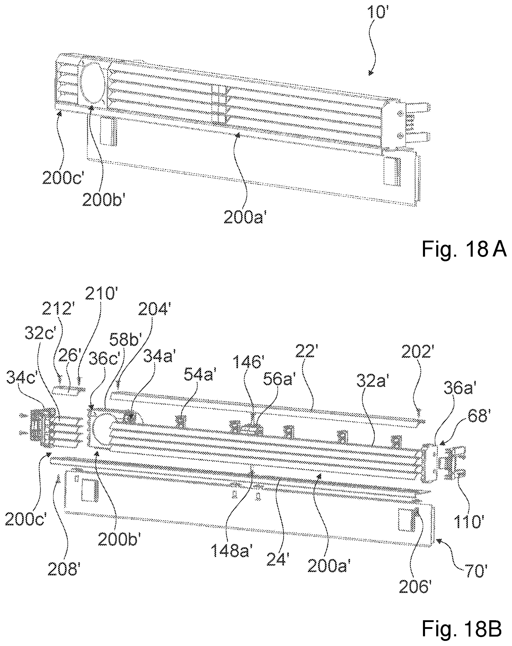
In the present case the home appliance device comprises at least one further panel 10'. FIGS. 18A and 18B show the further panel 10' in a pre-assembled state and in a disassembled state. In the following description and FIGS. 18 to 24 components of the further panel 10' and in particular their interaction with further components of the home appliance device are described in detail. Further the interaction of the components of the further panel 10', in particular regarding an assembly and/or disassembly, is described in detail.
The preceding description regarding the panel 10 may be at least partly, in particular entirely be respectively transferred to the further panel 10' accordingly. The panel 10' at least partly covers the opening 14 of the machine compartment 16 (see FIG. 3). The following description of the further panel 10' is substantially limited to the differences of the panels 10 and 10', wherein regarding structural elements, features and functions that remain the same the description of the panel 10 may be referred to. For distinguishing the different implementations, the reference numerals X in the embodiment of the panel 10 have been substituted by respective reference numerals X' for the respective panel 10'. Regarding structural elements having the same denomination, in particular regarding structural elements having the same reference numerals, principally the drawing and/or the description of the implementation of panel 10 may be referred to.
The panel 10' differs from the preceding implementation of the panel 10 at least by a number of panel modules (see FIGS. 18A and 18B). The panel 10' comprises at least one panel module 200a', 200b', 200c'. In the present case the panel 10' comprises three panel modules 200a', 200b', 200c', namely in particular a first panel module 200a', a second panel module 200b' and a third panel module 200c'. It is conceivable that the home appliance device may comprise a differing number of panel modules 200a', 200b', 200c' as deemed advantageous by someone skilled in the art.
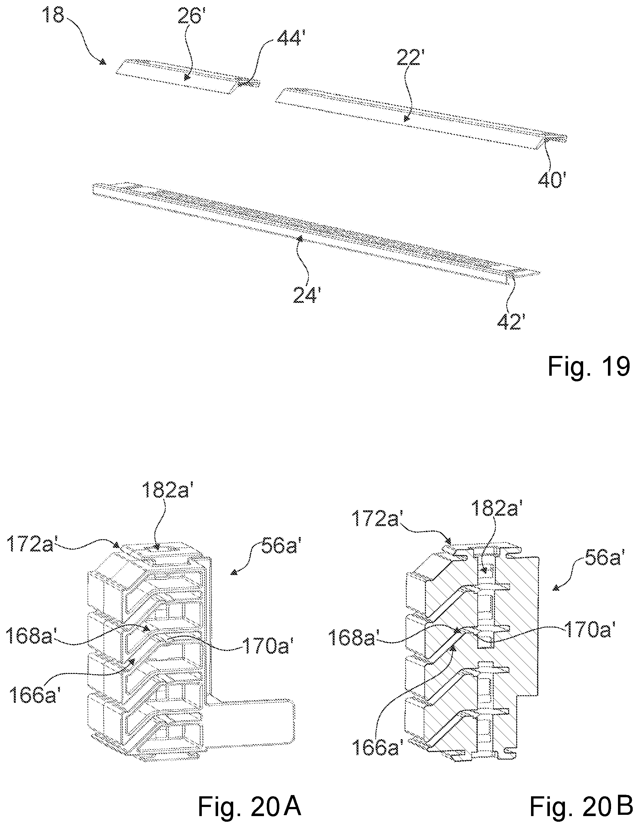
The connection unit 18 comprises at least one connection element 22' (see FIG. 19). The connection element 22' connects at least one of the panel modules 200a', 200b', 200c'. Furthermore, the connection element 22 connects at least two panel modules 200a', 200b', 200c' of the panel modules 200a', 200b', 200c' to one another. In the present case, the connection element 22' connects the panel module 200a' and the panel module 200b' to each other. The connection element 22' comprises a guiding element 40', which is configured to cooperate with corresponding guiding elements of components of at least one of the panel modules 200a', 200b', 200c'. The connection unit 18 comprises at least one additional connection element 26'. In the present case, the additional connection element 26' connects the panel module 200b' and the panel module 200c' to each other. The additional connection element 26' comprises a guiding element 44', which is configured to cooperate with the corresponding guiding elements of components of at least one of the panel modules 200a', 200b', 200c'. The connection unit 18 comprises at least one further connection element 24'. In the present case the connection element 24' connects the panel modules 200a', 200b', 200c' to each other. The further connection element 24' comprises a guiding element 42' which is configured to cooperate with further corresponding guiding elements of components of at least one of the panel modules 200a, 200b, 200c, 200d. In the present case, at least the connection element 22' and/or the additional connection element 26' is embodied differently from the connection element 22. A length of the connection element 22' and/or a length of the additional connection element 26' is shorter than the length of the further connection element 24'. The connection unit 18', in particular the connection elements 22', 24', 26' are fixed to further components of the home appliance device by means of a screw connection.
The panel module 200a' has at least one fin 32a'. In the present case the first module comprises four such fins 32a'. The fin 32a' comprises at least one connection recess 134a'. In the present case the fin 32a' comprises three connection recesses 134a'. The two connection recesses 134a' are positioned at opposite ending section of the fin 32a'. At least one of the connection recesses 134a' is/are positioned between an end section, in particular in a center of the fin 32a'.
In an additional or alternative implementation of the panel module 200a, the panel module 200a' comprises at least one air separator 56a' (see FIGS. 20A, 20B and 21). The air separator 56a' separates an air flow through the panel 10'. The air separator 56a' comprises a separation profile 166a'. The separation profile 166a' is shaped at least substantially equivalently to the mounting profile 140a. The description regarding the mounting profile 140a, in particular of the elements of the mounting profile 140a, preferably the corresponding fixing edge 144a, is applicable to the separation profile 166a'. The shape of the separation profile 166a' corresponds to the shape of the at least one fin 32a'. The separation profile 166a' is shaped correspondingly to at least four fins 32a', which are stacked and/or spaced apart from each other in a direction which is at least substantially perpendicular to a lengthwise direction 38' of the panel 10'. The separation profile 166a' comprises at least one corresponding angular deflection 168a'. The corresponding angular deflection 168a' corresponds to an angular deflection 132a' of the at least one fin 32a'. The separation profile 166a' comprises at least one corresponding fixing edge 170a'. The corresponding fixing edge 170a' corresponds to a fixing edge 136a' of the at least one fin 32a'.
The panel module 200a' comprises at least one first fin mounting element 34a' (see FIGS. 18A and 18B). The panel module 200a' comprises at least one second fin mounting element 36a'. In the present case of the panel module 200a', the connection unit 18 comprises two interconnection elements 110'. The interconnection element 110 is fixed to the second fin mounting element 36a'.
The panel module 200a' comprises at least one fin reinforcement element 54a'. The fin reinforcement element 54a' is embodied equivalently to the fin reinforcement element 54a. In the present case the panel module 200a' comprises five fin reinforcement elements 54a'.
For fixing the fin 32a' to the air separator 56a' the fin 32a' is received by the separation profile 166a'. By means of the separation profile 166a', the fin 32a' is fixed to the air separator 56a', in particular in a form-fit manner. During fixing of the fin 32a' the corresponding angular deflection 168a' of separation profile 166a' cooperates with an angular deflection 132a' of the at least one fin 32'a. When fixing the fin 32a', the corresponding fixing edge 170a' of the separation profile 166a' cooperates with the fixing edge 136a' of the fin 32a'. The separation profile 166a' comprise a connection hole 182a'. The connection hole 182a' of the air separator 56a' and the connection recess 134a' of the fins 32a' are positioned congruently on top of each other. A connection pin 148' is pushed into the connection recess 134a' and the connection hole 182a', connecting the fin 32a' to the air separator 56a'.
The air separator 56a' is connected to the at least one fin mounting element 32a', 34a' of the panel module 200a' by means of a connection unit 18. The air separator 56a' comprises a corresponding guiding element 172a'. The corresponding guiding element 172a' of the air separator 56a' corresponds to the guiding element 40' of the connection element 22'. For connecting the air separator 54a' to at least one fin mounting element 34a', 36a', the corresponding guiding element 172a' of the air separator 56a' cooperates with the guiding element 40' of the connection element 22'. The air separator 56a' comprises a further corresponding guiding element 174a'. The further corresponding guiding element 174a' of the air separator 56a' corresponds to the further guiding element 42' of the further connection element 24'.
The panel 10' comprises a second panel module 200b' (see FIGS. 18A, 18B and 22). The panel module 200b' comprises a cover element 58b'. In the present case the cover element 58b' is a cover element for the water filter 106. The cover element 58b' at least partly, preferably entirely, covers the water filter 106. In the present case the cover element 58b' embodies the panel module 200b entirely. Further, the cover element 58b' embodies at least partly the panel module 200a' and at least partly a panel module 200b' of the panel 10'. The cover element 58b' is implemented integrally with a first fin mounting element 34a' of the panel module 200a'. The cover element 58b' is implemented integrally with a second fin mounting element 36c' of the panel module 200c' of the panel 10'.
The panel 10' comprises a third panel module 200c' (see FIGS. 18A and 18B). The third panel module 200c' differs from the aforementioned implementation of the first panel module 200a' at least substantially by its implementation of the fins 32c'. In the present case, the fins 32c' are shorter than the fin 32a'. Further the fin 32c' does not comprise a blocking recess. Due to the fact that the at least one fin 32 c' is shorter, fin reinforcement elements can be dispensed with as well. The panel module 200c' comprises at least one first fin mounting element 34c'. The panel module 200c' comprises at least one second fin mounting element 36c'. One of interconnection elements 110' is fixed to the first fin mounting element 34c' of the panel module 200c'.
The panel 10' comprises a first panel plane 68' (see FIGS. 18A, 18B, 23, 24A and 24B). The first panel plane 68' is embodied at least partly by at least one of the panel modules 200a', 200b', 200c'. In the present case the first panel plane 68' is embodied by the panel modules 200a', 200b', 200c'. The first panel plane 68' is further embodied at least partly by the connection unit 18, in particular by the connection element 22', the further connection element 24' and the additional connection element 26'. The panel 10' comprises a second panel plane 70'. The second panel plane 70' is embodied by a plate, in particular a metal plate of the panel 10'. The first panel plane 68' is positioned offset with respect to the second panel plane 70'.
The connection unit 18, in particular the further connection element 24', comprises at least one adjustment unit 72'. The adjustment unit 72' is configured for adjusting the offset of the first panel plane 68' with respect to the second panel plane 70'. The adjustment unit 72' comprises at least one adjustment element 74'. In the present case the adjustment unit 72' comprises four adjustment elements 74'. The adjustment elements 74' are embodied as slots. The adjustment unit 72' comprises at least one engagement element 76'. In the present case the adjustment unit comprises four engagement elements 76'. The engagement elements 76' correspond to the adjustment elements 74'. The engagement elements 76' are embodied by the second panel plane 70'. The engagement elements 76' are connected to the adjustment elements 72' by means of a screw connection.
The following is a summary list of reference numerals and the corresponding structure used in the above description of the invention: 10 Panel 14 Opening 16 Machine compartment 18 Connection unit 22 Connection element 24 Further Connection element 26 Connection element 32 Fin 34 First fin mounting element 36 Second fin mounting element 38 Lengthwise direction 40 Guiding element 42 Guiding element 44 Guiding element 50 Corresponding guiding element 52 Further corresponding guiding element 54 Fin reinforcement element 56 Air separator 58 Cover element 59 Cover element 62 Release element 68 Panel plane 70 Panel plane 72 Adjustment unit 74 Adjustment element 76 Engagement element 78 Home appliance 80 Housing 84 Storage compartment 88 Home appliance door 90 Refrigerant cycle 92 Compressor 94 Condenser 96 Dryer 98 Expansion device 100 Evaporator 102 Heat exchanger 104 Door opening unit 106 Water filter 108 Fan unit 110 Interconnection element 112 Further Interconnection element 114 Interconnection guiding element 116 Snap element 118 Corresponding interconnection element 120 Corresponding interconnection guiding element 122 Corresponding snap element 124 Deformation element 126 Further snap element 128 Further corresponding interconnection element 130 Further corresponding snap element 132 Angular deflection 134 Connection recess 136 Fixing edge 138 Blocking recess 140 Mounting profile 142 Corresponding angular deflection 144 Corresponding fixing edge 146 Connection hole 148 Connection pin 149 Connection pin 150 Reinforcement profile 152 Fixing protrusion 154 Corresponding angular deflection 156 Corresponding fixing edge 158 Corresponding guiding element 160 Further corresponding guiding element 162 Protrusion element 164 Protrusion recess 166 Separation profile 168 Corresponding angular deflection 170 Corresponding fixing edge 172 Corresponding guiding element 174 Further corresponding guiding element 176 Corresponding guiding element 178 Further corresponding guiding element 180 Hinge 182 Connection hole 200 Panel module 202 Screw 204 Screw 206 Screw 208 Screw 210 Screw 212 Screw
* * * * *
D00000
D00001
D00002
D00003
D00004
D00005
D00006
D00007
D00008
D00009
D00010
D00011
D00012
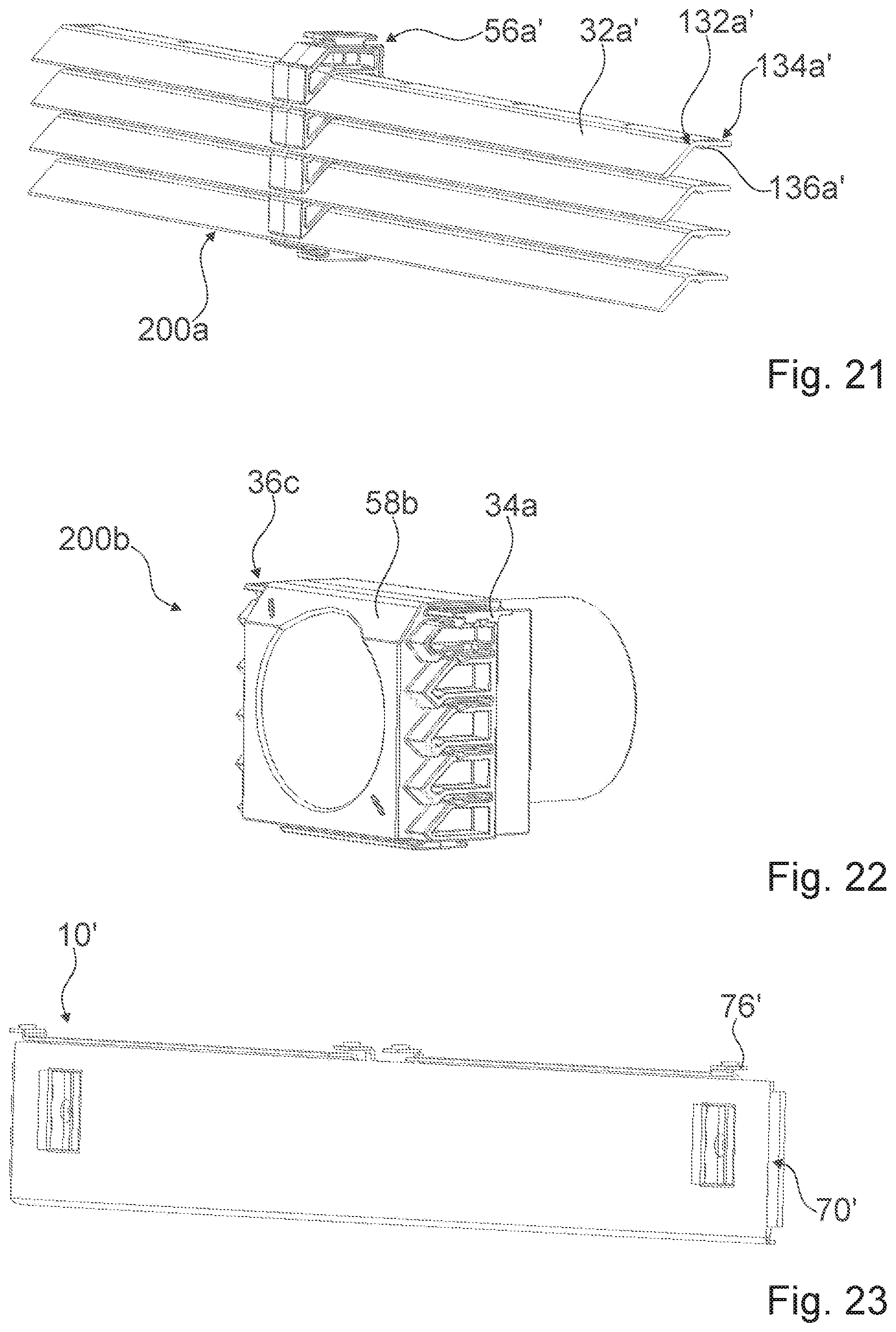
D00013

XML
uspto.report is an independent third-party trademark research tool that is not affiliated, endorsed, or sponsored by the United States Patent and Trademark Office (USPTO) or any other governmental organization. The information provided by uspto.report is based on publicly available data at the time of writing and is intended for informational purposes only.
While we strive to provide accurate and up-to-date information, we do not guarantee the accuracy, completeness, reliability, or suitability of the information displayed on this site. The use of this site is at your own risk. Any reliance you place on such information is therefore strictly at your own risk.
All official trademark data, including owner information, should be verified by visiting the official USPTO website at www.uspto.gov. This site is not intended to replace professional legal advice and should not be used as a substitute for consulting with a legal professional who is knowledgeable about trademark law.