Constructive layout applied to ice tray
Braidotti Cavalari
U.S. patent number 10,697,686 [Application Number 15/795,332] was granted by the patent office on 2020-06-30 for constructive layout applied to ice tray. The grantee listed for this patent is Nely Cristina Braidotti Cavalari. Invention is credited to Nely Cristina Braidotti Cavalari.


| United States Patent | 10,697,686 |
| Braidotti Cavalari | June 30, 2020 |
Constructive layout applied to ice tray
Abstract
An ice tray is provided, which includes a tray used to obtain pieces of ice with spherical geometry. The ice tray includes a base and a cover, provided with a first and a second semi-spherical cavity, respectively, which connect to form a spherical cavity, appropriately suitable for obtaining spherical geometric pieces of ice.
| Inventors: | Braidotti Cavalari; Nely Cristina (Bauru, BR) | ||||||||||
|---|---|---|---|---|---|---|---|---|---|---|---|
| Applicant: |
|
||||||||||
| Family ID: | 63046426 | ||||||||||
| Appl. No.: | 15/795,332 | ||||||||||
| Filed: | October 27, 2017 |
Prior Publication Data
| Document Identifier | Publication Date | |
|---|---|---|
| US 20190041114 A1 | Feb 7, 2019 | |
Foreign Application Priority Data
| Aug 2, 2017 [BR] | 20 2017 016643 | |||
| Current U.S. Class: | 1/1 |
| Current CPC Class: | F25C 1/243 (20130101); F25C 2400/06 (20130101); F25C 1/04 (20130101) |
| Current International Class: | F25C 1/243 (20180101); F25C 1/04 (20180101) |
References Cited [Referenced By]
U.S. Patent Documents
| 225621 | March 1880 | Ligowsky |
| 931497 | August 1909 | Schille |
| 1034580 | August 1912 | Buckau |
| 1348134 | July 1920 | Barnstead |
| 1698332 | January 1929 | Henning |
| 1970128 | August 1934 | Collins |
| 2152467 | March 1939 | Crosby |
| 2247018 | June 1941 | Henning |
| 2317067 | April 1943 | Knaust |
| 2812551 | November 1957 | Chupa |
| D185302 | May 1959 | Mitzenmacher |
| 2946207 | July 1960 | Hulterstrum |
| D188992 | October 1960 | Morrison |
| 2955044 | October 1960 | Tupper |
| 2961850 | November 1960 | Tupper |
| 2980039 | April 1961 | Jolly |
| 3020730 | February 1962 | Harris, Sr. |
| 3070275 | December 1962 | Bostrom |
| 3091194 | May 1963 | Dickinson |
| 3113667 | December 1963 | Knapp |
| 3161031 | December 1964 | Flannery |
| 3197058 | July 1965 | Hale |
| 3287807 | November 1966 | Menke |
| 3306512 | February 1967 | Pagnini |
| 3349941 | October 1967 | Wanderer |
| 3394861 | July 1968 | Truax |
| 3411463 | November 1968 | Moseres |
| 3640081 | February 1972 | Hadden |
| 3685785 | August 1972 | Brown |
| 3736767 | June 1973 | Lukes |
| 3752433 | August 1973 | Berman |
| 3780536 | December 1973 | Fishman |
| 4076207 | February 1978 | Austin |
| 4081122 | March 1978 | Hobson |
| 4091953 | May 1978 | Daenen |
| 4147324 | April 1979 | Walter |
| 4157805 | June 1979 | Haber |
| 4226355 | October 1980 | Helfrich, Jr. |
| 4233819 | November 1980 | Stottmann |
| 4239175 | December 1980 | Straubinger |
| 4268002 | May 1981 | Deveaux |
| 4320849 | March 1982 | Yellin |
| 4360119 | November 1982 | Olivo |
| 4372526 | February 1983 | Daenen |
| 4550575 | November 1985 | DeGaynor |
| 4627595 | December 1986 | Rhodes |
| 4638645 | January 1987 | Simila |
| D290539 | June 1987 | Jennette |
| 4762232 | August 1988 | Sedutto |
| 4872586 | October 1989 | Landis |
| 4886239 | December 1989 | Stimmel |
| 4978022 | December 1990 | Weick |
| 4979370 | December 1990 | Hotaling |
| 5184745 | February 1993 | Havens |
| 5250315 | October 1993 | Loew |
| 5344021 | September 1994 | Rose |
| 5344023 | September 1994 | Cox |
| 5354191 | October 1994 | Bobis |
| 5398908 | March 1995 | Kienle |
| 5409126 | April 1995 | DeMars |
| 5409128 | April 1995 | Mitchell |
| 5433314 | July 1995 | Lin |
| 5474184 | December 1995 | Mandler |
| D365724 | January 1996 | Yu |
| D369506 | May 1996 | Tinius |
| D369507 | May 1996 | Tinius |
| 5520010 | May 1996 | Altman |
| D375964 | November 1996 | Poubouridis |
| 5597500 | January 1997 | Hasenfratz |
| D384960 | October 1997 | Kistler |
| 5775483 | July 1998 | Lown |
| 5787839 | August 1998 | Magnant |
| 5851415 | December 1998 | Thomas |
| 5858263 | January 1999 | Geary |
| 6176464 | January 2001 | Harvey |
| RE37213 | June 2001 | Staggs |
| 6269964 | August 2001 | Turner, Jr. |
| 6301919 | October 2001 | Blaustein |
| D457782 | May 2002 | Snell |
| D480604 | October 2003 | Lillelund |
| D484745 | January 2004 | Watson |
| D504286 | April 2005 | de Cleir |
| 6886694 | May 2005 | McNeeley |
| 7128230 | October 2006 | Jacobson |
| D535348 | January 2007 | Sammann |
| 7252280 | August 2007 | Hollands |
| 7510096 | March 2009 | Wang |
| 7523915 | April 2009 | Halpin |
| D623898 | September 2010 | Snell |
| 7832586 | November 2010 | Vovan |
| 7963500 | June 2011 | Holiday |
| D661540 | June 2012 | Facey |
| D677968 | March 2013 | Bond |
| D684019 | June 2013 | Facey |
| 8474641 | July 2013 | Hays |
| D687681 | August 2013 | Barber |
| D689746 | September 2013 | Zorovich |
| D689747 | September 2013 | Zorovich |
| D693189 | November 2013 | Facey |
| D693625 | November 2013 | Facey |
| 8770431 | July 2014 | Glaser |
| D731264 | June 2015 | Frank |
| 9771191 | September 2017 | Loaiza Alvarez |
| 9869503 | January 2018 | Saeks |
| 10245522 | April 2019 | Williams |
| 2005/0064069 | March 2005 | Adams |
| 2005/0202138 | September 2005 | Kazich |
| 2007/0107447 | May 2007 | Langlotz |
| 2007/0262230 | November 2007 | McDermott, Jr. |
| 2009/0088273 | April 2009 | Nardacci |
| 2009/0158755 | June 2009 | Cutting |
| 2012/0237656 | September 2012 | Henry |
| 2013/0011530 | January 2013 | Wolf |
| 2014/0137576 | May 2014 | Culley |
| 2014/0165610 | June 2014 | Boarman |
| 2014/0165618 | June 2014 | Culley |
| 2014/0165619 | June 2014 | Culley |
| 2015/0021458 | January 2015 | Zorovich |
| 2015/0107275 | April 2015 | Papalia |
| 2016/0216020 | July 2016 | Safrin |
| 2016/0341461 | November 2016 | Williams |
| 2018/0304167 | October 2018 | Jones |
| 102015025211 | Apr 2017 | BR | |||
| 204027112 | Dec 2014 | CN | |||
Attorney, Agent or Firm: Schmeiser, Olsen & Watts, LLP
Claims
The invention claimed is:
1. A stackable ice tray, suitable for forming pieces of ice with a spherical geometry, comprising: a substantially cylindrical base having an upper region, lower region, and central region, wherein a first semispherical cavity is located in the central portion, and wherein the lower portion has two semicircular recesses on diametrically opposite sides of the base; a cover having a second semispherical cavity and a surrounding ring positioned externally to the second semispherical cavity, wherein the surrounding ring of the cover has two diametrically opposed tabs projecting from the cover; wherein the first and second semispherical cavity connect to form a single spherical cavity capable of holding water when the cover is placed onto the base.
2. The stackable ice tray of claim 1, wherein the two diametrically opposed tabs projecting from the cover may engage two semicircular recesses of a lower portion of a second stackable ice tray of the same design.
3. The stackable ice tray of claim 2, wherein engagement between the two diametrically opposed tabs from the cover and the two semicircular recesses of the lower portion of the second stackable ice tray creates a gap suitable for the circulation of convective currents between the stackable ice tray and the second stackable ice tray.
4. The stackable ice tray of claim 2, wherein the upper portion of the base has a rim comprising a step and the step acts as a support for front and rear sides of a lower portion of a base of the second stackable ice tray, wherein the front and rear sides are the sides not including the two semicircular recesses.
5. The stackable ice tray of claim 1, wherein the central portion of the base has a smaller circumference than the upper portion and the lower portion.
6. The stackable ice tray of claim 1, wherein the two diametrically opposed tabs projecting from the cover have a saddle-shaped curvature.
7. The stackable ice tray of claim 1, wherein the cover has a hole surrounded by a circular elevation.
8. The stackable ice tray of claim 1, wherein the cover is at least substantially inside the base when the cover is placed onto the base and the spherical cavity is formed.
9. The stackable ice tray of claim 8, wherein the two diametrically opposed tabs projecting from the cover extend out of the base.
10. The stackable ice tray of claim 1, wherein pressure applied to the two diametrically opposed tabs projecting from the cover releases the cover from the base.
Description
CROSS-REFERENCE TO RELATED APPLICATIONS
This application claims priority to Brazilian Application No. 20 2017 016643-6, having a filing date of Aug. 2, 2017, the entire contents of which are hereby incorporated by reference.
FIELD OF TECHNOLOGY
This following deals with an object contained in the field of household utensils, particularly utensils used to obtain pieces of ice.
It is a device with the function of obtaining pieces of ice with spherical geometry and appropriate for stacking, which attribute to the product a unique and distinctive character before its congeners.
BACKGROUND
As is widely known in the consumer market in general, Brazil has a great demand for ice trays, due to the predominance of high temperatures during most of the year. In these warmer periods, the consumer is looking for alternatives to appease the effects of heat, especially by using ice to conserve drinks at low temperatures.
In recent years, the market has come to require coverable trays for producing pieces of ice in a variety of shapes, in contrast to conventional cubes or chips. However, the State of the Art still lacks practical, efficient and inexpensive solutions to obtain spherical geometric pieces of ice, especially in domestic environments.
The utility model patent document CN204027112 discloses a silica gel form to obtain spherical pieces of ice. However, the bulged shape of the base of the tray/mold precludes its stacking, so that embodiments of the reference do not optimize the space used. Still, the reference features tabs in formats that do not guarantee practical handling by the user. Finally, the said document does not carry out the detailed description of all its elements, so that reproduction of embodiments of the reference by a person skilled in the art is compromised.
The utility model patent document BR102015025211-0 relates to a substantially square ice tray for obtaining spherical pieces of ice. Having substantially different constructivity in relation to embodiments of the present invention, this priority does not solve the adversity of stacking the trays, since the tray does not have the necessary means for safe and efficient stacking.
Thus, it is envisaged that the prior art and the consumer market would benefit from the introduction of a form for obtaining spherical geometric ice, of simple manufacture and practical handling, suitable to be stacked safely and efficiently.
SUMMARY
An aspect relates to an ice tray, which has a constructive arrangement where a base and a cover, both fit with semi-spherical cavities, are connected for the formation of a spherical cavity, appropriately suitable for obtaining pieces of ice with spherical geometry.
The said ice tray also has, in the region of the cover, two diametrically opposite flaps, which both facilitate the withdrawal of the piece of ice from the present utility model and also serve as support for safe and efficient stacking of the trays.
BRIEF DESCRIPTION
Some of the embodiments will be described in detail, with reference to the following figures, wherein like designations denote like members, wherein:
FIG. 1 shows a perspective view of an ice tray according to an embodiment;
FIG. 2 shows a top view of the ice tray;
FIG. 3 shows a lower view of the ice tray;
FIG. 4 shows a front view of the ice tray;
FIG. 5 shows a side view of the ice tray;
FIG. 6 shows a front cross-sectional view of the ice tray;
FIG. 7 shows a cutaway perspective view of the ice tray;
FIG. 8 shows a perspective view of a base of an ice tray according to an embodiment;
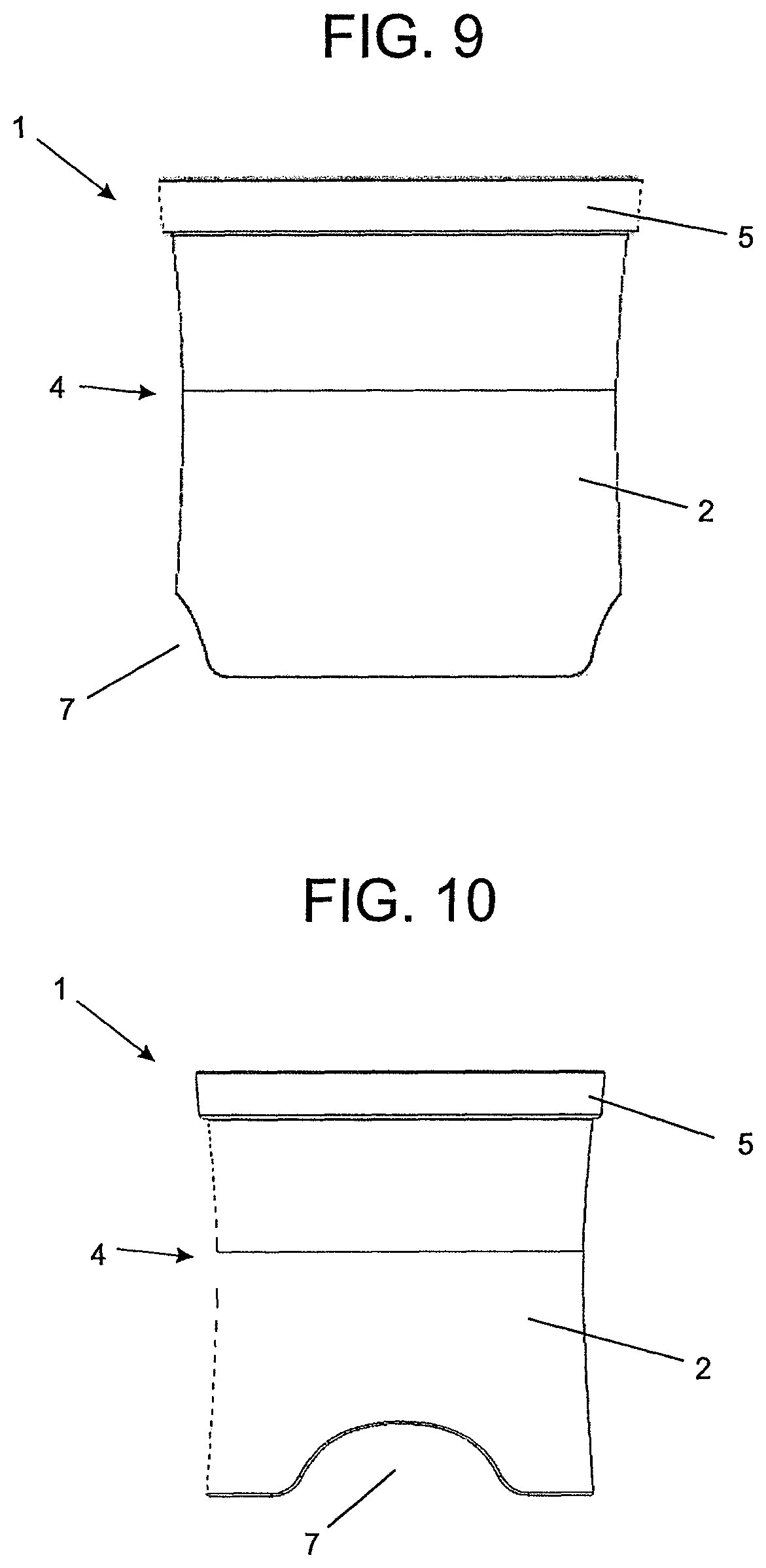
FIG. 9 shows a front view of the base;
FIG. 10 shows side view of the base;
FIG. 11 shows a perspective view of a cover of an ice tray according to an embodiment;
FIG. 12 shows front view of the cover;
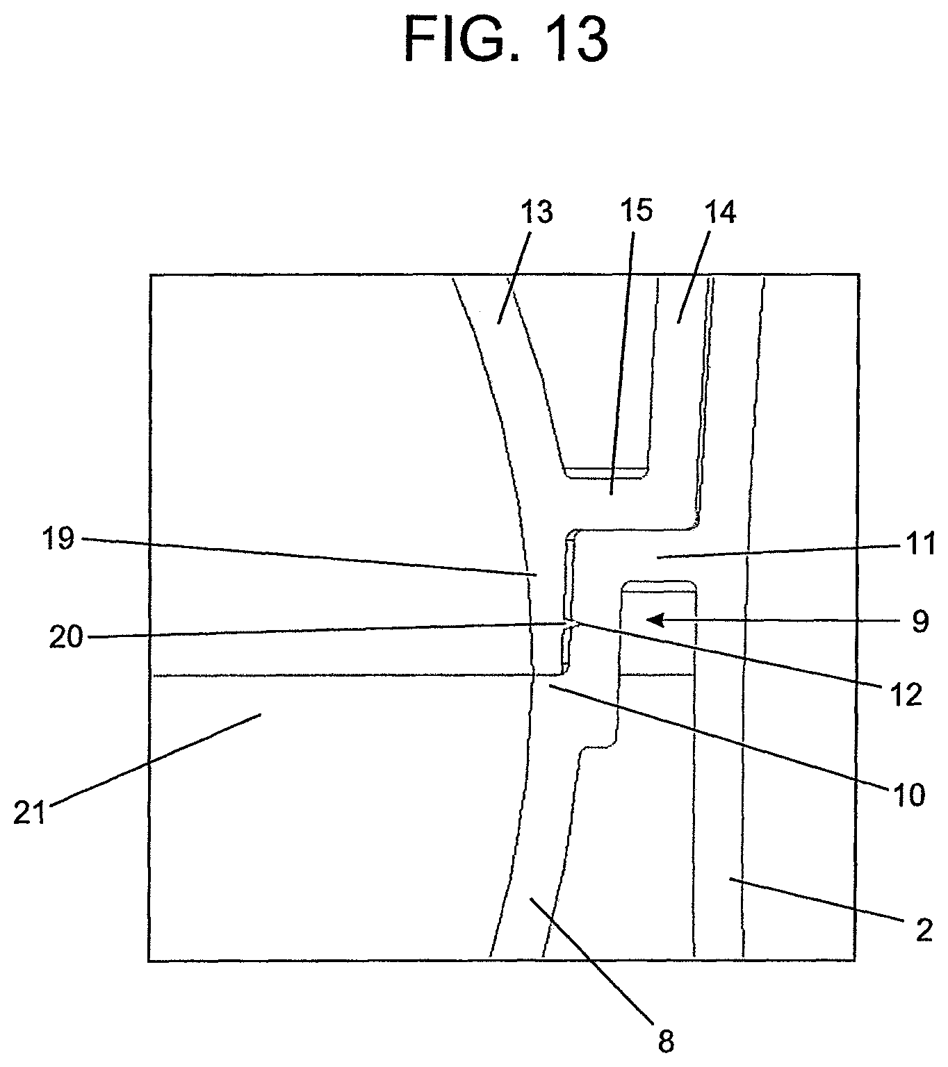
FIG. 13 shows a cross-sectional view of a connection between a base and a cover of an ice tray according to an embodiment;
FIG. 14 shows a perspective view of stacked ice trays according to an embodiment; and
FIG. 15 shows a front view of the stacked ice trays.
DETAILED DESCRIPTION
According to the above figures, embodiments of this invention "CONSTRUCTION LAYOUT APPLIED TO ICE TRAY", may include an ice tray (1), made of plastic material, which comprises two main parts, being:
(a) a base (2) of substantially cylindrical shape with a central region (4) smoothly bulged and of smaller diameter in relation to lower and upper regions of the base (2); the upper portion of the base 2 is provided with a larger diameter rim 5, which defines a step 6; the lower portion of the base (2) is provided with two semicircular recesses (7) on the sides and diametrically opposite; inside, the base (2) has a first semispherical cavity (8), connected to the walls of the base (2) by means of an intermediate region (9), which defines a first flat region (10), a second flat region (11) and at least one surrounding groove (12); (b) a cover (3) with a central region provided with a second semispherical cavity (13); the cover is provided with a surrounding ring (14) positioned externally to the second semispherical cavity (13); a third flat region (15) is defined between the second semispherical cavity (13) and the surrounding ring (14) of the cover (3); the surrounding ring (14) of the cover (3) has two diametrically opposed tabs (16) with a saddle-shaped curvature projected toward the outer region parallel to the semicircular recesses (7) of the base (2); in the upper portion of the second semispherical cavity (13), the cover (3) has a hole (17) surrounded by a circular elevation (18); in its lower portion, the cover (3) has a lower ring (19) provided with at least one surrounding elevated rim (20).
The engagement between the base (2) and the cover (3) occurs by means of a connection between the surrounding elevated rim (20) of the cover (3) and the surrounding groove (12) of the base (2), as shown in detail in FIG. 13. Besides, it is noted that the third flat region (15) rests against the second flat region (11) and the lower end of the lower ring (19) rests against the first flat region (10), ensuring a perfect fit between the elements of the tray (1) and the correct geometry of the piece of ice obtained from the present utility model. The connection between the base (2) and the cover (3) results in a connection between the first (8) and the second (13) semispherical cavities, which give rise to a spherical cavity (21), the purpose of which is to form pieces of ice with spherical geometry.
The hole (17) of the cover (3), surrounded by a circular elevation (18), has two functions. On the one hand, the hole (17) acts as a means for the inflow of liquids, which fill the spherical cavity (21) formed by the coupling of the first (8) and the second (13) semispherical cavities, originated by means of the connection between the cover (3) and the base (2). On the other hand, the hole (17) is responsible for directing and outputting any excess liquid deposited in the spherical cavity (21).
The withdrawal of the spherical geometric piece of ice is carried out by simultaneously pressing the flaps (16) radially towards the center of the tray (1), so as to disengage the surrounding projection (20) and the surrounding groove (12). Thereafter, the cover (3) is removed and finally the piece of ice is removed from the tray (1). Advantageously, the saddle-shaped flaps (16) of the cover (3) conform to the user's fingers, while the slightly bulged shape of the central region (4) of the base (2) allows it to conform to the user's hand, facilitating the removal of the piece of ice from this utility model.
Another aspect of the present ice tray (1) is that it is suitable for stacking, optimizing the space occupied in its transport, storage and use. The flaps (16) of the cover (3) and the semicircular recesses (7) of the base (2) correspond to each other and are connected when two or more ice trays (1) are stacked. However, the connection between the flaps (16) and the semicircular recesses (7) has been designed to create a gap (22), suitable for the circulation of convective currents between the ice trays (1). The gaps (22) assist and promote the solidification of the liquid stored inside the spherical cavities (21) of the trays (1) and the consequent formation of spherical geometric pieces of ice. Further, the step (6) acts as a support for the front and rear portions of the stacked trays (1), complementing the support of the side portions provided by the flaps (16).
Although the present invention has been disclosed in the form of preferred embodiments and variations thereon, it will be understood that numerous additional modifications and variations could be made thereto without departing from the scope of the invention.
For the sake of clarity, it is to be understood that the use of `a` or `an` throughout this application does not exclude a plurality, and `comprising` does not exclude other steps or elements.
* * * * *
D00000
D00001
D00002
D00003
D00004
D00005
D00006
D00007
D00008
D00009
XML
uspto.report is an independent third-party trademark research tool that is not affiliated, endorsed, or sponsored by the United States Patent and Trademark Office (USPTO) or any other governmental organization. The information provided by uspto.report is based on publicly available data at the time of writing and is intended for informational purposes only.
While we strive to provide accurate and up-to-date information, we do not guarantee the accuracy, completeness, reliability, or suitability of the information displayed on this site. The use of this site is at your own risk. Any reliance you place on such information is therefore strictly at your own risk.
All official trademark data, including owner information, should be verified by visiting the official USPTO website at www.uspto.gov. This site is not intended to replace professional legal advice and should not be used as a substitute for consulting with a legal professional who is knowledgeable about trademark law.