Air circulator with vein control system
Ediger , et al.
U.S. patent number 10,697,656 [Application Number 15/543,669] was granted by the patent office on 2020-06-30 for air circulator with vein control system. This patent grant is currently assigned to Vornado Air, LLC. The grantee listed for this patent is Vornado Air, LLC. Invention is credited to Brian M. Cartwright, Glen W. Ediger, Timothy Holub, Gary Israel, Gregory Pease.
View All Diagrams
| United States Patent | 10,697,656 |
| Ediger , et al. | June 30, 2020 |
Air circulator with vein control system
Abstract
The present invention is related in general to air circulators, and in particular, to an air circulator with a vein control system to direct and adjust airflow patterns. According to an exemplary embodiment, the present invention provides adjustable, vertical veins that are attached to the outlet of a tower fan. According to a preferred embodiment, the veins are pivotally mounted in such a way that by turning a knob, the veins can either be directed into a focused air-flow pattern or adjusted to a divergent air-flow pattern, or at any setting in between.
| Inventors: | Ediger; Glen W. (North Newton, KS), Israel; Gary (Andover, KS), Cartwright; Brian M. (Wichita, KS), Pease; Gregory (Andover, KS), Holub; Timothy (Cheney, KS) | ||||||||||
|---|---|---|---|---|---|---|---|---|---|---|---|
| Applicant: |
|
||||||||||
| Assignee: | Vornado Air, LLC (Andover,
KS) |
||||||||||
| Family ID: | 56849025 | ||||||||||
| Appl. No.: | 15/543,669 | ||||||||||
| Filed: | March 3, 2016 | ||||||||||
| PCT Filed: | March 03, 2016 | ||||||||||
| PCT No.: | PCT/US2016/020790 | ||||||||||
| 371(c)(1),(2),(4) Date: | July 14, 2017 | ||||||||||
| PCT Pub. No.: | WO2016/141252 | ||||||||||
| PCT Pub. Date: | September 09, 2016 |
Prior Publication Data
| Document Identifier | Publication Date | |
|---|---|---|
| US 20180003401 A1 | Jan 4, 2018 | |
Related U.S. Patent Documents
| Application Number | Filing Date | Patent Number | Issue Date | ||
|---|---|---|---|---|---|
| 62128890 | Mar 5, 2015 | ||||
| Current U.S. Class: | 1/1 |
| Current CPC Class: | F04D 29/444 (20130101); F04D 25/10 (20130101); F24F 7/007 (20130101); F24F 1/0025 (20130101); F24F 13/1413 (20130101); F04D 17/04 (20130101); F24F 1/0287 (20190201); F05B 2260/506 (20130101); F05B 2250/314 (20130101); F05B 2250/324 (20130101); F05B 2250/315 (20130101); F05B 2250/323 (20130101) |
| Current International Class: | F24F 7/007 (20060101); F24F 13/14 (20060101); F24F 1/0025 (20190101); F24F 1/0287 (20190101); F04D 29/44 (20060101); F04D 17/04 (20060101); F04D 25/10 (20060101) |
References Cited [Referenced By]
U.S. Patent Documents
| 2224312 | December 1940 | O'Day |
| 5063833 | November 1991 | Hara |
| 5080002 | January 1992 | Soethout |
| 5092518 | March 1992 | Tomioka |
| 5324164 | June 1994 | Doering |
| 5470276 | November 1995 | Burnell |
| 5520579 | May 1996 | Saida |
| 5690550 | November 1997 | Mikowski |
| 6120372 | September 2000 | Riello |
| 6800023 | October 2004 | Demerath |
| 7827810 | November 2010 | Hur |
| 9758020 | September 2017 | Oe |
| 9878596 | January 2018 | Ross |
| 2011/0294413 | December 2011 | Perella |
| 2018/0304725 | October 2018 | Araujo Nieto |
| 1727764 | Feb 2006 | CN | |||
| 102713125 | Oct 2012 | CN | |||
| 102004004427 | Sep 2005 | DE | |||
| 102005037748 | Feb 2007 | DE | |||
| 1867507 | Dec 2007 | EP | |||
| 2002293133 | Oct 2002 | JP | |||
| 2008209043 | Sep 2008 | JP | |||
| 2013167414 | Aug 2013 | JP | |||
| WO-2014020952 | Feb 2014 | WO | |||
Other References
|
Chinese search report for corresponding CN 2016800123352 dated Apr. 26, 2019 (Year: 2019). cited by examiner . Chinese First Office Action for corresponding CN 2016800123352 dated May 7, 2019 (Year: 2019). cited by examiner. |
Primary Examiner: Edgar; Richard A
Assistant Examiner: Elliott; Topaz L.
Parent Case Text
RELATED APPLICATIONS
The present application claims priority to PCT Application. No. PCT/US2016/020790 filed Mar. 3, 2016, which claims priority to U.S. Provisional Application No. 62/128,890 filed Mar. 5, 2015.
Claims
What is claimed is:
1. An air circulation system, wherein the air circulation system comprises: a blower; wherein the blower is vertically aligned; wherein the blower directs a laminar flow of air in a direction which is perpendicular to the vertical alignment of the blower; a mounting platform, wherein the mounting platform is secured above the blower; wherein a first major axis of the mounting platform is aligned substantially parallel to the laminar flow of the air from the blower; a front post and a rear post secured to the mounting platform; wherein the front post and the and rear post are arranged along a line which is parallel to the laminar flow of the air from the blower; a vertically aligned cam system; wherein the cam system comprises a cam knob, a cam stem and a cam lobe; wherein the cam lobe is rotatably secured to the mounting platform; further wherein the cam knob is secured to the cam lobe by the vertically aligned cam stem; an air outlet portion, wherein the air outlet portion is comprised of a plurality of vanes; wherein the vanes are vertically aligned; wherein each of the vanes is comprised of a plurality of upstream ribs and at least one downstream rib; wherein the upstream ribs and the at least one downstream rib are joined at a center axis; wherein the upstream ribs are aligned in a first direction; wherein the at least one downstream rib is aligned in a second direction which is offset from the first direction; wherein each of the plurality of vanes further comprises at least one pivot pin; a slide mechanism, wherein the slide mechanism comprises: an upper slot, wherein the upper slot encloses and is mechanically engaged with the cam lobe; a body; a front slide slot, wherein the front slide slot encloses and slidably engages with the front post; a rear slide slot, wherein the rear slide slot encloses and slidably engages with the rear post; and a plurality of angled slots; wherein each of the angled slots is formed within the body of the slide mechanism; wherein the plurality of angled slots comprise at least a first angled slot and a second angled slot; wherein the first angled slot has a first major axis aligned in a first direction; wherein the second angled slot has a second major axis aligned in a second direction; wherein the first direction and the second directions are different directions so that lines along the first and second major axes of the first and second angled slots intersect at exactly one point; wherein each of the pivot pins of the plurality of vanes is slidably engaged within one of the plurality of angled slots; wherein each of the pivot pins is configured to slide within one of the plurality of angled slots when the slide mechanism is horizontally translated along the upper platform in response to a horizontal translation of the cam lobe within the upper slot of the slide mechanism.
2. The air circulation system of claim 1, wherein the at least one pivot pin of each vane is attached to at least one of the plurality of upstream ribs.
3. The air circulation system of claim 1, wherein each of the angled slots has a major axis aligned in a different direction so that the lines along the major axes of any two of the angled slots intersect at exactly one point.
4. The air circulation system of claim 1, wherein the cam lobe comprises an eccentric circular shape.
5. The air circulation system of claim 1, wherein the vanes are formed of injection molded plastic.
6. The air circulation system of claim 1, wherein the cam system is configured to translate the rotational movement of the knob between a first forward position and a second rear position.
7. The air circulation system of claim 6, wherein in the first forward position, the vanes are positioned to direct the air flow from the blower in a plurality of divergent directions.
8. The air circulation system of claim 7, wherein in the second rear position, the vanes are positioned to direct the air flow from the blower in a plurality of convergent directions.
9. The air circulation system of claim 1, wherein the vanes comprise one or more curved surfaces.
10. The air circulation system of claim 1, wherein the slide mechanism is located above the plurality of vanes.
11. The air circulation system of claim 1, wherein the slide mechanism is located beneath the plurality of vanes.
Description
FIELD OF INVENTION
The present invention is related in general to air circulators, and in particular, to an air circulator with a vein control system to direct and adjust airflow patterns.
BACKGROUND OF THE INVENTION
The cross-flow tower fan air moving device is well known in the art. Typically, in a vertically oriented cross-flow blower, air is drawn through the blower from one side and directed out through air exits on an adjacent side. Due to the aerodynamic principles that are well known in the art, the exit air is fairly laminar as it exists in a vertically oriented pattern from the fan housing. The laminar flows created by conventional tower fan designs are very effective at directing a steady flow of air in a given direction. However, conventional fan designs do not allow for manipulating the airflow to create a variety of desired air flow patterns.
Based on the foregoing, the present invention provides an improved fan design which can direct channeled air to create a variety of air flow patterns. The present invention overcomes the short coming of the prior art by accomplishing this critical objective.
SUMMARY OF THE DISCLOSURE
To minimize the limitations found in the prior art, and to minimize other limitations that will be apparent upon the reading of the specifications, the preferred embodiment of the present invention provides adjustable, vertical veins that are attached to the outlet of a tower fan. According to a preferred embodiment, the veins of the present invention are pivotally mounted in such a way that by turning a knob, the veins can either be directed into a focused air-flow pattern or adjusted to a divergent air-flow pattern, or at any setting in between.
These and other advantages and features of the present invention are described with specificity so as to make the present invention understandable to one of ordinary skill in the art.
BRIEF DESCRIPTION OF THE DRAWINGS
Elements in the figures have not necessarily been drawn to scale in order to enhance their clarity and improve understanding of these various elements and embodiments of the invention. Furthermore, elements that are known to be common and well understood to those in the industry are not depicted in order to provide a clear view of the various embodiments of the invention, thus the drawings are generalized in form in the interest of clarity and conciseness.
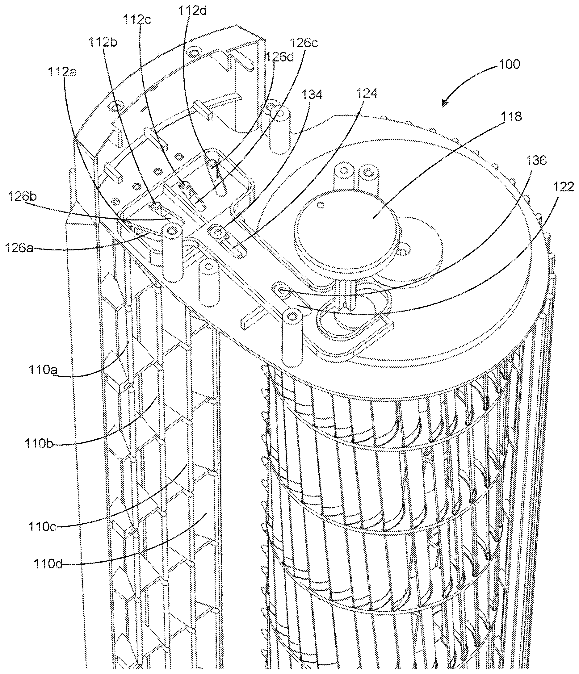
FIG. 1 shows a perspective view of the interior of a fan assembly in accordance with a first preferred embodiment of the present invention in which the veins are in a divergent configuration and the slider mechanism is in a forward position.
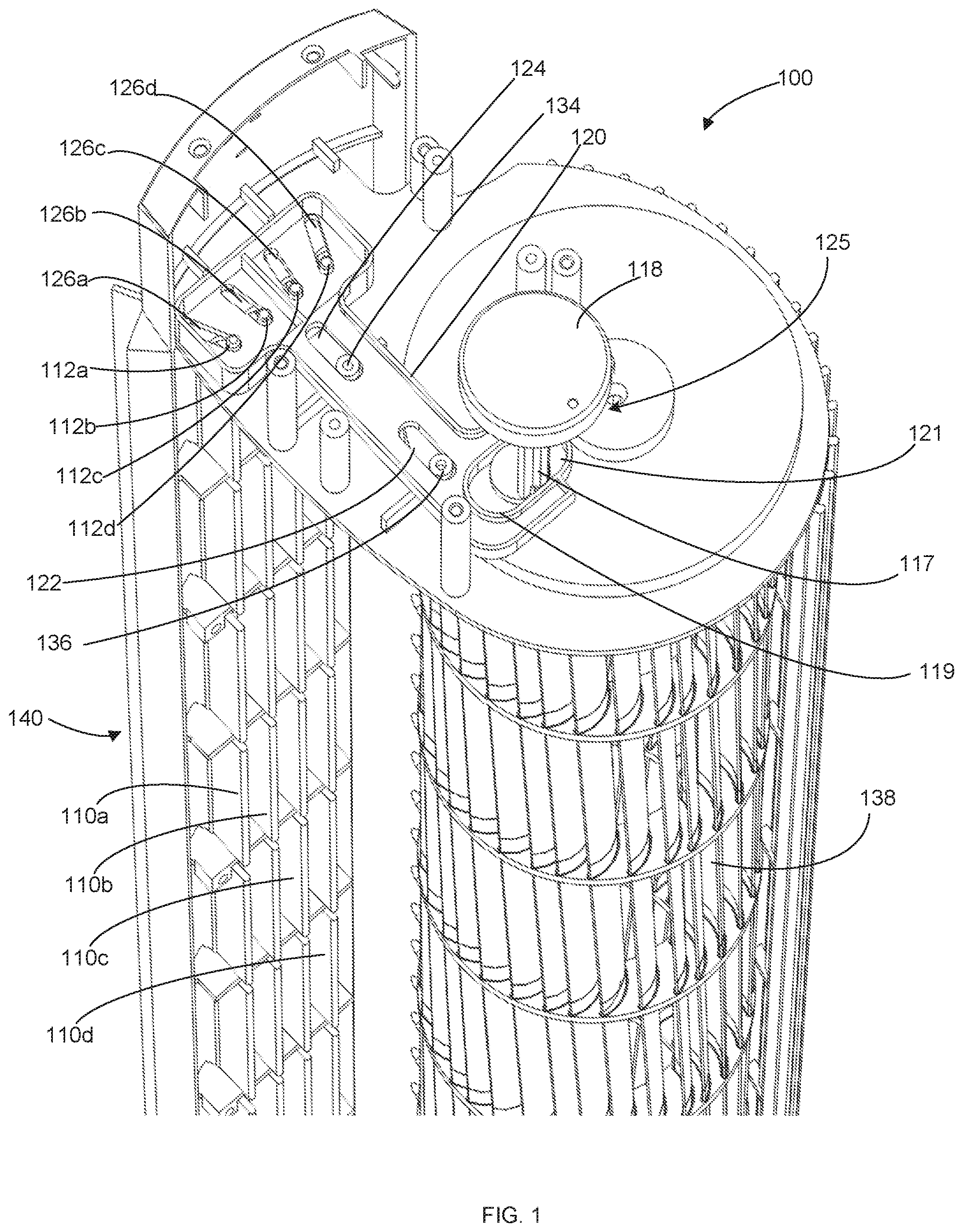
FIG. 2 shows a perspective view of the interior of a fan assembly in accordance with a first preferred embodiment of the present invention in which veins are in a divergent configuration and the slider mechanism is in a forward position.
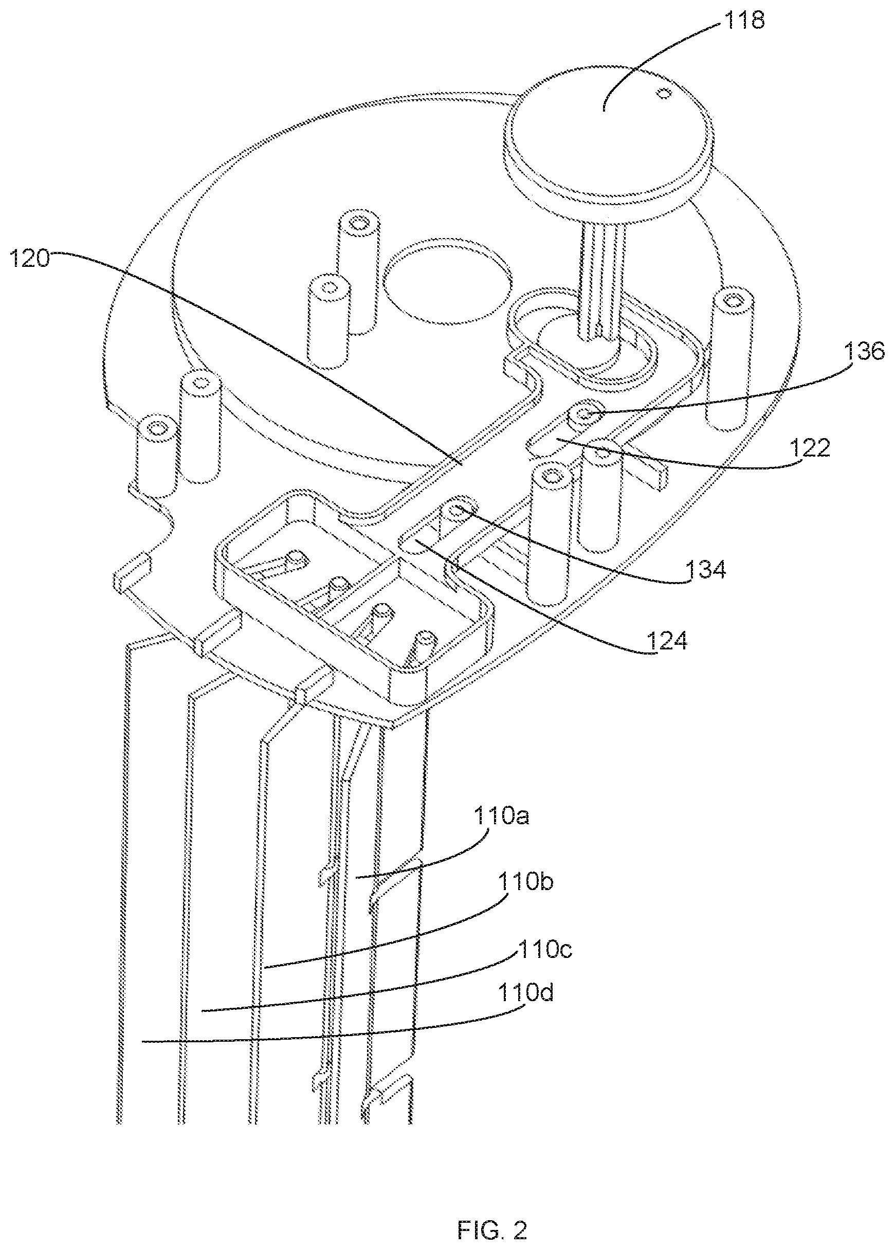
FIG. 3 shows a perspective view of a fan assembly in accordance with a first preferred embodiment of the present invention in which the knob is in a forward, disperse position and the veins are in a divergent configuration.
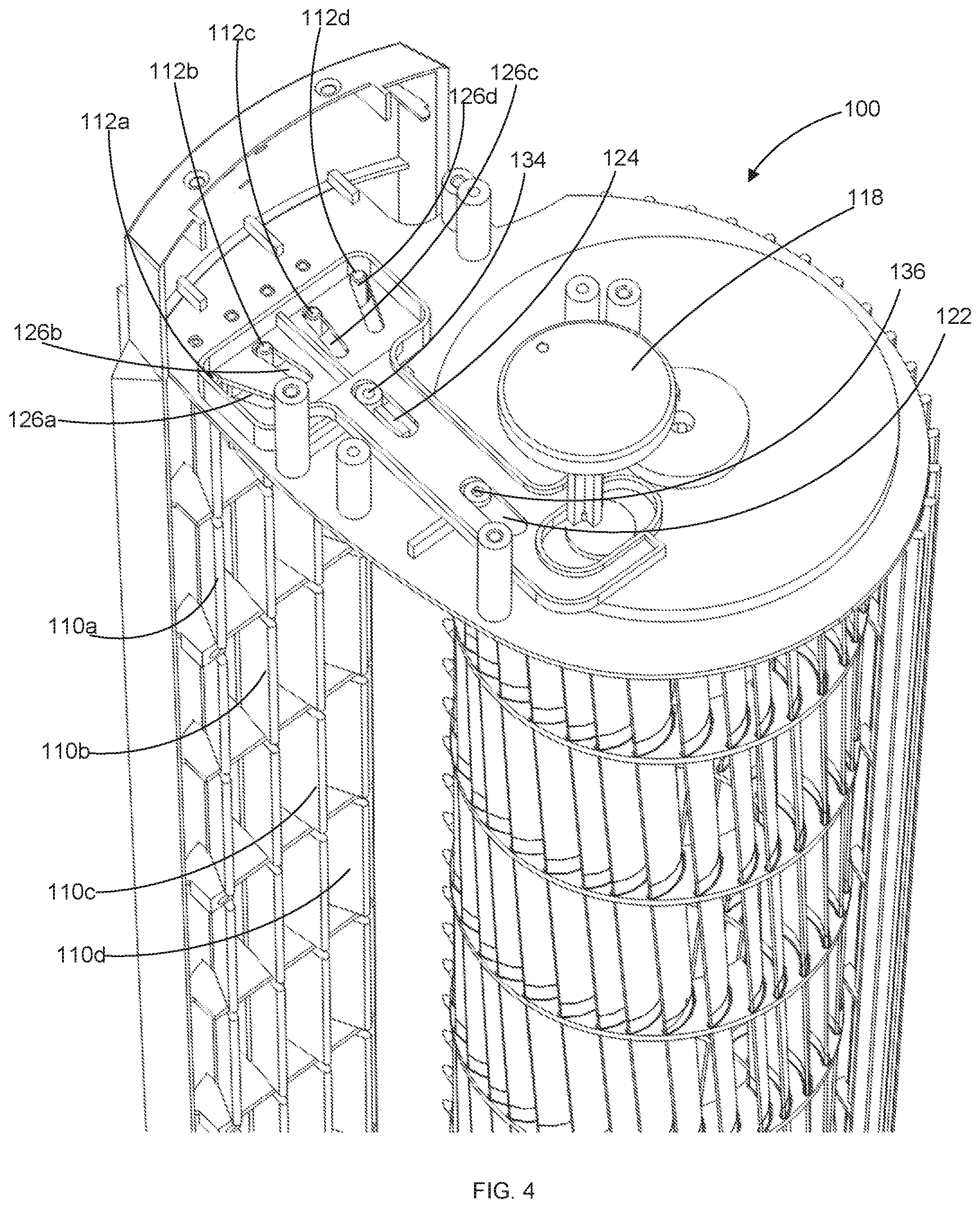
FIG. 4 shows a perspective view of a fan assembly in accordance with a first preferred embodiment of the present invention in which the veins are in a focused configuration and the slider mechanism is in the back position.
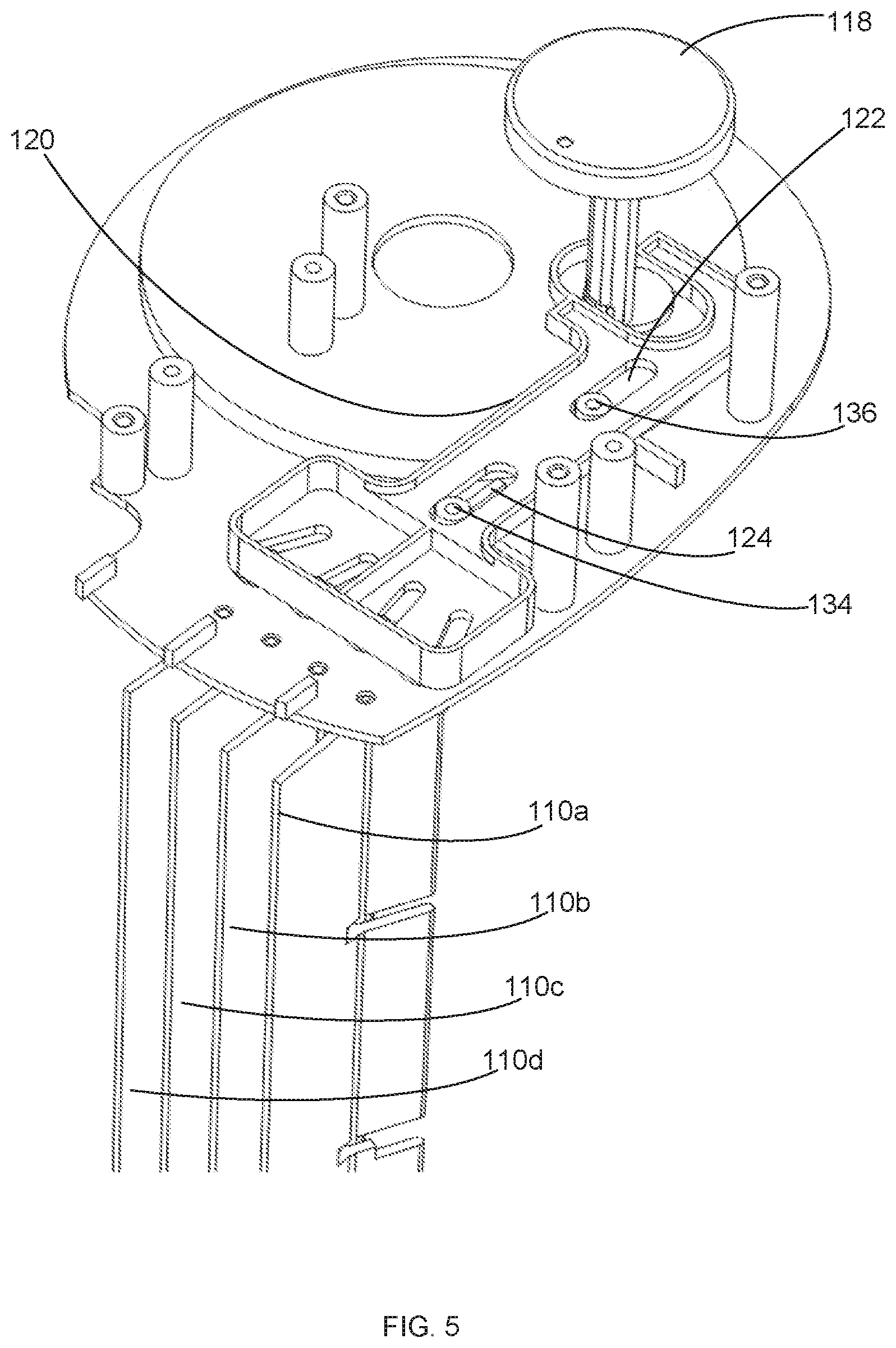
FIG. 5 shows a perspective view of a fan assembly in accordance with a first preferred embodiment of the present invention in which the veins are in a focused configuration and the slider mechanism is in the back position.
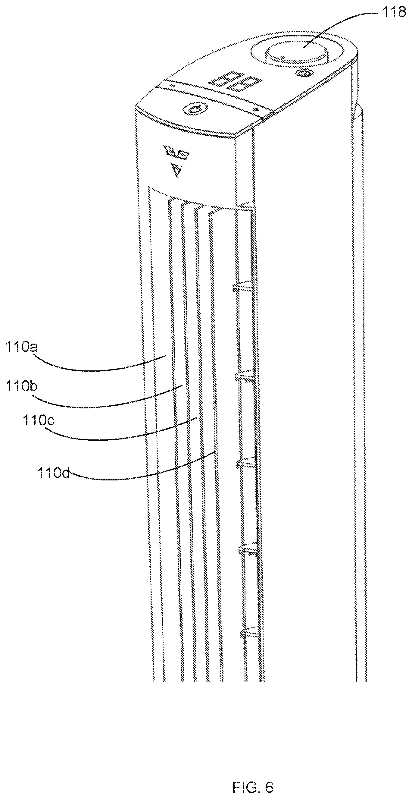
FIG. 6 shows a perspective view of a fan assembly in accordance with a first preferred embodiment of the present invention in which the veins are in a focused position.
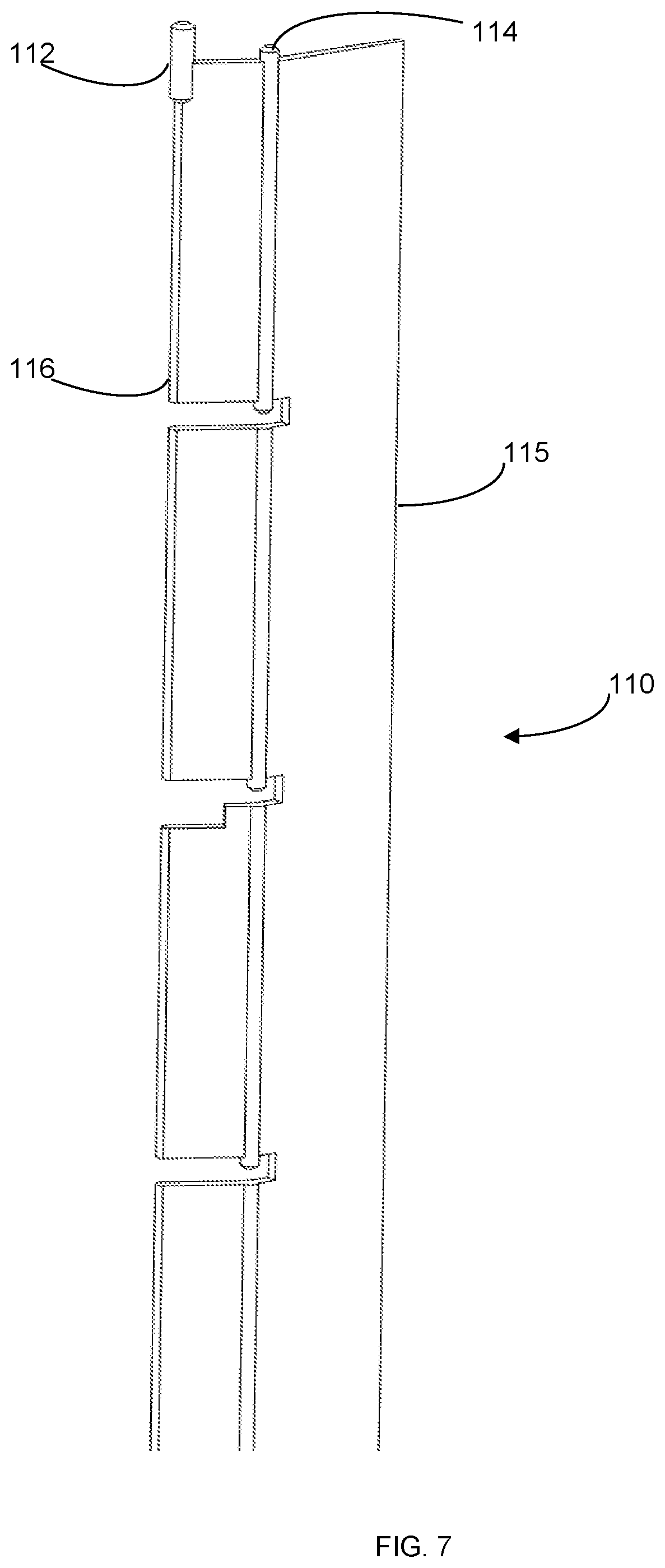
FIG. 7 shows a perspective view of a single vein assembly with a pivot pin in accordance with a first preferred embodiment of the present invention.
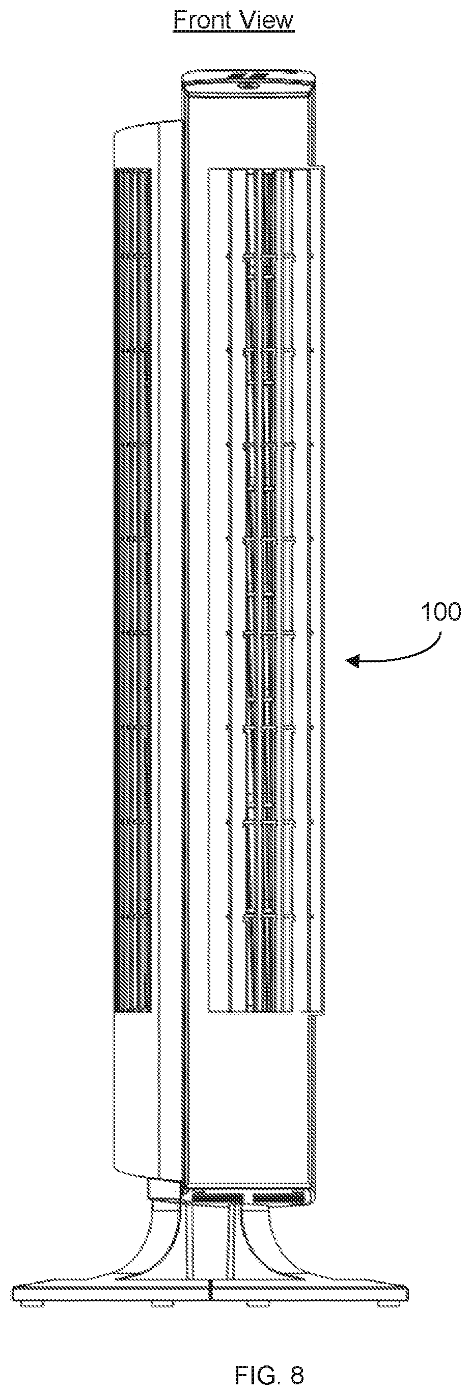
FIG. 8 shows a front view of a fan tower of the present invention in accordance with a first preferred embodiment of the present invention.
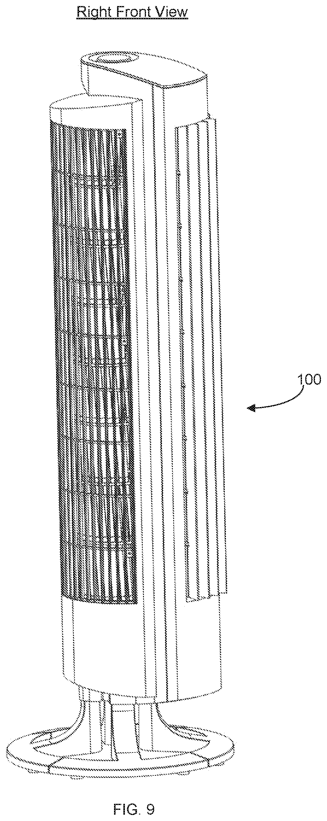
FIG. 9 shows a right front view of a fan tower in accordance with a first preferred embodiment of the present invention.
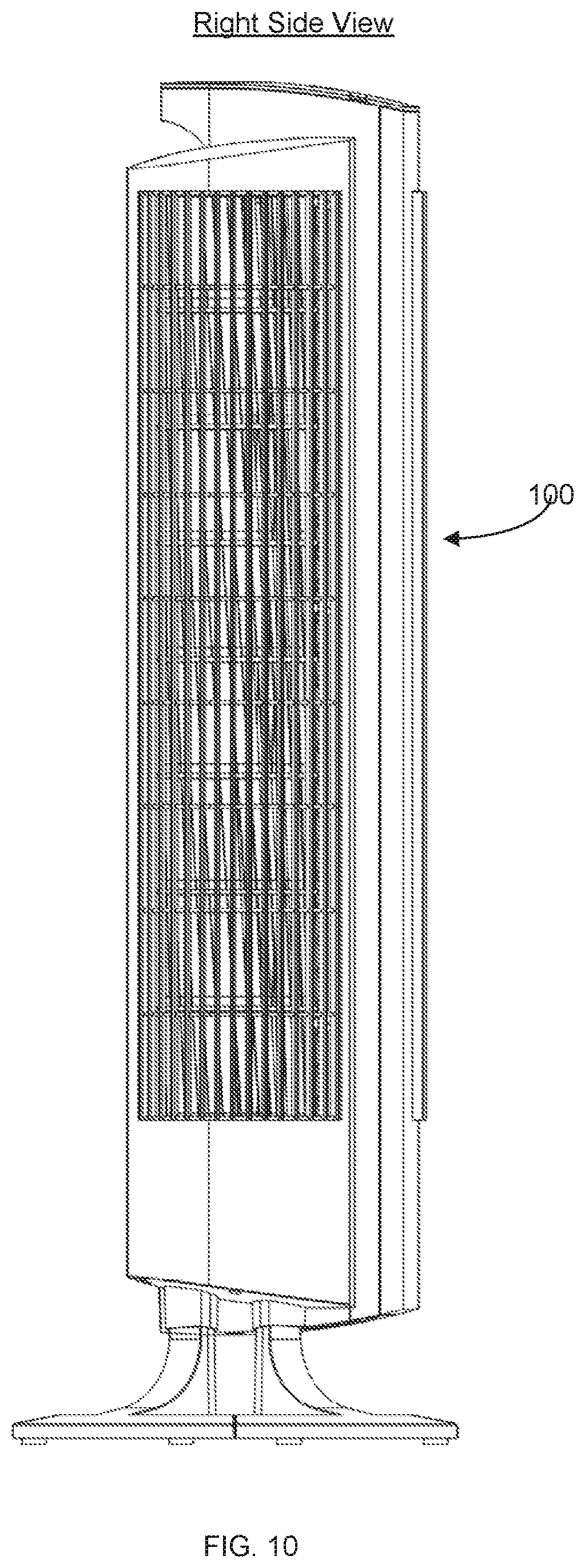
FIG. 10 shows a right side view of a fan tower in accordance with a first preferred embodiment of the present invention.
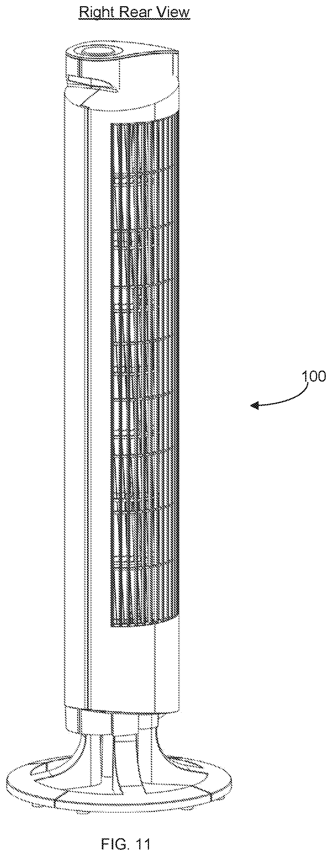
FIG. 11 shows a right rear view of a fan tower in accordance with a first preferred embodiment of the present invention.
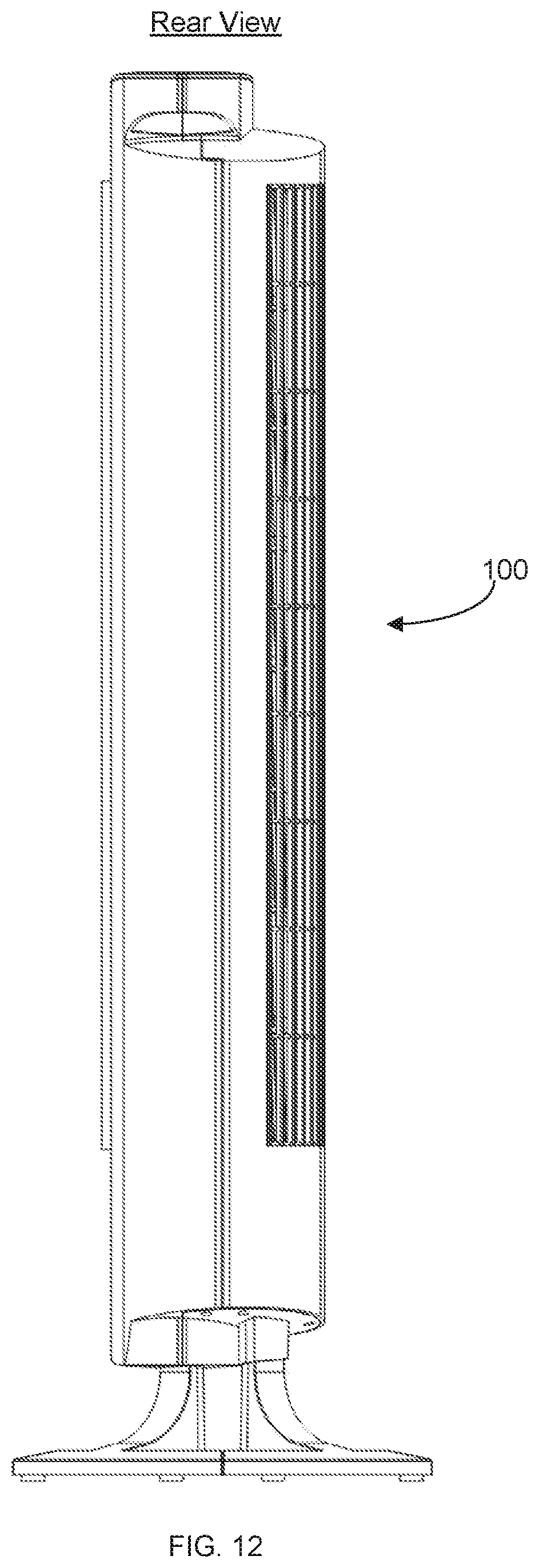
FIG. 12 shows a rear view of a fan tower in accordance with a first preferred embodiment of the present invention.
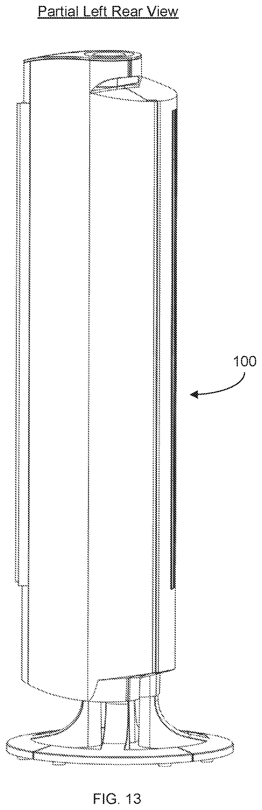
FIG. 13 shows a partial left rear view of a fan tower in accordance with a first preferred embodiment of the present invention.
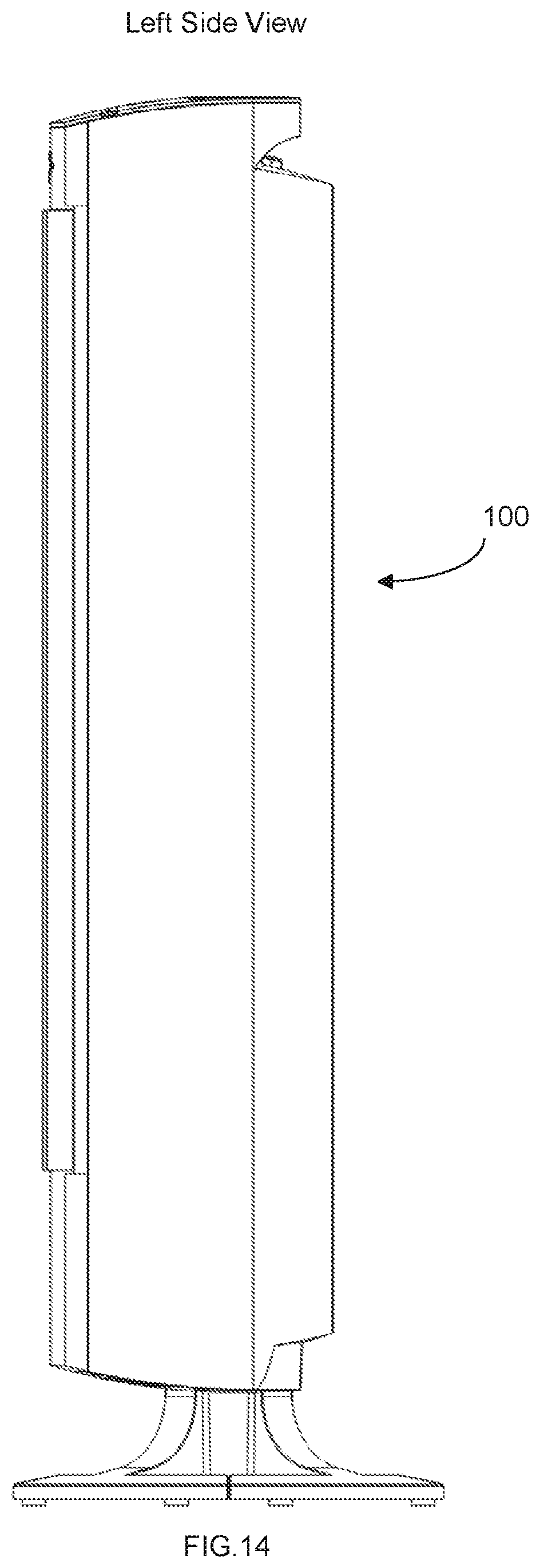
FIG. 14 shows a left side view of a fan tower in accordance with a first preferred embodiment of the present invention.
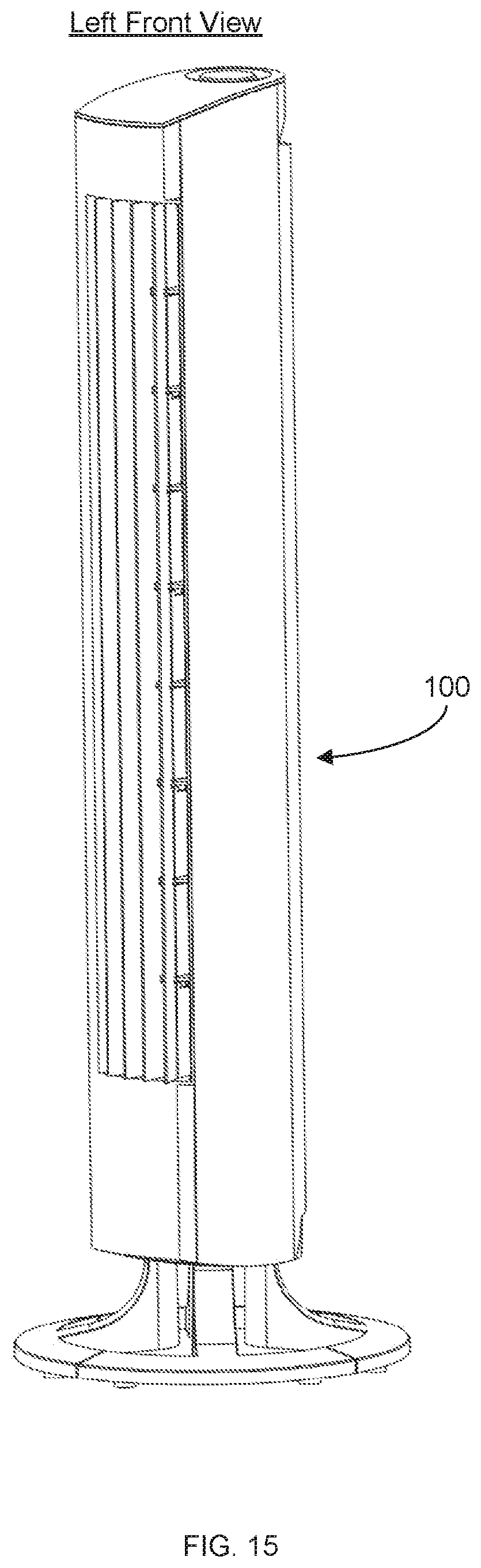
FIG. 15 shows a left front view of a fan tower in accordance with a first preferred embodiment of the present invention.
FIG. 16 shows a bottom view of a fan tower in accordance with a first preferred embodiment of the present invention.
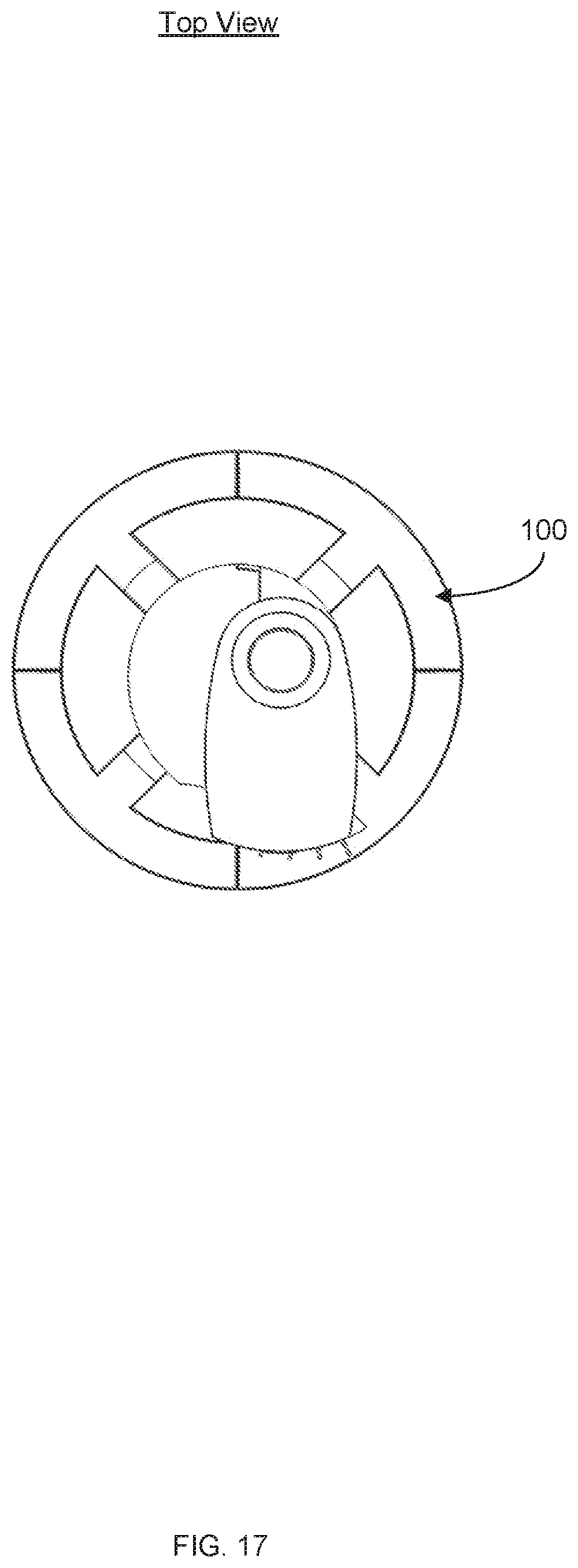
FIG. 17 shows a top view of a fan tower in accordance with a first preferred embodiment of the present invention.
DETAILED DESCRIPTION OF THE DRAWINGS
In the following discussion that addresses a number of embodiments and applications of the present invention, reference is made to the accompanying drawings that form a part hereof, and in which is shown by way of illustration specific embodiments in which the invention may be practiced. It is to be understood that other embodiments may be utilized and changes may be made without departing from the scope of the present invention.
Various inventive features are described below that can each be used independently of one another or in combination with other features. However, any single inventive feature may not address any of the problems discussed above or only address one of the problems discussed above. Further, one or more of the problems discussed above may not be fully addressed by any of the features described below.
FIG. 1 illustrates a perspective view of the interior of an air tower circulator 100 in accordance with a first preferred embodiment of the present invention. As shown, the exemplary air tower circulator 100 includes a vertical air blower 138 which directs a flow of air into an air outlet portion 140. As shown, the air outlet portion 140 includes a set of adjustable, pivotally mounted veins 110a, 110b, 110c, 110d which each include respective pivot pins 112a, 112b, 112c and 112d. As further shown in FIG. 1, veins 110a-110d are operatively connected to a sliding mechanism 120 by having pivot pins 112a-112d respectively engaged into angled slots 126a, 126b, 126c and 126d.
As further shown in FIG. 1, the sliding mechanism 120 is preferably guided by a front post 134 secured into a front slide slot 124; and a rear post 136 secured into a rear slide slot 122. Preferably, the front post 134 and rear post 136 are affixed to a secure, stationary part of the larger fan body. Additionally, sliding mechanism 120 preferably further includes a large slot 119 running perpendicular to the slide slots 122, 124 to provide engagement with a cam mechanism 125, in operation, the cam mechanism 125 preferably rotates about an axis that is attached to an eccentric circular shaped cam lobe 121. Preferably, rotating the cam lobe 121 about the axis provides a front to back motion of the sliding mechanism 120 along the two slide slots 122, 124.
According to a further preferred embodiment, the cam lobe 121 may be circular in shape and preferably fitted to contain the sliding mechanism 120 from moving either forward or backwards, and to keep the veins 110a-110d in the desired position. As further shown, the cam lobe 121 is preferably activated by a knob 118 which is attached to the cam lob 121 via cam stem 117 which aligned with the pivot axis of the cam lobe 121. Accordingly, rotating the knob 118 in either direction will preferably cause the sliding mechanism 120 to move forward or back and thereby move the veins 110a-110d from a divergent position as shown in FIGS. 1-3) to a convergent position (as shown in FIGS. 4-6) or any stopping point desired in-between. Alternatively, the sliding mechanism 121 may be adjusted directly without the use of the cam mechanism 125.
With reference now to FIG. 7, an exemplary vein 110 for use with the present invention is further illustrated (the terms "vein" and "vane" are used interchangeably herein). As shown, the exemplary vein 110 preferably includes upstream, vertical ribs 116 and a downstream portion 115. According to a preferred embodiment, the vertical ribs 116 preferably include an additional pivot pin 112 designed to fit into an angled slot (i.e. one of slots 126a-126d shown in FIG. 1). As discussed below, vein 110 further includes an axis 114 about which the veins can be pivoted to direct air flow. According to a further aspect of the present invention, vein 110 may be made of an injection molded plastic and may be molded-in, in the form of multiple pivot points. According to the present invention, the pivot points 114 of the vein are preferably secured into top and bottom members (not shown) and may further include multiple sub-divided supports in-between.
According to alternative embodiments, the veins may be designed in various cross-sectional configurations, including aerodynamic air-foil shapes, rectangular shapes, or bent shapes, such as a dogleg bend (as illustrated in the preferred embodiment) or gentle curves. Advantageously, when the veins are configured in a dog-leg (bent) cross section design and moved to the focused position, the upstream dog-leg bend also has the effect of nearly closing off the outer slots, and thus directs more air to the center openings resulting in an even higher air velocity, which is desirable in the focused configuration.
With reference again to FIG. 1, according to a preferred embodiment, the knob 118 preferably acts as an adjustable control to simultaneously angle the veins 110a-110d in order to focus the channels of air, or to simultaneously angle the veins to defuse the air channels. In operation, the angle, spacing, and length of the angled slots 126a-126d, in coordination with the travel length of the sliding mechanism 120, determine the amount, the direction, and the angle of the veins. In the examples shown in FIGS. 1, 2 and 3, the knob 118 is shown in a disbursement position. As shown, in this position, the sliding mechanism 120 has been pushed forward causing the pivot pins 112a-112d to travel upwards within their respective angled slots 126a-126d, thereby moving the veins 110a-110d to a divergent configuration which disburses the channels of air. Conversely, in the examples shown in FIGS. 4, 5 and 6, the knob 118 is shown turned to a focusing position. In this position, the sliding mechanism 120 has been pushed forward to cause the veins 110a-110d to narrow to a focusing configuration, which focuses the channels of air.
In accordance with alternative preferred embodiments, there may be any number of veins used, from one to several. Further, although four vertically oriented veins are shown in the preferred configuration, other vein orientations may include horizontal or angled veins or a combination of orientations. Additionally, multiple ribs may be used with each rib having a unique shape for aerodynamic reasons. Still further, although the linkage between the veins and the sliding mechanism 120 is shown in the preferred configuration as being accomplished and controlled from the top end of the vein assembly, this linkage and control can be arranged from the bottom of the veins or from any location in-between.
The foregoing description of the preferred embodiment of the present invention has been presented for the purpose of illustration and description. It is not intended to be exhaustive or to limit the invention to the precise form disclosed. Many modifications and variations are possible in light of the above teachings. It is intended that the scope of the present invention not be limited by this detailed description, but by the claims and the equivalents to the claims appended hereto. The above described embodiments, while including the preferred embodiment and the best mode of the invention known to the inventor at the time of filing, are given as illustrative examples only. It will be readily appreciated that many deviations may be made from the specific embodiments disclosed in this specification without departing from the spirit and scope of the invention. Accordingly, the scope of the invention is to be determined by the claims below rather than being limited to the specifically described embodiments above.
* * * * *
D00000
D00001
D00002
D00003
D00004
D00005
D00006
D00007
D00008
D00009
D00010
D00011
D00012
D00013
D00014
D00015
D00016

D00017
XML
uspto.report is an independent third-party trademark research tool that is not affiliated, endorsed, or sponsored by the United States Patent and Trademark Office (USPTO) or any other governmental organization. The information provided by uspto.report is based on publicly available data at the time of writing and is intended for informational purposes only.
While we strive to provide accurate and up-to-date information, we do not guarantee the accuracy, completeness, reliability, or suitability of the information displayed on this site. The use of this site is at your own risk. Any reliance you place on such information is therefore strictly at your own risk.
All official trademark data, including owner information, should be verified by visiting the official USPTO website at www.uspto.gov. This site is not intended to replace professional legal advice and should not be used as a substitute for consulting with a legal professional who is knowledgeable about trademark law.