Valve train device
Stolk , et al.
U.S. patent number 10,697,330 [Application Number 15/773,078] was granted by the patent office on 2020-06-30 for valve train device. This patent grant is currently assigned to Daimler AG. The grantee listed for this patent is Daimler AG. Invention is credited to Thomas Stolk, Alexander Von Gaisberg-Helfenberg.
| United States Patent | 10,697,330 |
| Stolk , et al. | June 30, 2020 |
Valve train device
Abstract
A valve train device, in particular for an internal combustion engine, includes a support element and a cam element which can be moved axially relative to the support element. The valve train device further includes a switch unit for axially moving the cam element, which switch unit includes a displacer that is intended to be at least operatively inserted between the support element and the cam element in order to axially move the cam element.
| Inventors: | Stolk; Thomas (Kirchheim, DE), Von Gaisberg-Helfenberg; Alexander (Beilstein, DE) | ||||||||||
|---|---|---|---|---|---|---|---|---|---|---|---|
| Applicant: |
|
||||||||||
| Assignee: | Daimler AG (Stuttgart,
DE) |
||||||||||
| Family ID: | 56936381 | ||||||||||
| Appl. No.: | 15/773,078 | ||||||||||
| Filed: | September 15, 2016 | ||||||||||
| PCT Filed: | September 15, 2016 | ||||||||||
| PCT No.: | PCT/EP2016/001549 | ||||||||||
| 371(c)(1),(2),(4) Date: | May 02, 2018 | ||||||||||
| PCT Pub. No.: | WO2017/076482 | ||||||||||
| PCT Pub. Date: | May 11, 2017 |
Prior Publication Data
| Document Identifier | Publication Date | |
|---|---|---|
| US 20180320561 A1 | Nov 8, 2018 | |
Foreign Application Priority Data
| Nov 3, 2015 [DE] | 10 2015 014 175 | |||
| Current U.S. Class: | 1/1 |
| Current CPC Class: | F01L 1/267 (20130101); F01L 13/0036 (20130101); F01L 1/047 (20130101); F01L 1/053 (20130101); F01L 2013/10 (20130101); F01L 2013/0052 (20130101) |
| Current International Class: | F01L 1/047 (20060101); F01L 13/00 (20060101); F01L 1/053 (20060101); F01L 1/26 (20060101) |
| Field of Search: | ;123/90.16,90.18,90.27,90.17 |
References Cited [Referenced By]
U.S. Patent Documents
| 8365692 | February 2013 | Schoeneberg |
| 9038584 | May 2015 | Kashiwabara et al. |
| 2007/0178731 | August 2007 | Elendt |
| 2010/0175652 | July 2010 | Schoeneberg |
| 2014/0102391 | April 2014 | Kappler |
| 2014/0165940 | June 2014 | Woo |
| 2014/0238323 | August 2014 | Kashiwabara |
| 2015/0075467 | March 2015 | Kotani |
| 2015/0075468 | March 2015 | Takagi |
| 2015/0330270 | November 2015 | Noda |
| 2017/0191387 | July 2017 | Takagi |
| 196 11 641 | Jun 1997 | DE | |||
| 10 2014 002 268 | Sep 2014 | DE | |||
| 2013-19307 | Jan 2013 | JP | |||
| 2013-83202 | May 2013 | JP | |||
| 2013083202 | May 2013 | JP | |||
| 2013-139739 | Jul 2013 | JP | |||
Other References
|
PCT/EP2016/001549, International Search Report dated Feb. 3, 2017 (Three (3) pages). cited by applicant. |
Primary Examiner: Kramer; Devon C
Assistant Examiner: Stanek; Kelsey L
Attorney, Agent or Firm: Crowell & Moring LLP
Claims
The invention claimed is:
1. A valve train device, comprising: a support element; a cam element, wherein the cam element is configured to move axially relative to the support element and wherein the cam element has a multitrack cam; and a switch unit for axially moving the cam element, wherein the switch unit includes a first displacer, wherein the switch unit and the first displacer are disposed external to the support element and are disposed axially between the support element and the multitrack cam such that the first displacer slides laterally on the support element and is operatively inserted between the support element and the cam element so as to axially move the cam element in a first direction, wherein the first displacer is configured to move radially relative to the cam element, wherein the first displacer has an inclined surface, and wherein the inclined surface is inserted between the cam element and the support element.
2. The valve train device according to claim 1, wherein the support element is fixed to a housing.
3. The valve train device according to claim 1, wherein the inclined surface comes into contact with the cam element and axially moves the cam element when operatively inserted between the support element and the cam element.
4. The valve train device according to claim 1, wherein the switch unit includes a housing and wherein the first displacer is mounted on the housing.
5. The valve train device according to claim 1, wherein the switch unit has a second displacer that is operatively inserted between the support element and the cam element so as to axially move the cam element in a second direction that is counter to the first direction.
6. The valve train device according to claim 1, wherein the first displacer forms an axial bearing for the cam element.
7. The valve train device according to claim 1, wherein the support element forms a radial bearing for the cam element.
8. An internal combustion engine, comprising: a valve train device including: a support element; a cam element, wherein the cam element is configured to move axially relative to the support element and wherein the cam element has a multitrack cam; and a switch unit for axially moving the cam element, wherein the switch unit includes a displacer, wherein the switch unit and the displacer are disposed external to the support element and are disposed axially between the support element and the multitrack cam such that the displacer slides laterally on the support element and is operatively inserted between the support element and the cam element so as to axially move the cam element, wherein the displacer is configured to move radially relative to the cam element, wherein the displacer has an inclined surface, and wherein the inclined surface is inserted between the cam element and the support element.
Description
BACKGROUND AND SUMMARY OF THE INVENTION
The invention relates to a valve train device.
A valve train device for internal combustion engines, comprising an axially movable cam element on which a shift gate is provided, into which gate a shift element is introduced in order to convert a rotational movement of the cam element into an axial movement of the cam element, is already known from DE 196 11 641 C1.
The object of the invention is in particular to provide a compact valve train device.
A valve train device, in particular for an internal combustion engine, is proposed, comprising a support element and at least one cam element which can be moved axially relative to the support element, which cam element has at least one multitrack cam, the device also comprising a switch unit for axially moving the at least one cam element, which unit comprises at least one displacer that is intended to be at least operatively inserted between the support element and the cam element in order to axially move the at least one cam element. A shift gate can therefore be omitted, and the axial installation space required for the cam element can be reduced. A compact valve train device can thus be provided. "The displacer is intended to be at least operatively inserted between the support element and the cam element in order to axially move the at least one cam element" should be understood in this context to mean that the displacer is incorporated in a functional chain between the support element and the cam element and is supported by the support element such that the cam element is moved axially. In particular, the displacer can be inserted directly between the support element and the cam element and can directly displace the cam element in the axial direction. Alternatively, the displacer can be inserted between the support element and a further element, for example, and can displace the further element, the cam element then being axially moved by the further element.
Moreover, it is proposed that the support element should be fixed to a housing. As a result, the cam element can be particularly well supported while being axially moved.
It is also proposed that the displacer should be radially movable relative to the at least one cam element. This makes it possible to achieve a motion for operatively inserting the displacer between the support element and the cam element which is shorter than a path of movement of the cam element. Therefore, this makes it possible to achieve particularly rapid changeover between two switch positions which are associated with different axial positions of the cam element.
Furthermore, it is proposed that the displacer should have an inclined surface for insertion between the cam element and the support element. A displacement movement can thus be initiated substantially smoothly and a load on the valve train device can be reduced. In principle, the displacer can also have a straight surface, and the cam element, or a component connected to the cam element, can have the inclined surface.
It is additionally proposed that the inclined surface should be provided for coming into contact with the cam element and axially moving the cam element when operatively inserted between the support element and the cam element. A displacement movement can thus be initiated substantially smoothly and a load on the valve train device can be reduced.
It is also proposed that the switch unit should comprise a housing on which the displacer is substantially mounted. A particularly compact valve train device can thus be achieved. "The displacer is substantially mounted on the housing" should be understood in this context to mean that when the displacer is not operatively inserted between the support element and the cam element, at least 60 percent, advantageously at least 80 percent, and particularly preferably the entirety of the displacer is accommodated in the housing.
It is further proposed that the switch unit should have a further displacer that is intended to be inserted at least operatively between the support element and the cam element in order to axially move the cam element in a direction counter to the axial movement caused by the displacer. This thus makes it possible to achieve rapid changeover between two switch positions which are associated with different axial positions of the cam element. In principle, the displacer and the further displacer can be coupled by a rocker to avoid both displacers being operatively inserted at the same time. Alternatively, the displacers can also be uncoupled.
It is also proposed that the displacer should form an axial bearing for the cam element. An additional axial bearing for the camshaft can thereby be omitted, and a compact valve train device can be achieved. The displacer can form the axial bearing for the cam element entirely, or can form the axial bearing together with further components.
Moreover, it is proposed that the support element should form a radial bearing for the cam element. An additional radial bearing for the camshaft can thereby be omitted, and a compact valve train device can be achieved. The support element can form the radial bearing for the cam element entirely, or form the radial bearing together with further components.
The invention also relates to an internal combustion engine comprising a valve train device having at least one support element and at least one cam element which can be moved axially relative to the support element, which cam element has at least one multitrack cam, the device also having a switch unit for axially moving the at least one cam element, which unit comprises at least one displacer that is intended to be at least operatively inserted between the support element and the cam element in order to axially move the at least one cam element.
Further advantages are indicated in the following description of the drawings. The drawings show an embodiment of the invention. The drawings, the description of the drawings and the claims contain many features in combination. A person skilled in the art will advantageously also consider the features individually and combine them to form meaningful further combinations.
BRIEF DESCRIPTION OF THE DRAWINGS
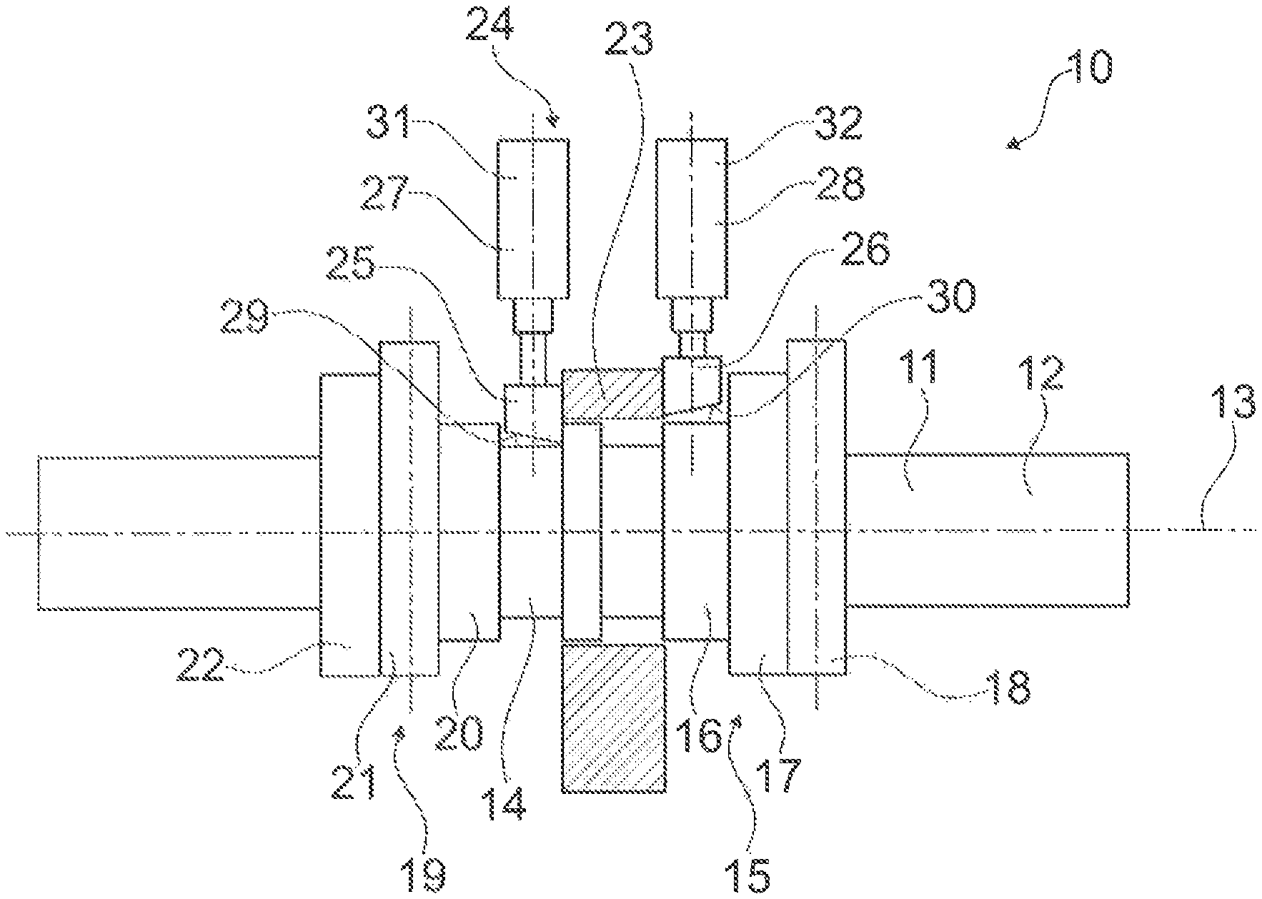
FIG. 1 shows a valve train device in a first switch state, which device is for an internal combustion engine and comprises a support element and a cam element which can be moved axially relative to the support element, the device also comprising a switch unit for axially moving the cam element, which unit comprises at least one displacer that is intended to be inserted between the cam element and the support element in order to axially move the at least one cam element, and
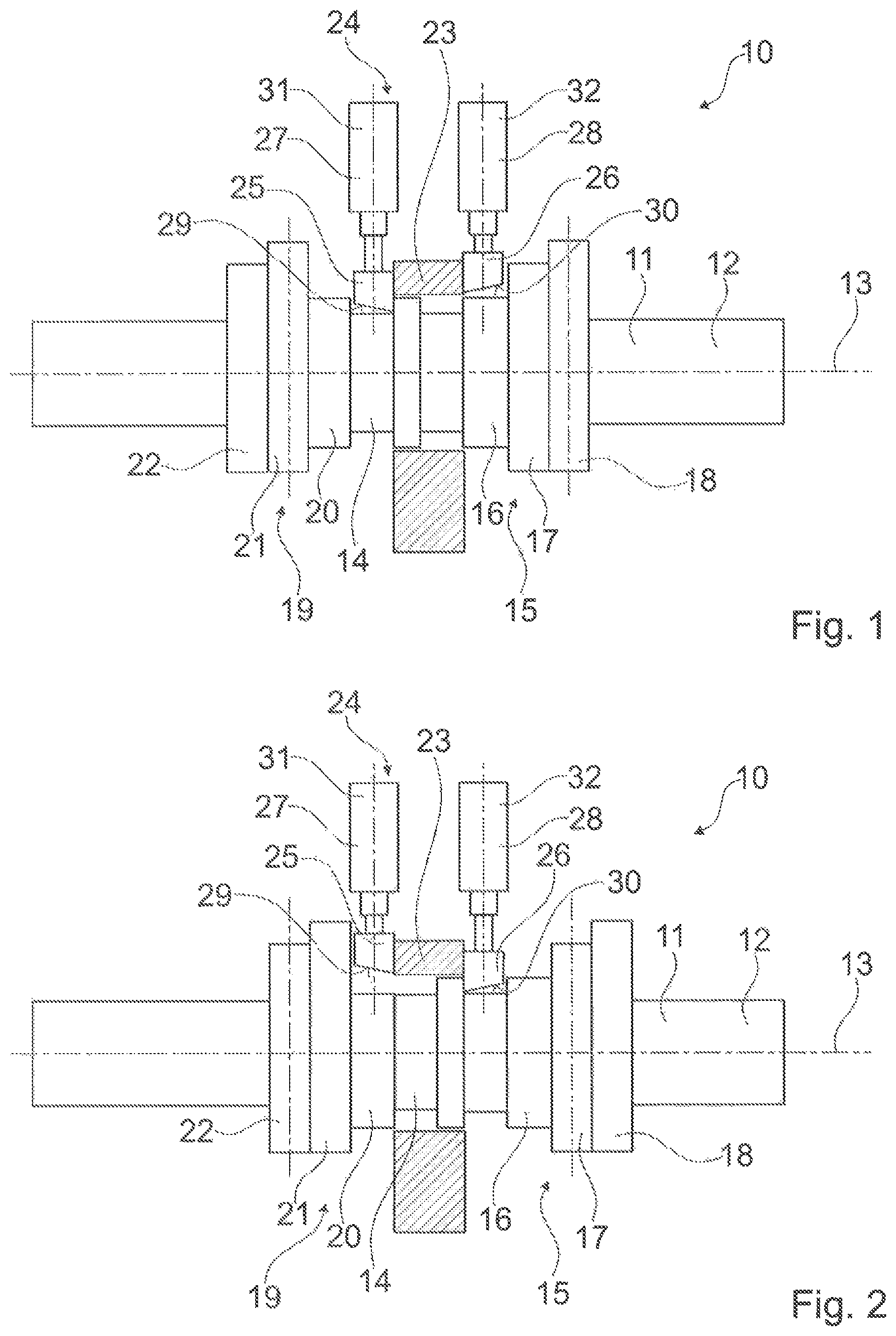
FIG. 2 shows the valve train device in a second switch state.
DETAILED DESCRIPTION OF THE DRAWINGS
FIGS. 1 and 2 show a valve train device 10 for an internal combustion engine, comprising an axially movable cam element 14 which has two multitrack cams 15, 19, each of which has two cam tracks 17, 18, 21, 22. The valve train device 10 is provided for actuating gas exchange valves (not shown in greater detail) of the internal combustion engine (not shown in greater detail) by means of the cam tracks 17, 18, 21, 22. The cam tracks 17, 18, 21, 22 provide different valve lifts and/or valve timings for the gas exchange valves. The cam element has two peripheral surfaces 20, 16.
The valve train device 10 comprises a camshaft 11, which has a drive shaft 12 and the cam element 14. The cam element 14 is rotationally fixed to the drive shaft 12, but can be moved in both axial directions. The drive shaft 12 has spur teeth on the outer periphery thereof. The cam element 14 has corresponding spur teeth on the inner periphery thereof, which teeth engage with the spur teeth of the drive shaft 12. The cam element 14 is rotationally fixed by means of the corresponding spur teeth and the spur teeth of the drive shaft 12, but can be moved in both axial directions. The camshaft 11 rotates about a rotational axis 13, thereby causing the cam element 14 to rotate. The drive shaft 12 comprises a crankshaft connection for connecting to a crankshaft (not shown in greater detail). Alternatively, it is conceivable for the camshaft 11 to be composed of a plurality of cam elements 14 which mutually engage at the edges thereof.
The valve train device 10 comprises a support element 23 which supports the camshaft 11 with respect to a housing. The cam element 14 is arranged on the camshaft 11 so as to be axially movable relative to the support element 23.
The valve train device 10 comprises a switch unit 24 for axially moving the cam element 14, which unit comprises a displacer 25 that is intended to be operatively inserted between the support element 23 and the cam element 14 in order to axially move the cam element 14. The displacer 25 has a width which corresponds to a path of movement of the cam element 14 between two switch positions which are associated with different cam tracks 17, 18, 21, 22. In the embodiment shown, the displacer 25 is inserted directly between the support element 23 and the cam element 14, thereby moving the cam element 14 on the camshaft 11 along the path of movement between two switch positions. In an alternative embodiment, the displacer 25 can be inserted between the support element 23 and an element connected to the cam element 14, and can move the element connected to the cam element 14 along the path of movement between two switch positions. The element connected to the cam element 14 then in turn moves the cam element 14 along the path of movement between two switch positions. FIG. 1 shows the valve train device 10 in a first switch state in which a large valve lift is applied to the gas exchange valves. The first switch state is achieved by operatively inserting the displacer 25 between the support element 23 and the cam element 14.
The switch unit 24 of the valve train device 10 comprises a further displacer 26, which is arranged opposite the displacer 25 on an opposite side of the support element 23. The further displacer 26 is intended to be operatively inserted between the support element 23 and the cam element 14 in order to switch the valve train device 10 into a second switch state in which the cam element 14 applies a small valve lift to the gas exchange valves (FIG. 2). In a third switch state (not shown in greater detail) in which the displacers 25, 26 are operatively remote from the support element 23 and the cam element 14, a medium valve lift is applied to the gas exchange valves. When inserted between the support element 23 and the cam element 14, the further displacer 26 axially moves the cam element 14 in a direction counter to the direction in which the displacer 25 moves the cam element 14.
The displacers 25, 26 are uncoupled. In principle, the displacer 25 and the further displacer 26 can also be coupled by a rocker, such that the further displacer 26 is pulled out when the displacer 25 is inserted, and vice-versa.
The displacer 25 can be moved radially relative to the cam element 14. In order to switch to the first switch state, the displacer 25 is moved radially towards the cam element 14 until it is inserted between the cam element 14 and the support element 23. The switch unit 24 comprises a switch actuator 27, which is provided to move the displacer 25 radially towards the cam element 14 and away from the cam element 14. The further displacer 26 can similarly be moved radially relative to the cam element 14. The switch unit 24 comprises a further switch actuator 28, which is provided to move the further displacer 26 radially towards the cam element 14 and away from the cam element 14.
The support element 23 is fixed to a housing and supports the camshaft 11 against a housing of the internal combustion engine. In the embodiment shown, the support element 23 is connected directly to the housing. In an alternative embodiment, it is conceivable for the support element 23 to be connected to the camshaft 11 for conjoint rotation, and to be connected to the housing by means of a further element.
The displacer 25 has an inclined surface 29 for insertion between the cam element 14 and the support element 23. When the displacer 25 is operatively inserted, the cam element 14 first comes into contact with the inclined surface 29 of the displacer 25. The displacer 25 is in the shape of a wedge, which forms the inclined surface 29. When the displacer 25 is inserted, the displacer 25 slides laterally on the support element 23 and laterally engages with a peripheral surface 20 of the cam element 14 by means of an edge of the wedge that is oriented towards the cam element 14 in the radial direction. When the displacer 25 is inserted further, the cam element 14 slides on the inclined surface 29 and is moved along the path of movement in the axial direction by means of the displacer 25. In an alternative embodiment, the displacer 25 can also have a straight surface, and the cam element 14, or a component connected to the cam element 14, can have the inclined surface 29.
The further displacer 26 likewise has an inclined surface 30 for insertion between the cam element 14 and the support element 23. Similarly to the displacer 25, the displacer 26 is also in the shape of a wedge, which forms the inclined surface 30.
The switch unit 24 comprises housings 31, 32 on which the displacers 25, 26 are mounted. When the displacers 25, 26 are operatively not inserted between the support element 23 and the cam element 14, 60 percent of the displacers 25, 26 are accommodated in the housings 31, 32. The switch actuators 27, 28 for radially moving the displacers 25, 26 are also accommodated in the housings 31, 32.
The support element 23 forms a radial bearing for the cam element 14. Further radial bearings for supporting the cam element 14 can be provided in addition to the support element 23.
The displacers 25, 26 form an axial bearing for the cam element 14. In forming the axial bearing for the cam element 14, the displacers 25, 26 each form axial stops for the cam element 14.
LIST OF REFERENCE SIGNS
10 Valve train device 11 Camshaft 12 Drive shaft 13 Rotational axis 14 Cam element 15 Cam 16 Peripheral surface 17 Cam track 18 Cam track 19 Cam 20 Peripheral surface 21 Cam track 22 Cam track 23 Support element 24 Switch unit 25 Displacer 26 Displacer 27 Switch actuator 28 Switch actuator 29 Inclined surface 30 Inclined surface 31 Housing 32 Housing
* * * * *
D00000
D00001
XML
uspto.report is an independent third-party trademark research tool that is not affiliated, endorsed, or sponsored by the United States Patent and Trademark Office (USPTO) or any other governmental organization. The information provided by uspto.report is based on publicly available data at the time of writing and is intended for informational purposes only.
While we strive to provide accurate and up-to-date information, we do not guarantee the accuracy, completeness, reliability, or suitability of the information displayed on this site. The use of this site is at your own risk. Any reliance you place on such information is therefore strictly at your own risk.
All official trademark data, including owner information, should be verified by visiting the official USPTO website at www.uspto.gov. This site is not intended to replace professional legal advice and should not be used as a substitute for consulting with a legal professional who is knowledgeable about trademark law.