Hinge system
Ramsauer
U.S. patent number 10,697,216 [Application Number 16/309,615] was granted by the patent office on 2020-06-30 for hinge system. The grantee listed for this patent is Dieter Ramsauer. Invention is credited to Dieter Ramsauer.


| United States Patent | 10,697,216 |
| Ramsauer | June 30, 2020 |
Hinge system
Abstract
A hinge system is described having at least one first hinge leaf with a single bore, suitable for fixing in an elongated opening or a row of openings in a thin wall, such as a door leaf or door frame of a metal cabinet or housing, wherein the first hinge leaf comes to lie against the margins of the breakthrough or the row of breakthroughs on one side of the thin and with a plate which comes to lie against the margins of the breakthrough or the breakthroughs on the other side of the thin wall, and with a screwed connection which presses together the two surfaces lying on the marginal surfaces, wherein, in the region of the breakthrough, projections extend from the hinge leaf or the plate which extend into or through the breakthroughs, wherein recesses are formed in the plate or the hinge leaf to receive the projections, wherein the projections are guided by the surfaces of the inner edges of the breakthroughs, wherein the threaded bore for the free end of screw passed through a projection provided with a bore.
| Inventors: | Ramsauer; Dieter (Schwelm, DE) | ||||||||||
|---|---|---|---|---|---|---|---|---|---|---|---|
| Applicant: |
|
||||||||||
| Family ID: | 58609342 | ||||||||||
| Appl. No.: | 16/309,615 | ||||||||||
| Filed: | April 5, 2017 | ||||||||||
| PCT Filed: | April 05, 2017 | ||||||||||
| PCT No.: | PCT/EP2017/000415 | ||||||||||
| 371(c)(1),(2),(4) Date: | December 13, 2018 | ||||||||||
| PCT Pub. No.: | WO2017/215774 | ||||||||||
| PCT Pub. Date: | December 21, 2017 |
Prior Publication Data
| Document Identifier | Publication Date | |
|---|---|---|
| US 20190242166 A1 | Aug 8, 2019 | |
Foreign Application Priority Data
| Jun 17, 2016 [DE] | 20 2016 003 803 | |||
| Current U.S. Class: | 1/1 |
| Current CPC Class: | E05D 5/046 (20130101); E05D 3/02 (20130101); E05D 5/023 (20130101); E05Y 2800/33 (20130101); E05Y 2800/12 (20130101); E05Y 2600/626 (20130101); E05Y 2600/502 (20130101); E05Y 2600/61 (20130101); E05Y 2900/208 (20130101) |
| Current International Class: | E05D 5/02 (20060101); E05D 5/04 (20060101); E05D 3/02 (20060101) |
| Field of Search: | ;16/252,253,382,248,249 |
References Cited [Referenced By]
U.S. Patent Documents
| 470350 | March 1892 | Nunn |
| 864690 | August 1907 | Rice |
| 3583736 | June 1971 | Willimzik |
| 4118827 | October 1978 | Yamamoto |
| 4438597 | March 1984 | Maggart |
| 4547930 | October 1985 | King |
| 4553286 | November 1985 | Schwarz, II |
| 4847947 | July 1989 | Tsong-Chi |
| 5079798 | January 1992 | Burke |
| 6038740 | March 2000 | Hoger |
| 6178595 | January 2001 | Marinoni |
| 6203231 | March 2001 | Salice |
| 6286185 | September 2001 | Ramsauer |
| 6560821 | May 2003 | Miller |
| 6648431 | November 2003 | King |
| 6766561 | July 2004 | Cheng |
| 7010832 | March 2006 | Chen |
| 7127775 | October 2006 | Ferre |
| 7188390 | March 2007 | Cheng |
| 7284740 | October 2007 | Padiak |
| 7360279 | April 2008 | Hoffmann |
| 7571516 | August 2009 | Lueffe |
| 7594302 | September 2009 | Balenzano |
| 7617567 | November 2009 | Franchini |
| 7900319 | March 2011 | Bacchetti |
| 7917994 | April 2011 | Bai |
| 8720005 | May 2014 | Cheng |
| 8910346 | December 2014 | Schafer |
| 9181739 | November 2015 | Baer |
| 9617754 | April 2017 | Ramsauer |
| 9617771 | April 2017 | Gill |
| 2008/0083086 | April 2008 | Lin |
| 2008/0168621 | July 2008 | Lin |
| 2009/0188082 | July 2009 | Huang |
| 2014/0150345 | June 2014 | Price |
| 203230283 | Oct 2013 | CN | |||
| 204728859 | Oct 2015 | CN | |||
| 4103842 | Aug 1991 | DE | |||
| 29710853 | Nov 1998 | DE | |||
| 0466289 | Jan 1992 | EP | |||
| 1001124 | May 2000 | EP | |||
| 2013005055 | Jan 2013 | WO | |||
Other References
|
Brochure, "4-247 Hinge Pr01 180.degree.", DIRAK Inc., Jan. 10, 2012. cited by applicant . Brochure, "4-271 Hinge Pr01 270.degree.", DIRAK Inc., Jan. 10, 2012. cited by applicant . Office Action for Chinese Patent Application No. 201780037750.8 dated Nov. 4, 2019. cited by applicant. |
Primary Examiner: O'Brien; Jeffrey
Attorney, Agent or Firm: The Webb Law Firm
Claims
The invention claimed is:
1. A hinge system comprising: a first hinge leaf, a second hinge leaf pivotably connected to the first hinge leaf by a hinge pin, and a first plate, the first hinge leaf comprises a single countersunk bore, wherein the first hinge leaf is configured for fixing in an elongated breakthrough or a row of breakthroughs in a thin wall, the first hinge leaf comprises a first surface configured to abut margins of each breakthrough on a first side of the thin wall, the first plate comprises a second surface configured to abut margins of each breakthrough on a second side of the thin wall, and a screwed connection presses together the first and second surfaces to abut the margins of each breakthrough, one of the first hinge leaf and the first plate comprises first projections and a second projection extending from the first hinge leaf or the first plate into or through each breakthrough, the other of the first hinge leaf and the first plate comprises recesses formed in the first plate or the first hinge leaf to receive the first and second projections, wherein the first projections are guided by surfaces of inner edges of each breakthrough, wherein the screwed connection comprises: a screw having a conical countersunk head and a threaded free end, and a reinforced tubular threaded bore extending through the second projection, wherein the threaded free end of the screw extends through the single countersunk bore of the first hinge leaf, the breakthrough or one breakthrough of the row of breakthroughs, and the threaded bore of the second projection to threadedly connect the first hinge leaf and the first plate.
2. The hinge system according to claim 1, wherein the first and second surfaces abutting the marginal surfaces have grooves for ring seals.
3. The hinge system according to claim 1, wherein the first and second projections form a plurality of bridges between two longitudinal edges of each breakthrough.
4. The hinge system according to claim 1, wherein side surfaces of the second projection forms a groove for an O-ring seal.
5. The hinge system according to claim 1, wherein each breakthrough is longer than the respective first and second projections in a direction parallel to the hinge pin to permit an axial displacement of the first and second projections with respect to the breakthrough or row of breakthroughs.
6. The hinge system according to claim 1, wherein the second hinge leaf is similar in structure to the first hinge leaf.
7. The hinge system according to claim 1, wherein the screw is arranged with its head on an inner side or an outer side of the thin wall.
8. The hinge system according to claim 1, wherein each breakthrough is rectangular.
9. The hinge system according to claim 1, wherein the first hinge leaf extends parallel to the hinge pin and the second hinge leaf extends perpendicular to the hinge pin.
10. The hinge system according to claim 1, wherein the thin wall is comprised of one of a door leaf, a door frame of a metal cabinet and a housing.
11. The hinge system according to claim 1, wherein the tubular section is reinforced through sloping partition walls.
Description
CROSS-REFERENCE TO RELATED APPLICATIONS
This application is the United States national phase of International Application No. PCT/EP2017/000415 filed Apr. 5, 2017, and claims priority to German Patent Application No. 20 2016 003 803.7 filed Jun. 17, 2016, the disclosures of which are hereby incorporated in their entirety by reference.
BACKGROUND OF INVENTION
Field of the Invention
The invention relates to a hinge system having at least one first hinge leaf with a single bore, suitable for fixing in an elongated opening or in several openings arranged in a row in a thin wall, such as a door leaf or door frame of a metal cabinet, wherein the hinge leaf comes to lie against the margins of the breakthrough or the breakthroughs on one side of the thin wall, and with a plate which comes to lie against the margins of the breakthrough or the breakthroughs on the other side of the thin wall, and with a screwed connection which presses together the two surfaces lying on the marginal surfaces, wherein, in the region of the breakthrough, projections extend from the hinge leaf or the plate which extend into or through the breakthroughs, wherein recesses are formed in the plate or the hinge leaf to receive the projections, wherein the projections are guided by the surfaces of the inner edges of the breakthroughs.
Description of Related Arts
Such a hinge system is already known from the brochure 4-247 Scharnier PrO1 180.degree., published by DIRAK GmbH, Konigsfelder Str. 1, 58256 Ennepetal. Fixing by means of a screw has the advantage of simplifying installation, but requires a means of securing against rotation which is otherwise realised by means of a second fixing screw, as for example according to the brochure 4-271 Scharnier, justierbar PrO1 270.degree.. In order to guarantee the fixing of the hinge leaves to the door leaf or the door frame, it is usual to provide the hinge with in each case two cast threaded pins, which is expensive.
SUMMARY OF THE INVENTION
It is the object of the invention to achieve the necessary security against rotation without the use of a second screw. At the same time, an adequate stability should be guaranteed, so that a single screw is sufficient to guarantee a secure and economical fixing, whether from inside or outside.
The object of the invention is achieved in that the bore for the free end of the screw is passed through a projection.
The result of this is that the region of the bore for the screw is reinforced, so that greater stability is achieved, and moreover security against rotation is already achieved because the breakthrough is not round but elongated or consists of breakthroughs arranged in a row.
According to a further development of the invention, the hinge system possesses a second leaf which is connected with the first leaf by means of a hinge-pin arrangement and which also requires only one screw.
According to yet a further embodiment, the hinge system is characterised in that the bore for the head end of the screw is passed through the conical recess for a countersunk screw head.
The bore for the end of the screw can be formed in a tubular section which is reinforced through optional sloping partition walls.
The surfaces lying against the marginal surfaces can include grooves for O-ring seals, or the projection can include a screw thread for the screw.
The other projections can provide bridges between the two longitudinal edges of the breakthroughs.
The side surfaces of the projections can in turn form grooves for an O-ring seal.
In order to achieve axial adjustability it is favourable if the openings or the row of openings permit an axial displacement of the projections on the plate or the leaf projecting into them.
The hinge system can also be characterised in that the second hinge leaf is analogous or complementary in structure to the first hinge leaf.
It is also conceivable that one of the screws is arranged with its head on the inner side or the outer side of the door.
The projections or recesses arranged at the ends of the longitudinal extension of the rectangular breakthroughs can be arranged at a distance from the narrow rectangular edge for the purpose of axial adjustment (axially in the direction of the longer side of the rectangle or the row of breakthroughs).
In order to achieve axial and radial adjustability, one leaf can have a radial orientation of the rectangle and the other leaf an axial orientation.
BRIEF DESCRIPTION OF THE DRAWINGS
The invention is explained in more detail in the following with reference to exemplary embodiments which are represented in the drawings. wherein:
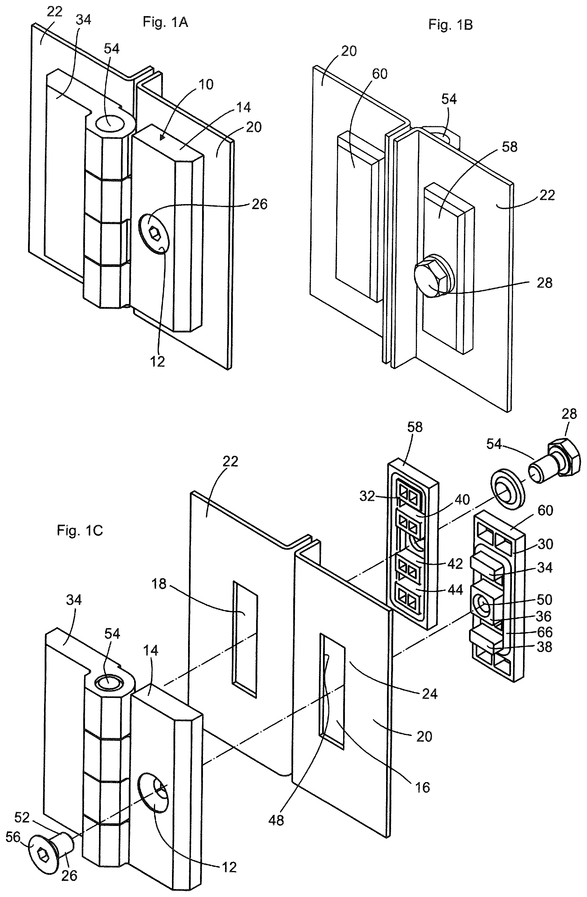
FIG. 1A shows a top view, from outside, of a hinge according to the invention, according to a first embodiment, mounted on a cabinet, in a mounted perspective representation,
FIG. 1B shows a rear view of the hinge from FIG. 1A,
FIG. 1C shows a pulled-apart representation of the hinge according to FIG. 1A;
FIG. 2A shows another embodiment of the hinge according to the invention in a pulled-apart representation,
FIG. 2B shows the hinge from FIG. 2A in a sectional view illustrating the use of an O-ring seal,
FIG. 2C shows a similar embodiment with different arrangement of an O-ring seal,
FIG. 2D shows the unmounted hinge, opened up,
FIG. 2E shows a sectional view along the contact plane of one hinge part,
FIG. 2F shows an axial sectional view through one fixing possibility by means of a countersunk screw,
FIG. 2G shows a similar representation to FIG. 2F, but with inserted O-ring seal,
FIG. 2H shows a sectional view along the contact plane of the further embodiment,
FIG. 2I shows an axial sectional view illustrating the adjustability in an axial direction,
FIG. 2J shows the embodiment according to FIG. 2I, but with O-ring seal;
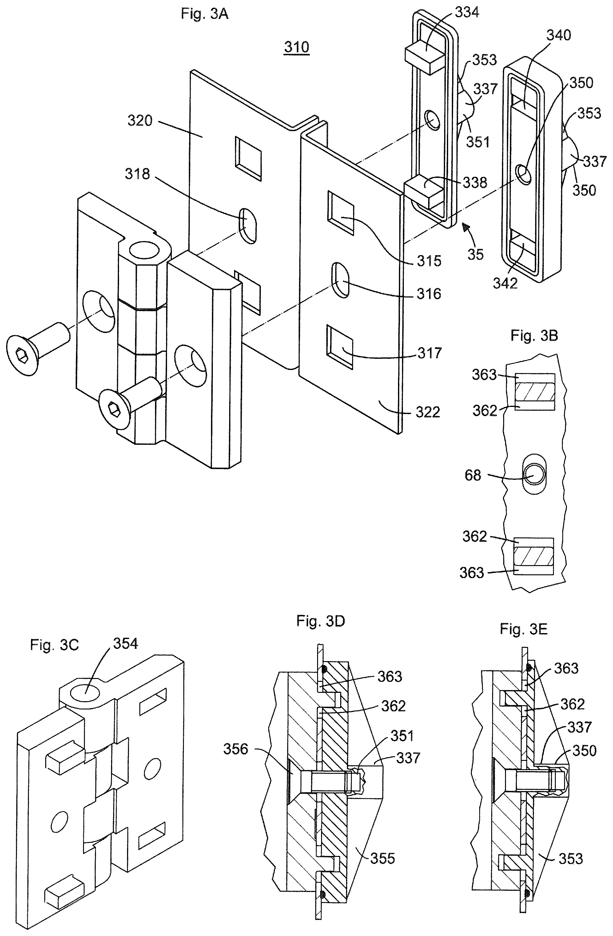
FIG. 3A shows a further embodiment of the hinge according to the invention in a pulled-apart representation,
FIG. 3B shows a sectional view along the contact surface of the leaf provided with projections;
FIG. 3C shows a representation of the opened unmounted hinge,
FIG. 3D shows a representation of the opened unmounted hinge,
FIG. 3E shows a corresponding representation of the other leaf;
FIG. 4A shows a further embodiment of the hinge according to the invention in a pulled-apart representation,
FIG. 4B shows a representation of the unmounted hinge in opened position,
FIG. 4C shows an axial representation of the section through one leaf,
FIG. 4D shows a corresponding representation through the other leaf; and
FIG. 5A shows an application of the hinge according to the invention with the possibility of adjustment in two dimensions.
DESCRIPTION OF THE INVENTION
FIG. 1A shows a hinge system 10 viewed obliquely from the outside, consisting of a hinge leaf 14 with a bore 12, said hinge system being suitable for fixing in an elongated opening 16, see the pulled-apart representation of the hinge according to FIG. 1C, or alternatively in several openings arranged in a row, see reference numbers 316, 315, 317 in FIG. 3A, reference numbers 416, 415, 417 in FIG. 4A and reference numbers 517, 516 in FIG. 5A. The opening 16 in the thin wall 20 has marginal surfaces 24 against which the hinge leaves of the hinge 10 breakthrough come to lie. The two retaining surfaces 30, 32 lying against the marginal surfaces 24 are pressed together by means of a screwed connection 26 or 28, wherein projections 34, 36, 38 extend from the hinge leaves 14, 34 or the plate 30, 32 in the region of the breakthrough 16 or 18 which extend into or through the breakthroughs 16, wherein recesses 40, 42, 44 are formed in the plate or the hinge leaves 14, 32 to receive the projections 34, 36, 38, wherein the projections are guided by the surfaces 48 of the inner edges 48 of the breakthroughs 16, 18.
In particular and according to the invention, the bore 50 is passed through a projection 36 beyond the free end of the screw 26.
The embodiment shown in FIG. 1A to 1C also includes a second leaf 34 which is connected with the first leaf 14 in an articulated manner by means of a hinge pin 54.
The hinge system can be characterised in that the bore 12 for the head end 56 of the screw 26 is passed through the conical recess for a countersunk screw head.
The bore 50 provided with a thread 68 for the free end 26 of the screw can be formed in a tubular section 51, see FIG. 3E, which is reinforced through optional sloping partition walls 353, see FIG. 3A to 3E. The tubular section 353 or 350 thus contains a screw thread.
The projection 36 also contains a threaded bore 50.
As can be seen from FIG. 1C as well as FIGS. 2E and 2H, and as can also be seen from FIG. 2A, the other projections, e.g. 234 in FIG. 2E, form bridges 69, 70 between the two longitudinal edges 248 of the breakthrough 218.
FIGS. 2E, 2F and 2G show that the side surfaces of the projections 69, 70, 276 also form grooves 264 for an O-ring seal 266.
In order to achieve axial adjustability, the rectangular breakthrough permit an axial displacement of the plate 260 and thus the projections on the plate relative to the hinge leaves, see reference numbers 62, 362.
The hinge system can be designed such that the second hinge leaf 34 is analogous or complementary in structure to the first hinge leaf 14.
FIGS. 1A, 1C and 2A for example show complementary hinge leaves 14, 34, 214, 334, whereas FIG. 3A for example shows an analogous arrangement.
FIG. 4A also shows a complementary arrangement in which, however, the arrangement of the screws 426 is analogous for the two leaves.
The further FIGS. 4C and 4D show, as a particularly favourable embodiment, that one screw 426 is arranged with its hexagonal screw head 428 on the outer side of the door, whereas FIG. 4B, 4C and FIG. 4D show a different arrangement.
It serves the purpose of axial adjustability if the projections 334, 338 or recesses 340, 342 arranged at the ends of the longitudinal extension of the rectangular breakthroughs are arranged at a distance 362 from the narrow rectangular edge.
In order to achieve axial and radial adjustability it is favourable if one leaf has a radial orientation of the longitudinal extension of the rectangular breakthrough and the other leaf has an axial orientation.
The projecting dog point of the fixing screw is square or rectangular in design and in the case of thicker metal doors penetrates into the bridge mounted at the back in order to provide security against rotation, even if the projecting outer extensions are shorter and do not reach the inner bridge.
INDUSTRIAL APPLICATION
The invention can be applied commercially in the construction of switchgear cabinets.
LIST OF REFERENCE NUMERALS
10, 110, 210, 310, 410, 510 Hinge system 12, 112, 212, 312, 412, 512 Bore 14, 114, 214, 414, 514 Hinge leaf (first with through-bore) 315 Opening 16, 216, 316, 416, 516 Opening 517 Opening 18, 218, 318, 418, 518 Opening 20, 220, 320, 420 Thin wall, door leaf 22, 222, 322, 422 Thin wall, door frame 24, 224 Marginal surface 26, 226, 426 Screwed connection, end of screw, screw 28, 228, 428 Screwed connection 30 Retaining surface 32 Retaining surface 34, 234, 434 Hinge leaf (second) (with threaded bore) 235 Projection 36, 236 Projection 237, 337, 437, 537 Projection 38, 438 Projection 239 Projection 40, 440 Projection 241 Recess 42, 442 Recess 243 Recess 44 Recess 245 Recess 46 Recess 48, 248 Inside edge of opening, edges 50, 250 Bore 51, 451 Tubular section 52 Free end 353 Partition wall 54, 254, 454 Hinge pin 355, 455 Partition wall 56 Head end 58, 258, 458 Retaining plate (with through-bore) 60, 260, 460 Retaining plate (with threaded bore) 261 Retaining plate 62, 362 Breakthrough extension, play 63,363 Breakthrough extension, play 264 Groove 265 Groove 66, 266 O-ring seal 267 O-ring seal 68 Thread 69 Bridge 70 Bridge
* * * * *
D00000
D00001
D00002
D00003
D00004
D00005
XML
uspto.report is an independent third-party trademark research tool that is not affiliated, endorsed, or sponsored by the United States Patent and Trademark Office (USPTO) or any other governmental organization. The information provided by uspto.report is based on publicly available data at the time of writing and is intended for informational purposes only.
While we strive to provide accurate and up-to-date information, we do not guarantee the accuracy, completeness, reliability, or suitability of the information displayed on this site. The use of this site is at your own risk. Any reliance you place on such information is therefore strictly at your own risk.
All official trademark data, including owner information, should be verified by visiting the official USPTO website at www.uspto.gov. This site is not intended to replace professional legal advice and should not be used as a substitute for consulting with a legal professional who is knowledgeable about trademark law.