Reinforced cable tie strap and method of manufacture
Bednarowski , et al. June 30, 2
U.S. patent number 10,696,459 [Application Number 15/895,525] was granted by the patent office on 2020-06-30 for reinforced cable tie strap and method of manufacture. This patent grant is currently assigned to ABB Schweiz AG. The grantee listed for this patent is ABB Schweiz AG. Invention is credited to Dariusz Bednarowski, Krzysztof Dudek, Kathryn F. Murphy.


| United States Patent | 10,696,459 |
| Bednarowski , et al. | June 30, 2020 |
Reinforced cable tie strap and method of manufacture
Abstract
A reinforced cable tie generally includes an elongate strap having a first end, a second end and an elongate planar strap body therebetween, a head having an upstanding central wall separating a first and a second elongate parallel passageway through the head for respective receipt of the first and second ends of said strap, a locking device supported in the head for retaining the first and second ends of the strap and a continuous reinforcement disposed in and extending substantially continuously along a path defining the strap. In a method for forming a cable tie, a continuous reinforcing strand is co-extruded within an elongate strap and a head is assembled to the strap.
| Inventors: | Bednarowski; Dariusz (Cracow, PL), Murphy; Kathryn F. (South San Francisco, CA), Dudek; Krzysztof (Cracow, PL) | ||||||||||
|---|---|---|---|---|---|---|---|---|---|---|---|
| Applicant: |
|
||||||||||
| Assignee: | ABB Schweiz AG (Baden,
CH) |
||||||||||
| Family ID: | 63106685 | ||||||||||
| Appl. No.: | 15/895,525 | ||||||||||
| Filed: | February 13, 2018 |
Prior Publication Data
| Document Identifier | Publication Date | |
|---|---|---|
| US 20180229906 A1 | Aug 16, 2018 | |
Related U.S. Patent Documents
| Application Number | Filing Date | Patent Number | Issue Date | ||
|---|---|---|---|---|---|
| 62459676 | Feb 16, 2017 | ||||
| Current U.S. Class: | 1/1 |
| Current CPC Class: | B32B 27/286 (20130101); B32B 5/024 (20130101); B32B 19/045 (20130101); B32B 27/288 (20130101); B32B 37/153 (20130101); B32B 27/306 (20130101); B32B 27/08 (20130101); B65D 63/16 (20130101); B65D 63/08 (20130101); B32B 27/34 (20130101); B32B 27/322 (20130101); B32B 27/36 (20130101); B29C 48/345 (20190201); B32B 5/02 (20130101); B32B 27/285 (20130101); B29C 48/08 (20190201); B32B 3/04 (20130101); B32B 27/281 (20130101); B29C 48/154 (20190201); B32B 27/365 (20130101); B32B 27/12 (20130101); B32B 27/32 (20130101); B32B 27/304 (20130101); B32B 2307/54 (20130101); B32B 2553/00 (20130101); B32B 2262/101 (20130101); B32B 2250/02 (20130101); B32B 2250/03 (20130101); B32B 2307/548 (20130101); B29C 48/2883 (20190201); B32B 2262/106 (20130101); B32B 2305/08 (20130101); B65D 2563/103 (20130101); B32B 2307/30 (20130101); B32B 2307/734 (20130101); B32B 2262/02 (20130101); B32B 2262/14 (20130101); B32B 2315/085 (20130101); B32B 2262/10 (20130101); B29K 2105/106 (20130101); B32B 2377/00 (20130101); B29K 2101/12 (20130101) |
| Current International Class: | B65D 63/08 (20060101); B32B 27/12 (20060101); B32B 27/34 (20060101); B32B 37/15 (20060101); B32B 5/02 (20060101); B29C 48/30 (20190101); B65D 63/16 (20060101); B29C 48/345 (20190101); B29C 48/154 (20190101); B29C 48/08 (20190101); B29C 48/285 (20190101) |
References Cited [Referenced By]
U.S. Patent Documents
| 3241184 | March 1966 | Barnett |
| 3367814 | February 1968 | Weiner et al. |
| 3913179 | October 1975 | Rhee |
| 3979493 | September 1976 | Cameron et al. |
| 4394338 | July 1983 | Fuwa |
| 4588538 | May 1986 | Chung et al. |
| 4599126 | July 1986 | Duffield |
| 5096645 | March 1992 | Fink |
| 5268050 | December 1993 | Azari |
| 5595696 | January 1997 | Schlarb et al. |
| 5779961 | July 1998 | Teutsch |
| 5976627 | November 1999 | Wynne |
| 6128809 | October 2000 | Khokhar |
| 6863855 | March 2005 | Shilale |
| 7402268 | July 2008 | Boissonnat et al. |
| 7730592 | June 2010 | Krisel |
| 8230555 | July 2012 | Browne |
| 2003/0057590 | March 2003 | Loher et al. |
| 2004/0098841 | May 2004 | Crosby et al. |
| 2012/0180270 | July 2012 | Marmelstein |
| 2013/0298353 | November 2013 | Drane et al. |
| 2014/0020229 | January 2014 | Moore |
| 2014/0059809 | March 2014 | Gao |
| 2015/0064437 | March 2015 | Luo et al. |
| 2015/0101152 | April 2015 | Gao |
| 2018/0282037 | October 2018 | Zant |
| 201249930 | Jun 2009 | CN | |||
| 202400427 | Aug 2012 | CN | |||
| 203497387 | Mar 2014 | CN | |||
| WO0124993 | Apr 2001 | WO | |||
Other References
|
PCT Application No. PCT/US16/27509. cited by applicant . Canadian Intellectual Property Office, Requisition by the Examiner issued in corresponding Canadian application No. 2,994,583, dated Dec. 13, 2018, 5 pp. cited by applicant . Canadian Intellectual Property Office, Requisition by the Examiner issued in corresponding Canadian application No. 2,994,583, dated Nov. 4, 2019, 6 pp. cited by applicant. |
Primary Examiner: Sandy; Robert
Attorney, Agent or Firm: Taft Stettinius & Hollister LLP Schelkopf; J. Bruce
Parent Case Text
CROSS-REFERENCE TO RELATED APPLICATIONS
This application claims priority from U.S. provisional application Ser. No. 62/459,676, filed on Feb. 16, 2017, the specification of which is incorporated herein in its entirety for all purposes.
Claims
What is claimed is:
1. A cable tie comprising: an elongate strap having a first end, a second end and an elongate planar strap body therebetween; a head having an upstanding central wall separating a first and a second elongate parallel passageway through said head for respective receipt of said first and second ends of said strap; a locking device supported by said central wall, said locking device being configured to permit said first and second ends of said strap to be respectively inserted through said first and second passageways of said head in a first direction and being further configured to prevent movement of said first and second ends of said strap from said respective head passageways in a second direction opposite said first direction; and a continuous reinforcement disposed in and extending substantially continuously along a path defining said strap, wherein said head comprises a continuous fiber reinforcement structure and is separately attachable to said strap.
2. The cable tie as defined in claim 1, wherein said continuous reinforcement is co-extruded with said strap.
3. The cable tie as defined in claim 1, wherein said continuous reinforcement comprises a glass fiber.
4. The cable tie as defined in claim 1, wherein said continuous reinforcement comprises a metallic strand.
5. The cable tie as defined in in claim 1, wherein said continuous reinforcement is disposed centrally within said strap.
6. The cable tie as defined in claim 1, wherein said continuous reinforcement comprises glass, aramid, carbon, metal, basalt, polybenzimidazole, natural fibers, carbon nanotubes, graphene, or any combination thereof.
7. The cable tie as defined in claim 1, wherein said continuous reinforcement comprises bundles of filaments, twisted cords, twisted ropes, single filaments, woven sheets, tapes, meshes, ladder-like structures or perforated sheets.
8. The cable tie as defined in claim 1, wherein said head is attachable to said strap during installation of the cable tie.
9. The cable tie as defined in claim 1, wherein said strap comprises an extrudable thermoplastic.
10. The cable tie as defined in claim 9, wherein said extrudable thermoplastic comprises nylon, acetal, or polypropylene.
11. The cable tie as defined in claim 1, wherein a percentage by weight of said continuous reinforcement content with respect to said strap is between 1% and 30%.
12. The cable tie as defined in claim 1, wherein the overall thickness of the strap and the continuous reinforcement disposed therein is between 0.3 mm and 3 mm.
Description
TECHNICAL FIELD
The present invention relates to cable ties having improved mechanical strength and creep resistance. More particularly, the present invention is directed to a strap for a cable tie having a continuous reinforcement co-extruded with the strap.
BACKGROUND
A cable tie or tie-wrap, also known as a hose tie, zap-strap or zip tie, is a type of fastener for holding items together, such as electric cables or wires. Because of their low cost and ease of use, tie-wraps are ubiquitous, finding use in a wide range of other applications. Stainless steel versions, either naked or coated with a rugged plastic, cater to exterior applications and hazardous environments.
The common tie-wrap, normally made of nylon, has a strap section with teeth that engages with a pawl in a head to form a ratchet so that, as the free end of the strap is pulled, the tie-wrap tightens and does not come undone. Another version of the tie-wrap allows a tab to be depressed to either adjust the tension or remove the tie-wrap. Another popular design of the cable tie locking mechanism involves a metallic barb in the head slot. The metallic, e.g. stainless steel, barb is inserted after the plastic part is molded. The barb engages and cuts into the strap surface to lock the strap in place when fastened.
Another prior-art design of a tie-wrap is assembled from a plastic strap component and a double lock head component. The plastic strap is extruded continuously and the head is fabricated separately and subsequently assembled to the strap. The double lock head has two slots with a metal barb in each slot to lock the plastic strap inserted into the head. The plastic material in this design is typically acetal.
This separate head and strap design is favored by industries, such as telecommunications, for securing large bundles of cables. The customer purchases strap material supplied on a reel, cuts a strap to a desired length, and secures the cut length of strap with a separate locking head comprising two metal barbs within a plastic housing.
A typical requirement for cable ties, in addition to, for example, chemical resistance to common automotive fluids, is that a fastened cable tie should withstand prolonged exposure to elevated temperatures, (e.g. at 125.degree. C.), if it is to be applied, for example, in or in the vicinity of the engine compartment. At the same time, such a cable tie should show good mechanical strength at low, (e.g. sub-zero), temperatures. For such high-end applications, cable ties are often molded from a polyamide composition, (e.g. a plasticized polyamide 11 composition, an elastomer-modified polyamide 66 composition, etc.). Acetal material is also used to extrude cable tie straps and injection mold cable tie heads separately due to its relatively inferior processability.
A cable tie has several typical failure mechanisms. First, the cable tie strap can break when the fastening load is beyond the material strength limit. Another failure mechanism involves the unlocking of the strap from the cable tie head slot, whether the cable tie uses a plastic pawl or a metallic barb. Still another failure relates to creep, leading to loosening of cable bundles over time. Each failure mechanism can cause a cable tie to fail before reaching its designated loop tensile strength rating.
Since the original invention of the cable tie in 1958, many follow-up patents have emerged that mainly focus on improved manufacturing methods, new materials, or special applications. For example, for applications requiring high strength, stiffness, and environmental resistance, stainless steel cable ties have been developed. However, in many applications a nonmetallic solution is desired. Moreover, such stainless steel cable ties can be sharp, heavy, and may interfere with RF signals.
In such applications, more recent patents focus on reinforcing of the polymer matrix with graphene. Another prior art method of reinforcement involves introducing strengthening fibers into the raw plastic material prior to molding the cable tie. However, such reinforced plastics, when bought from a material supplier, tend to have a higher price than unreinforced plastics due to the additional step of compounding required during their manufacture. Such materials will furthermore increase the overall stiffness of the cable tie, rendering it incapable of being easily bent to form a loop.
It is also known from commonly owned PCT Application No. PCT/US16/27509 to form cable ties with a continuous glass reinforcing fiber positioned within the strap and/or head during an injection molding process. However, injection molding over glass fibers can be difficult to implement in a factory.
Accordingly, it would be desirable to provide a simple, inexpensive method for reinforcing the strength of a cable tie.
SUMMARY
In one aspect of the present invention, a reinforced cable tie strap is provided, wherein the cable tie strap is co-extruded with a continuous reinforcement throughout the whole body. In another aspect of the invention, a manufacturing method for providing reinforcement of a standard cable tie is provided. This type of reinforcement allows for a whole family of polymer matrices to be used.
The reinforced cable tie strap forms part of a cable tie including a head having an upstanding central wall separating a first and second elongate parallel passageways through the head for respective receipt of a first and a second end of the strap and a locking device supported by the central wall, wherein the locking device is configured to permit the first and second ends of the strap to be respectively inserted through the first and second passageways of the head in a first direction and being further configured to prevent movement of the first and second ends of the strap from the respective head passageways in a second direction opposite said first direction.
The continuous reinforcement may comprise a glass fiber or a steel strand. The continuous reinforcement may comprise glass, aramid, carbon, metal, basalt, polybenzimidazole, natural fibers, or any combination thereof. The continuous reinforcement may comprise bundles of filaments, twisted cords, twisted ropes, single filaments, woven sheets, tapes, or meshes. The continuous reinforcement may further comprise structures with ladder-like or perforated sheet geometry and may also be made of carbon nanotubes or graphene.
The strap may comprise any thermoplastic material, such as nylon, acetal, or polypropylene. The percentage by weight of the continuous reinforcement content with respect to the strap is preferably between 1% and 30%.
The head is separately attachable to the strap. This can occur during installation of the cable tie or the head can also be attached to one side in the factory.
The overall thickness of the strap and the continuous reinforcement disposed therein is preferably between 0.3 mm and 3 mm and the continuous reinforcement is preferably disposed centrally within the strap.
In another aspect of the present invention, a method for forming a cable tie is provided. The method generally includes co-extruding a continuous reinforcing strand within an elongate strap and assembling a head to the strap, wherein the head has an upstanding central wall separating a first and a second elongate parallel passageway through the head for respective receipt of a first and second ends of said strap and a locking device supported by said central wall, said locking device being configured to permit said first and second ends of said strap to be respectively inserted through said first and second passageways of said head in a first direction and being further configured to prevent movement of said first and second ends of said strap from said respective head passageways in a second direction opposite said first direction.
The step of co-extruding preferably includes conveying the continuous reinforcing strand through a first passage of a first die part of a co-extrusion die, injecting a thermoplastic through a second passage of the first die part of the co-extrusion die such that the injected thermoplastic encapsulates the continuous reinforcing strand and passing the injected thermoplastic with the continuous reinforcing strand encapsulated therein through a passage of a second die part of the co-extrusion die, wherein the second die part forms the final profile of the strap.
The second passage of the first die part is preferably configured for injecting the thermoplastic at a finite angle with respect to the continuous reinforcing strand. The first and second passages of the first die part are also preferably configured to centrally dispose the continuous reinforcing strand within the strap.
In another method for forming a cable tie, continuous fibers are co-extruded with a plastic material to form a strip with continuous fibers incorporated along its length and a cable tie is subsequently formed by compression molding of the strip or by supporting the strip in a mold cavity of a mold. The mold cavity has a size and shape of a cable tie including a head having an aperture.
As a result of either method, a cable tie with continuous reinforcements located at or near the center plane of the strap is provided. The reinforcements make the strap much stronger and more creep resistant than an unreinforced strap. By locating the reinforcements at the center plane, the strap remains compliant in bending so that a user can form a loop. Both methods ensure the reinforcements are correctly placed during the extrusion process.
The present invention provides substantial business benefits. For example, the method of the present invention achieves the reinforcement during the manufacture of the cable tie strap and thus eliminates one step during material production.
Also the invention bears great flexibility in the sense that it works with many different polymer matrices and types of fibers and therefore can be applied in many different market segments.
Features of the disclosure will become apparent from the following detailed description considered in conjunction with the accompanying drawings. It is to be understood, however, that the drawings are designed as an illustration only and not as a definition of the limits of this disclosure.
BRIEF DESCRIPTION OF THE DRAWINGS
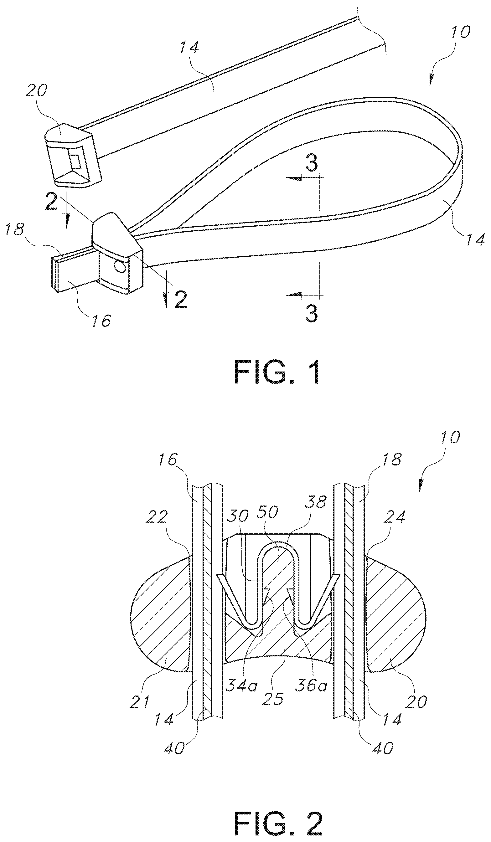
FIG. 1 is a perspective view of two cable ties according to the present invention.
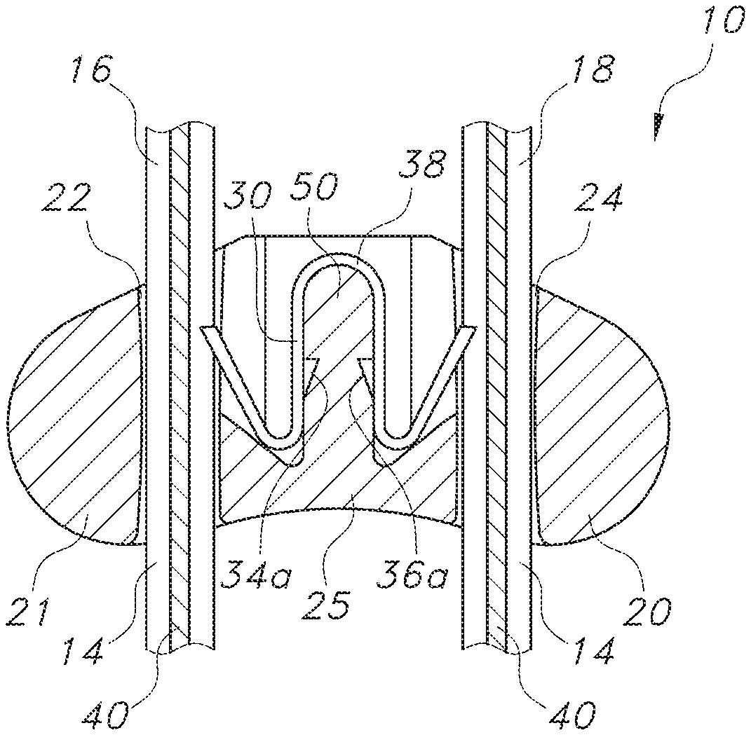
FIG. 2 is a cross-sectional view of one of the cable ties shown in FIG. 1, taken along line 2-2.
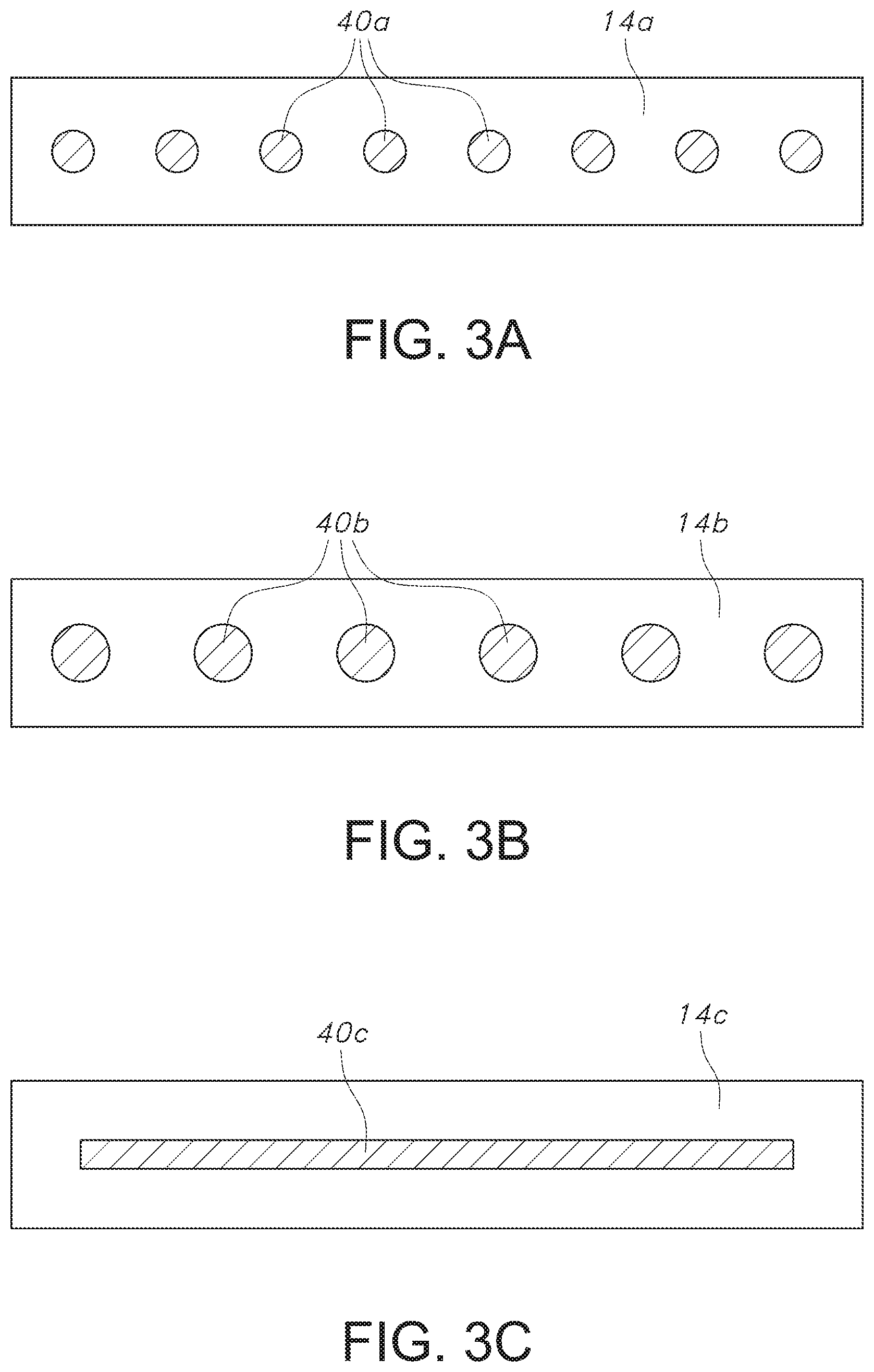
FIGS. 3a, 3b and 3c are respective cross-sectional views of alternative embodiments of one of the cable straps shown in FIG. 1, taken along line 3-3.
FIG. 4 is a perspective view of a die set for forming a cable tie strap in accordance with the present invention.
FIG. 5 is a cross-sectional view of the die set shown in FIG. 4 assembled and in use according to a method of the present invention.
FIG. 6 is a perspective view of several embodiments of the die set according to the present invention.
FIG. 7 is a plan view of an alternative embodiment of one part of the die set according to the present invention.
DETAILED DESCRIPTION OF PREFERRED EMBODIMENTS
Referring first to FIGS. 1 and 2, the cable tie assembly 10 of the present invention is designed to be looped around a plurality of electrical cables or similar articles which are formed in a bundle (not shown). The cable tie assembly 10 is a two-piece member formed of a high strength material and is suitable for both indoor and outdoor use.
The two-piece construction of cable tie assembly 10 includes an elongate generally planar cable tie strap 14 having opposed ends 16 and 18 which are designed to be looped around the cable bundle. The cable tie strap 14 typically has a generally rectangular cross-sectional configuration, although other shapes may be employed.
The ends 16 and 18 of strap 14 may be secured within a separately formed head 20 of the cable tie assembly 10. The head 20 includes a body 21 having a pair of spaced apart side-by-side parallel passageways 22 and 24 extending therethrough for accommodating respectively the ends 16 and 18 of strap 14 when inserted in the direction of arrow A defining an insertion direction. The body 21 includes a central supporting structure 25, which supports a strap locking device 30.
The locking device 30 is supported by the central supporting structure 25 and includes a body having a central joining section 38 and a pair of parallel walls 34a and 36a extending from the joining section. The locking device is an integrally formed metallic member preferably formed of a copper alloy exhibiting sufficient rigidity yet is relatively resiliently deflectable. The locking device further includes a first barb extending from one of the wall members into the first passageway and a second barb extending from the other wall member into the second passageway. The barbs are provided for independent deflectable locking engagement with the first and second strap ends upon insertion into the passageways. A typical head, including locking device, for use with the strap 14 of the present invention is shown and described in commonly owned U.S. Pat. No. 6,128,809, the specification of which is incorporated herein in its entirety for all purposes.
Referring specifically to FIG. 2, and as will be described in further detail below, a continuous reinforcement structure 40 is provided in the strap 14 as a result of a co-extrusion process according to the present invention. The continuous reinforcement structure 40 is co-extruded along the full length of the strap 14.
In one aspect of the present invention, straps can be formed with multiple strands of glass fibers (1200 tex). Thus, for example, FIG. 3a shows a cross-section of a strap 14a with 8 strands of glass fiber 40a.
In another aspect of the present invention, straps can be formed with multiple ropes of steel. Thus, for example, FIG. 3b shows a strap 14b with 6 ropes of steel 40b (1.times.7 construction with overall diameter 0.63 mm).
In still another aspect of the present invention, straps can be formed with a reinforcing layer made from fiber or metallic materials. Thus, for example, FIG. 3c shows a strap 14c with a pressed glass fiber fabric sheet 40c.
In each of the embodiments shown in FIGS. 3a, 3b and 3c, the base material matrix of the strap is nylon (PA66), though it would be straightforward to use other thermoplastics to suit the application. However, changes to the reinforcements 40a, 40b, 40c may require changes to the die, (described later below).
The placement of the reinforcements inside the strap is not trivial. Typical glass fiber reinforced plastic articles have a nominally homogeneous distribution of fibers. To accurately position the reinforcements, the present invention provides a process wherein the plastic material is extruded above and below the reinforcing strands, which are pulled through the extrusion die crosshead. This co-extrusion of plastic and reinforcing strands requires the application of a special die and crosshead designed for the strand material and cross section.
Turning now to FIGS. 4 and 5, the co-extrusion die 50 of the present invention generally includes two parts 52, 54. The first part 52 has a centrally located channel or channels 56 to allow passage of the reinforcements 40a,b,c, with separate channels 58 on opposite sides of the reinforcement channels to allow for passage of the plastic melt 15. The channels 58 for the plastic melt should preferably be of equal cross sections. The second part 54 of the die is a typical standard extrusion die having an exit channel 60, which forms the final profile of the cable tie strap 14a,b,c.
FIGS. 6 and 7 show several variations of the first part of the die in the form of a six strand die 52a, a four strand die 52b, a no strand die 52c and a three flat strand die 52d. Also shown in FIG. 5 is the second part 54 of the die termed a "final profile" die.
In the case of glass fiber or other delicate reinforcements, the die should be heat treated and polished, and edges should be rounded to avoid filament breakage. Separate channels could be used for each strand, or a single wide channel for all strands. A tapered channel which becomes narrower toward the outlet is preferred to reduce friction on the strands.
The crosshead should allow for extrusion in a direction not parallel to the cylinder's axis. This allows for the reinforcements to enter and leave the crosshead without having to turn a corner inside the head. Since the plastic melt is liquid, the precise angle at which it enters and leaves the crosshead is relatively unimportant.
The strap extruded in this manner will typically be wound on a reel for later use as part of a cable tie. When needed, the strap is unwound from the reel and a suitable length is cut. A head is then fastened to the cut length to form a cable tie, as described above. However, given the reinforcing structure extruded centrally within the strap, care must be taken when fastening the head to avoid cutting or otherwise damaging the reinforcing structure. A specially designed head for use with co-extruded straps of the present invention is preferably provided.
Glass fiber roving and steel ropes have been demonstrated, but other materials and forms should be considered. Of particular interest are metal meshes and twisted glass cords. Moreover, the reinforcements can be pre-treated with various coatings to improve adhesion with the matrix. Also, it is conceivable that the reinforcing glass strands can be impregnated with a polymer to form a tape, and then have plastic extruded on either side. Reinforcing strands could also be "worked" when inside the plastic melt to improve impregnation. This could be done by running the fibers over rollers or around pins within the melt.
The term "continuous fiber" is used herein to refer to a reinforcing strand, or roving, or filament structure that is contiguous and unbroken along its length extending along a desired path. Unlike fiber reinforcing methods of the past, the continuous fiber is placed in the cable tie only where needed. Suitable materials for the continuous fiber include glass, aramid, carbon, metal, basalt, polybenzimidazole, natural fibers, etc.
For the polymer matrix, different thermoplastic materials suitable for extrusion could be used, (e.g., PA, POM, PBT, ETFE, PP, etc.). Thus, suitable base plastics include, but are not limited to, polyamide (e.g., nylon), polypropylene, polycarbonate, poly(ethylene tetrafluoroethylene), polyetheretherketone, poly(ethylene and chlorotrifluoroethylene), polyvinyl chloride, polyimide, polysulfone, and combinations of two or more thereof. Suitable base plastic materials may also include thermosets. In one embodiment, the base plastic is polypropylene. In one embodiment, the base plastic is polyamide. In one embodiment, the base plastic is polyamide 6 (i.e., nylon 6). In one embodiment, the base plastic is polyamide 6,6 (i.e., nylon 6,6). In one embodiment, base plastic is polyamide 6,6 loaded at between about 90-100 phr. In one embodiment, polyamide 6,6 is loaded at about 100 phr. In one embodiment, polyamide 6,6 loaded at about 100 phr is a medium impact modified compound with embedded process aid. In one embodiment, polyamide 6,6 loaded at about 100 phr is an unfilled resin with embedded process aid.
As a result of the present invention, a continuous cable tie strap comprising an extruded thermoplastic with continuous reinforcing strands embedded near the center plane is provided. The strap itself is significantly stronger and more creep resistant than an unreinforced strap. By placing the reinforcements close to the center plane rather than distributing them throughout the cross section, the strap is stronger and stiffer in tension, yet still compliant in bending so that it can easily form a loop.
Thus, a tailored reinforced cable tie is provided having the following benefits: 1) Improved form stability at higher temperatures; 2) Lower tendency to creep; 3) Increased light-weight potential due to high weight-specific mechanical properties; 4) Wider choices of plastic materials, e.g. with lower mechanical properties/cost; 5) Improved cable tie structural integrity by reducing the chance for a plastic pawl to yield or break.
It should be apparent to those skilled in the art that the described embodiments of the present invention provided herein are illustrative only and not limiting, having been presented by way of example only. As described herein, all features disclosed in this description may be replaced by alternative features serving the same or similar purpose, unless expressly stated otherwise. Therefore, numerous other embodiments of the modifications thereof are contemplated as falling within the scope of the present invention as defined herein and equivalents thereto. While various embodiments of the present invention are specifically illustrated and/or described herein, it will be appreciated that modifications and variations of the present invention may be effected by those skilled in the art without departing from the spirit and intended scope of the invention.
All documents, patents and other literature referred to herein are incorporated by reference in their entirety.
The term "comprising" as may be used in the following claims is an open-ended transitional term that is intended to include additional elements not specifically recited in the claims. The term "consisting essentially of" as may be used in the following claims is a partially closed transitional phrase and is intended to include the recited elements plus any unspecified elements that do not materially affect the basic and novel characteristics of the claims. For example, the cable tie may be embossed or printed with indicia and still be included in the meaning of "consisting essentially of", even if not specifically recited. The term "consisting of" as may be used in the following claims is intended to indicate that the claims are restricted to the recited elements.
It should be noted that it is envisioned that any feature, element or limitation that is positively identified in this document may also be specifically excluded as a feature, element or limitation of an embodiment of the present invention.
* * * * *
D00000
D00001
D00002
D00003
D00004
XML
uspto.report is an independent third-party trademark research tool that is not affiliated, endorsed, or sponsored by the United States Patent and Trademark Office (USPTO) or any other governmental organization. The information provided by uspto.report is based on publicly available data at the time of writing and is intended for informational purposes only.
While we strive to provide accurate and up-to-date information, we do not guarantee the accuracy, completeness, reliability, or suitability of the information displayed on this site. The use of this site is at your own risk. Any reliance you place on such information is therefore strictly at your own risk.
All official trademark data, including owner information, should be verified by visiting the official USPTO website at www.uspto.gov. This site is not intended to replace professional legal advice and should not be used as a substitute for consulting with a legal professional who is knowledgeable about trademark law.