Composite pallet
Hawley , et al. June 30, 2
U.S. patent number 10,696,449 [Application Number 15/989,427] was granted by the patent office on 2020-06-30 for composite pallet. This patent grant is currently assigned to INTEGRATED COMPOSITE PRODUCTS, INC.. The grantee listed for this patent is INTEGRATED COMPOSITE PRODUCTS, INC.. Invention is credited to Ronald C. Hawley, Derek J. Mazula.


View All Diagrams
| United States Patent | 10,696,449 |
| Hawley , et al. | June 30, 2020 |
Composite pallet
Abstract
Composite pallets and methods for making and using composite pallets are disclosed. An example composite pallet may include a base layer. The base layer may include a first base board, a second base board, and a cross-member extending between the first base board and the second base board. The cross-member may include a first end region designed to be detachably coupled to the first base board, a second end region designed to be detachably coupled to the second base board, and at least one curved section positioned between the first end region and the second end region. The cross-member may include a polymer. An intermediate layer may be coupled to the base layer. The intermediate layer may include a plurality of intermediate boards. A top layer may be coupled to the intermediate layer. The top layer may include a plurality of top boards.
| Inventors: | Hawley; Ronald C. (Winona, MN), Mazula; Derek J. (Sioux Falls, SD) | ||||||||||
|---|---|---|---|---|---|---|---|---|---|---|---|
| Applicant: |
|
||||||||||
| Assignee: | INTEGRATED COMPOSITE PRODUCTS,
INC. (Rochester, MN) |
||||||||||
| Family ID: | 62621043 | ||||||||||
| Appl. No.: | 15/989,427 | ||||||||||
| Filed: | May 25, 2018 |
Prior Publication Data
| Document Identifier | Publication Date | |
|---|---|---|
| US 20180339803 A1 | Nov 29, 2018 | |
Related U.S. Patent Documents
| Application Number | Filing Date | Patent Number | Issue Date | ||
|---|---|---|---|---|---|
| 62511759 | May 26, 2017 | ||||
| Current U.S. Class: | 1/1 |
| Current CPC Class: | B65D 19/0095 (20130101); B65D 19/0073 (20130101); B65D 2519/00014 (20130101); B65D 2519/00373 (20130101); B65D 2519/0099 (20130101); B65D 2519/00378 (20130101); B65D 2519/00139 (20130101); B65D 2519/00293 (20130101); B65D 2519/00333 (20130101); B65D 2519/00308 (20130101); B65D 2519/00572 (20130101); B65D 2519/00104 (20130101); B65D 2519/00781 (20130101); B65D 2519/00069 (20130101); B65D 2519/00447 (20130101); B65D 2519/00034 (20130101); B65D 2519/00323 (20130101); B65D 2519/00368 (20130101); B65D 2519/00412 (20130101); B65D 2519/00273 (20130101); B65D 2519/00407 (20130101); B65D 2519/00049 (20130101); B65D 2519/00437 (20130101); B65D 2519/00417 (20130101); B65D 2519/00442 (20130101) |
| Current International Class: | B65D 19/00 (20060101) |
| Field of Search: | ;108/51.11,57.25,57.27,57.29,901,902 ;206/386,595-600 |
References Cited [Referenced By]
U.S. Patent Documents
| 3199469 | August 1965 | Sullivan |
| 3307504 | March 1967 | Cloyd et al. |
| 4240358 | December 1980 | Munroe |
| 4292900 | October 1981 | Bula |
| 5351628 | October 1994 | Breezer |
| 5483899 | January 1996 | Christie |
| 5492069 | February 1996 | Alexander et al. |
| 5887529 | March 1999 | John |
| 6651815 | November 2003 | Koefelda |
| 6745703 | June 2004 | Torrey et al. |
| 7487730 | February 2009 | Hedstrom |
| 7516705 | April 2009 | Hedstrom |
| 7779764 | August 2010 | Naidu et al. |
| 7874256 | January 2011 | Muirhead |
| 7878127 | February 2011 | Hedstrom |
| 8006629 | August 2011 | Naidu |
| 8141500 | March 2012 | Naidu et al. |
| 8261673 | September 2012 | Ingham |
| 8627773 | January 2014 | Storteboom et al. |
| 8667905 | March 2014 | Anderson et al. |
| 8800456 | August 2014 | Storteboom et al. |
| 8850993 | October 2014 | Storteboom et al. |
| 9340320 | May 2016 | Brandt et al. |
| 9409673 | August 2016 | Brandt et al. |
| 9434506 | September 2016 | Takyar |
| 9745098 | August 2017 | Takyar et al. |
| 9776762 | October 2017 | De Beer et al. |
| 9802732 | October 2017 | Clark |
| D824133 | July 2018 | Hawley et al. |
| 2003/0233963 | December 2003 | Fan |
| 2004/0000259 | January 2004 | Taft |
| 2005/0056193 | March 2005 | Laender et al. |
| 2006/0201402 | September 2006 | Moore, Jr. |
| 2010/0199891 | August 2010 | Miller |
| 2010/0206200 | August 2010 | Tosse |
| 2010/0229764 | September 2010 | Ingham |
| 2013/0153452 | June 2013 | Storteboom |
| 2015/0151506 | June 2015 | Hawley et al. |
| 2017/0232703 | August 2017 | Hawley et al. |
| 2018/0043643 | February 2018 | Hawley et al. |
| 2018/0215505 | August 2018 | Hawley et al. |
| 0801001 | Oct 1997 | EP | |||
| 2564430 | Nov 1985 | FR | |||
| 2449374 | Nov 2008 | GB | |||
| S4945239 | Apr 1974 | JP | |||
| 9422728 | Oct 1994 | WO | |||
| 9511167 | Apr 1995 | WO | |||
| 2005102853 | Nov 2005 | WO | |||
| 2012012367 | Jan 2012 | WO | |||
| 2013154415 | Oct 2013 | WO | |||
Other References
|
International Search Report and Written Opinion dated Aug. 9, 2018 for International Application No. PCT/US2018/034573. cited by applicant. |
Primary Examiner: Wilkens; Janet M
Attorney, Agent or Firm: Seager, Tufte & Wickhem, LLP
Parent Case Text
CROSS-REFERENCE TO RELATED APPLICATIONS
This application claims priority to U.S. Provisional Application Ser. No. 62/511,759, filed May 26, 2017, the entirety of which is incorporated herein by reference.
Claims
What is claimed is:
1. A composite pallet, comprising: a base layer including a first base board, a second base board, and a cross-member extending between the first base board and the second base board; wherein the cross-member includes a first end region designed to be detachably coupled to the first base board, a second end region designed to be detachably coupled to the second base board, and at least one curved section positioned between the first end region and the second end region; wherein the cross-member includes a polymer; an intermediate layer coupled to the base layer, the intermediate layer including a plurality of intermediate boards; a top layer coupled to the intermediate layer, the top layer including a plurality of top boards; and wherein the top layer includes a first end board having a top surface, a bottom surface, and a plurality of longitudinal ribs disposed along the bottom surface.
2. The composite pallet of claim 1, wherein the first base board has a first central region, wherein the second base board has a second central region, wherein the first end region of the cross-member is attached to the first central region, and wherein the second end region of the cross-member is attached to the second central region.
3. The composite pallet of claim 1, wherein the cross-member has a central region and wherein the at least one curved section extends between the first end region and the central region.
4. The composite pallet of claim 3, wherein the cross-member includes a second curved region extending between the central region and the second end region.
5. The composite pallet of claim 3, wherein the first base board and the second base board are designed to lie within a plane, wherein a region of the cross-member lies within the plane, and wherein the at least one curved section curves out from the plane.
6. The composite pallet of claim 1, further comprising a wear pad coupled to the first base board.
7. The composite pallet of claim 1, further comprising a plurality of support blocks that are positioned between the base layer and the intermediate layer.
8. The composite pallet of claim 7, wherein a push support member is coupled to at least one of the plurality of support blocks.
9. The composite pallet of claim 1, wherein the plurality of top boards includes a second end board.
10. The composite pallet of claim 9, wherein the plurality of top boards include a structural board positioned between the first end board and the second end board.
11. The composite pallet of claim 10, wherein the top layer includes a first panel disposed between the first end board and the structural board.
12. The composite pallet of claim 11, wherein the top layer includes a second panel disposed between the second end board and the structural board.
13. The composite pallet of claim 1, wherein the first base board includes a longitudinal axis and wherein the first base board includes plurality of longitudinal ribs extending along the longitudinal axis.
14. The composite pallet of claim 13, wherein the first base board includes a plurality of transverse ribs extending between two or more adjacent longitudinal ribs.
15. The composite pallet of claim 1, wherein the first base board, the second base board, or both include a tension member, a structural member, an impact member, or a combination thereof.
16. The composite pallet of claim 1, wherein at least one of the plurality of intermediate boards include a tension member, a structural member, an impact member, or a combination thereof.
17. The composite pallet of claim 1, wherein the plurality of intermediate boards includes a first intermediate board, wherein the first intermediate board includes a top surface, and wherein a top-side rib is disposed along the top surface.
18. The composite pallet of claim 1, wherein at least one of the plurality of top boards include a tension member, a structural member, an impact member, or a combination thereof.
19. A composite pallet, comprising: a base layer including a plurality of base boards; an intermediate layer detachably coupled to the base layer, the intermediate layer including a plurality of intermediate boards; a plurality of support blocks disposed between the base layer and the intermediate layer; a top layer detachably coupled to the intermediate layer, the top layer including a first end board, a second end board, a structural board positioned between the first end board and the second end board, and a first panel disposed between the structural board and the first end board; wherein the first end board includes a longitudinal rib and a tension member disposed within the longitudinal rib; and wherein at least one of the first end board, the second end board, the structural board, and the first panel include a polymer.
20. A composite pallet, comprising: a base layer including a first base board and a second base board; a cross-member extending between the first base board and the second base board; wherein the cross-member includes one or more curved sections; wherein the cross-member includes a polymer; a support block detachably coupled to the first base board, the second base board, or both; an intermediate layer detachably coupled to the base layer, the intermediate layer including an intermediate board coupled to the support block; a top layer detachably coupled to the intermediate layer, the top layer including a first end board, a second end board, a structural board positioned between the first end board and the second end board, a first panel disposed between the structural board and the first end board, and a second panel disposed between the structural board and the second end board; and wherein the structural board includes a top surface, a bottom surface, and a structural member disposed adjacent to the bottom surface, the structural member including a plurality of fibers.
Description
TECHNICAL FIELD
The present disclosure pertains to devices used to transport, store, and package goods. More particularly, the present disclosure pertains to pallets.
BACKGROUND
A wide variety of devices have been developed for transporting, storing, and packaging goods. Some of these devices include packages, pallets, containers, and the like. There is an ongoing need to provide alternative packages, pallets, containers, and the like.
BRIEF SUMMARY
This disclosure provides design, material, manufacturing method, and use alternatives for devices used to transport, store, and package goods. An example device includes a composite pallet. The composite pallet comprises: a base layer including a first base board, a second base board, and a cross-member extending between the first base board and the second base board; wherein the cross-member includes a first end region designed to be detachably coupled to the first base board, a second end region designed to be detachably coupled to the second base board, and at least one curved section positioned between the first end region and the second end region; wherein the cross-member includes a polymer; an intermediate layer coupled to the base layer, the intermediate layer including a plurality of intermediate boards; and a top layer coupled to the intermediate layer, the top layer including a plurality of top boards.
Alternatively or additionally to any of the embodiments above, the first base board has a first central region, wherein the second base board has a second central region, wherein the first end region of the cross-member is attached to the first central region, and wherein the second end region of the cross-member is attached to the second central region.
Alternatively or additionally to any of the embodiments above, the cross-member has a central region and wherein the at least one curved section extends between the first end region and the central region.
Alternatively or additionally to any of the embodiments above, the cross-member includes a second curved region extending between the central region and the second end region.
Alternatively or additionally to any of the embodiments above, the first base board and the second base board are designed to lie within a plane, wherein a region of the cross-member lies within the plane, and wherein the at least one curved section curves out from the plane.
Alternatively or additionally to any of the embodiments above, further comprising a wear pad coupled to the first base board.
Alternatively or additionally to any of the embodiments above, further comprising a plurality of support blocks that are positioned between the base layer and the intermediate layer.
Alternatively or additionally to any of the embodiments above, at least one of the plurality of support blocks are solid.
Alternatively or additionally to any of the embodiments above, a push support member is coupled to at least one of the plurality of support blocks.
Alternatively or additionally to any of the embodiments above, the plurality of top boards include a first end board and a second end board.
Alternatively or additionally to any of the embodiments above, the plurality of top boards include a structural board positioned between the first end board and the second end board.
Alternatively or additionally to any of the embodiments above, the top layer includes a first panel disposed between the first end board and the structural board.
Alternatively or additionally to any of the embodiments above, the top layer includes a second panel disposed between the second end board and the structural board.
Alternatively or additionally to any of the embodiments above, the first base board includes a longitudinal axis and wherein the first base board includes plurality of longitudinal ribs extending along the longitudinal axis.
Alternatively or additionally to any of the embodiments above, the first base board includes a plurality of transverse ribs extending between two or more adjacent longitudinal ribs.
Alternatively or additionally to any of the embodiments above, the first base board, the second base board, or both include a polymer.
Alternatively or additionally to any of the embodiments above, the first base board, the second base board, or both include a tension member.
Alternatively or additionally to any of the embodiments above, the first base board, the second base board, or both include a structural member.
Alternatively or additionally to any of the embodiments above, the first base board, the second base board, or both include an impact member.
Alternatively or additionally to any of the embodiments above, at least one of the plurality of intermediate boards include a polymer.
Alternatively or additionally to any of the embodiments above, at least one of the plurality of intermediate boards include a tension member.
Alternatively or additionally to any of the embodiments above, at least one of the plurality of intermediate boards include a structural member.
Alternatively or additionally to any of the embodiments above, at least one of the plurality of intermediate boards include an impact member.
Alternatively or additionally to any of the embodiments above, the plurality of intermediate boards includes a first intermediate board, wherein the first intermediate board includes a top surface, and wherein a first top-side rib is disposed along the top surface.
Alternatively or additionally to any of the embodiments above, a second top-side rib is disposed along the top surface and positioned adjacent to the first top-side rib.
Alternatively or additionally to any of the embodiments above, at least one of the plurality of top boards include a polymer.
Alternatively or additionally to any of the embodiments above, at least one of the plurality of top boards include a tension member.
Alternatively or additionally to any of the embodiments above, at least one of the plurality of top boards include a structural member.
Alternatively or additionally to any of the embodiments above, at least one of the plurality of top boards include an impact member.
A composite pallet is disclosed. The composite pallet comprises: a base layer including a plurality of base boards; an intermediate layer detachably coupled to the base layer, the intermediate layer including a plurality of intermediate boards; a plurality of support blocks disposed between the base layer and the intermediate layer; a top layer detachably coupled to the intermediate layer, the top layer including a first end board, a second end board, a structural board positioned between the first end board and the second end board, and a first panel disposed between the structural board and the first end board; wherein at least one of the first end board, the second end board, the structural board, and the first panel include a polymer.
Alternatively or additionally to any of the embodiments above, the base layer includes a first base board, a second base board, and a cross-member coupled to and extending between the first base board and the second base board.
Alternatively or additionally to any of the embodiments above, the cross-member includes one or more curved regions.
Alternatively or additionally to any of the embodiments above, further comprising a push support member coupled to at least one of the plurality of support blocks.
Alternatively or additionally to any of the embodiments above, further comprising one or more wear pads coupled to the base layer.
Alternatively or additionally to any of the embodiments above, further comprising a second panel disposed between the structural board and the second end board.
Alternatively or additionally to any of the embodiments above, the base layer includes a base board, and wherein the base board includes a tension member, a structural member, an impact member, or combinations thereof.
Alternatively or additionally to any of the embodiments above, the base layer includes a base board, and wherein the base board includes a plurality of longitudinal ribs and a plurality of transverse ribs.
A composite pallet is disclosed. The composite pallet comprises: a base layer including a first base board and a second base board; a cross-member extending between the first base board and the second base board; wherein the cross-member includes one or more curved sections; wherein the cross-member includes a polymer; a support block detachably coupled to the first base board, the second base board, or both; a push support member detachably coupled to the support block; an intermediate layer detachably coupled to the base layer, the intermediate layer including an intermediate board coupled to the support block; a top layer detachably coupled to the intermediate layer, the top layer including a first end board, a second end board, a structural board positioned between the first end board and the second end board, a first panel disposed between the structural board and the first end board, and a second panel disposed between the structural board and the second end board.
The above summary of some embodiments is not intended to describe each disclosed embodiment or every implementation of the present disclosure. The Figures, and Detailed Description, which follow, more particularly exemplify these embodiments.
BRIEF DESCRIPTION OF THE DRAWINGS
The disclosure may be more completely understood in consideration of the following detailed description in connection with the accompanying drawings, in which:
FIGS. 1-3 are perspective views of an example pallet.
FIGS. 4-5 are perspective views of an example base board.
FIG. 6 is a cross-sectional view taken through line 6-6 in FIG. 4.
FIG. 6A illustrates a portion of an example mold for forming an example base board.
FIG. 6B illustrates a portion of an example base board.
FIGS. 7-8 are perspective views of an example wear pad.
FIG. 9 is a perspective view of a number of wear pads secured to an example base board.
FIG. 10 is a perspective view of a portion of an example base layer.
FIGS. 11-12 are perspective views of an example cross-member.
FIG. 13 is a cross-sectional view taken through line 13-13 in FIG. 11.
FIG. 14 is a perspective view of an example base layer.
FIGS. 15-16 are perspective views of an example support block.
FIGS. 17-18 are perspective views of an example push support member.
FIG. 19 is a perspective view of an example support block coupled to an example push support member.
FIGS. 20-21 are perspective views of an example support block.
FIGS. 22-23 are perspective views of an example support block.
FIGS. 24-25 are perspective views of an example support block.
FIG. 26 is a perspective view of a subassembly including a base layer and a plurality of support blocks.
FIGS. 27-28 are perspective views of an example intermediate board.
FIG. 29 is a cross-sectional view taken through line 29-29 in FIG. 27.
FIG. 30 is a perspective view of a subassembly including a base layer, a plurality of support blocks, and intermediate boards.
FIGS. 31-32 are perspective views of an example top board.
FIG. 33 is a cross-sectional view taken through line 33-33 in FIG. 31.
FIG. 34 is a perspective view of a subassembly including a base layer, a plurality of support blocks, intermediate boards, and top boards.
FIGS. 35-36 are perspective views of an example panel.
FIG. 37 is a perspective view of an example pallet.
FIGS. 38-41 are perspective views of example support blocks.
FIG. 42 is an exploded view of an example pallet.
FIG. 43 is a perspective view of an example peripheral base board.
FIG. 44 is a perspective view of an example central base board.
FIGS. 45A-45B are perspective views of an example cross member.
FIGS. 46A-46B are perspective views of an example support member.
FIGS. 47A-47B are perspective views of an example support member.
FIGS. 48A-48B are perspective views of an example support member.
FIGS. 49A-49B are perspective views of an example support member.
FIG. 50 is a perspective view of an example intermediate board.
FIG. 51 is a perspective view of an example top end board.
FIG. 52 is a perspective view of an example top central board.
FIG. 53 is a perspective view of an example top panel.
FIG. 54 is a perspective view of an example wear pad.
FIG. 55 is an exploded view of an example pallet.
FIG. 56 is a perspective view of an example intermediate board.
FIG. 57 is a perspective view of an example top board.
FIG. 58 is a perspective view of an example top board.
While the disclosure is amenable to various modifications and alternative forms, specifics thereof have been shown by way of example in the drawings and will be described in detail. It should be understood, however, that the intention is not to limit the invention to the particular embodiments described. On the contrary, the intention is to cover all modifications, equivalents, and alternatives falling within the spirit and scope of the disclosure.
DETAILED DESCRIPTION
For the following defined terms, these definitions shall be applied, unless a different definition is given in the claims or elsewhere in this specification.
All numeric values are herein assumed to be modified by the term "about", whether or not explicitly indicated. The term "about" generally refers to a range of numbers that one of skill in the art would consider equivalent to the recited value (e.g., having the same function or result). In many instances, the terms "about" may include numbers that are rounded to the nearest significant figure.
The recitation of numerical ranges by endpoints includes all numbers within that range (e.g. 1 to 5 includes 1, 1.5, 2, 2.75, 3, 3.80, 4, and 5).
As used in this specification and the appended claims, the singular forms "a", "an", and "the" include plural referents unless the content clearly dictates otherwise. As used in this specification and the appended claims, the term "or" is generally employed in its sense including "and/or" unless the content clearly dictates otherwise.
It is noted that references in the specification to "an embodiment", "some embodiments", "other embodiments", etc., indicate that the embodiment described may include one or more particular features, structures, and/or characteristics. However, such recitations do not necessarily mean that all embodiments include the particular features, structures, and/or characteristics. Additionally, when particular features, structures, and/or characteristics are described in connection with one embodiment, it should be understood that such features, structures, and/or characteristics may also be used connection with other embodiments whether or not explicitly described unless clearly stated to the contrary.
The following detailed description should be read with reference to the drawings in which similar elements in different drawings are numbered the same. The drawings, which are not necessarily to scale, depict illustrative embodiments and are not intended to limit the scope of the invention.
A number of devices may be utilized to transport, store, and package goods. Some of these devices include pallets. Pallets are typically made of wood and are widely used in a number of industries. Wooden pallets may provide a desirable level of strength for a variety of uses. However, because wooden pallets include boards that are secured together with nails, the maintenance and repair of the pallets may be cumbersome. For example, it may be difficult to remove nails in order to repair/replace a board without damaging the pallet. In addition, wooden pallets may be challenging to clean or sanitize. Wooden pallets may also have a number of additional shortcomings. It may be desirable to utilize pallets that are relatively easy to maintain, repair, clean, sanitize, or the like.
Disclosed herein are a number of pallets that are formed from composite materials. The composite pallets provide a desirable level of strength and durability for a variety of uses. In addition, the composite pallets are relatively easy to assemble, maintain, and repair. Furthermore, the composite pallets can be readily cleaned and/or sanitized. Some of the additional characteristics, features, and benefits of the composite pallets are disclosed herein.
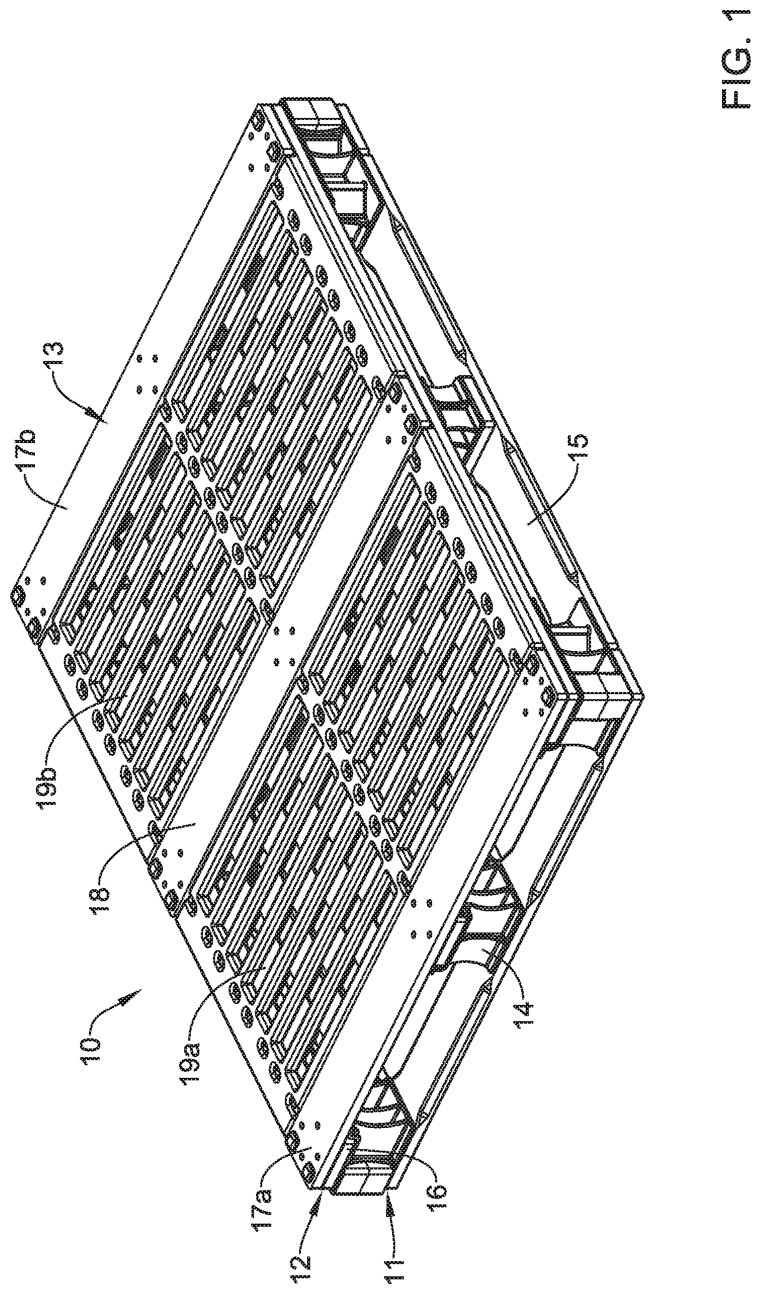
FIGS. 1-3 are perspective views of an example composite pallet 10. The composite pallet 10, as the name suggests, is at least partially formed from composite materials. In at least some instances, the composite pallet 10 includes one or more components that include a polymeric material (e.g., polypropylene, high density polyethylene, nylon, combinations thereof, and the like, or other materials disclosed herein). One or more of the polymeric materials/components may include a fiber reinforcement and/or other structural reinforcement. Some additional details regarding the components of the pallet 10 are disclosed herein.
The shape and configuration of the pallet 10 may vary. In some instances, the pallet 10 may have a generally polygonal shape. Because the pallet 10 may have a height, width, and depth, the pallet may be understood as a three-dimensional polygonal shape. In some instances, the shape of the pallet 10 may be described a rectangular prism. A number of additional shapes are contemplated. For convenience, the shape of the pallet 10 may be described in terms of the shape of the pallet 10 in two dimensions when viewing its top surface. For example, when viewing the top surface, the pallet 10 may have a shape that resembles a regular polygon or irregular polygon. In some of these and in other instances, the pallet 10 may have a rounded shape, an irregular shape, or the like. In some instances, the pallet 10 may be viewed as having 3 sides, 4 sides (e.g., a square, a rectangle, a parallelogram, etc.), 5 sides, 6 sides, 7 sides, 8 sides, or more. Some or all of the sides may be the same length. Alternatively, the sides may differ in length. The corners may be squared, rounded, or have another suitable shape. In one example, the pallet 10 may have a rectangular shape (e.g., when looking at the top surface) and may measure about 48 inches (1.2 m).times.40 inches (1.0 m). Other sizes, shapes, and configurations are contemplated.
The pallet 10 may include a base or base layer 11, an intermediate layer 12, and a top layer 13. The base layer 11 may include a plurality of base boards 15 and the base layer 11 may be coupled to the intermediate layer 12 by a plurality of support blocks 14. The intermediate layer 12 may include a plurality of intermediate boards 16. The top layer 13 may include a plurality of end boards including a first end board 17a and a second end board 17b. The top layer 13 may also include a structural board 18. The structural board 18 may be the same or different from other boards of the top layer 13 (e.g., such as the first end board 17a and/or the second end board 17b). The top layer 13 may also include a number of panels including a first panel 19a and a second panel 19b. Some additional description of the base layer 11, the intermediate layer 12, and the top layer 13 are described herein. Pallets are contemplated that utilize more or few layers.
The arrangement of the base layer 11, intermediate layer 12 and the support blocks 14 may allow a number of openings to be defined between the base layer 11 and the intermediate layer 12. For example, FIG. 2 illustrates that openings 20a, 20b, 20c, 20d may be defined between the base layer 11 and the intermediate layer 12. The openings 20a, 20b, 20c, 20d may allow a lifting device (e.g., tines of a mechanically assisted lifting device, such as a forklift, hand jack, walkie, or the like) to access the pallet 10 such that the pallet 10 may be lifted and moved. In some instances, the pallet 10 may define openings on each of the four side surfaces and, as such, the pallet 10 may be described as providing four-way entry because the lifting device may access the pallet 10 from each of those four side surfaces.
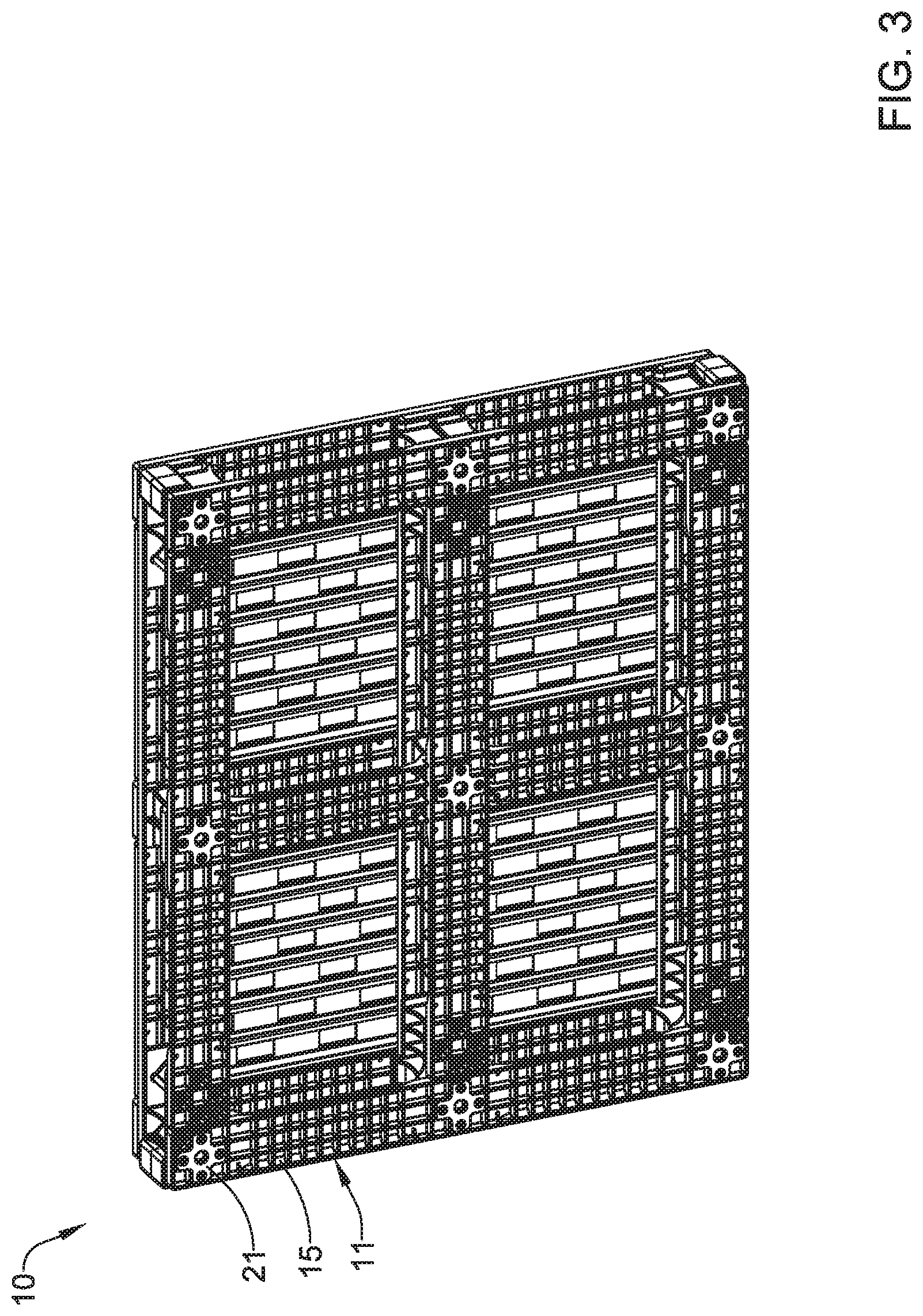
One or more wear pads 21 may be coupled to the base layer 11 as shown in FIG. 3. For example, one or more wear pads 21 may be attached to one or more of the base boards 15. The wear pads 21 may function as structures that allow the pallet 10 to be more easily moved, allow the pallet 10 to be less easily moved or otherwise resist motion, and/or allow the pallet 10 to have enhanced durability. For example, the wear pads 21 may include a friction-reducing surface or coating that provides a level of slipperiness that allows the pallet 10 to be more easily moved across a surface. The friction-reducing may take the form of a lubricous coating. Alternatively, the wear pads 21 may include a friction-increasing surface or coating that helps to reduce the pallet 10 moving or slipping across a surface. The friction-increasing surface may take the form of a tacky or sticky surface coating, a texturing, or the like. In at least some instances, the wear pads 21 are formed from or otherwise include a durable material (e.g. such as a durable polymer, metal, ceramic, carbon fiber, combinations thereof, or the like) designed to withstand wear. In addition, the wear pads 21 may be attached to the base boards 15 using a suitable fastener (e.g., a screw, nail, bolt, or the like) and may be easily replaced if desired.
FIG. 4 is perspective view of one of the base boards 15. Here it can be seen that the base board 15 includes a first end region 22a, a second end region 22b, and a central region 22c. A first region 24a may extend between the first end region 22a and the central region 22c. A second region 24b may extend between the second end region 22b and the central region 22c. The first region 24a, the second region 24b, or both may include one or more ramped surfaces or bevels 25. The bevels 25 may allow a device such as a forklift, a mechanical assist device such as a "walkie", or the like to more easily roll over the base boards 15 (e.g., and into one or more of the openings 20a, 20b, 20c, 20d). In at least some instances, the first end region 22a, the second end region 22b, the central region 22c, the first region 24a, the second region 24b, or combinations thereof may include one or more openings or apertures 23. The apertures 23 may be used to secure the base boards 15 to other structures of the pallet 10 using a suitable fastener (e.g., a screw, bolt, nail, or the like). In some instances, the apertures 23 are positioned along the first end region 22a, the second end region 22b, and the central region 22c. In some of these and in other instances, the first region 24a and the second region 24b are free of apertures 23. Other instances are contemplated, however, where the first region 24a and/or the second region 24b (and/or other portions of the base board 15) may include apertures 23.
The underside or bottom of the base boards 15 may include a number of structural features. For example, as shown in FIG. 5, the base board 15 may include a number of longitudinal ribs 26. The longitudinal ribs 26 may provide structural support to the base board 15. A suitable number of longitudinal ribs 26 may be disposed along the base board 15. For example, the base board 15 may include one, two, three, four, five, six, seven, eight, or more longitudinal ribs 26. The longitudinal ribs 26 may be equally spaced from one another. Alternatively, the distance between one or more of the longitudinal ribs 26 may vary along the base board 15. In some instances, all of the longitudinal ribs 26 extend along the full length of the base board 15. In other instances, one or more of the longitudinal ribs 26 extend along only a portion of the length of the base board 15. The height (e.g., which may be understood as the distance from the bottom surface of the base board 15 to the bottom surface of the longitudinal ribs 26) of the longitudinal ribs 26 may be substantially constant along the length of the longitudinal ribs 26 or may vary. For example, longitudinal ribs 26 are contemplated where the height varies in a wave-like pattern. In general, the longitudinal ribs 26 extend along a path that is aligned with or parallel to the longitudinal axis of the base board 15. However, even though the longitudinal ribs 26 are named "longitudinal", this is not intended to limit the longitudinal ribs 26 to being only oriented in a straight line along the longitudinal axis of the base board 15. Longitudinal ribs 26 are contemplated that extend diagonally, include curves or bends, or otherwise extend in directions other than just along the longitudinal axis.
In at least some instances, the longitudinal ribs 26 may be arranged in a relatively dense pattern. For example, the space between adjacent longitudinal ribs 26 may be about 0.25-2 inches, or about 0.5-1.5 inches, or about 1 inch. By having the longitudinal ribs 26 arranged in a relatively dense pattern, the longitudinal ribs 26 can provide a greater amount of structural support to the base board 15. In some instances, all of the longitudinal ribs 26 may have the same thickness or width. In other instances, one or more of the longitudinal ribs 26 may have a different (e.g., increased) width or thickness. For example, the longitudinal ribs 26 nearest the periphery of the base board 15 may have an increased width or thickness relative to other longitudinal ribs 26. The same may be true of other components of the pallet 10 and/or the components of other pallets disclosed herein.
The base board 15 may include a number of transverse ribs 27. A suitable number of transverse ribs 27 may be disposed along the base board 15. For example, the base board 15 may include 1-100, or more, transverse ribs 27. The transverse ribs 27 may be equally spaced from one another. Alternatively, the distance between two or more of the transverse ribs 27 may vary along the base board 15. In some instances, all of the transverse ribs 27 extend along the full width of the base board 15. In other instances, one or more of the transverse ribs 27 extend along only a portion of the width of the base board 15. Indeed, a single transverse rib 27 may be considered to be a structure that extends between two adjacent longitudinal ribs 26. The height (e.g., which may be understood as the distance from the bottom surface of the base board 15 to the bottom surface of the transverse ribs 27) of the transverse ribs 27 may be substantially constant along the length of the transverse ribs 27 or may vary. For example, transverse ribs 27 are contemplated where the height varies in a wave-like pattern. In general, the transverse ribs 27 extend along a path that is transverse or perpendicular to the longitudinal axis of the base board 15. However, even though the transverse ribs 27 are named "transverse", this is not intended to limit the transverse ribs 27 to being only oriented in a straight line transverse to the longitudinal axis of the base board 15. Transverse ribs 27 are contemplated that extend diagonally, include curves or bends, or otherwise extend in directions other than just transverse to the longitudinal axis.
The transverse ribs 27 may be disposed along essentially the entire length of the base board 15. Alternatively, the transverse ribs 27 may be disposed along one or more portions of the base board 15. For example, in the base board 15 depicted in FIG. 5, the transverse ribs 27 are shown disposed along the first region 24a and the second region 24b. In other words, the parts of the base board 15 where a mechanical assist device (e.g., a forklift, walkie, etc.) is more likely to pass over during use of the pallet 10 may have transverse ribs 27. This allows the transverse ribs 27 to provide structural support to the base board 15 along the first region 24a and the second region 24b where structural support may be desired while also allowing other portions of the base board 15 (e.g., those portions lacking transverse ribs 27) to have less material/weight. In this example, the central region 22c is at least partially free of transverse ribs 27. Other arrangements are contemplated. In some instances, the base board 15 may include one or more gussets 28. The gussets 28 may be disposed along the central region 22c (and/or other portions of the base board 15).
A cross-sectional view of the base board 15 is shown in FIG. 6. Here some of the other structural features of the base board 15 can be seen. For example, one or more of the longitudinal ribs 26 may include a tension member 29. In some instances, the tension member 29 may be described as a continuous fiber bundle that includes a plurality of fibers or filaments in a thermoplastic resin (e.g., which may resemble the fiber bundles described below with respect to the structural member 30). The tension member 29 may provide strength in tension to increase the overall strength of the base board 15, for example, by preventing the base board 15 from bowing or cracking or breaking when a force is applied thereto. The tension member 29 may include a range of thickness/filament counts. For example, the tension member 29 may define a thickness (e.g., a diameter) of about greater than or equal to 0.05 inches, greater than or equal to 0.1 inches, greater than or equal to 0.125 inches, etc. and/or less than or equal to 0.25 inches, less than or equal to 0.2 inches, less than or equal to 0.15 inches, etc. Also, for example, the tension member 29 may include at least between 1,000 and 20,000 continuous fibers dispersed in a thermoplastic material. In one or more embodiments, the tension member 29 may be twisted to further increase the tensile strength. For example, the tension member 29 may be grouped in portions of 4,000 continuous fibers that are twisted and combined with additional groups of continuous fibers that may be twisted. The tension member 29 (and/or a continuous fiber bundle) may be as described in U.S. patent application Ser. No. 14/621,188, filed on Feb. 12, 2015, and entitled, "COMPOSITE STRUCTURAL ARTICLE," and International Patent Application No. PCT/US16/17519, filed on Feb. 11, 2016, and entitled, "PRE-STRESSED FIBER REINFORCING MEMBER," and International Application No. PCT/US2015/044789, filed on Aug. 12, 2015, and entitled, "REINFORCING ARTICLE," which are both hereby incorporated herein by reference in their entirety to the extent that it does not conflict with the present disclosure.
The base board 15 may include a suitable number of tension members 29. For example, the base board 15 may include a tension member 29 in each of the longitudinal ribs 26. In at least some instances, the tension members 29 are positioned near an end or edge region of the longitudinal ribs 26. Other positions along the longitudinal ribs 26 may include tension members 29. In other instances, some or all of the longitudinal ribs 26 may lack tension members 29 and/or tension members 29 are disposed along other portions of the base board 15. Some base boards 15 are contemplated that do not have a tension member 29 at all.
The base board 15 may also include a structural member 30. The structural member 30 may include a plurality of fibers 30a (e.g., which may include glass fibers, carbon fibers, basalt fibers, graphite fibers, aramid fibers, ceramic fibers, natural fibers, polymeric fibers, metal fibers, combinations thereof, or the like) and, in some cases, a carrier material or mesh 30b. In at least some instances, the fibers 30a take the form of a fiber bundle or tow (e.g., that may include 1000 or more fibers) that is formed by coating the individual fibers with a resin (e.g., wetting-out) and compounding the individual fibers (e.g., via a pultrusion process). The fiber bundles 30a may include fibers (e.g., individual fibers or filaments) that are combined and/or shaped in such a way so as to result in fiber bundles 30a having a variety of widths, thicknesses, heights, diameters, etc. The arrangement of the fibers 30a (and/or fiber bundles 30a) can vary. For example, the fiber bundles 30a may be disposed along or otherwise parallel with the longitudinal axis of the base board 15. Alternatively, the fiber bundles 30a may be oriented at an angle of 0-90 degrees (+/-45 degrees) relative to the longitudinal axis of the base board 15. In some instances, the fiber bundles 30a are spaced from one another. In other instances the fiber bundles 30a may intersect or cross. The structural member 30 may be disposed at a suitable location along or within the base board 15. In at least some instances, the structural member 30 is disposed adjacent to the bottom of the base board 15. Other locations are contemplated.
As indicated above, the fiber bundles 30a may include individual fibers that may be coated with and/or otherwise penetrated by a resin. In some instances, the resin coating the fibers may be understood to be "compatible" with the resin/material(s) used to form the base board 15. In at least some instances, the resin coating the fibers may be considered compatible with the resin/materials(s) of the base board 15 when the resin coating the fibers is the same as (or similar to and/or bond compatible with) the resin/materials(s) of the base board 15. For example, if the base board 15 includes polypropylene, when the resin coating the fibers is also polypropylene, the resin is considered to be compatible. The use of "compatible" resins may allow the structural member 30 to bond or otherwise be molded with the base board 15 more completely or otherwise in a manner that allows the structural member 30 to provide structural support to the base board 15.
In some instances, the resin coating the fibers may be understood to be "non-compatible" or "less compatible" with the resin/material(s) used to form the base board 15. In at least some instances, the resin coating the fibers may be considered non-compatible with the resin/materials(s) of the base board 15 when the resin coating the fibers is different from the resin/materials(s) of the base board 15. For example, if the base board 15 includes polypropylene, when the resin coating the fibers is something other than polypropylene (e.g., such as any of the other materials disclosed herein), the resin may be considered to be non-compatible. The use of "non-compatible" resins may allow the structural member 30 to bond or otherwise be molded with the base board 15 in a manner that the structural member 30 that provides enhanced impact resistance (e.g., due to, for example, a less complete bond that allows the impact member 30 to "give" or cushion impact thereon). Thus, some "structural" members 30 are contemplated that utilize fibers encased in or otherwise penetrated by a non-compatible resin and such "structural" members 30 may be considered to be "impact" members 30 or "impact resistance" members 30. It is noted that the same reference number (reference number 30) is utilized in FIG. 6 to refer to a structure that can be described as either (a) a structural member 30 that provides structural support or (b) a structure, different from the structural member that provides structural support, that can be described as an impact member 30.
Collectively, some structural members 30 are contemplated that utilize the same resins for the fiber bundles 30a and for the base boards 15, and such structural members 30 may be considered to provide structural support and thus be considered structural members 30. Other structural members 30 are contemplated that utilize different resins for the fiber bundles 30a and the base boards 15, and such structural members 30 may be considered to provide impact resistance and thus be considered impact members 30. Some pallets 10 are contemplated that include both structural members 30 and impact members 30. Finally, the magnitude of the compatibility of the resin for use with the fiber bundles 30a can vary along a continuum, depending on the materials utilized. For example, some resin combinations may have a partial level of compatibility. Thus, structural members 30 are contemplated where the resins used with the fiber bundles 30a are partially compatible with the resins of the base board 15. Such structural members 30 may be understood as both a structural member (providing structural support) and an impact member (providing impact resistance). Accordingly, pallets 10 are contemplated that include structural members 30, impact members 30, a structural member 30 that is considered to be both a structural member and an impact member, or combinations thereof.
The base boards 15 may be formed from a suitable material. For example, the base boards 15 may be made from polypropylene, high density polyethylene, nylon, combinations thereof, and the like, or other materials disclosed herein. In addition to the tension members 29 and structural members 30 described above, the base boards 15 may include additional reinforcement such as fiber reinforcements (e.g., reinforcement with glass fibers, carbon fibers, basalt fibers, graphite fibers, aramid fibers, ceramic fibers, natural fibers, polymeric fibers, metal fibers, combinations thereof, or the like). In some instances, all of the base boards 15 are the same. In other instances, one or more of the base boards 15 may differ in structure. Some of the differences contemplated include differences where one or more of the base boards 15 include structures found in some of the other components of the pallet 10.
The base boards 15 may be formed using a suitable process such as compression molding, transfer molding, injection molding, base molding, casting, or the like. In some instances, a mold 78 (a portion of which is shown in FIG. 6A, may be utilized). The mold 78 may have a textured surface 79 including one or more grooves 80 that are cut into the mold 78. Between the grooves 80 or otherwise along portions of the mold 78 where the grooves 80 are not formed, portions 81 of the mold 78 remain that appear raised in FIG. 6A. When a material is disposed in the mold 78, for example to form the base board 15, the textured surface 79 in the mold 78 may result in a corresponding textured surface 76 along a portion of the base board 15 (e.g., a bottom surface) as shown in FIG. 6B (and also depicted in FIG. 6). In this example, the textured surface 76 may include one or more ridges or bumps 82. The textured surface 76 may be desirable for a number of reasons. For example, the textured surface 79 of the mold 78 may allow material to flow underneath a structural member 30 placed in the mold 78 as part of the molding process. Because of this, the material flowing underneath the structural member 30 may encapsulate at least a portion of (and in some cases all of) the structural member 30. This may improve the bond between the structural member 30 and the base board 15. For example, the mechanical and/or chemical bond between the structural member 30 and the base board 15 may be enhanced by the textured surface 79 of the mold 78.
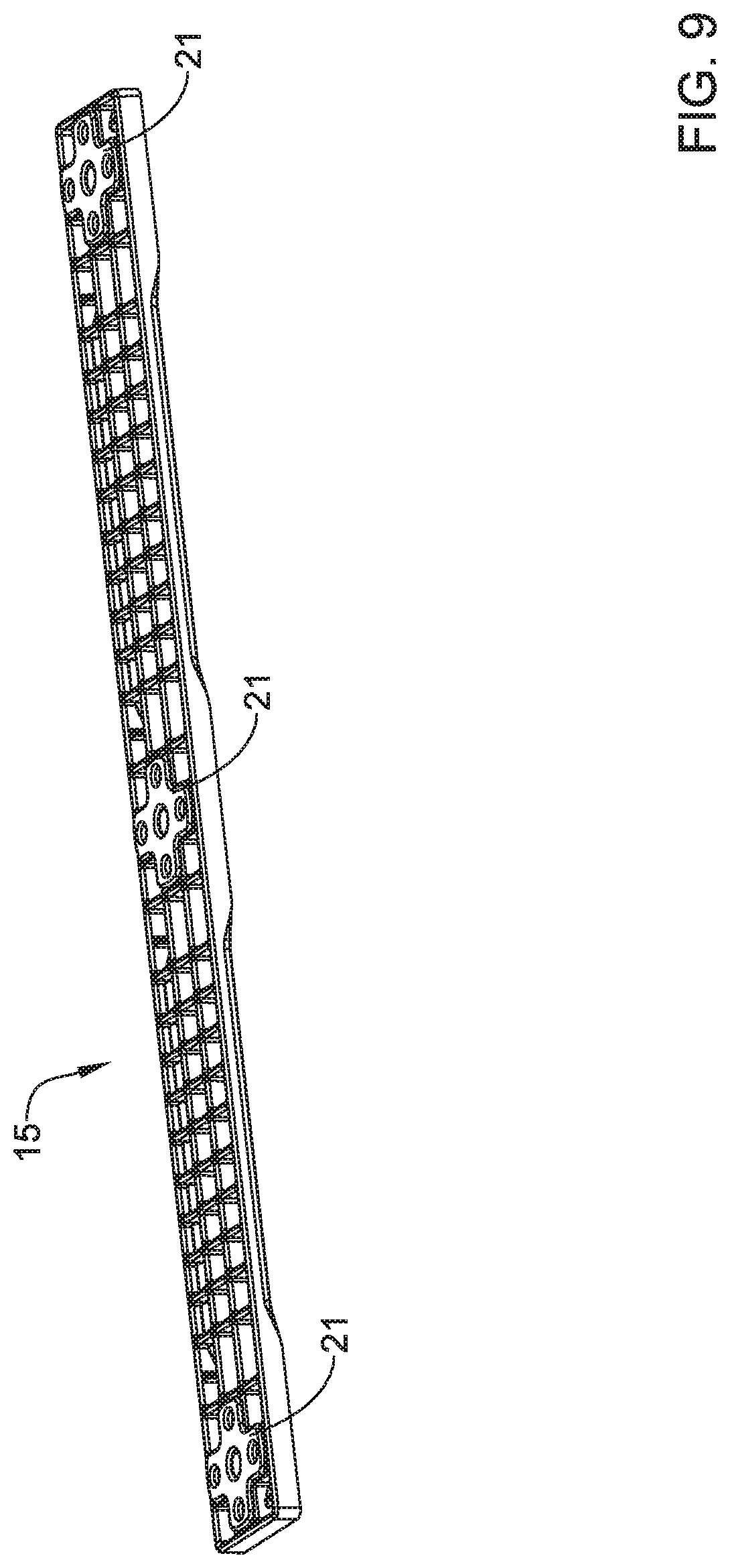
FIGS. 7-8 illustrate the wear pads 21. The wear pads 21 may include a first or "bottom" surface 31a (e.g., as shown in FIG. 7) and a second or "top" surface 31b (e.g., as shown in FIG. 8). A plurality of openings 32 may be formed in wear pads 21. The openings 32 may be used to secure the wear pads 21 to the base boards 15 as depicted in FIG. 9. For example, a suitable fastener (e.g., such as a screw, nail, bolt, or the like) may be used to secure the wear pads 21 to the base boards 15. If a particular type of wear pad 21 is desired, the pallet 10 can be modified to replace a first type of wear pad 21 (e.g., a "slippery" wear pad 21) with a second type of wear pad 21 (e.g., a 22121 with a high friction surface).
FIG. 10 illustrates an example configuration of the base boards 15 in the base layer 11. Here it can be seen that the base layer 11 may include a plurality of base boards 15 including the base boards 15a, 15b, 15c, 15d, and 15e shown in FIG. 10. The number and arrangement of the base boards 15a, 15b, 15c, 15d, and 15e can vary. For example, some base layers 11 are contemplated that include five base boards 15a, 15b, 15c, 15d, and 15e as shown, whereas other base layers 11 may include more or fewer base boards 15. In some instances, all of the base boards 15a, 15b, 15c, 15d, and 15e are the same. In other instances, one or more of the base boards 15a, 15b, 15c, 15d, and 15e have a differing shape, size, structural configuration, material composition, or the like.
FIGS. 11-12 illustrate an example cross-member 33. Here it can be seen that the cross-member 33 may include a first end region 34a, a second end region 34b, and a central region 34c. A first region 35a may be disposed between the first end region 34a and the central region 34c. A second region 35b may be disposed between the second end region 34b and the central region 34c. The first region 35a, the second region 35b, or both may include one or more ramped surfaces or bevels 36.
The first end region 34a, the second end region 34b, and the central region 34c are substantially coplanar and lie within a first plane. The first region 35a and the second region 35b may be coplanar and lie within a second plane. In at least some instances, the first plane and the second plane are spaced from one another and, for example, may be substantially parallel with one another. The cross-member 33 may include one or more curved regions that form transitions between the first plane and the second plane. For example, the cross-member 33 may include a first curved region 37a, a second curved region 37b, a third curved region 37c, and a fourth curved region 37d. The first curved region 37a may be disposed between the first end region 34a and the first region 35a. The second curved region 37b may be disposed between the first region 35a and the central region 34c. The third curved region 37c may be disposed between the central region 34c and the second region 35b. The fourth curved region 37d may be disposed between the second region 35b and the second end region 34b. The curving of the curved regions 37a, 37b, 37c, and 37d may have a suitable radius of curvature. The radius of curvature may be constant or may vary along each of the curved regions 37a, 37b, 37c, and 37d (and/or may vary amongst different curved regions 37a, 37b, 37c, and 37d).
The cross-member 33 may include a number of longitudinal ribs 38. The longitudinal ribs 38 may provide structural support to the cross-member 33. A suitable number of longitudinal ribs 38 may be disposed along the cross-member 33. For example, the cross-member 33 may include one, two, three, four, five, six, seven, eight, or more longitudinal ribs 38. The longitudinal ribs 38 may be equally spaced from one another. Alternatively, the distance between one or more of the longitudinal ribs 38 may vary along the cross-member 33. In some instances, all of the longitudinal ribs 38 extend along the full length of the cross-member 33. In other instances, one or more of the longitudinal ribs 38 extend along only a portion of the length of the cross-member 33. The height (e.g., which may be understood as the distance from the bottom surface of the cross-member 33 to the bottom surface of the longitudinal ribs 38) of the longitudinal ribs 38 may be substantially constant along the length of the longitudinal ribs 38 or may vary. For example, longitudinal ribs 38 are contemplated where the height varies in a wave-like pattern. In general, the longitudinal ribs 38 extend along a path that is aligned with or parallel to the longitudinal axis of the cross-member 33. However, even though the longitudinal ribs 38 are named "longitudinal", this is not intended to limit the longitudinal ribs 38 to being only oriented in a straight line along the longitudinal axis of the cross-member 33. Longitudinal ribs 38 are contemplated that extend diagonally, include curves or bends, or otherwise extend in directions other than just along the longitudinal axis.
In at least some instances, the longitudinal ribs 38 may be arranged in a relatively dense pattern. For example, the space between adjacent longitudinal ribs 38 may be about 0.25-2 inches, or about 0.5-1.5 inches, or about 1 inch. By having the longitudinal ribs 38 arranged in a relatively dense pattern, the longitudinal ribs 38 can provide a greater amount of structural support to the cross-member 33. In some instances, all of the longitudinal ribs 38 may have the same thickness or width. In other instances, one or more of the longitudinal ribs 38 may have a different (e.g., increased) width or thickness. For example, the longitudinal ribs 38 nearest the periphery of the cross-member 33 may have an increased width or thickness relative to other longitudinal ribs 38. The same may be true of other components of the pallet 10 and/or the components of other pallets disclosed herein.
The cross-member 33 may include a number of transverse ribs 39. A suitable number of transverse ribs 39 may be disposed along the cross-member 33. For example, the cross-member 33 may include 1-100, or more, transverse ribs 39. The transverse ribs 39 may be equally spaced from one another. Alternatively, the distance between two or more of the transverse ribs 39 may vary along the cross-member 33. In some instances, all of the transverse ribs 39 extend along the full width of the cross-member 33. In other instances, one or more of the transverse ribs 39 extend along only a portion of the width of the cross-member 33. Indeed, a single transverse rib 39 may be considered to be a structure that extends between two adjacent longitudinal ribs 38. The height (e.g., which may be understood as the distance from the bottom surface of the cross-member 33 to the bottom surface of the transverse ribs 39) of the transverse ribs 39 may be substantially constant along the length of the transverse ribs 39 or may vary. For example, transverse ribs 39 are contemplated where the height varies in a wave-like pattern. In general, the transverse ribs 39 extend along a path that is transverse or perpendicular to the longitudinal axis of the cross-member 33. However, even though the transverse ribs 39 are named "transverse", this is not intended to limit the transverse ribs 39 to being only oriented in a straight line transverse to the longitudinal axis of the cross-member 33. Transverse ribs 39 are contemplated that extend diagonally, include curves or bends, or otherwise extend in directions other than just transverse to the longitudinal axis. In some instances, the intersections of the longitudinal ribs 38 and the transverse ribs 39 may define sockets or compartments into which other structures of the pallet 10 may extend. This may help to secure or interlock various structures of the pallet 10. In some instances, the cross-member 33 may include one or more gussets 77.
A cross-sectional view of the cross-member 33 is shown in FIG. 13. Here some of the other structural features of the cross-member 33 can be seen. For example, one or more of the longitudinal ribs 38 may include a tension member 29 (e.g., that may be similar in form and function to the tension member 29 described above with respect to the base board 15). The cross-member 33 may also include a structural member 30 (e.g., that may be similar in form and function to the structural member 30 described above with respect to the base board 15). As described above in relation to the base board 15, the "structural" member 30 may take the form of a structural member 30, an impact member 30, a member 30 that provides both structural support and impact resistance, or combinations thereof. The cross-member 33 may also have a textured bottom surface 76, similar to that of the base board 15.
FIG. 14 illustrates the base layer 11. Here it can be seen that the base layer 11 may include a plurality of base boards 15 including the base boards 15a, 15b, 15c, 15d, and 15e. The base layer 11 may also include the cross-member 33. As shown in FIG. 14, the base boards 15a, 15b, 15c, 15d, and 15e may be coplanar with the first region 35a and the second region 35b. The first end region 34a, the second end region 34b, and the central region 34c may lie in a plane that is spaced from and substantially parallel to the plane in which the base boards 15a, 15b, 15c, 15d, and 15e as well as the first region 35a and the second region 35b of the cross-member 33 lie.
As indicated herein, the composite pallet 10 may include a plurality of support blocks 14. In some instances, different types of support blocks 14 may be utilized. FIGS. 15-16 illustrate a first support block 14a. The first support block 14a may include a top surface 40a and a bottom surface 40b. A number of openings 45 may be formed in the first support block 14a. In at least some instance, fasteners (e.g., screws, nails, bolts, or the like) may be extended through the openings to secure the first support block 14a to other components of the pallet 10. The first support block 14a may also include one or more projections 83. The projections 83 are designed so that the first support block 14a can fit within and/or interlock with a corresponding socket formed along a bottom surface of a board (e.g., an intermediate board 16) that is disposed along the top surface 40a. The shape and/or configuration of the projections 83 can vary. For example, the projections 83 may have a "X" shape, as shown. Other shapes are contemplated including squared shapes (e.g., cubic, rectangular prism, or the like), rounded shapes (spherical, cylindrical, conical, or the like), irregular shapes, or the like. In some instances, the shape of the socket is designed to key with or mate with the projections 83. In other instances, the shape of the socket may differ from that of projections 83 (e.g., the sockets have a squared shape defined by the intersection of longitudinal and transverse ribs but still allow the projections 83 to fit therein).
In at least some instance, the first support block 14a is a solid (e.g., non-hollow) structure. A plurality of ribs 41 may be disposed between the top surface 40a and the bottom surface 40b. The ribs 41 may allow the first support block 14a to provide structural support (e.g., to the intermediate boards 16) while taking up less space and while having a reduced weight. The ribs 41 can have a variety of arrangements and/or configurations. The first support block 14a may also include a lip or flanged region 42. The lip 42 may be designed to be positioned along an inside surface of an intermediate board 16 and provide support thereto.
In addition to what is described above, the shape, configuration and/or arrangement of the first support block 14a can vary. For example, the first support block 14a may include a cutout region 43 and a platform region 44. The cutout region 43 and the platform region may be used to house a push support member (not shown in FIGS. 15-16, but an example push support member 47 can be seen, for example, in FIGS. 17-19). A cutout region 46 may be formed along the bottom surface 40b.
FIGS. 17-18 illustrate an example push support member 47. The push support member 47 may include a first or "top" surface 48a and a second or "bottom" surface 48b. A boss or projection 49 may extend from the top surface 48a. An opening 50 may be formed in the bottom surface 48b. The push support member 47 may include a bumper or push surface 51. The push surface 51 (and/or the complete push support members 47) may be formed from a ductile, soft, rubbery, and/or impact absorbing material. Some example materials may include rubber, a thermoplastic elastomer, other elastomers, or the like.
FIG. 19 illustrates the push support member 47 coupled to the first support block 14a. When doing so, the push support member 47 may be disposed adjacent to the cutout region 43 and positioned along the platform region 44. The push support members 47 may be secured to the first support block 14a using a suitable fastener such as a screw, nail, bolt, or the like.
FIGS. 20-25 illustrate additional support blocks that may have some similarity to the first support block 14a. For example, FIGS. 20-21 illustrates a second support block 14b similar in form and function to other support blocks disclosed herein. Like the first support block 14a, the second support block 14b may include a top surface 40a, a bottom surface 40b, ribs 41, a lip 42, a cutout region 43, a platform region 44, openings 45, and projections 83. FIG. 22-23 illustrate a third support block 14c similar in form and function to other support blocks disclosed herein. The third support block 14c may include a top surface 40a, a bottom surface 40b, ribs 41, a pair of flanges 42a, 42b along the top surface 40a, openings 45, projections 83, and a pair of cutouts 46a, 46b along the bottom surface 40b. FIGS. 24-25 illustrate a fourth support block 14d. The fourth support block 14d may include a top surface 40a, a bottom surface 40b, ribs 41, openings 45, and projections 83.
FIG. 26 illustrates a sub assembly of the base layer 11 along with the support blocks 14a, 14b, 14c, and 14d. Here, one example arrangement of the support blocks 14a, 14b, 14c, and 14d can be seen. For example, the first support blocks 14a may be positioned at opposite corners of the base layer 11. These support blocks 14a may be considered to be "left-hand corner" support blocks 14a. Similarly, the second support blocks 14b may be positioned at opposite corners of the base layer 11. These support blocks 14b may be considered to be "right-hand corner" support blocks 14a. Two of the third support blocks 14c may be positioned along the middle portion of the base boards 15a, 15b. In at least some instances, three support blocks 14d are disposed along the cross-member 33. At these positions, the base layer 11 includes both a base board (e.g., a base board 15c, 15d, or 15e) and the cross-member 33. Because of the thickness of the base board 15c, 15d, 15e in combination with the thickness of the cross-member 33, the support blocks 14d may have a reduced height when compared with the remaining support blocks 14a, 14b, and 14c so that, for example, the top surfaces of the support blocks 14a, 14b, 14c, and 14d are arranged at the same position or height.
In addition, the push support members 47 are shown disposed along the corners of both the first support blocks 14a and the second support blocks 14b. While this is one arrangement, other arrangements are contemplated. For example, more or fewer push support members 47 may be utilized. The push support members 47 may be disposed at different positions/sides of the first support blocks 14a and/or the second support blocks 14b. In addition, the other support blocks 14c, 14d may also include push support members 47, as desired.
FIGS. 27-28 illustrate an example intermediate board 16. The intermediate board 16 may include a first end region 53a, a second end region 53b, and a central region 53c. A first section 54a may be disposed between the first end region 53a and the central region 53c. A second section 54b may be disposed between the second end region 53b and the central region 53c. A plurality of apertures 55 may be disposed along the intermediate board 16.
The first section 54a, the second section 54b, or both may include one or more top surface ribs 56. The top surface ribs 56 may provide additional structural support, aid in assembly, and/or the like. One or more bosses 57 may be disposed along the first section 54, the second section 54b, or both. At least some of the bosses 57 may have apertures 55 formed therein. The apertures 55 may be designed to be used with a suitable fastener (e.g., a screw, nail, bolt, or the like) to secure the intermediate board 16 to other structures of the pallet 10. The bosses 57 may be designed to interlock with another structure such as a top board 17 disposed thereon.
The underside or bottom of the intermediate board 16 may include a number of structural features. For example, as shown in FIG. 28, the intermediate board 16 may include a number of longitudinal ribs 58. The longitudinal ribs 58 may provide structural support to the intermediate board 16. A suitable number of longitudinal ribs 58 may be disposed along the intermediate board 16. For example, the intermediate board 16 may include one, two, three, four, five, six, seven, eight, or more longitudinal ribs 58. The longitudinal ribs 58 may be equally spaced from one another. Alternatively, the distance between one or more of the longitudinal ribs 58 may vary along the intermediate board 16. In some instances, all of the longitudinal ribs 58 extend along the full length of the intermediate board 16. In other instances, one or more of the longitudinal ribs 58 extend along only a portion of the length of the intermediate board 16. The height (e.g., which may be understood as the distance from the bottom surface of the intermediate board 16 to the bottom surface of the longitudinal ribs 58) of the longitudinal ribs 58 may be substantially constant along the length of the longitudinal ribs 58 or may vary. For example, longitudinal ribs 58 are contemplated where the height varies in a wave-like pattern. In general, the longitudinal ribs 58 extend along a path that is aligned with or parallel to the longitudinal axis of the intermediate board 16. However, even though the longitudinal ribs 58 are named "longitudinal", this is not intended to limit the longitudinal ribs 58 to being only oriented in a straight line along the longitudinal axis of the intermediate board 16. Longitudinal ribs 58 are contemplated that extend diagonally, include curves or bends, or otherwise extend in directions other than just along the longitudinal axis.
In at least some instances, the longitudinal ribs 58 may be arranged in a relatively dense pattern. For example, the space between adjacent longitudinal ribs 58 may be about 0.25-2 inches, or about 0.5-1.5 inches, or about 1 inch. By having the longitudinal ribs 26 arranged in a relatively dense pattern, the longitudinal ribs 58 can provide a greater amount of structural support to the intermediate board 16. In some instances, all of the longitudinal ribs 58 may have the same thickness or width. In other instances, one or more of the longitudinal ribs 58 may have a different (e.g., increased) width or thickness. For example, the longitudinal ribs 58 nearest the periphery of the intermediate board 16 may have an increased width or thickness relative to other longitudinal ribs 58.
The intermediate board 16 may include a number of transverse ribs 59. A suitable number of transverse ribs 59 may be disposed along the intermediate board 16. For example, the intermediate board 16 may include 1-100, or more, transverse ribs 59. The transverse ribs 59 may be equally spaced from one another. Alternatively, the distance between two or more of the transverse ribs 59 may vary along the intermediate board 16. In some instances, all of the transverse ribs 59 extend along the full width of the intermediate board 16. In other instances, one or more of the transverse ribs 59 extend along only a portion of the width of the intermediate board 16. Indeed, a single transverse rib 59 may be considered to be a structure that extends between two adjacent longitudinal ribs 58. The height (e.g., which may be understood as the distance from the bottom surface of the intermediate board 16 to the bottom surface of the transverse ribs 59) of the transverse ribs 59 may be substantially constant along the length of the transverse ribs 59 or may vary. For example, transverse ribs 59 are contemplated where the height varies in a wave-like pattern. In general, the transverse ribs 59 extend along a path that is transverse or perpendicular to the longitudinal axis of the intermediate board 16. However, even though the transverse ribs 59 are named "transverse", this is not intended to limit the transverse ribs 59 to being only oriented in a straight line transverse to the longitudinal axis of the intermediate board 16. Transverse ribs 59 are contemplated that extend diagonally, include curves or bends, or otherwise extend in directions other than just transverse to the longitudinal axis. In some instances, the intersections of the longitudinal ribs 58 and the transverse ribs 59 may define sockets or compartments into which other structures of the pallet 10 may extend. This may help to secure or interlock various structures of the pallet 10.
A cross-sectional view of the intermediate board 16 is shown in FIG. 29. Here some of the other structural features of the intermediate board 16 can be seen. For example, one or more of the longitudinal ribs 58 may include a tension member 29. In some instances, the tension member 29 may be described as a continuous fiber bundle that includes a plurality of fibers in a thermoplastic resin. The tension member 29 may provide strength in tension to increase the overall strength of the intermediate board 16, for example, by preventing the intermediate board 16 from bowing or cracking or breaking when a force is applied thereto. The tension member 29 may include a range of thickness/filament counts. For example, the tension member 29 may define a thickness (e.g., a diameter) of about greater than or equal to 0.05 inches, greater than or equal to 0.1 inches, greater than or equal to 0.125 inches, etc. and/or less than or equal to 0.25 inches, less than or equal to 0.2 inches, less than or equal to 0.15 inches, etc. Also, for example, the tension member 29 may include at least between 1,000 and 20,000 continuous fibers dispersed in a thermoplastic material. In one or more embodiments, the tension member 29 may be twisted to further increase the tensile strength. For example, the tension member 29 may be grouped in portions of 4,000 continuous fibers that are twisted and combined with additional groups of continuous fibers that may be twisted.
The intermediate board 16 may include a suitable number of tension members 29. For example, the intermediate board 16 may include a tension member 29 in each of the longitudinal ribs 58. In at least some instances, the tension members 29 are positioned near an end or edge region of the longitudinal ribs 58. Other positions along the longitudinal ribs 58 may include tension members 29. In other instances, some or all of the longitudinal ribs 58 may lack tension members 29 and/or tension members 29 are disposed along other portions of the intermediate board 16. Some intermediate boards 16 are contemplated that do not have a tension member 29 at all.
The intermediate board 16 may also include a structural member 30. As described above in relation to the base board 15, the "structural" member 30 may take the form of a structural member 30, an impact member 30, a member 30 that provides both structural support and impact resistance, or combinations thereof. Some intermediate boards 16 are contemplated that do not have a structural member 30 at all. The intermediate board 16 may also have a textured bottom surface 76, similar to that of the base board 15.
The intermediate board 16 may be formed from a suitable material. For example, the intermediate board 16 may be made from polypropylene, high density polyethylene, nylon, combinations thereof, and the like, or other materials disclosed herein. In addition to the tension members 29 and structural members 30 described above, the intermediate board 16 may include additional reinforcement such as fiber reinforcements (e.g., reinforcement with glass fibers, carbon fibers, basalt fibers, graphite fibers, aramid fibers, ceramic fibers, natural fibers, polymeric fibers, metal fibers, combinations thereof, or the like). The intermediate board 16 may be formed using a suitable process such as injection molding, base molding, casting, or the like. In some instances, all of the intermediate boards 16 are the same. In other instances, one or more of the intermediate boards 16 may differ in structure. Some of the differences contemplated include differences where one or more of the intermediate boards 16 include structures found in some of the other components of the pallet 10.
FIG. 30 illustrates a subassembly of the pallet 10 where the intermediate boards 16 are coupled to the support blocks 14a, 14b, 14c, 14d. In this example, three intermediate boards 16a, 16b, 16c are utilized. However, more or fewer intermediate boards may be utilized. In at least some instances, the intermediate boards 16a, 16b, and 16c are arranged perpendicularly relative to the cross-member 33. However, other arrangements are contemplated.
FIGS. 31-32 illustrate an example top board 17. The top board 17 may include a first end region 63a, a second end region 63b, and a central region 63c. A first section 64a may be disposed between the first end region 63a and the central region 63c. A second section 64b may be disposed between the second end region 63b and the central region 63c. A plurality of apertures 65 may be disposed along the top board 17.
In at least some instances, the top board 17 may include one or more projections 66. The projections 66 may be attached to the top board 17 or may be integral parts of the top board 17 (e.g., the projections 66 are part of a common mold that is used to form the top board 17). The projections 66 may serve as stops or structural features that allow goods placed on the pallet 10 to engage so that the good can be substantially prevented from sliding off of the pallet 10. In addition, the projections 66 may aid in stacking a plurality of pallets 10 upon one another. For example, the projections 66 may interlock with grooves or sockets formed along the bottom surface of a base board 15 of an adjacent pallet 10. In some instances, the projections 66 are disposed along the first end region 63a, the second end region 63b, or both. However, this is not intended to be limiting. The projections 66 may be disposed along any suitable portion of the top board 17 such as along the central region 63c, the first section 64a, the second section 64b, and/or combinations thereof.
The underside or bottom of the top board 17 may include a number of structural features. For example, as shown in FIG. 32, the top board 17 may include a number of longitudinal ribs 67. The longitudinal ribs 67 may provide structural support to the top board 17. A suitable number of longitudinal ribs 67 may be disposed along the top board 17. For example, the top board 17 may include one, two, three, four, five, six, seven, eight, or more longitudinal ribs 67. The longitudinal ribs 67 may be equally spaced from one another. Alternatively, the distance between one or more of the longitudinal ribs 67 may vary along the top board 17. In some instances, all of the longitudinal ribs 67 extend along the full length of the top board 17. In other instances, one or more of the longitudinal ribs 67 extend along only a portion of the length of the top board 17. The height (e.g., which may be understood as the distance from the bottom surface of the top board 17 to the bottom surface of the longitudinal ribs 67) of the longitudinal ribs 67 may be substantially constant along the length of the longitudinal ribs 67 or may vary. For example, longitudinal ribs 67 are contemplated where the height varies in a wave-like pattern. In general, the longitudinal ribs 67 extend along a path that is aligned with or parallel to the longitudinal axis of the top board 17. However, even though the longitudinal ribs 67 are named "longitudinal", this is not intended to limit the longitudinal ribs 67 to being only oriented in a straight line along the longitudinal axis of the top board 17. Longitudinal ribs 67 are contemplated that extend diagonally, include curves or bends, or otherwise extend in directions other than just along the longitudinal axis.
In at least some instances, the longitudinal ribs 67 may be arranged in a relatively dense pattern. For example, the space between adjacent longitudinal ribs 67 may be about 0.25-2 inches, or about 0.5-1.5 inches, or about 1 inch. By having the longitudinal ribs 26 arranged in a relatively dense pattern, the longitudinal ribs 67 can provide a greater amount of structural support to the top board 17. In some instances, all of the longitudinal ribs 67 may have the same thickness or width. In other instances, one or more of the longitudinal ribs 67 may have a different (e.g., increased) width or thickness. For example, the longitudinal ribs 67 nearest the periphery of the top board 17 may have an increased width or thickness relative to other longitudinal ribs 67. The same may be true of other components of the pallet 10 and/or the components of other pallets disclosed herein.
The top board 17 may include a number of transverse ribs 68. A suitable number of transverse ribs 68 may be disposed along the top board 17. For example, the top board 17 may include 1-100, or more, transverse ribs 68. The transverse ribs 68 may be equally spaced from one another. Alternatively, the distance between two or more of the transverse ribs 68 may vary along the top board 17. In some instances, all of the transverse ribs 68 extend along the full width of the top board 17. In other instances, one or more of the transverse ribs 68 extend along only a portion of the width of the top board 17. Indeed, a single transverse rib 68 may be considered to be a structure that extends between two adjacent longitudinal ribs 67. The height (e.g., which may be understood as the distance from the bottom surface of the top board 17 to the bottom surface of the transverse ribs 68) of the transverse ribs 68 may be substantially constant along the length of the transverse ribs 68 or may vary. For example, transverse ribs 68 are contemplated where the height varies in a wave-like pattern. In general, the transverse ribs 68 extend along a path that is transverse or perpendicular to the longitudinal axis of the top board 17. However, even though the transverse ribs 68 are named "transverse", this is not intended to limit the transverse ribs 68 to being only oriented in a straight line transverse to the longitudinal axis of the top board 17. Transverse ribs 68 are contemplated that extend diagonally, include curves or bends, or otherwise extend in directions other than just transverse to the longitudinal axis. In some instances, the intersections of the longitudinal ribs 67 and the transverse ribs 68 may define sockets or compartments into which other structures of the pallet 10 may extend. This may help to secure or interlock various structures of the pallet 10.
A cross-sectional view of the top board 17 is shown in FIG. 33. Here, some of the other structural features of the top board 17 can be seen. For example, one or more of the longitudinal ribs 67 may include a tension member 29. In some instances, the tension member 29 may be described as a continuous fiber bundle that include a plurality of fibers in a thermoplastic resin. The tension member 29 may provide strength in tension to increase the overall strength of the top board 17, for example, by preventing the top board 17 from bowing or cracking or breaking when a force is applied thereto. The tension member 29 may include a range of thickness/filament counts. For example, the tension member 29 may define a thickness (e.g., a diameter) of about greater than or equal to 0.05 inches, greater than or equal to 0.1 inches, greater than or equal to 0.125 inches, etc. and/or less than or equal to 0.25 inches, less than or equal to 0.2 inches, less than or equal to 0.15 inches, etc. Also, for example, the tension member 29 may include at least between 1,000 and 20,000 continuous fibers dispersed in a thermoplastic material. In one or more embodiments, the tension member 29 may be twisted to further increase the tensile strength. For example, the tension member 29 may be grouped in portions of 4,000 continuous fibers that are twisted and combined with additional groups of continuous fibers that may be twisted.
The top board 17 may include a suitable number of tension members 29. For example, the top board 17 may include a tension member 29 in each of the longitudinal ribs 67. In at least some instances, the tension members 29 are positioned near an end or edge region of the longitudinal ribs 67. Other positions along the longitudinal ribs 67 may include tension members 29. In other instances, some or all of the longitudinal ribs 67 may lack tension members 29 and/or tension members 29 are disposed along other portions of the top board 17. Some top boards 17 are contemplated that do not have a tension member 29 at all.
The top board 17 may also include a structural member 30. As described above in relation to the base board 15, the "structural" member 30 may take the form of a structural member 30, an impact member 30, a member 30 that provides both structural support and impact resistance, or combinations thereof. Some top boards 17 are contemplated that do not have a structural member 30 at all. The top board 17 may also have a textured bottom surface 76, similar to that of the base board 15.
The top board 17 may be formed from a suitable material. For example, the top board 17 may be made from polypropylene, high density polyethylene, nylon, combinations thereof, and the like, or other materials disclosed herein. In addition to the tension members 29 and structural members 30 described above, the top board 17 may include additional reinforcement such as glass or polymeric fibers. The top board 17 may be formed using a suitable process such as injection molding, base molding, casting, or the like. In some instances, all of the top boards 17 are the same. In other instances, one or more of the top board 17 may differ in structure. Some of the differences contemplated include differences where one or more of the top board 17 include structures found in some of the other components of the pallet 10. The top board 17 may also include one or more gussets 69.
FIG. 34 illustrates a subassembly of the pallet 10 where the two top boards 17a, 17b are coupled to the intermediate boards 16. In addition, a structural board 18 is also shown coupled to the intermediate boards 16. The structural board 18 may have the same structure as the top boards 17a, 17b, or may be different. For example, the structural board 18 may include features described in relation to other components of the pallet 10.
FIGS. 35-36 illustrate an example panel 19. The panel may have a first end region 73a, a second end region 73b, and a central region 73c. A first section 74a may be disposed between the first end region 73a and the central region 73c. A second section 74b may be disposed between the second end region 73b and the central region 73c. The panel 19 may include a plurality of depressions or dimples 75. The dimples 75 may be used to secure the panel 19 to other components of the pallet 10 (e.g., via a screw, bolt, nail, or the like). For example, the dimples 75 may be designed to fit over, fit between, interlock with, and/or otherwise engage with the bosses 57 of the intermediate board 16. In FIGS. 35-36, each of the dimples 75 is shown having a pair of apertures (e.g., openings that a fastener may pass through). The pair of apertures allows the panels 19 to have greater compatibility with different pallets. The first section 74a and the second section 74b may be arranged as a plurality of ribs or projections 60 with recessed regions 61 between the ribs. The recessed regions 61 may include a plurality of openings 70. The openings 70 may be arranged in a pattern. For example, one of the recessed regions 61 may end in an opening 70 adjacent to a first end region 73a and at the opposite end of the recessed region 61, an opening 70 may be spaced from the second end region 73b. The arrangement may vary among the recessed regions 61. Such an offset pattern of the openings 70 may allow a number of pallets 10 to be stacked upon one another in a way so that there is not a direct fluid pathway through a stacked group of pallets 10. Instead, water (e.g., which may come from a sprinkler) may cascade through a stack of pallets 10, which may improve the fire rating of the pallets 10. When the panel 19 (or a pair of panels 19a, 19b), as well as the remainder of the top layer 13, are secured to the intermediate boards 16, the result is the composite pallet 10 as shown in FIG. 1.
In addition to what is described above, the pallet 10 may include a number of additional features. For example, the individual components of the pallet 10 may be designed to detachably coupled or connected to other components. For the purposes of this disclosure, detachably coupled or connected may be understood to mean that the components may be a collection of distinct structures that can be secured to one another using a suitable fastener (e.g., a screw, nail, bolt, or the like) and then, if desired, the components may be detached from one another by releasing the fastener (e.g., "unscrewing the screw"). For example, the support blocks 14 may be detachably coupled to the base boards 15. The intermediate boards 16 may be detachably coupled to the support blocks 14. The top boards and/or the panels 19 may be detachably coupled to the intermediate boards 16. Accordingly, the components of the pallet 10 can be assembled in a desired manner or order and, if desired, one or more of the components can be detached for repair, replacement, or the like. Some of the pallets 10 contemplated include components that are secured without the use of an adhesive bond, thermal bond, or the like. Indeed, some of the pallets 10 contemplated are completely free of adhesive bonds/glue, free of thermal bonds, etc. Pallets with components that are detachably coupled/connected, such as pallet 10, differ from wood pallets that can often break when components are removed. Pallet 10 also differs from other pallets that may include components, including composite pallets, that are molded as a singular unit or that include components that are fixedly attached (e.g., with an adhesive bond, thermal bond, or the like).
FIG. 37 illustrates another example composite pallet 110 that may be similar in form and function to other pallets disclosed herein. The pallet 110 may include a base layer 111, an intermediate layer 112, and a top layer 113. A plurality of support blocks 114a, 114b, 114c, and 114d (not shown in FIG. 37, can be seen in FIG. 41) may be disposed between the base layer 111 and the intermediate layer 112.
The support blocks 114a, 114b, 114c, and 114d of the composite pallet 110 may differ from those of the composite pallet 10. FIGS. 38-41 illustrate the support blocks 114a, 114b, 114c, and 114d individually. For example, FIG. 38 illustrates the support block 114a. The support block 114a may include a base 173, a lip 174, and one or more projections 175. The projections 175 may be utilized to help secure the support block 114a relative to other components of the pallet 110, for example by interlocking with a socket or groove along the underside of another board. FIG. 39 illustrates the support block 114b. The support block 114b may include a base 173, a lip 174, and one or more projections 175. FIG. 40 illustrates the support block 114c. The support block 114c may include a first base section 173a, a second base section 173b, a first lip 174a, a second lip 174b, and one or more projections 175. FIG. 41 illustrates the support block 114d. The support block 114d may include a base 173 and one or more projections 175.
FIG. 42 is an exploded view of another example pallet 210 that may be similar in form and function to other pallets described herein. The pallet 210 may include a plurality of base boards (e.g., including a plurality of peripheral base boards 215a and a central base board 215b), a plurality of wear pads (e.g., including wear pads 221a and wear pads 221b) coupled to one or more of the base boards 215a, 215b, a cross member 233, a plurality of support blocks (e.g., including support blocks 214a, 214b, 214c, and 214d), a plurality of intermediate boards 216, a pair of top end boards 217, a top central board 218, and a pair of top panels 219. The various components of the pallet 210 may include a number of structural features similar to other pallets disclosed herein. Thus, disclosure of features of the various components of the pallets 10, 110 may be attributed to similar (e.g., like-named) components of the pallet 210.
FIG. 43 is a perspective view depicting one of the peripheral base boards 215a. Here it can be seen that the base board 215a includes a first end region 222a, a second end region 222b, and a central region 222c. A first region 224a may extend between the first end region 222a and the central region 222c. A second region 224b may extend between the second end region 222b and the central region 222c. The first region 224a, the second region 224b, or both may include one or more ramped surfaces or bevels 225. In this example, the central region 222c is free of a bevel 225.
In at least some instances, the first end region 222a, the second end region 222b, the central region 222c, the first region 224a, the second region 224b, or combinations thereof may include one or more openings or apertures 223. The apertures 223 may be used to secure the base boards 215 to other structures of the pallet 210 using a suitable fastener (e.g., a screw, bolt, nail, or the like). In some instances, the apertures 223 are positioned along the first end region 222a, the second end region 222b, and the central region 222c. In some of these and in other instances, the first region 224a and the second region 224b are free of apertures 223.
The peripheral base boards 215a may include a locating member 284. In some instances, each of the locating members 284 may take the form of one more relatively short projections that are extend around and/or are otherwise disposed about one of the apertures 223. Because the locating members 284 extend about the apertures 223, the locating members 284 may be described as resembling rings (either as a continuously extending, single ring-like projection that extends around the aperture 223 or as a plurality of discrete/discontinuous projections that are arranged in a ring-like pattern about the aperture in the manner depicted in FIG. 43). However, this need not be the case as locating members 284 are contemplated that extend around only a portion of the apertures 290. In at least some instances, at least a portion of the locating members 284 are canted outward so that the locating members 284 may have a funnel-like arrangement. This may aid in securing the peripheral base boards 215a to other structures of the pallet 210.
The peripheral base boards 215a may include a tension member, a structural member, an impact member, or a combination thereof similar to those disclosed herein.
FIG. 44 is a perspective view of the base board 215b. Here it can be seen that the base board 215b includes a first end region 222a, a second end region 222b, and a central region 222c. A first region 224a may extend between the first end region 222a and the central region 222c. A second region 224b may extend between the second end region 222b and the central region 222c. The first region 224a, the second region 224b, or both may include one or more ramped surfaces or bevels 225'. In this example, the central region 222c includes the bevel 225' such that the bevel 225' extends along the first region 224a, across the central region 222c, and along the second region 224b.
In at least some instances, the first end region 222a, the second end region 222b, the central region 222c, the first region 224a, the second region 224b, or combinations thereof may include one or more openings or apertures 223. The apertures 223 may be used to secure the base boards 215 to other structures of the pallet 210 using a suitable fastener (e.g., a screw, bolt, nail, or the like). In some instances, the apertures 223 are positioned along the first end region 222a, the second end region 222b, and the central region 222c. In some of these and in other instances, the first region 224a and the second region 224b are free of apertures 223.
The central base board 215b may include a locating member 284. In some instances, each of the locating members 284 may take the form of one more relatively short projections that are extend around and/or are otherwise disposed about one of the apertures 223. Because the locating members 284 extend about the apertures 223, the locating members 284 may be described as resembling rings (either as a continuously extending, single ring-like projection that extends around the aperture 223 or as a plurality of discrete/discontinuous projections that are arranged in a ring-like pattern about the aperture in the manner depicted in FIG. 44). However, this need not be the case as locating members 284 are contemplated that extend around only a portion of the apertures 290 (e.g., such as some of the locating members 284 disposed along the central region 222c as shown in FIG. 44). In at least some instances, at least a portion of the locating members 284 are canted outward so that the locating members 284 may have a funnel-like arrangement. This may aid in securing the central base board 215b to other structures of the pallet 210.
The central base boards 215b may include a tension member, a structural member, an impact member, or a combination thereof similar to those disclosed herein.
FIGS. 45A-45B are top and bottom perspective views, respectively, of the cross member 233. Here it can be seen that the cross-member 233 may include a first end region 234a, a second end region 234b, and a central region 234c. A first region 235a may be disposed between the first end region 234a and the central region 234c. A second region 235b may be disposed between the second end region 234b and the central region 234c. The first region 235a, the second region 235b, or both may include one or more ramped surfaces or bevels 236.
The first end region 234a, the second end region 234b, and the central region 234c are substantially coplanar and lie within a first plane. The first region 235a and the second region 235b may be coplanar and lie within a second plane. In at least some instances, the first plane and the second plane are spaced from one another and, for example, may be substantially parallel with one another. The cross-member 233 may include one or more curved regions that form transitions between the first plane and the second plane. For example, the cross-member 233 may include a first curved region 237a, a second curved region 237b, a third curved region 237c, and a fourth curved region 237d. The first curved region 237a may be disposed between the first end region 234a and the first region 235a. The second curved region 237b may be disposed between the first region 235a and the central region 234c. The third curved region 237c may be disposed between the central region 234c and the second region 235b. The fourth curved region 237d may be disposed between the second region 235b and the second end region 234b. The curving of the curved regions 237a, 237b, 237c, and 237d may have a suitable radius of curvature. The radius of curvature may be constant or may vary along each of the curved regions 237a, 237b, 237c, and 237d (and/or may vary amongst different curved regions 237a, 237b, 237c, and 237d).
One or more of the curved regions 237a, 237b, 237c, and 237d may include opposing surfaces designed to maintain the thickness of the cross-member 233. For example, the curved region 237b may include opposing surfaces 285a, 285b that are angled so as to maintain the thickness of the curved region 237b as it transitions from the first region 235a to the central region 234c. In some instances, the curved region 237c (and/or other curved regions) may also include similar opposing surfaces 285a, 285b.
In at least some instances, the cross-member 233 may also include apertures 290 and/or locating members 284. These features may resemble the similarly-named features of other structures/boards disclosed herein.
As shown in FIG. 45B, the cross-member 233 may include a number of longitudinal ribs 238. The longitudinal ribs 238 may provide structural support to the cross-member 233. A suitable number of longitudinal ribs 238 may be disposed along the cross-member 233. For example, the cross-member 233 may include one, two, three, four, five, six, seven, eight, or more longitudinal ribs 38. The longitudinal ribs 238 may be equally spaced from one another. Alternatively, the distance between one or more of the longitudinal ribs 238 may vary along the cross-member 233. In some instances, all of the longitudinal ribs 238 extend along the full length of the cross-member 233. In other instances, one or more of the longitudinal ribs 238 extend along only a portion of the length of the cross-member 233. The height (e.g., which may be understood as the distance from the bottom surface of the cross-member 233 to the bottom surface of the longitudinal ribs 238) of the longitudinal ribs 238 may be substantially constant along the length of the longitudinal ribs 238 or may vary. For example, longitudinal ribs 238 are contemplated where the height varies in a wave-like pattern. In general, the longitudinal ribs 238 extend along a path that is aligned with or parallel to the longitudinal axis of the cross-member 233. However, even though the longitudinal ribs 238 are named "longitudinal", this is not intended to limit the longitudinal ribs 238 to being only oriented in a straight line along the longitudinal axis of the cross-member 233. Longitudinal ribs 238 are contemplated that extend diagonally, include curves or bends, or otherwise extend in directions other than just along the longitudinal axis.
In at least some instances, the longitudinal ribs 238 may be arranged in a relatively dense pattern. For example, the space between adjacent longitudinal ribs 238 may be about 0.25-2 inches, or about 0.5-1.5 inches, or about 1 inch. By having the longitudinal ribs 238 arranged in a relatively dense pattern, the longitudinal ribs 238 can provide a greater amount of structural support to the cross-member 233. In some instances, all of the longitudinal ribs 238 may have the same thickness or width. In other instances, one or more of the longitudinal ribs 238 may have a different (e.g., increased) width or thickness. For example, the longitudinal ribs 238 nearest the periphery of the cross-member 233 may have an increased width or thickness relative to other longitudinal ribs 238. The same may be true of other components of the pallet 210 and/or the components of other pallets disclosed herein.
The cross-member 233 may include a number of transverse ribs 239. A suitable number of transverse ribs 239 may be disposed along the cross-member 233. For example, the cross-member 233 may include 1-100, or more, transverse ribs 239. The transverse ribs 239 may be equally spaced from one another. Alternatively, the distance between two or more of the transverse ribs 239 may vary along the cross-member 233. In some instances, all of the transverse ribs 239 extend along the full width of the cross-member 233. In other instances, one or more of the transverse ribs 239 extend along only a portion of the width of the cross-member 233. Indeed, a single transverse rib 239 may be considered to be a structure that extends between two adjacent longitudinal ribs 238. The height (e.g., which may be understood as the distance from the bottom surface of the cross-member 233 to the bottom surface of the transverse ribs 239) of the transverse ribs 239 may be substantially constant along the length of the transverse ribs 239 or may vary. For example, transverse ribs 239 are contemplated where the height varies in a wave-like pattern. In general, the transverse ribs 239 extend along a path that is transverse or perpendicular to the longitudinal axis of the cross-member 233. However, even though the transverse ribs 239 are named "transverse", this is not intended to limit the transverse ribs 239 to being only oriented in a straight line transverse to the longitudinal axis of the cross-member 233. Transverse ribs 239 are contemplated that extend diagonally, include curves or bends, or otherwise extend in directions other than just transverse to the longitudinal axis. In some instances, the intersections of the longitudinal ribs 38 and the transverse ribs 239 may define sockets or compartments into which other structures of the pallet 210 may extend. This may help to secure or interlock various structures of the pallet 210. In some instances, the cross-member 233 may include one or more gussets 277.
The cross-member 233 may include a tension member, a structural member, an impact member, or a combination thereof similar to those disclosed herein.
FIGS. 46A-46B are top and bottom perspective views, respectively, of the support block 214a. The support block 214a may include a base 273, a lip 274, and one or more projections 275. The projections 275 may be utilized to help secure the support block 214a relative to other components of the pallet 210, for example by interlocking with a socket or groove along the underside of another board. In at least some instances, the projections 275 may include one or more crush ridges 286. The crush ridges 286, which may be capable of collapsing when another structure is fitted over the projection 275, may be designed to further aid by interlocking with a socket or groove along the underside of another board. The support block 214a may also include a plurality of apertures 290, for example that may be designed to be used with a suitable fastener in order to secure the support block 214a with one or more other components of the pallet 210. In some instances, the support block 214a may include one or more support ribs 287 designed to help provide structural support for the apertures 290. The support block 214a may include one or more additional ribs.
FIGS. 47A-47B are top and bottom perspective views, respectively, of the support block 214b. The support block 214a may include a base 273, a lip 274, and one or more projections 275. The projections 275 may be utilized to help secure the support block 214b relative to other components of the pallet 210, for example by interlocking with a socket or groove along the underside of another board. In at least some instances, the projections 275 may include one or more crush ridges 286. The crush ridges 286, which may be capable of collapsing when another structure is fitted over the projection 275, may be designed to further aid by interlocking with a socket or groove along the underside of another board. The support block 214b may also include a plurality of apertures 290, for example that may be designed to be used with a suitable fastener in order to secure the support block 214b with one or more other components of the pallet 210. In some instances, the support block 214b may include one or more support ribs 287 designed to help provide structural support for the apertures 290. The support block 214b may include one or more additional ribs.
FIGS. 48A-48B are top and bottom perspective views, respectively, of the support block 214c. The support block 214c may include a base 273, a first lip 274a, and a second lip 274b, and one or more projections 275. The projections 275 may be utilized to help secure the support block 214c relative to other components of the pallet 210, for example by interlocking with a socket or groove along the underside of another board. In at least some instances, the projections 275 may include one or more crush ridges 286. The crush ridges 286, which may be capable of collapsing when another structure is fitted over the projection 275, may be designed to further aid by interlocking with a socket or groove along the underside of another board. The support block 214c may also include a plurality of apertures 290, for example that may be designed to be used with a suitable fastener in order to secure the support block 214c with one or more other components of the pallet 210. In some instances, the support block 214c may include one or more support ribs 287 designed to help provide structural support for the apertures 290. The support block 214c may include one or more additional ribs.
FIGS. 49A-49B are top and bottom perspective views, respectively, of the support block 214d. The support block 214d may include a base 273 and one or more projections 275. The projections 275 may be utilized to help secure the support block 214d relative to other components of the pallet 210, for example by interlocking with a socket or groove along the underside of another board. In at least some instances, the projections 275 may include one or more crush ridges 286. The crush ridges 286, which may be capable of collapsing when another structure is fitted over the projection 275, may be designed to further aid by interlocking with a socket or groove along the underside of another board. The support block 214c may also include a plurality of apertures 290, for example that may be designed to be used with a suitable fastener in order to secure the support block 214d with one or more other components of the pallet 210. In some instances, the support block 214d may include one or more support ribs 287 designed to help provide structural support for the apertures 290. The support block 214d may include one or more additional ribs.
In general, the support blocks 214a, 214b, 214c, and 214d may be similar to other support blocks disclosed herein. In some instances, one or more of the support blocks 214a, 214b, 214c, and 214d may be formed from a suitable material such as high density polyethylene, nylon, other materials including those disclosed herein, or the like. In the examples shown in FIGS. 46A/B-49A/B, the general dimensions, thickness, and overall configurations of the support blocks 214a, 214b, 214c, and 214d are designed to provide a desirable balance of strength, durability, and weight. For example, the support blocks 214a, 214b, 214c, and 214d may be formed from a nylon material that is desirable strong and durable. Because the nylon resin used to form the support blocks 214a, 214b, 214c, and 214d may be generally heavier than some other materials (e.g., such as high density polyethylene), the support blocks 214a, 214b, 214c, and 214d may have fewer projections 275 that other support blocks disclosed herein and/or the ribs 287 may be slightly thinned relative to other support blocks disclosed herein. This may include thinning the ribs 287 relative to the base 273 of the support blocks 214a, 214b, 214c, and 214d. For example, portions of the base 273 forming a wall along the exterior/periphery of the support blocks 214a, 214b, 214c, and 214d may be thicker than the longitudinal ribs 287 disposed along the interior of the support blocks 214a, 214b, 214c, and 214d. These are just examples. A number of additional configurations are contemplated.
FIG. 50 is a perspective view of the intermediate board 216. The intermediate board 216 may include a first end region 253a, a second end region 253b, and a central region 253c. A first section 254a may be disposed between the first end region 253a and the central region 253c. A second section 254b may be disposed between the second end region 253b and the central region 253c. The first section 254a, the second section 254b, or both may include one or more top surface ribs 256. In this example, each of the first section 254a and the second section 254b include a single top surface rib 256. Other arrangements are contemplated. The top surface rib 256 may provide additional structural support, aid in assembly, and/or the like. One or more bosses 257 may be disposed along the first section 254a, the second section 254b, or both. At least some of the bosses 257 may have apertures 255 formed therein. The apertures 255 may be designed to be used with a suitable fastener (e.g., a screw, nail, bolt, or the like) to secure the intermediate board 216 to other structures of the pallet 210. The bosses 257 may be designed to interlock with another structure such as a top board 217 disposed thereon.
In at least some instances, the intermediate board 216 may also include apertures 290 and/or locating members 284. These features may resemble the similarly-named features of other structures/boards disclosed herein.
The intermediate board 216 may include a tension member, a structural member, an impact member, or a combination thereof similar to those disclosed herein.
In some instances, the intermediate board 216 having the single top surface rib 256 may be utilized in other pallets disclosed herein. When doing so, the intermediate board 216 may be arranged so that the rib 256 is disposed closer to an outer periphery of the pallet. Similarly, other intermediate boards disclosed herein (e.g., including intermediate board 16 having a pair of top surface ribs 56) may be utilized for the pallet 210.
FIG. 51 is a perspective view of one of the top end boards 217. The top end board 217 may include a first end region 263a, a second end region 263b, and a central region 263c. A first section 264a may be disposed between the first end region 263a and the central region 263c. A second section 264b may be disposed between the second end region 263b and the central region 263c. A plurality of apertures 265 may be disposed along the top end board 217.
FIG. 52 is a perspective view of the top central board 218. The top central board 218 may include a first end region 263a, a second end region 263b, and a central region 263c. A first section 264a may be disposed between the first end region 263a and the central region 263c. A second section 264b may be disposed between the second end region 263b and the central region 263c. A plurality of apertures 265 may be disposed along the top end board 218.
In at least some instances, the top central board 218 may include one or more projections 266. The projections 266 may be attached to the top central board 218 or may be integral parts of the top central board 218. The projections 266 may serve as stops or structural features that allow goods placed on the pallet 210 to engage so that the good can be substantially prevented from sliding off of the pallet 210. In addition, the projections 266 may aid in stacking a plurality of pallets 210 upon one another. For example, the projections 266 may interlock with grooves or sockets formed along the bottom surface of a base board of an adjacent pallet 210. In some instances, the projections 266 are disposed along the first end region 263a, the second end region 263b, or both. However, this is not intended to be limiting. The projections 266 may be disposed along any suitable portion of the top central board 218 such as along the central region 263c, the first section 264a, the second section 264b, and/or combinations thereof. In some instances, the top end boards 217 may also include projections 266 (not shown). In other instances, the top end boards 217 are free of projections 266.
The top central board 218 and/or the top end boards 217 may include a tension member, a structural member, an impact member, or a combination thereof similar to those disclosed herein.
FIG. 53 is a perspective view of the top panels 219. The panels 219 may have a first end region 273a, a second end region 273b, and a central region 273c. A first section 274a may be disposed between the first end region 273a and the central region 273c. A second section 274b may be disposed between the second end region 273b and the central region 273c. The panel 219 may include a plurality of depressions or dimples 275. The dimples 275 may be used to secure the panel 219 to other components of the pallet 210 (e.g., via a screw, bolt, nail, or the like). For example, the dimples 275 may be designed to fit over, fit between, interlock with, and/or otherwise engage with the bosses 257 of the intermediate board 216. The dimples 275 may have apertures formed therein (e.g., openings that a fastener may pass through). The first section 274a and the second section 274b may be arranged as a plurality of ribs or projections 260 with recessed regions 261 between the ribs 260. The recessed regions 261 may include a plurality of openings 270. The openings 270 may be arranged in a pattern. For example, one of the recessed regions 261 may end in an opening 270 adjacent to a first end region 273a and at the opposite end of the recessed region 261, an opening 270 may be spaced from the second end region 273b. The arrangement may vary among the recessed regions 261. Such an offset pattern of the openings 270 may allow a number of pallets 210 to be stacked upon one another in a way so that there is not a direct fluid pathway through a stacked group of pallets 210. Instead, water (e.g., which may come from a sprinkler) may cascade through a stack of pallets 210, which may improve the fire rating of the pallets 210.
As indicated above, the pallet 210 may include one or more wear pads including wear pads 221a (which may be similar in form and function to the wear pads 21) and wear pads 221b. FIG. 54 illustrates an example wear pad 221b, which may be described as a long or large wear pad 221b. Wear pads 221b are generally designed to be attached to one or more of the base boards 215a, 215b and the wear pads 221b may function as structures that allow the pallet 210 to be more easily moved, allow the pallet 210 to be less easily moved or otherwise resist motion, and/or allow the pallet 210 to have enhanced durability. For example, the wear pads 221b may include a friction-reducing surface or coating that provides a level of slipperiness that allows the pallet 110 to be more easily moved across a surface. The friction-reducing may take the form of a lubricous coating. Alternatively, the wear pads 221b may include a friction-increasing surface or coating that helps to reduce the pallet 210 moving or slipping across a surface. The friction-increasing surface may take the form of a tacky or sticky surface coating, a texturing, or the like. In at least some instances, the wear pads 221b are formed from or otherwise include a durable material (e.g. such as a durable polymer, metal, ceramic, carbon fiber, combinations thereof, or the like) designed to withstand wear. In addition, the wear pads 221b may be attached to the base boards 215a, 215b using a suitable fastener (e.g., a screw, nail, bolt, or the like) and may be easily replaced if desired.
While some pallets may utilize two different types of wear pads (e.g., the wear pads 221a, 221b), is not required. In some instances, the pallet 210 (and/or other pallets disclosed herein) may utilize only wear pads 221a or may only utilize wear pads 221b. When doing so, the wear pads may be suitably arranged to support the pallet in the desired manner.
FIG. 55 is an exploded view of another example pallet 310 that may be similar in form and function to other pallets described herein. The pallet 310 may include a plurality of base boards (e.g., including a plurality of peripheral base boards 315a and a central base board 315a lurality of wear pads (e.g., including wear pads 321a and wear pads 321b) coupled to one or more of the base boards (e.g., the base boards 315a, 315b), a cross member 333, a plurality of support blocks (e.g., including support blocks 314a, 314b, 314c, and 314d), a plurality of intermediate boards 316, a pair of top end boards 317, a top central board 318, and a plurality of top boards 319. In general, the various components of the pallet 310 may include a number of structural features similar to other pallets disclosed herein. Thus, disclosure of features of the various components of the pallets 10, 110, 210 may be attributed to similar (e.g., like-named) components of the pallet 310.
A number of the components of the pallet 310 may be the same or similar to the components of the pallet 210. For example, the peripheral base boards 315a may be the same or similar to the peripheral base boards 215a, the central base board 315b may be the same or similar to the central base board 215b, the cross member 333 may be the same or similar the cross member 233, the support blocks depicted in FIG. 54 (e.g., the support blocks 314a, 314b, 314c, and 314d) may be the same or similar to the support blocs depicted in FIG. 42 (e.g., the support blocks 214a, 214b, 214c, and 214d), the top end boards 317 may be the same or similar to the top end boards 217, and the top central board 318 may be the same or similar to the top central board 218.
FIG. 56 is a perspective view of the intermediate board 316. The intermediate board 316 may include a first end region 353a, a second end region 353b, and a central region 353c. A first section 354a may be disposed between the first end region 353a and the central region 353c. A second section 354b may be disposed between the second end region 353b and the central region 353c. In this example, the first section 354a and the second section 354b are free of top surface ribs. One or more bosses 357 may be disposed along the first section 354a, the second section 354b, or both. At least some of the bosses 357 may have apertures 355 formed therein. The apertures 355 may be designed to be used with a suitable fastener (e.g., a screw, nail, bolt, or the like) to secure the intermediate board 316 to other structures of the pallet 310. The bosses 357 may be designed to interlock with another structure such as a top board 317 disposed thereon.
In at least some instances, the intermediate board 316 may also include apertures 390 and/or locating members 384. These features may resemble the similarly-named features of other structures/boards disclosed herein.
The intermediate board 316 may include a tension member, a structural member, an impact member, or a combination thereof similar to those disclosed herein.
FIG. 57 is a perspective view of the top boards 319. The top boards 319 may include a first end region 388a, a second end region 388b, and a central region 388c. A first section 389a may be disposed between the first end region 388a and the central region 388c. A second section 389b may be disposed between the second end region 388b and the central region 388c. The first end region 388a, the second end region 388c, the central region 388c, or combinations thereof may have apertures 355 formed therein. The apertures 355 may be designed to be used with a suitable fastener (e.g., a screw, nail, bolt, or the like) to secure the top boards 319 to other structures of the pallet 310 (e.g., such as the intermediate boards 316).
In some instances, the top boards 319 may include a plurality of projections 366. The projections 366 may be attached to the top boards 319 or may be integral parts of the top board 319 (e.g., the projections 366 are part of a common mold that is used to form the top board 319). The projections 366 may serve as stops or structural features that allow goods placed on the pallet 310 to engage so that the good can be substantially prevented from sliding off of the pallet 310. In some instances, the projections 366 are disposed along the first region 389a, the second region 389b, or both. However, this is not intended to be limiting. The projections 366 may be disposed along any suitable portion of the top board 319. The projections may have a height in the range of about 0.01-0.1 inches, or about 0.02-0.075 inches, or about 0.04-0.07 inches, or about 0.05-0.06 inches, or about 0.055 inches.
The top boards 319 may include a tension member, a structural member, an impact member, or a combination thereof similar to those disclosed herein.
FIG. 58 is a perspective view of an alternative top board 319' that lacks the projections 366. In this example, the top boards 319' may include a first end region 388a, a second end region 388b, and a central region 388c. A first section 389a may be disposed between the first end region 388a and the central region 388c. A second section 389b may be disposed between the second end region 388b and the central region 388c. The first end region 388a, the second end region 388c, the central region 388c, or combinations thereof may have apertures 355 formed therein. The apertures 355 may be designed to be used with a suitable fastener (e.g., a screw, nail, bolt, or the like) to secure the top boards 319' to other structures of the pallet 310 (e.g., such as the intermediate boards 316). In some instances, one or more of the top boards 319 (e.g., having projections 366) may be replaced with the top boards 319'.
The top boards 319' may include a tension member, a structural member, an impact member, or a combination thereof similar to those disclosed herein.
The pallets 10, 110, 210, and 310 and/or the various components thereof may include a number of materials including polymers, carbon fiber, glass fiber, ceramics, or the like. Some examples of suitable polymers may include polytetrafluoroethylene (PTFE), ethylene tetrafluoroethylene (ETFE), fluorinated ethylene propylene (FEP), polyoxymethylene (POM, for example, DELRIN.RTM. available from DuPont), polyether block ester, polyurethane (for example, Polyurethane 85A), polypropylene (PP), polyvinylchloride (PVC), polyether-ester (for example, ARNITEL.RTM. available from DSM Engineering Plastics), ether or ester based copolymers (for elastomers example, butylene/poly(alkylene ether) phthalate and/or other polyester such as HYTREL.RTM. available from DuPont), polyamide (for example, DURETHAN.RTM. available from Bayer or CRISTAMID.RTM. available from Elf Atochem), elastomeric polyamides, block polyamide/ethers, polyether block amide (PEBA, for example available under the trade name PEBAX.RTM.), ethylene vinyl acetate copolymers (EVA), silicones, polyethylene (PE), Marlex high-density polyethylene, Marlex low-density polyethylene, linear low density polyethylene (for example REXELL.RTM.), polyester, polybutylene terephthalate (PBT), polyethylene terephthalate (PET), polytrimethylene terephthalate, polyethylene naphthalate (PEN), polyetheretherketone (PEEK), polyimide (PI), polyetherimide (PEI), polyphenylene sulfide (PPS), polyphenylene oxide (PPO), poly paraphenylene terephthalamide (for example, KEVLAR.RTM.), polysulfone, nylon, nylon-12 (such as GRILAMID.RTM. available from EMS American Grilon), perfluoro(propyl vinyl ether) (PFA), ethylene vinyl alcohol, polyolefin, polystyrene, epoxy, polyvinylidene chloride (PVdC), poly(styrene-b-isobutylene-b-styrene) (for example, SIBS and/or SIBS 50A), polycarbonates, ionomers, other suitable materials, or mixtures, combinations, copolymers thereof, polymer/metal composites, and the like.
It should be understood that this disclosure is, in many respects, only illustrative. Changes may be made in details, particularly in matters of shape, size, and arrangement of steps without exceeding the scope of the disclosure. This may include, to the extent that it is appropriate, the use of any of the features of one example embodiment being used in other embodiments. The invention's scope is, of course, defined in the language in which the appended claims are expressed.
* * * * *
D00000
D00001
D00002
D00003
D00004
D00005
D00006
D00007
D00008
D00009
D00010
D00011
D00012
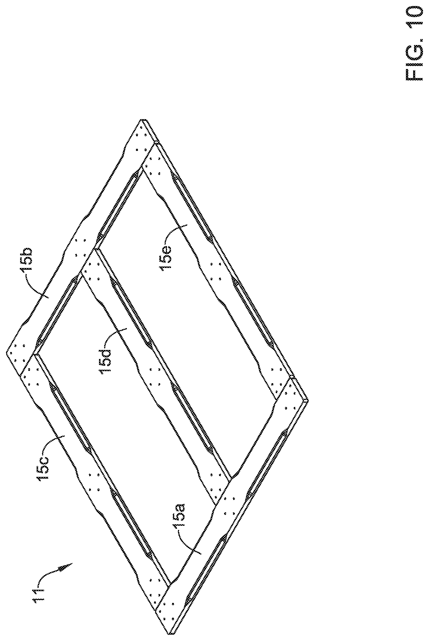
D00013

D00014
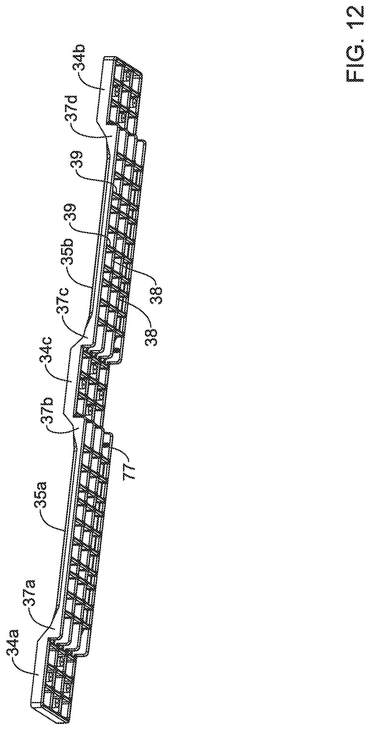
D00015

D00016

D00017

D00018
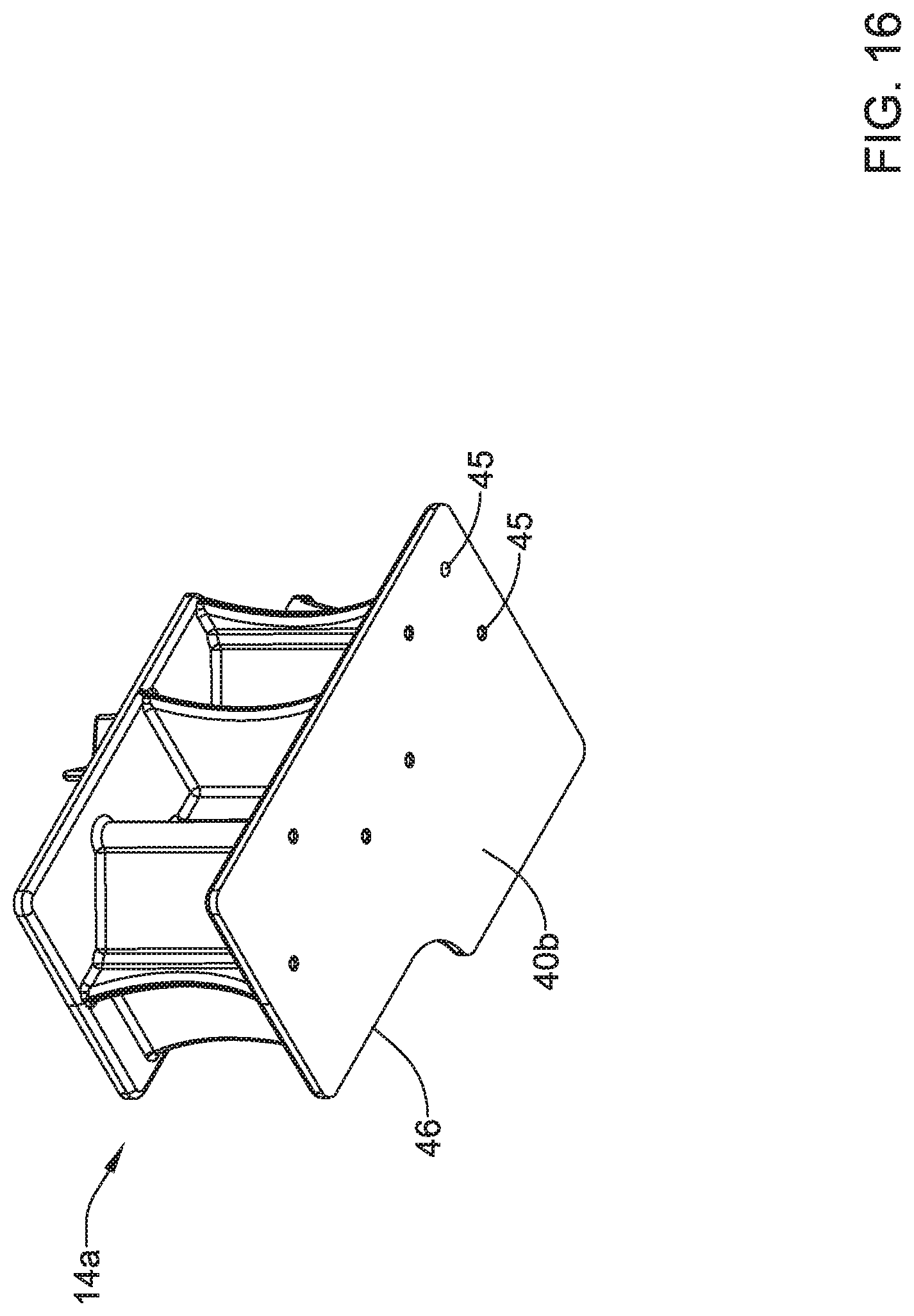
D00019

D00020

D00021

D00022

D00023

D00024

D00025

D00026

D00027
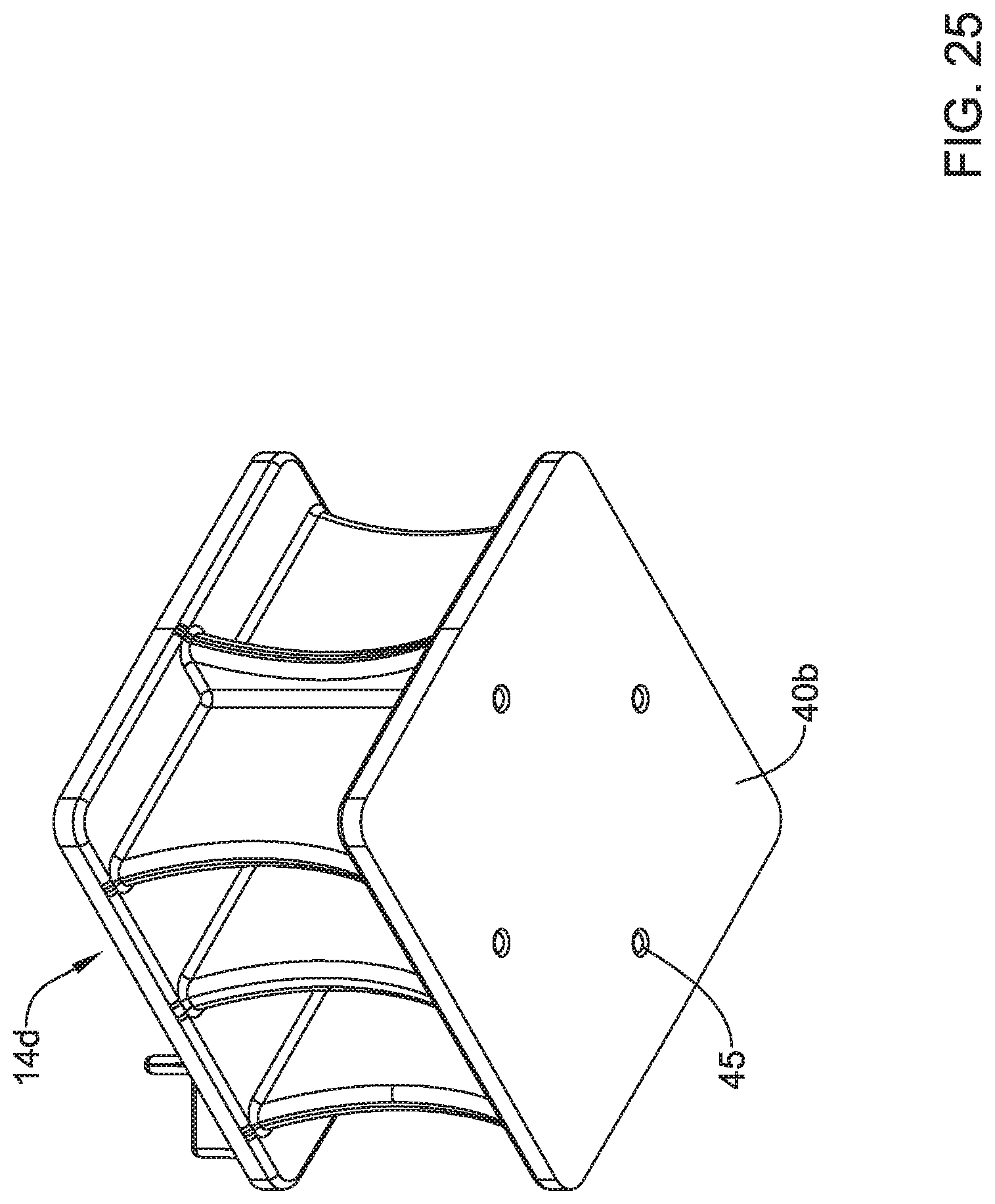
D00028

D00029

D00030
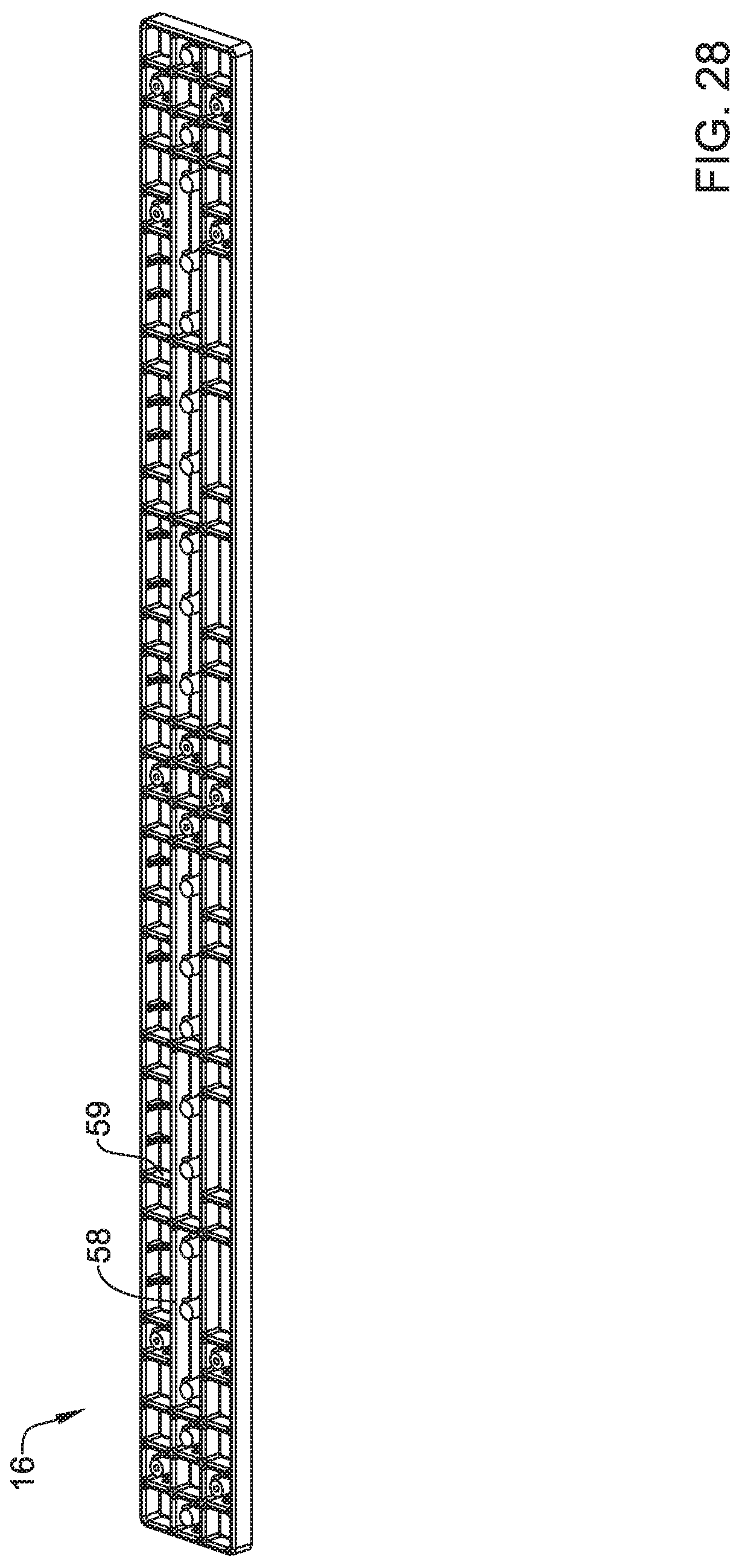
D00031

D00032
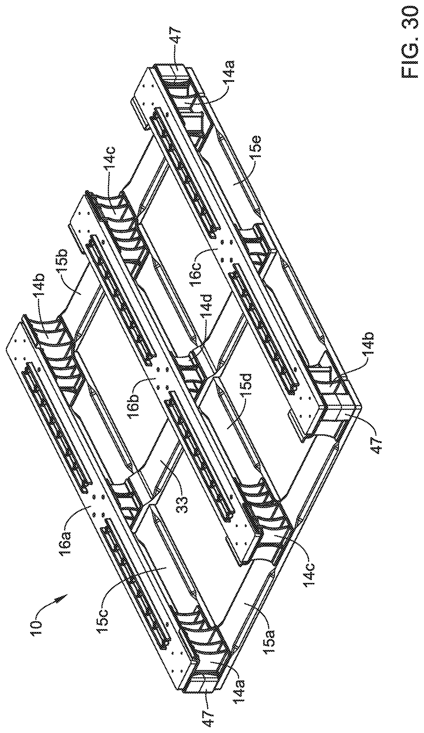
D00033

D00034

D00035

D00036
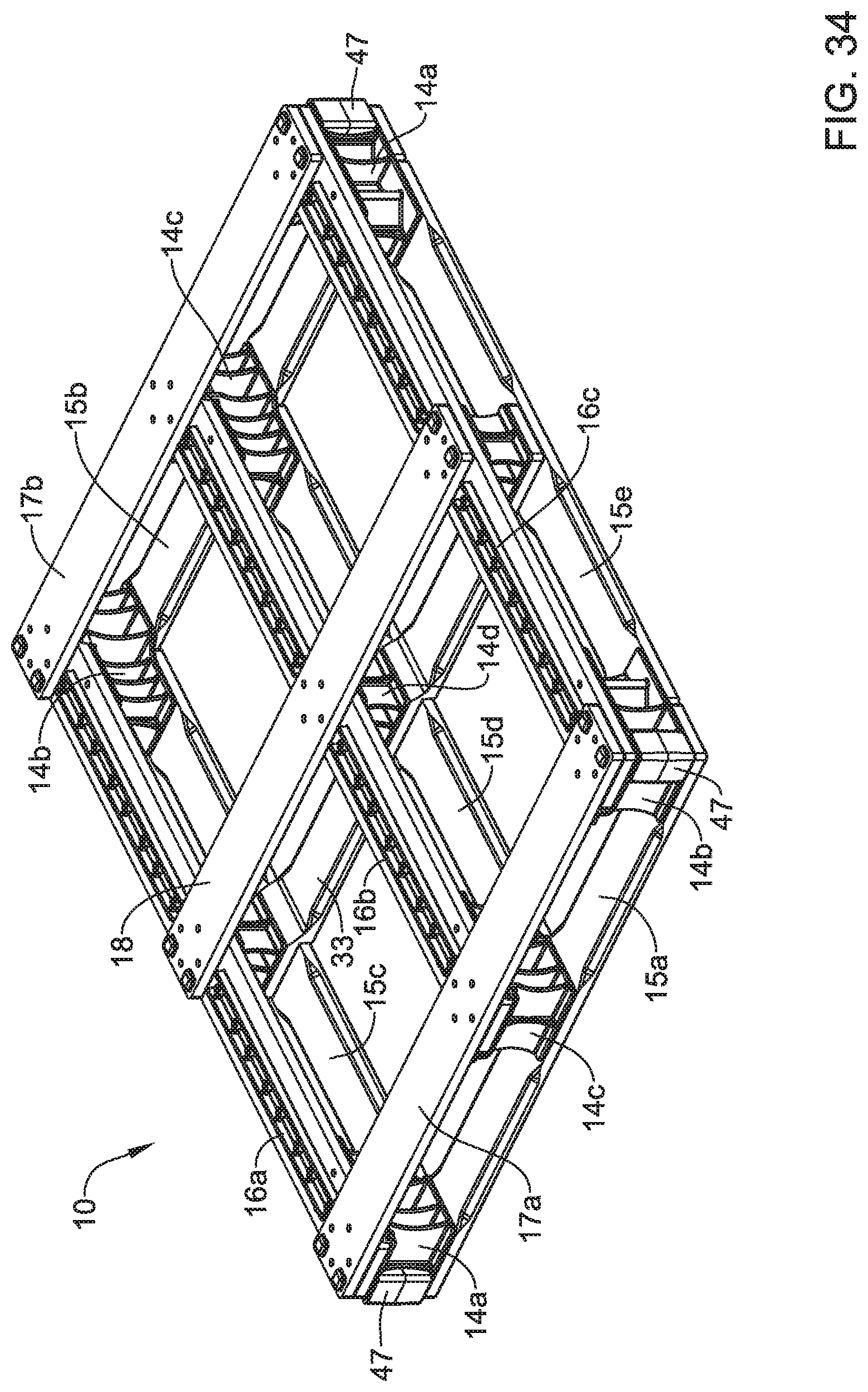
D00037

D00038
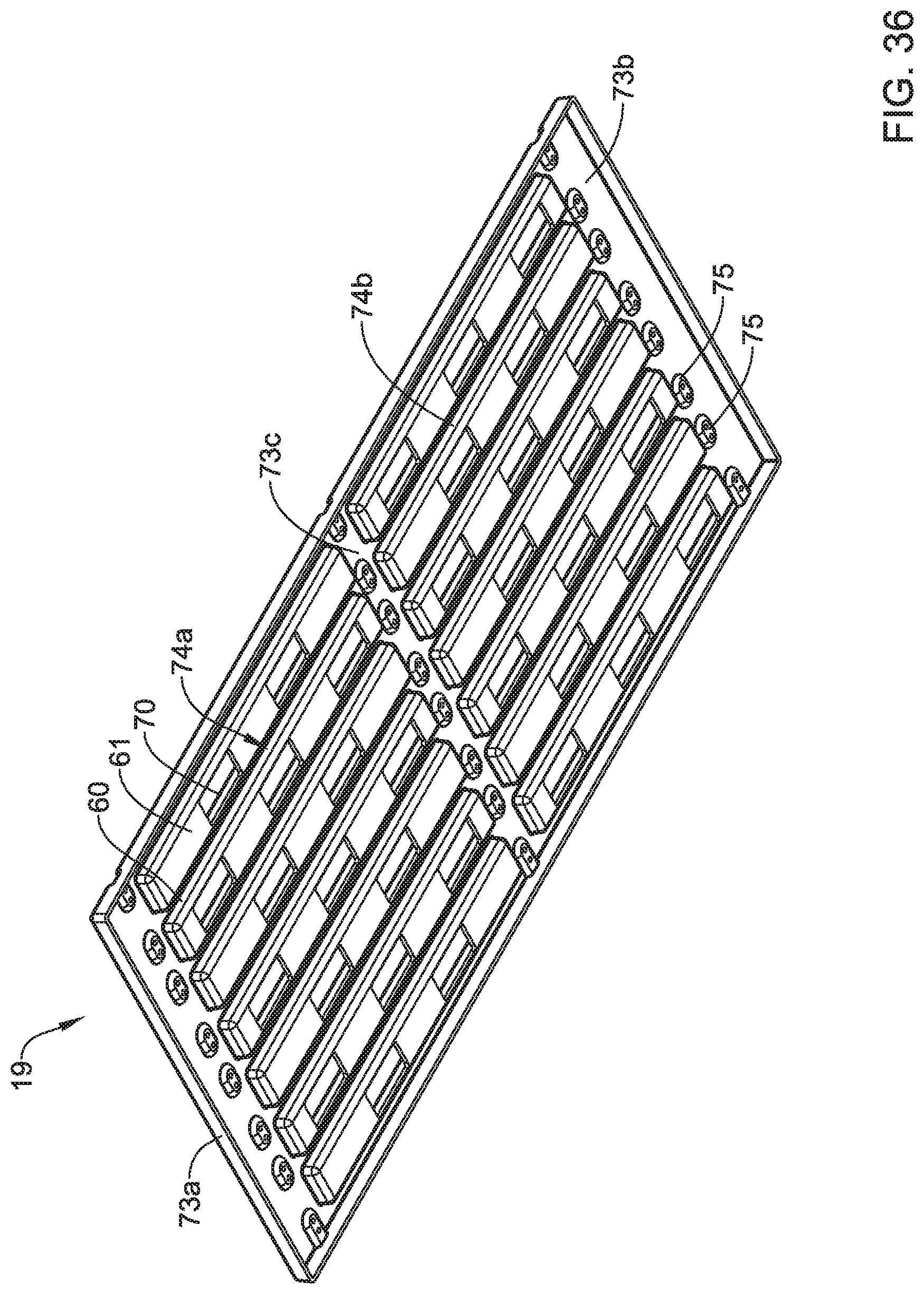
D00039

D00040

D00041

D00042

D00043

D00044

D00045

D00046

D00047

D00048

D00049
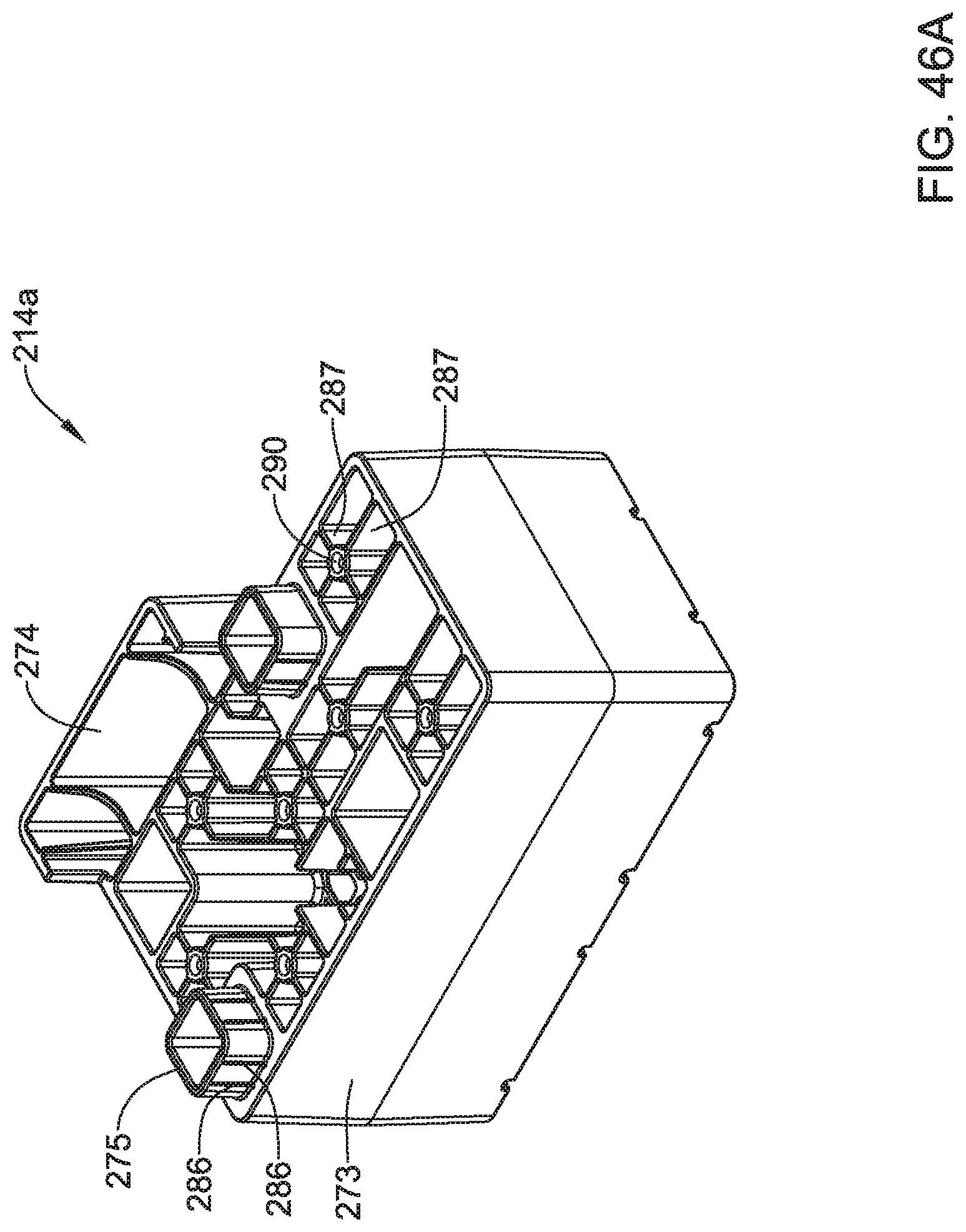
D00050

D00051

D00052

D00053
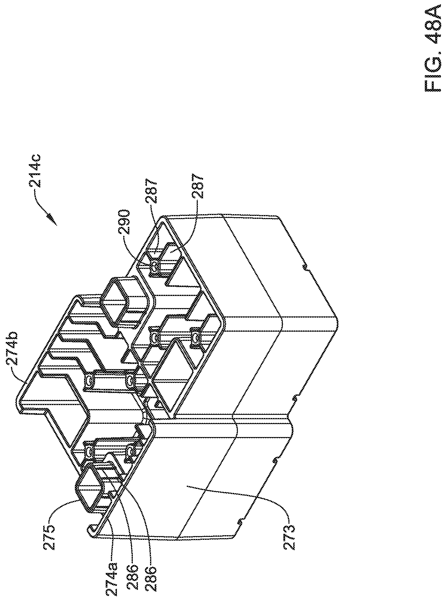
D00054

D00055

D00056

D00057
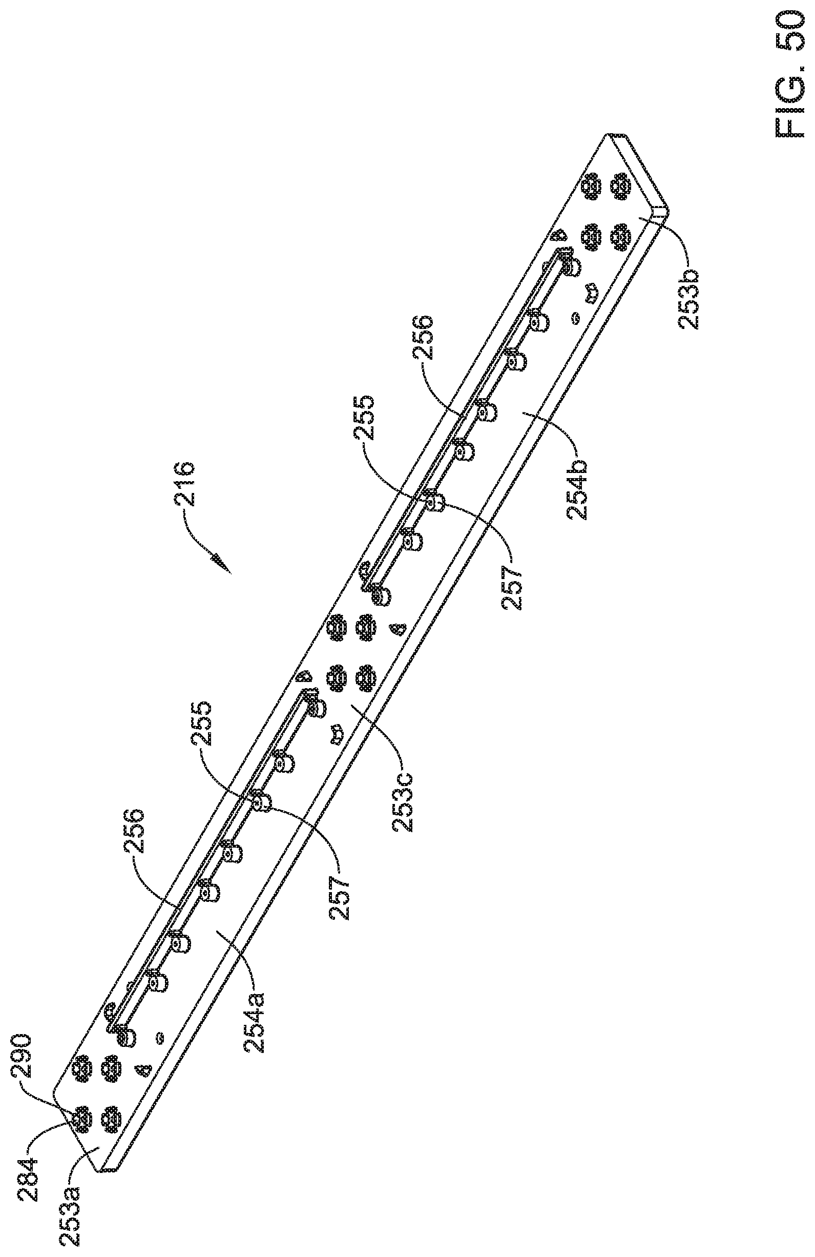
D00058

D00059

D00060
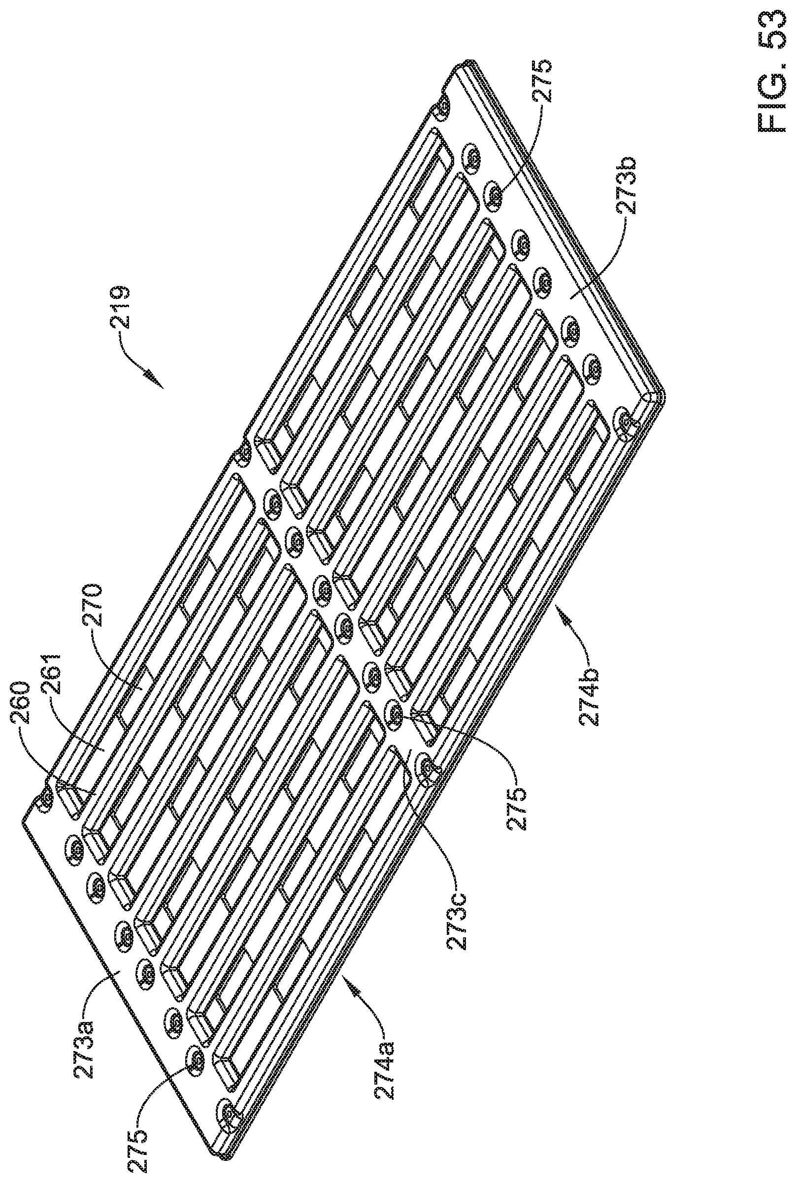
D00061

D00062

D00063

D00064
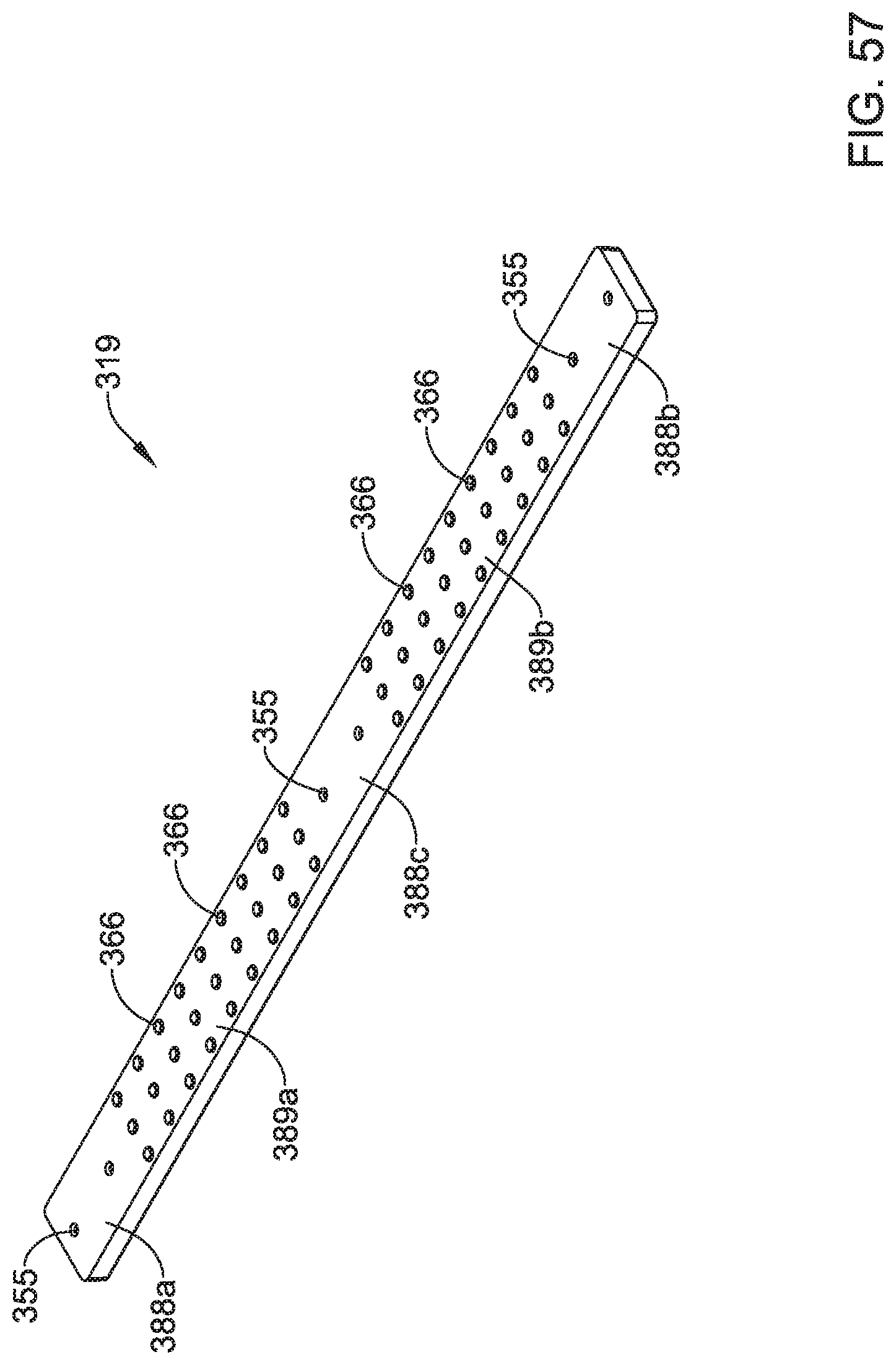
D00065
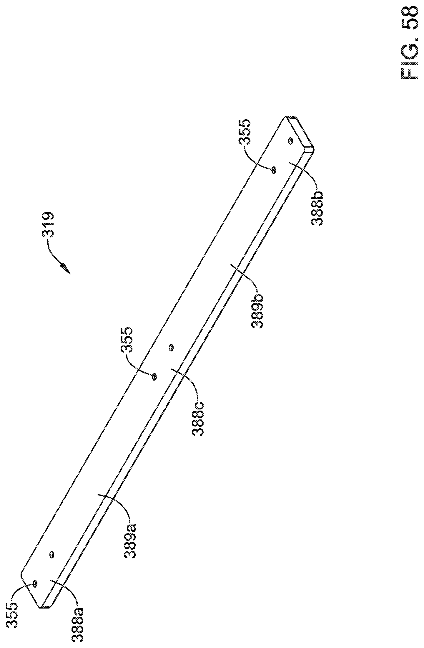
XML
uspto.report is an independent third-party trademark research tool that is not affiliated, endorsed, or sponsored by the United States Patent and Trademark Office (USPTO) or any other governmental organization. The information provided by uspto.report is based on publicly available data at the time of writing and is intended for informational purposes only.
While we strive to provide accurate and up-to-date information, we do not guarantee the accuracy, completeness, reliability, or suitability of the information displayed on this site. The use of this site is at your own risk. Any reliance you place on such information is therefore strictly at your own risk.
All official trademark data, including owner information, should be verified by visiting the official USPTO website at www.uspto.gov. This site is not intended to replace professional legal advice and should not be used as a substitute for consulting with a legal professional who is knowledgeable about trademark law.