Power tool dust collector
Brewster , et al.
U.S. patent number 10,695,880 [Application Number 15/684,671] was granted by the patent office on 2020-06-30 for power tool dust collector. This patent grant is currently assigned to Milwaukee Electric Tool Corporation. The grantee listed for this patent is MILWAUKEE ELECTRIC TOOL CORPORATION. Invention is credited to Michael R. Brewster, Ming Cong Chen, Chin Hung Lam, Kurt Limberg, Brandon L. Verbrugge, Roland Vogele, Brian P. Wattenbach, Tsz Kin Wong.


View All Diagrams
| United States Patent | 10,695,880 |
| Brewster , et al. | June 30, 2020 |
Power tool dust collector
Abstract
A power tool assembly includes a hand-held power tool, a dust collector removably coupled to the power tool, and first and second power tool battery packs each of which is interchangeably coupled with the power tool and the dust collector for separately powering the power tool and the dust collector, respectively.
| Inventors: | Brewster; Michael R. (Wauwatosa, WI), Wong; Tsz Kin (Hong Kong, CN), Lam; Chin Hung (Hong Kong, CN), Wattenbach; Brian P. (Menomonee Falls, WI), Verbrugge; Brandon L. (Brookfield, WI), Vogele; Roland (Winnenden, DE), Limberg; Kurt (Milwaukee, WI), Chen; Ming Cong (Dongguang, CN) | ||||||||||
|---|---|---|---|---|---|---|---|---|---|---|---|
| Applicant: |
|
||||||||||
| Assignee: | Milwaukee Electric Tool
Corporation (Brookfield, WI) |
||||||||||
| Family ID: | 47913012 | ||||||||||
| Appl. No.: | 15/684,671 | ||||||||||
| Filed: | August 23, 2017 |
Prior Publication Data
| Document Identifier | Publication Date | |
|---|---|---|
| US 20170348812 A1 | Dec 7, 2017 | |
Related U.S. Patent Documents
| Application Number | Filing Date | Patent Number | Issue Date | ||
|---|---|---|---|---|---|
| 13604674 | Sep 6, 2012 | 9776296 | |||
| 13349784 | Mar 3, 2015 | 8967923 | |||
| 12991753 | Aug 26, 2014 | 8813868 | |||
| PCT/US2009/043365 | May 8, 2009 | ||||
| 61654296 | Jun 1, 2012 | ||||
| 61611417 | Mar 15, 2012 | ||||
| 61611003 | Mar 14, 2012 | ||||
| 61051892 | May 9, 2008 | ||||
| Current U.S. Class: | 1/1 |
| Current CPC Class: | B23Q 11/00 (20130101); B23Q 11/0046 (20130101); Y02P 70/10 (20151101) |
| Current International Class: | B23Q 11/00 (20060101) |
| Field of Search: | ;173/198-200,171,162.1,170 |
References Cited [Referenced By]
U.S. Patent Documents
| 2041689 | May 1936 | Baumeister |
| 2742105 | April 1956 | Dow |
| 2829867 | April 1958 | Brochetti |
| 3162255 | December 1964 | McCarty |
| 3368633 | February 1968 | Moates |
| 3456740 | July 1969 | Kurt |
| 3533565 | October 1970 | Weiner |
| 3537336 | November 1970 | Schmuck |
| 3776647 | December 1973 | Hart |
| 3837383 | September 1974 | Ko |
| 3850254 | November 1974 | Hirdes |
| 3882644 | May 1975 | Cusumano |
| 3934661 | January 1976 | Sauerwein |
| 3936213 | February 1976 | Kappel |
| 3958474 | May 1976 | Kreitz |
| 3964212 | June 1976 | Karden |
| 4011624 | March 1977 | Proett |
| 4051880 | October 1977 | Hestily |
| 4064952 | December 1977 | Lechner |
| 4097176 | June 1978 | Wanner |
| 4192390 | March 1980 | Reibetanz |
| 4207953 | June 1980 | Reibetanz |
| 4209069 | June 1980 | Smith |
| 4213571 | July 1980 | Deardorff |
| 4250971 | February 1981 | Reibetanz |
| 4251171 | February 1981 | Brett |
| 4276675 | July 1981 | Pioch |
| 4329095 | May 1982 | Schmuck |
| 4361957 | December 1982 | Kroetz |
| 4368556 | January 1983 | Wanner |
| 4515504 | May 1985 | Moore, Sr. |
| D280142 | August 1985 | Pudwill |
| 4615070 | October 1986 | Frederick |
| 4643776 | February 1987 | Hollowell |
| 4766639 | August 1988 | Lindquist |
| 4820090 | April 1989 | Chen |
| 4820315 | April 1989 | DeMarco |
| 4825140 | April 1989 | St. Louis |
| 4881294 | November 1989 | Riedl |
| D305607 | January 1990 | Andrews |
| 4921375 | May 1990 | Famulari |
| 4956892 | September 1990 | Fawkes |
| 4964472 | October 1990 | Cleworth |
| 4967516 | November 1990 | Hoshino |
| D316316 | April 1991 | Yuen |
| 5025870 | June 1991 | Gantner |
| 5061123 | October 1991 | Broussard |
| 5084972 | February 1992 | Waugh |
| 5089738 | February 1992 | Bergqvist |
| 5090499 | February 1992 | Cuneo |
| 5099157 | March 1992 | Meyer |
| 5120983 | June 1992 | Saemann |
| 5129467 | July 1992 | Watanabe |
| 5136750 | August 1992 | Takashima |
| 5199174 | April 1993 | Wild |
| 5199501 | April 1993 | Klueber |
| 5237896 | August 1993 | Albright |
| 5256906 | October 1993 | Tsuge |
| 5292210 | March 1994 | Nowick |
| 5327649 | July 1994 | Skinner |
| 5356245 | October 1994 | Hosoi |
| 5440809 | August 1995 | Padilla |
| 5467835 | November 1995 | Obermeier |
| 5509454 | April 1996 | Giacometti |
| 5545082 | August 1996 | Courson |
| 5606767 | March 1997 | Crlenjak |
| 5674119 | October 1997 | Desrosiers |
| 5688082 | November 1997 | Richardson |
| 5747973 | May 1998 | Robitaille |
| 5765654 | June 1998 | Burger |
| 5813802 | September 1998 | Ajimi |
| 5878607 | March 1999 | Nunes |
| 5881823 | March 1999 | Kabatnik |
| 5899644 | May 1999 | Buck |
| 5904453 | May 1999 | Gavia |
| 5909016 | June 1999 | Sterling |
| 5931072 | August 1999 | Shibata |
| 5940931 | August 1999 | Jeon |
| 5952623 | September 1999 | Sterling |
| 5955791 | September 1999 | Irlander |
| 5983445 | November 1999 | Baker |
| 5988954 | November 1999 | Gaskin |
| 5993122 | November 1999 | Baker |
| 6014811 | January 2000 | Taomo |
| 6027399 | February 2000 | Stewart |
| 6044519 | April 2000 | Hendrix |
| 6053674 | April 2000 | Thompson |
| 6079078 | June 2000 | Byington |
| 6102631 | August 2000 | Nyari |
| 6120363 | September 2000 | Dunn |
| D431766 | October 2000 | Zurwelle |
| 6146066 | November 2000 | Yelton |
| 6167626 | January 2001 | Doumani |
| 6222285 | April 2001 | Haley |
| D442452 | May 2001 | Stirm |
| 6224471 | May 2001 | Clowers |
| 6233831 | May 2001 | Iida |
| 6265091 | July 2001 | Pierson |
| D447032 | August 2001 | Schoen |
| 6379091 | April 2002 | Queipo |
| 6416403 | July 2002 | Chiang |
| 6431040 | August 2002 | Miller |
| 6443675 | September 2002 | Kopras |
| 6443676 | September 2002 | Kopras |
| 6457915 | October 2002 | Kao |
| 6470778 | October 2002 | Kaye, Jr. |
| 6501195 | December 2002 | Barton |
| 6501197 | December 2002 | Cornog |
| 6502949 | January 2003 | Horiyama |
| 6514131 | February 2003 | Reich |
| 6528902 | March 2003 | Barton |
| 6543549 | April 2003 | Riedl |
| 6557261 | May 2003 | Buser |
| 6587184 | July 2003 | Wursch |
| 6595300 | July 2003 | Milbourne |
| 6609860 | August 2003 | Wanek |
| 6615930 | September 2003 | Bongers-Ambrosius |
| 6640384 | November 2003 | Sanders |
| 6641634 | November 2003 | Reich |
| D487686 | March 2004 | Milbourne |
| 6749654 | June 2004 | Hilliard |
| 6776244 | August 2004 | Milbourne |
| D499946 | December 2004 | Stirm |
| 6827640 | December 2004 | Bures |
| 6829804 | December 2004 | Sepke |
| 6830507 | December 2004 | Reich |
| 6848985 | February 2005 | Lamprecht |
| 6851898 | February 2005 | Ege |
| 6854937 | February 2005 | Weiss |
| 6854938 | February 2005 | Kopras |
| 6876173 | April 2005 | Mastaler |
| 6887146 | May 2005 | Staas |
| 6910960 | June 2005 | Reich |
| D507950 | August 2005 | Aglassinger |
| D508388 | August 2005 | Aglassinger |
| 6951439 | October 2005 | Arich |
| D515383 | February 2006 | Aglassinger |
| 7000709 | February 2006 | Milbourne |
| 7014945 | March 2006 | Moores |
| 7017680 | March 2006 | Arich |
| D518347 | April 2006 | Corcoran |
| D520320 | May 2006 | Corcoran |
| 7047647 | May 2006 | Mueller |
| 7118607 | October 2006 | Bott |
| 7118609 | October 2006 | Valentini |
| 7123462 | October 2006 | Uekawa |
| 7175371 | February 2007 | Vidal |
| 7182150 | February 2007 | Grossman |
| 7197826 | April 2007 | Baxivanelis |
| 7220088 | May 2007 | Ferrari |
| 7235006 | June 2007 | Ikeda |
| 7281886 | October 2007 | Stoerig |
| 7296323 | November 2007 | Hayama |
| 7300337 | November 2007 | Sun |
| D559059 | January 2008 | Concari |
| 7323023 | January 2008 | Michele |
| 7325273 | February 2008 | Thanner |
| 7334969 | February 2008 | Wood |
| 7341481 | March 2008 | Spiri |
| 7347651 | March 2008 | Hintze |
| 7354226 | April 2008 | Britz |
| 7371034 | May 2008 | Clark |
| 7396193 | July 2008 | Kesten |
| 7422040 | September 2008 | Thomas |
| 7425109 | September 2008 | Simm |
| 7445655 | November 2008 | Bock |
| 7451791 | November 2008 | Cooper |
| 7455486 | November 2008 | Britz |
| 7465328 | December 2008 | Miller |
| 7475739 | January 2009 | Wuensch |
| D587547 | March 2009 | Aglassinger |
| 7497886 | March 2009 | Walker |
| 7509900 | March 2009 | Young |
| 7510356 | March 2009 | Colon |
| D590225 | April 2009 | Sell |
| 7526833 | May 2009 | Cochran |
| 7526866 | May 2009 | Schnell |
| D593389 | June 2009 | Clayton |
| D593827 | June 2009 | Miller |
| D594304 | June 2009 | Aglassinger |
| 7549826 | June 2009 | Videtto |
| 7553217 | June 2009 | Reich |
| 7609025 | October 2009 | Griffin |
| 7635293 | December 2009 | Sun |
| 7644469 | January 2010 | Beers |
| 7661195 | February 2010 | Wood |
| 7669622 | March 2010 | Liao |
| D615838 | May 2010 | Aglassinger |
| 7719230 | May 2010 | Griffin |
| D618529 | June 2010 | Stirm |
| D618531 | June 2010 | Stirm |
| 7726918 | June 2010 | Onose |
| 7794184 | September 2010 | Di Nicolantonio |
| 7799104 | September 2010 | Valentini |
| 7802505 | September 2010 | Hetcher |
| D625981 | October 2010 | Stirm |
| 7821886 | October 2010 | Yuzuki |
| D626813 | November 2010 | Stirm |
| 7854054 | December 2010 | Kopras |
| 7871311 | January 2011 | Wall |
| 7871313 | January 2011 | Roehm |
| D631720 | February 2011 | Aglassinger |
| D631721 | February 2011 | Aglassinger |
| 7882771 | February 2011 | Sasaki |
| 7887624 | February 2011 | Ekstrom |
| 7905260 | March 2011 | Keenan |
| 7909114 | March 2011 | Nishikawa |
| 7913352 | March 2011 | Ichikawa |
| 7938873 | May 2011 | Fritz |
| 7962994 | June 2011 | Beers |
| 7976363 | July 2011 | Reich |
| 7976364 | July 2011 | Roehm |
| 8015657 | September 2011 | Beers |
| 8016048 | September 2011 | Ueda |
| 8424615 | April 2013 | Baumann |
| 8573323 | November 2013 | Muller |
| 8733470 | May 2014 | Matthias |
| 8813866 | August 2014 | Suzuki |
| 8890468 | November 2014 | Bauer |
| 8901887 | December 2014 | Sever |
| 9009982 | April 2015 | Sedgwick |
| 9409273 | August 2016 | Brown |
| 9579762 | February 2017 | Sullivan |
| 2001/0052429 | December 2001 | Frenzel |
| 2002/0129949 | September 2002 | Bongers-Ambrosius |
| 2002/0145724 | October 2002 | Wursch |
| 2002/0154960 | October 2002 | Lin |
| 2003/0044247 | March 2003 | Wolfe |
| 2004/0060145 | April 2004 | Hayama |
| 2004/0154168 | August 2004 | McDonald |
| 2004/0177980 | September 2004 | Lucas |
| 2004/0251041 | December 2004 | Grossman |
| 2005/0000052 | January 2005 | Byles |
| 2005/0037699 | February 2005 | Park |
| 2005/0055795 | March 2005 | Zeiler |
| 2005/0082920 | April 2005 | Heigl |
| 2005/0105977 | May 2005 | Ishihara |
| 2005/0111214 | May 2005 | Zeiler |
| 2005/0161305 | July 2005 | Jenni |
| 2005/0273969 | December 2005 | Watson |
| 2006/0016043 | January 2006 | Matsuhashi |
| 2006/0091858 | May 2006 | Johnson |
| 2006/0107634 | May 2006 | Ohlendorf |
| 2006/0153650 | July 2006 | Simm |
| 2006/0178087 | August 2006 | Wuensch |
| 2006/0276116 | December 2006 | Reich |
| 2007/0039119 | February 2007 | Zahuranec |
| 2007/0113369 | May 2007 | Cochran |
| 2008/0018303 | January 2008 | Scheucher |
| 2008/0020686 | January 2008 | Reich |
| 2008/0022479 | January 2008 | Zhao |
| 2008/0060149 | March 2008 | Wu |
| 2008/0124181 | May 2008 | Hintze |
| 2008/0189899 | August 2008 | Beers |
| 2008/0202781 | August 2008 | Nishikawa |
| 2008/0209739 | September 2008 | Saitoh |
| 2008/0276776 | November 2008 | Kani |
| 2009/0032138 | February 2009 | Alleman |
| 2009/0100682 | April 2009 | Delfini |
| 2009/0136309 | May 2009 | Coulston |
| 2009/0148246 | June 2009 | Nishikawa |
| 2009/0148248 | June 2009 | Nishikawa |
| 2009/0158904 | June 2009 | Chen |
| 2009/0171243 | July 2009 | Hibner |
| 2009/0181606 | July 2009 | Loveless |
| 2009/0183336 | July 2009 | Kunz |
| 2009/0183614 | July 2009 | Auh |
| 2009/0188691 | July 2009 | Hahn |
| 2009/0214307 | August 2009 | Nguyen |
| 2009/0241283 | October 2009 | Loveless |
| 2010/0000386 | January 2010 | Dagn |
| 2010/0021252 | January 2010 | Leckey |
| 2010/0037571 | February 2010 | Roehm |
| 2010/0072975 | March 2010 | Hori |
| 2010/0155095 | June 2010 | Furusawa |
| 2010/0170538 | July 2010 | Baker |
| 2010/0197209 | August 2010 | Dehde |
| 2010/0260565 | October 2010 | Santamarina |
| 2010/0269647 | October 2010 | Baumann |
| 2010/0316455 | December 2010 | Sanchez |
| 2011/0008117 | January 2011 | Kasuya |
| 2011/0008118 | January 2011 | Yoshikane |
| 2011/0023709 | February 2011 | Bosshard |
| 2011/0079207 | April 2011 | Guth |
| 2011/0081214 | April 2011 | Santamarina |
| 2011/0113587 | May 2011 | Nagasaka |
| 2011/0142558 | June 2011 | Hahn |
| 2011/0147031 | June 2011 | Matthias |
| 2011/0185869 | August 2011 | Wasielewski |
| 2011/0197389 | August 2011 | Ota |
| 2011/0226499 | September 2011 | Kakiuchi |
| 2011/0226502 | September 2011 | Bito |
| 2011/0266015 | November 2011 | Ohlendorf |
| 2011/0266016 | November 2011 | Ohlendorf |
| 2011/0283853 | November 2011 | Aoyama |
| 2011/0308830 | December 2011 | Furusawa |
| 2012/0037385 | February 2012 | Suzuki |
| 2012/0043101 | February 2012 | Ishikawa |
| 2012/0073077 | March 2012 | Ishikawa |
| 2012/0234570 | September 2012 | Machida |
| 2012/0273243 | November 2012 | Tada |
| 2012/0298391 | November 2012 | Kakiuchi |
| 2012/0301762 | November 2012 | Welker |
| 2013/0025893 | January 2013 | Ota |
| 2013/0031879 | February 2013 | Yoshikane |
| 2013/0055523 | March 2013 | Yoshikane |
| 2013/0183111 | July 2013 | Lerch |
| 2013/0187461 | July 2013 | Goto |
| 2013/0213683 | August 2013 | Brewster |
| 2014/0008087 | January 2014 | Brown |
| 2014/0304939 | October 2014 | Suzuki |
| 2016/0023346 | January 2016 | Bernhart |
| 2017/0232565 | August 2017 | Machida |
| 2018/0036852 | February 2018 | Padget |
| 2925908 | Jan 1981 | DE | |||
| 3202737 | Aug 1983 | DE | |||
| 10342507 | Apr 2005 | DE | |||
| 102004025880 | Nov 2005 | DE | |||
| 102004026038 | Feb 2006 | DE | |||
| 202006017578 | Mar 2007 | DE | |||
| 102006029624 | Jan 2008 | DE | |||
| 102007036783 | Feb 2009 | DE | |||
| 426321 | May 1991 | EP | |||
| 434295 | Jun 1991 | EP | |||
| 601805 | Jun 1994 | EP | |||
| 855247 | Jul 1998 | EP | |||
| 958878 | Nov 1999 | EP | |||
| 1293298 | Sep 2005 | EP | |||
| 1623793 | Feb 2006 | EP | |||
| 1245330 | Mar 2006 | EP | |||
| 1459841 | Aug 2006 | EP | |||
| 1459842 | Aug 2006 | EP | |||
| 1506840 | Mar 2007 | EP | |||
| 1600255 | Jul 2007 | EP | |||
| 1281486 | Nov 2007 | EP | |||
| 1477272 | Oct 2009 | EP | |||
| 2383072 | Nov 2011 | EP | |||
| 1872900 | Jul 2012 | EP | |||
| 2080476 | Aug 2012 | EP | |||
| 2383071 | Dec 2012 | EP | |||
| 2363237 | Jan 2014 | EP | |||
| 1569532 | Jun 1980 | GB | |||
| 2441224 | Dec 2008 | GB | |||
Other References
|
DE 102010010113.3-15 German Search Report dated Oct. 29, 2010, 3 pages. cited by applicant . Dewalt, D25300DH Dust Extraction System (HEPA Filter) for 2 kg L-Shape Hammer, catalog, (2011), 1 page. cited by applicant . Dewalt, D25302DH Dust Extraction System for 36V SDS Rotary Hammer, catalog, (2011), 1 page. cited by applicant . Dewalt, D25302DH Dust Extraction System with HEPA Filter, Instruction Manual, (2006), 6 page. cited by applicant . English translation of EP2363237. cited by applicant . EP 111559340 European Search Report dated Jun. 28, 2011, 6 pages. cited by applicant. |
Primary Examiner: Long; Robert F
Attorney, Agent or Firm: Michael Best & Friedrich LLP
Parent Case Text
CROSS-REFERENCE TO RELATED APPLICATIONS
This application is a continuation of U.S. patent application Ser. No. 13/604,674 filed Sep. 6, 2012, now U.S. Pat. No. 9,776,296, which claims priority to U.S. Provisional Patent Application No. 61/654,296 filed Jun. 1, 2012; 61/611,417 filed Mar. 15, 2012; and 61/611,003 filed Mar. 14, 2012, the entire contents of all of which are incorporated herein by reference.
U.S. patent application Ser. No. 13/604,674 is also a continuation-in-part of U.S. patent application Ser. No. 13/349,784 filed Jan. 13, 2012, now U.S. Pat. No. 8,967,923, the entire content of which is incorporated herein by reference.
Further, U.S. patent application Ser. No. 13/604,674 is a continuation-in-part of U.S. patent application Ser. No. 12/991,753 filed Jan. 31, 2011, now U.S. Pat. No. 8,813,868, which is a national stage entry under 35 U.S.C. .sctn. 371 of International Patent Application No. PCT/US09/43365 filed May 8, 2009, which claims priority to U.S. Provisional Patent Application No. 61/051,892 filed May 9, 2008, the entire contents of all of which are incorporated herein by reference.
Claims
What is claimed is:
1. A power tool assembly, comprising: a hand-held power tool; a dust collector removably coupled to the power tool; and, wherein the dust collector further includes a housing, a telescoping suction pipe coupled to the housing, an electric motor positioned in the housing, a suction fan driven by the electric motor and operable to generate a vacuum in the suction pipe, a dust container coupled to the housing and positioned upstream of the suction fan, an adapter including a first portion coupled to the housing and a second portion, and an auxiliary handle coupled to the second portion of the adapter and the power tool, the adapter and the auxiliary handle supporting the power tool, wherein the power tool is positioned adjacent the dust collector, wherein the auxiliary handle includes a cylindrical band received within an arcuate slot in the adapter and a rotatable grip for constricting and expanding the band, and wherein a neck of the power tool is clamped by the band; and first and second power tool battery packs each of which is interchangeably coupled with the power tool and the dust collector for separately powering the power tool and the dust collector, respectively.
2. The power tool assembly of claim 1, wherein the first and second power tool battery packs are identical.
3. The power tool assembly of claim 1, wherein the power tool and the dust collector are coupled in a side-by-side relationship.
4. The power tool assembly of claim 1, wherein each of the first and second battery packs includes three lithium-ion battery cells.
5. The power tool assembly of claim 1, wherein the power tool is a rotary power tool.
6. The power tool assembly of claim 5, wherein the rotary power tool is one of a rotary hammer and a hammer drill.
7. The power tool assembly of claim 1, wherein the telescoping suction pipe is configured to telescope along a first axis, and wherein the second battery pack is removably coupled to the housing along a second axis oriented substantially normal to the first axis.
8. The power tool assembly of claim 7, wherein the power tool is a rotary power tool defining a rotational axis, and wherein the first axis is substantially parallel with the rotational axis of the power tool.
9. The power tool assembly of claim 1, wherein the housing includes a first side and an opposite second side, and wherein the first portion of the adapter is interchangeably connectable to the first and second sides of the housing to thereby support the power tool adjacent a chosen one of the first and second sides of the housing.
10. The power tool assembly of claim 9, further comprising a suction head coupled to a distal end of the suction pipe, wherein the suction head is repositionable between first and second orientations to accommodate placement of the power tool adjacent the first and second sides of the housing, respectively.
11. The power tool assembly of claim 10, wherein the suction head is coupled to the distal end of the suction pipe between the first and second orientations.
12. The power tool assembly of claim 11, further comprising a detent arrangement for maintaining the suction head in at least one of the first and second orientations.
13. The power tool assembly of claim 12, wherein the detent arrangement includes first and second detent members on the suction head, and first and second detent recesses positioned on opposite sides of the suction pipe, wherein the first detent member is received in the first detent recess to maintain the suction head in the first orientation, and wherein the second detent member is received in the second detent recess to maintain the suction head in the second orientation.
14. The power tool assembly of claim 13, further comprising an end cap coupled to the distal end of the suction pipe between the suction pipe and the suction head, wherein the first and second recesses are both defined in the end cap.
15. The power tool assembly of claim 9, wherein the adapter includes a fixed clamp member and an opposed, movable clamp member for clamping the adapter to one of the first and second sides of the housing.
16. The power tool assembly of claim 15, wherein each of the first and second sides of the housing includes a first notch in which the fixed clamp member is received, and a second notch in which the movable clamp member is received.
17. The power tool assembly of claim 16, wherein the adapter includes a cam and a follower for actuating the movable clamp member between an open position in which it is displaced from the second notch and disengaged from the housing, and a closed position in which the movable clamp member is received within the second notch and engaged with the housing.
18. The power tool assembly of claim 17, wherein the movable clamp member is integrally formed with the follower as a single piece.
19. The power tool assembly of claim 17, wherein the adapter includes a resilient member that biases the movable clamp member away from the fixed clamp member and toward the open position.
20. The power tool assembly of claim 1, wherein the handle includes a shaft extending from the second portion of the adapter and a clamp member movable relative to the shaft, and wherein the power tool is clamped between the movable clamp member and the adapter.
21. The power tool assembly of claim 20, wherein the adapter includes a fixed clamp member, and wherein the power tool is clamped between the movable clamp member and the fixed clamp member.
22. The power tool assembly of claim 21, wherein the shaft includes a threaded portion, wherein the handle includes a grip having therein a threaded insert engaged with the threaded portion of the shaft, and wherein the movable clamp member is movable along the shaft in response to relative rotation between the grip and the shaft for clamping the power tool between the movable clamp member and the fixed clamp member.
23. The power tool assembly of claim 22, wherein the handle includes a spacer positioned between the movable clamp member and the grip.
24. The power tool assembly of claim 1, wherein the dust collector further includes a switch electrically connecting the motor with the second battery to activate the motor in response to detecting telescoping movement of the suction pipe relative to the housing.
25. The power tool assembly of claim 24, wherein the switch is a first switch, wherein the dust collector further includes a second switch electrically connected with the motor, the second battery, and the first switch, and wherein the second switch is toggled between a first switching position in which the electric motor remains deactivated irrespective of actuation of the first switch, a second switching position in which the electric motor may be activated and deactivated automatically in response to actuation of the first switch, and a third switching position in which the electric motor may be activated irrespective of actuation of the first switch.
26. The power tool assembly of claim 25, further comprising: a suction head removably coupled to the suction pipe, the suction head including a suction inlet through which a tool bit of the power tool is extendable, and a nozzle interchangeably coupled to the suction pipe with the suction head, the nozzle being usable with the dust collector without the power tool when the second switch is in the third switching position.
27. The power tool assembly of claim 25, further comprising an extension stop adjustably coupled along the length of the suction pipe to limit an extent to which the suction pipe telescopes from the housing, wherein the first switch is actuated by the extension stop.
28. The power tool assembly of claim 27, wherein the first switch is a normally closed microswitch, and wherein the microswitch is actuated to an open state in response to contact with the extension stop.
29. The power tool assembly of claim 28, wherein the microswitch is actuated to a closed state in response to a loss of contact with the extension stop.
30. The power tool assembly of claim 24, wherein the suction pipe is telescopically movable relative to the housing from an extended position to a retracted position in response to being depressed against a workpiece, and wherein the switch electrically connects the motor with the second battery in response to the switch detecting movement of the suction pipe from the extended position to the retracted position.
31. The power tool assembly of claim 30, further comprising a controller electrically connected with the switch and the second battery.
32. The power tool assembly of claim 31, wherein the controller maintains activation of the motor for a period of time in response to the switch detecting movement of the suction pipe from the retracted position to the extended position for clearing dust from the suction pipe.
33. The power tool assembly of claim 32, wherein the controller initiates a timer upon detecting movement of the suction pipe from the extended position to the retracted position, and wherein the controller maintains activation of the motor for clearing dust from the suction pipe only after a predetermined amount of time lapses with the suction pipe maintained in the retracted position.
34. The power tool assembly of claim 1, wherein the dust collector further includes a filter supported by at least one of the housing and the dust container, the filter being removable from the one of the housing and the dust container for at least one of servicing and replacement.
35. The power tool assembly of claim 34, wherein the filter is removably received in the dust container.
36. The power tool assembly of claim 35, wherein the dust container and the filter are removable from the housing as a unit.
37. The power tool assembly of claim 35, wherein the filter includes a pleated element and a rim surrounding the pleated element, and wherein the rim is trapped between the dust container and the housing when the dust container is attached to the housing.
38. The power tool assembly of claim 37, wherein the pleated element extends into an interior of the dust container.
39. The power tool assembly of claim 38, wherein the filter is oriented relative to the dust container in an inclined or an oblique manner relative to a longitudinal axis of the suction pipe.
40. The power tool assembly of claim 37, wherein the rim is accessible for grasping to facilitate removal of the filter from the dust container when the dust container is detached from the housing.
41. The power tool assembly of claim 34, wherein the dust collector further includes a detector coupled to the housing and biased toward a first position in which a portion of the detector protrudes from the housing to prevent the dust container from being coupled to the housing in absence of the filter, the protruding portion of the detector being retractable into the housing in response to the detector being moved to a second position by the filter when the filter is present, thereby permitting the dust container to be coupled to the housing.
42. The power tool assembly of claim 41, wherein the detector is pivotably supported by the housing at a location upstream of the suction fan.
43. The power tool assembly of claim 41, wherein the detector includes a shaft defining a rotational axis about which the detector is pivotable and an arm extending radially from the shaft, and wherein the arm is engaged with the filter when the filter is present.
44. The power tool assembly of claim 43, wherein the protruding portion is configured as a finger positioned adjacent the arm.
45. The power tool assembly of claim 44, wherein the housing includes an aperture aligned with the finger, and wherein the dust container includes an alignment tab that is receivable in the aperture when the pre-assembled filter and dust container are attached to the housing.
46. The power tool assembly of claim 45, wherein the finger is pivoted to a position in which it at least partially protrudes into the aperture in absence of the filter, thereby interfering with the alignment tab to prevent the dust container from being attached to the housing.
47. The power tool assembly of claim 1, wherein the power tool is a first power tool and the auxiliary handle is a first auxiliary handle, and wherein the dust collector further includes a handle assembly including the first auxiliary handle, which has a head portion with a first size for receiving a neck of a first power tool for supporting the first power tool in a side-by-side relationship with the dust collector, and a second auxiliary handle having a head portion with a second size for receiving a neck of a second power tool for supporting the second power tool in a side-by-side relationship with the dust collector, the necks of the first and second power tools being of a different size.
48. The power tool assembly of claim 47, wherein the handle assembly further includes a first adapter attached to the first auxiliary handle, and a second adapter attached to the second auxiliary handle, wherein the first and second adapters interchangeably attach the respective first and second auxiliary handles to the housing.
49. The power tool assembly of claim 48, wherein the handle assembly further includes a third auxiliary handle having a head portion with a third size for receiving a neck of a third power tool for supporting the third power tool in a side-by-side relationship with the dust collector, and wherein the necks of the first, second, and third power tools are of a different size.
50. The power tool assembly of claim 49, wherein the handle assembly further includes a third adapter attached to the third auxiliary handle, and wherein the third adapter interchangeably attaches the third auxiliary handle to the housing.
51. The power tool assembly of claim 48, wherein the housing includes a first side and an opposite second side, and wherein the first and second adapters are each interchangeably connectable to the first and second sides of the housing to thereby support one of the first and second power tools adjacent a chosen one of the first and second sides of the housing.
52. The power tool assembly of claim 48, wherein the second auxiliary handle includes a cylindrical band and a rotatable grip for constricting and expanding the band, and wherein the necks of the first and second power tools are clamped by the respective bands of the first and second auxiliary handles.
53. The power tool assembly of claim 52, wherein the respective cylindrical bands of the first and second auxiliary handles include different circumferential lengths.
54. The power tool assembly of claim 1, wherein the dust collector includes a depth stop movable along the length of the suction pipe and selectively fixed to the suction pipe to limit the extent to which the suction pipe may telescope relative to the housing, and a ruler coupled for movement with the depth stop.
55. The power tool assembly of claim 54, wherein the ruler includes a plurality of reference markings, and wherein a first of the markings is alignable with a reference datum on the housing to limit an extent to which the suction pipe telescopes into the housing to a first depth.
56. The power tool assembly of claim 55, wherein a second of the markings is alignable with the reference datum on the housing to limit the extent to which the suction pipe telescopes into the housing to a second depth.
57. The power tool assembly of claim 54, wherein the depth stop is engageable with the housing to limit the extent to which the suction pipe may telescope relative to the housing.
58. A power tool assembly, comprising: a hand-held power tool; a dust collector removably coupled to the power tool; and first and second power tool battery packs each of which is interchangeably coupled with the power tool and the dust collector for separately powering the power tool and the dust collector, respectively, wherein the dust collector further includes a housing, a telescoping suction pipe coupled to the housing, an electric motor positioned in the housing, a suction fan driven by the electric motor and operable to generate a vacuum in the suction pipe, and a switch electrically connecting the motor with the second power tool battery pack to activate the motor in response to detecting telescoping movement of the suction pipe relative to the housing, wherein the switch is a first switch, wherein the dust collector further includes a second switch electrically connected with the motor, the second power tool battery pack, and the first switch, and wherein the second switch is toggled between a first switching position in which the electric motor remains deactivated irrespective of actuation of the first switch, a second switching position in which the electric motor may be activated and deactivated automatically in response to actuation of the first switch, and a third switching position in which the electric motor may be activated irrespective of actuation of the first switch.
59. The power tool assembly of claim 58, further comprising: a suction head removably coupled to the suction pipe, the suction head including a suction inlet through which a tool bit of the power tool is extendable, and a nozzle interchangeably coupled to the suction pipe with the suction head, the nozzle being usable with the dust collector without the power tool when the second switch is in the third switching position.
60. The power tool assembly of claim 58, further comprising an extension stop adjustably coupled along the length of the suction pipe to limit an extent to which the suction pipe telescopes from the housing, wherein the first switch is actuated by the extension stop.
61. The power tool assembly of claim 60, wherein the first switch is a normally closed microswitch, and wherein the microswitch is actuated to an open state in response to contact with the extension stop.
62. The power tool assembly of claim 61, wherein the microswitch is actuated to a closed state in response to a loss of contact with the extension stop.
63. The power tool assembly of claim 58, wherein the suction pipe is telescopically movable relative to the housing from an extended position to a retracted position in response to being depressed against a workpiece, and wherein the switch electrically connects the motor with the second power tool battery pack in response to the switch detecting movement of the suction pipe from the extended position to the retracted position.
64. The power tool assembly of claim 63, further comprising a controller electrically connected with the switch and the second power tool battery pack.
65. The power tool assembly of claim 64, wherein the controller maintains activation of the motor for a period of time in response to the switch detecting movement of the suction pipe from the retracted position to the extended position for clearing dust from the suction pipe.
66. The power tool assembly of claim 65, wherein the controller initiates a timer upon detecting movement of the suction pipe from the extended position to the retracted position, and wherein the controller maintains activation of the motor for clearing dust from the suction pipe only after a predetermined amount of time lapses with the suction pipe maintained in the retracted position.
67. A power tool assembly, comprising: a hand-held power tool; a dust collector removably coupled to the power tool, wherein the dust collector further includes a housing, a telescoping suction pipe coupled to the housing, an electric motor positioned in the housing, a suction fan driven by the electric motor and operable to generate a vacuum in the suction pipe, a dust container coupled to the housing and positioned upstream of the suction fan, and a filter supported by at least one of the housing and the dust container, the filter being removable from the one of the housing and the dust container for at least one of servicing and replacement, wherein the filter is removably received in the dust container, wherein the filter includes a pleated element and a rim surrounding the pleated element, and wherein the rim is trapped between the dust container and the housing when the dust container is attached to the housing; and first and second power tool battery packs each of which is interchangeably coupled with the power tool and the dust collector for separately powering the power tool and the dust collector, respectively.
68. The power tool assembly of claim 67, wherein the dust container and the filter are removable from the housing as a unit.
69. The power tool assembly of claim 67, wherein the pleated element extends into an interior of the dust container.
70. The power tool assembly of claim 69, wherein the filter is oriented relative to the dust container in an inclined or an oblique manner relative to a longitudinal axis of the suction pipe.
71. The power tool assembly of claim 67, wherein the rim is accessible for grasping to facilitate removal of the filter from the dust container when the dust container is detached from the housing.
72. The power tool assembly of claim 67, wherein the dust collector further includes a detector coupled to the housing and biased toward a first position in which a portion of the detector protrudes from the housing to prevent the dust container from being coupled to the housing in absence of the filter, the protruding portion of the detector being retractable into the housing in response to the detector being moved to a second position by the filter when the filter is present, thereby permitting the dust container to be coupled to the housing.
73. The power tool assembly of claim 72, wherein the detector is pivotably supported by the housing at a location upstream of the suction fan.
74. The power tool assembly of claim 72, wherein the detector includes a shaft defining a rotational axis about which the detector is pivotable and an arm extending radially from the shaft, and wherein the arm is engaged with the filter when the filter is present.
75. The power tool assembly of claim 74, wherein the protruding portion is configured as a finger positioned adjacent the arm.
76. The power tool assembly of claim 75, wherein the housing includes an aperture aligned with the finger, and wherein the dust container includes an alignment tab that is receivable in the aperture when the pre-assembled filter and dust container are attached to the housing.
77. The power tool assembly of claim 76, wherein the finger is pivoted to a position in which it at least partially protrudes into the aperture in absence of the filter, thereby interfering with the alignment tab to prevent the dust container from being attached to the housing.
Description
FIELD OF THE INVENTION
The present invention relates to power tools, and more particularly to dust collectors for use with power tools.
BACKGROUND OF THE INVENTION
Dust collectors are typically used in tandem with hand-held drilling tools such as rotary hammers to collect dust and other debris during a drilling operation to prevent dust and other debris from accumulating at a worksite. Such dust collectors may be attached to a rotary hammer to position a suction inlet of the collector proximate a drill bit attached to the rotary hammer. Such dust collectors may also include an on-board dust container in which dust and other debris is accumulated. Such dust containers are often removable from the dust collector to facilitate disposal of the accumulated dust and debris.
SUMMARY OF THE INVENTION
The invention provides, in one aspect, a power tool assembly including a hand-held power tool, a dust collector removably coupled to the power tool, and first and second power tool battery packs each of which is interchangeably coupled with the power tool and the dust collector for separately powering the power tool and the dust collector, respectively.
The invention provides, in another aspect, a dust collector for use with a hand-held power tool. The dust collector includes a housing, a telescoping suction pipe coupled to the housing, an electric motor positioned in the housing, a suction fan driven by the electric motor and operable to generate a vacuum in the suction pipe, a dust container coupled to the housing and positioned upstream of the suction fan, an adapter including a first portion coupled to the housing and a second portion, and an auxiliary handle coupled to the second portion of the adapter and a neck of the power tool. The adapter and the auxiliary handle support the power tool in a side-by-side relationship with the dust collector.
The invention provides, in yet another aspect, a dust collector for use with a hand-held power tool. The dust collector includes a housing, a telescoping suction pipe coupled to the housing, an electric motor positioned in the housing, a suction fan driven by the electric motor and operable to generate a vacuum in the suction pipe, and a switch electrically connecting the motor with a power source to activate the motor in response to detecting telescoping movement of the suction pipe relative to the housing.
The invention provides, in a further aspect, a dust collector including a housing, a telescoping suction pipe coupled to the housing, an electric motor positioned in the housing, a suction fan driven by the electric motor and operable to generate a vacuum in the suction pipe, and a handle assembly. The handle assembly includes a first handle having a head portion with a first size for receiving a neck of a first power tool for supporting the first power tool in a side-by-side relationship with the dust collector and a second handle having a head portion with a second size for receiving a neck of a second power tool for supporting the second power tool in a side-by-side relationship with the dust collector. The necks of the first and second power tools are of a different size.
The invention provides, in another aspect, a dust collector for use with a hand-held power tool. The dust collector includes a housing, a telescoping suction pipe coupled to the housing, an electric motor positioned in the housing, a suction fan driven by the electric motor and operable to generate a vacuum in the suction pipe, a dust container coupled to the housing and positioned upstream of the suction fan, and a filter supported by at least one of the housing and the dust container. The filter is removable from the one of the housing and the dust container for at least one of servicing and replacement.
The invention provides, in yet another aspect, a dust collector for use with a hand-held power tool. The dust collector includes a housing, a suction pipe coupled to the housing for telescoping movement along a first axis, an electric motor positioned in the housing, a suction fan driven by the electric motor and operable to generate a vacuum in the suction pipe, and a battery pack removably coupled to the housing along a second axis oriented substantially normal to the first axis.
The invention provides, in a further aspect, a dust collector for use with a hand-held power tool. The dust collector includes a housing, a telescoping suction pipe coupled to the housing, an electric motor positioned in the housing, a suction fan driven by the electric motor and operable to generate a vacuum in the suction pipe, a depth stop movable along the length of the suction pipe and selectively fixed to the suction pipe to limit the extent to which the suction pipe may telescope relative to the housing, and a ruler coupled for movement with the depth stop.
The invention provides, in another aspect, a dust collector for use with a hand-held power tool. The dust collector includes a housing, a telescoping suction pipe coupled to the housing, an electric motor positioned in the housing, a suction fan driven by the electric motor and operable to generate a vacuum in the suction pipe, a dust container removably coupled to the housing in which dust may be accumulated, a filter supportable by at least one of the housing and the dust container, and a detector coupled to the housing and biased toward a first position in which a portion of the detector protrudes from the housing to prevent the container from being coupled to the housing in absence of the filter. The portion of the detector is retractable into the housing in response to the detector being moved to a second position by the filter when the filter is present, thereby permitting the container to be coupled to the housing.
Other features and aspects of the invention will become apparent by consideration of the following detailed description and accompanying drawings.
BRIEF DESCRIPTION OF THE DRAWINGS
FIG. 1 is a partially cutaway, perspective view of a dust collector in accordance with an embodiment of the invention attached to a rotary power tool.
FIG. 2 is a top view of the dust collector and rotary power tool of FIG. 1.
FIG. 3 is a bottom view of the dust collector and rotary power tool of FIG. 1.
FIG. 4 is a front view of the dust collector and rotary power tool of FIG. 1.
FIG. 5 is a front perspective view of a dust collector in accordance with another embodiment of the invention attached to a rotary power tool.
FIG. 6 is a rear perspective view of the dust collector and rotary power tool of FIG. 5.
FIG. 7 is a rear perspective view of the dust collector of FIG. 5 attached to an opposite side of the rotary power tool.
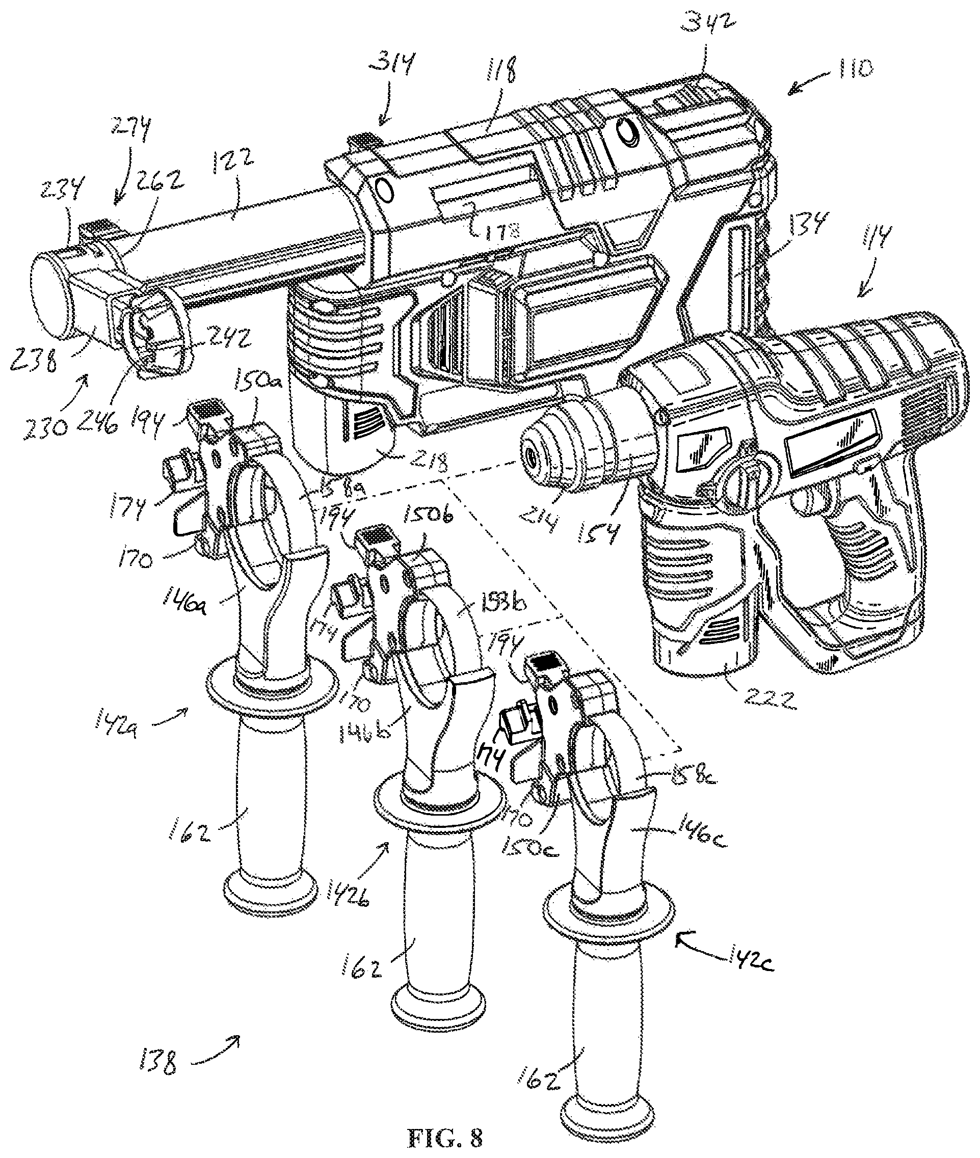
FIG. 8 is a front perspective view of the dust collector of FIG. 5, illustrating a handle assembly having multiple size handles for attaching rotary power tools of different sizes.
FIG. 9 is an enlarged, partial cross-sectional view of an adapter for use with any of the handles of FIG. 8.
FIG. 10 is an enlarged, front perspective view of the dust collector of FIG. 5, illustrating a suction head rotated to a first position relative to a suction pipe.
FIG. 11 is an enlarged, front perspective view of the dust collector of FIG. 5, illustrating the suction head rotated to a second position relative to the suction pipe.
FIG. 12 is an enlarged, front perspective view of the dust collector of FIG. 5, illustrating the suction head and a stand-alone nozzle being interchangeably coupled to the suction pipe.
FIG. 13 is an enlarged, exploded perspective view of the dust collector of FIG. 5, illustrating a dust container and a filter.
FIG. 14 is a longitudinal cross-sectional view of the dust collector of FIG. 5.
FIG. 15 is an enlarged, perspective view of the dust collector of FIG. 5 exposing the rear of the telescoping suction pipe with the suction pipe in an extended position.
FIG. 16 is an enlarged, perspective view of the dust collector of FIG. 5 exposing the rear of the telescoping suction pipe with the suction pipe in a retracted position.
FIG. 17 is an enlarged, cross-sectional view of the dust collector of FIG. 5 illustrating an extension stop secured to the telescoping suction pipe.
FIG. 18 is an enlarged, perspective view of the dust collector of FIG. 5 illustrating a plunge depth stop with an attached ruler that are movable as a unit relative to the suction pipe.
FIG. 19 is an enlarged, cross-sectional view of the dust collector of FIG. 5 illustrating the plunge depth stop secured to the telescoping suction pipe.
FIG. 20 is an enlarged, perspective view of the dust collector of FIG. 5 illustrating a cutaway to expose a detector that prevents attachment of a dust container to the housing of the dust collector without an accompanying filter.
FIG. 21 is a front perspective view of a dust collector in accordance with yet another embodiment of the invention attached to a rotary power tool.
FIG. 22 is a rear perspective view of the dust collector and rotary power tool of FIG. 21.
FIG. 23 is an exploded, front perspective view of the dust collector and rotary power tool of FIG. 21.
Before any embodiments of the invention are explained in detail, it is to be understood that the invention is not limited in its application to the details of construction and the arrangement of components set forth in the following description or illustrated in the following drawings. The invention is capable of other embodiments and of being practiced or of being carried out in various ways. Also, it is to be understood that the phraseology and terminology used herein is for the purpose of description and should not be regarded as limiting.
DETAILED DESCRIPTION
As shown in FIGS. 1 to 4, a drilling machine or rotary power tool 1, which may configured as a percussion rotary power tool, a rotary hammer, or a hammer drill, includes a housing 2 in which a spindle (not shown) is drivable in a rotary manner about an axis of rotation 3. For this purpose, the rotary power tool 1 includes an electric motor (also not shown), which may be connected to a remote power source via a power cable 4. Instead of the power cable 4, the rotary power tool 1 may also be equipped with an on-board power source such as a rechargeable battery or a rechargeable battery pack. Since the rotary power tool 1 is thus operated electrically, it is thus an electric rotary power tool or generally a power tool or electrically powered appliance.
The rotary power tool 1 is also equipped with a handle 5. It may thus be operated by hand and accordingly be designated a hand-held rotary power tool 1. Accordingly, the rotary power tool 1 may generally be a hand-held power drill or a hand-held power tool or hand-held power machine tool.
In the example shown, the rotary power tool 1 and its housing 2 form an L-shape, since the tool's axis of rotation 3 is aligned essentially perpendicularly to the axis of rotation of a rotor of the electric motor for driving the spindle and/or the tool. In contrast to this, in the "pistol configuration" the axis of the electric motor's rotor is aligned essentially parallel to axis of rotation 3 of the tool.
With reference to FIGS. 1-3, the rotary power tool 1 is also equipped with a chuck 6 that is drivable in a rotary manner about axis of rotation 3 via the spindle. The chuck 6 serves to hold a tool, particularly a drilling tool, which may be a drill bit, a hammer drill bit, or a masonry drill bit. When the respective tool is in place, it rotates about the axis of rotation 3, which will also be referred to in the following as the axis of rotation of the tool 3. Adjacent to the chuck 6, the housing 2 of rotary power tool 1 is furnished with a clamping neck 7 (FIGS. 1 and 2), which has a cylindrical shape in the illustrated embodiment. On most commercially available rotary power tools 1, the cross section of the clamping neck 7 conforms to a standard size, for example 43 mm. The clamping neck 7 is normally used for mounting an additional handle (not shown).
The rotary power tool 1 shown in FIGS. 1-4 is equipped with a dust suction device or dust collector 8 in accordance with an embodiment of the invention. The dust collector 8 constitutes a separate device from the rotary power tool 1, and may be attached detachably to the rotary power tool 1. Accordingly, the rotary power tool 1 may or may not be equipped with dust collector 8 depending on the requirement of the application.
In the mounted state shown in FIGS. 1-4, the dust collector 8 is arranged on one side of the rotary power tool 1. With reference to the normal operating position for the rotary power tool 1, as reflected in FIGS. 1-4, the dust collector 8 is arranged to the left of the rotary power tool 1. The dust collector 8 is expediently designed so that it may be mounted to the right of the rotary power tool 1 in the same way. The dust collector 8 is then located entirely to the side of the rotary power tool 1, except for a fastening device 11, which will be explained in greater detail below, via which the dust collector 8 may be fastened to the rotary power tool 1. The dust collector 8 is designed in such a way that it may be mounted beside rotary power tool 1, and this in turn means that it may also be used on L-shaped rotary power tools 1 as well as pistol-type rotary power tools 1 regardless of the size of the respective rotary power tool 1.
The dust collector 8 includes an adapter or support frame 9 and a housing 10 that is shown in partial cutaway in FIG. 1. The support frame 9 is attached to the clamping neck 7 of the rotary power tool 1 with the aid of the fastening device 11. The notable feature of this arrangement is that the dust collector 8 is fastened only to the clamping neck 7, and is only in contact with the rotary power tool 1 in the area of the clamping neck 7. As a result, the dust collector 8 may be mounted on the clamping neck 7 in the same way as an auxiliary handle, that is to say instead of an auxiliary handle.
Because clamping necks 7 are usually standardized in terms of shape and size (e.g., having a diameter of about 43 mm), this also makes it possible to mount the dust collector 8 on a wide range of different standard rotary power tools 1. Since there is no other contact between the mounted dust collector 8 and the rotary power tool 1, the dust collector 8 does not have to be adapted further to fit the respective rotary power tool 1 thereby making it considerably easier to use the dust collector 8 with a range of different rotary power tools 1. Consequently, the dust collector 8 may be used on many different models of rotary power tools 1 since the fastening device 11 not only enables attachment to the clamping neck 7, it also enables this attachment without any other connection between the dust collector 8 and the rotary power tool 1, so that no further adaptation has to be made between the rotary power tool 1 and the dust collector 8.
With continued reference to FIG. 1, the housing 10 is attached to the support frame 9. For this purpose, for example, a plug-in connector 12 may be conformed integrally to the housing 10, and a complementary plug-in socket 13 may be provided on the support frame 9. In particular, the plug-in connector 12 may be plugged into the plug-in socket 13 parallel to the axis of rotation of the tool 3. The shape of the connector 12 and socket 13 is selected such that when plugged into the socket 13 the connector 12 is held in place by a positive lock. In this case, a shape according to which the housing 10 is detachably attached to the support frame 9 is particularly advantageous. For example, a retaining screw 14 may be provided to cooperate with the inserted plug-in connector 12 to secure the connector 12 in the socket 13. Thus, the retaining screw 14 may engage in the connector 12 in a positive locking manner or it may brace the inserted connector 12 in the socket 13 in a non-positive locking manner.
The connector 12 and socket 13 permit different size housings 10 to be attached to the same support frame 9. Such housings 10 may be constructed differently, particularly with respect to a dust collection chamber 17 (described in further detail below), for different applications to accommodate both large and small dust collection chambers 17 depending upon the type of material being worked upon.
With continued reference to FIG. 1, an electric motor 15 and a suction fan 16 are disposed in the housing 10. The electric motor 15 drives the suction fan 16. The housing 10 also contains a dust collection chamber 17. The housing 10 further accommodates a dust filter 18. The housing 10 also has a power source 19 for supplying the electric motor 15 with electrical energy. The power source 19 may be in the form of a battery, but preferably a rechargeable battery or rechargeable battery pack.
The housing 10 is also furnished with an air inlet 20 and an air outlet 21, which may have the form of a plurality of slots positioned radially adjacent to the suction fan 16. The dust filter 18 is arranged upstream of the suction fan 16 in a flow path leading from the air inlet 20 to the air outlet 21. In this way, the fan 16 is protected from being hit by dirt particles and other debris. Accordingly, the dust collection chamber 17 is also located upstream of the fan 16 and upstream of the dust filter 18.
With continued reference to FIG. 1, a straight suction pipe 22 is fastened to the support frame 9 in such manner that it is axially adjustable on the support frame 9. The axial direction of the suction pipe 22 is defined by its longitudinal centreline 23, which extends parallel to the axis of rotation of the tool 3 when the dust collector 8 is mounted. As the suction pipe 22 is axially adjustable, it is possible to adjust the dust collector 8 to match the different lengths of the tools inserted in the chuck 6. Once its position has been adjusted relative to the support frame 9, the suction pipe 22 may be locked in position via a locking device 24. The locking device 24 may include for example a clip 25 that extends over the suction pipe 22 and a retaining screw 49 for clamping the suction pipe 22 to the support frame 9.
With reference to FIGS. 1-4, a suction channel 26 is attached to the suction pipe 22 distally with respect to the support frame 9. A first end 27 of the suction channel 26 is coupled to an inlet end 28 of the suction pipe 22 and is in fluid communication therewith. At the other end, the suction channel 26 is furnished with a suction opening 29 facing away from the rotary power tool 1. When the dust collector 8 is mounted, the suction opening 29 is aligned coaxially with the axis of rotation of the tool 3. The suction opening 29 may have a circular cross section.
The outlet end 30 of the suction pipe 22 is connected to an at least partly flexible tube 31, which in turn is connected to the inlet opening 20 of the housing 10. The tube 31 is constructed flexibly with at least one U-shaped curved section 32. It is practical to construct the tube 31 so that the entire length thereof is flexible, that is to say from outlet end 30 to the air inlet 20. The tube 31 is attached detachably to the suction pipe 22. Alternatively, the tube 31 may be attached detachably to the housing 10. It is also possible to attach the tube 31 detachably to both the suction pipe 22 and the housing 10. In conjunction with the housing 10 that is attached detachably to the support frame 9, the detachable tube 31 enables easy mounting and removal of the housing 10 from the support frame 9. The flexibility of the tube 31 enables easy adaptation of the connection between the suction pipe 22 and the inlet opening 20 when the suction pipe 22 is adjusted lengthwise.
With reference to FIG. 1, the suction pipe 22 is advantageously of telescoping construction. For this purpose, the suction pipe 22 includes an outer pipe 33 arranged on the support frame 9 and an inner pipe 34 arranged coaxially therewith and positioned inside the outer pipe 33 so as to be slidable in a telescoping manner. The inner pipe 34 carries the suction channel 26. The outer pipe 33 is attached to the support frame 9 so as to be axially adjustable and connected to tube 31. The outer pipe 33 thus enables the suction pipe 22 to be adjusted axially so that the dust collector 8 may be adapted to the differing lengths of the drilling tool with which it is used, for example a drill bit, a masonry drill bit, or a hammer drill bit. The telescoping capability of the suction pipe 22 enables the dust collector 8 to be adjusted automatically and steplessly to the drilling depth while the rotary power tool 1 is being operated. As the depth of the hole created with the drilling tool increases, so the inner pipe 34 extends deeper into the outer pipe 33.
In order to provide a dust-tight fluid coupling between the inner pipe 34 and the outer pipe 33, a corrugated or expandable tube (not shown) may be provided that folds together like an accordion when the inner pipe 34 advances into the outer pipe 33, and unfolds in the manner of an accordion when the inner pipe 34 is withdrawn from the outer pipe 33.
As shown in FIG. 2, the inner pipe 34 may be braced axially against the outer pipe 33 via a compression spring 35. In this way, the inner pipe 34 is pre-tensioned outwardly. As a consequence, the suction channel 26 is pre-tensioned when the suction opening 29 thereof comes into contact with the obstruction to be drilled. The compression spring 35 may particularly be integrated in the corrugated tube described above.
In order to be able to switch on the dust collector 8 manually, it may be equipped with a button switch 36 (FIGS. 1 and 3) that is operable manually, for example by rotating, pressing or sliding, and which is attached to housing 10. In addition or alternatively, as shown in FIG. 2, a pressure switch 37 may be provided that switches on the dust collector 8 automatically when the suction channel 26 is pressed against an obstruction or a workpiece that is to be drilled. Actuation of the respective switches 36 or 37 energizes the electric motor 15 and thus causes the fan 16 to activate. In the illustrated embodiment of the dust collector 8, the pressure switch 37 is arranged axially between the compression spring 35 and the outer pipe 33. However, the pressure switch 37 might also be arranged axially between the compression spring 35 and the inner pipe 34, for example.
In the illustrated embodiment of the dust collector 8, at least three switching positions are assigned to the button switch 36. In a first switching position, the electric motor 15 and fan 16 may be manually switched off or deactivated irrespective of actuation of the pressure switch 37, so that the fan 16 cannot be activated by operating the pressure switch 37. In a second switching position, the pressure switch 37 is activated so that the fan 16 may be switched on and off by the operating pressure switch 37. In other words, in the second switching position, the electric motor 15 and fan 16 may be activated and deactivated automatically in response to actuation of the pressure switch 37. In a third switching position, the electric motor 15 and fan 16 may be switched on or activated manually regardless of the pressure switch 37 being operated. In other words, in the third switching position, the electric motor 15 may be activated manually irrespective of actuation of the pressure switch 37. Therefore, when the button switch 36 is toggled to the third switching position, the dust collector 8 may be used as a stand-alone suction or vacuum device when it is detached from the rotary power tool 1. The first, second, and third switching positions may occur in any sequential order depending upon the configuration of the switch 36.
With reference to FIG. 1, the fastening device 11, which is used to secure the dust collector 8 to the rotary power tool 1, has a band clamp 38. The band clamp 38 encircles the clamping neck 7 coaxially with the axis of rotation of the tool 3 to enable the dust collector 8 to be mounted on the rotary power tool 1. The fastening device 11 is also furnished with a clamping device 39 (FIG. 3), that enables the band clamp 38 to be tightened when it is in place around the clamping neck 7. Tightening the clamp band 38 then creates a non-positive locking engagement securing the support frame 9 on the clamping neck 7. The clamping device 39 may be equipped with a manually operable toggle lever 40 that may be used to tighten the band clamp 38. The toggle lever 40 is designed as an additional or auxiliary handle, as is shown particularly clearly in FIG. 4.
The fastening device 11 may be designed for a specific cross section of the clamping neck 7, for example for a standard circular cross section with a 43 mm diameter.
In the illustrated embodiment of the dust collector 8, the housing 10 is also furnished with a housing section 41 that is constructed in the form of an additional handle (FIG. 1). This housing section 41 contains the electric motor 15 and the power source 19. The dust collector 8 described here may thus particularly advantageously offer two additional handles for the rotary power tool 1, that is to say the toggle lever 40 and the housing section 41, which helps considerably to ease the operation of the rotary power tool 1. The housing section 41 extends essentially perpendicularly to the longitudinal centreline 23 of the suction pipe 22.
The dust filter 18 may be designed as a fine dust filter. Such a fine dust filter, which may also be referred to as a HEPA filter (High Efficiency Particulate Absorber), is able to trap at least 99.97% of particles 0.3 microns and smaller that are typically generated during drilling. In this way, not only is the fan 16 protected from being hit by larger particles but fine dust is also prevented from contaminating the area surrounding the rotary power tool 1, thereby reducing the hazard to the health of the operator using it. The dust filter 18 may include a standard filter medium such as a fleece material or a paper material.
In order to prevent the dust filter 18 from being damaged by the impact of larger particles as well, an impactor 42 (FIG. 1) may be arranged in the flow path and upstream of the dust filter 18 in the housing 10. The impactor 42 forms a collision plate that is arranged in the flight path of the airborne particles, in the area of the air outlet 20 and downstream of an outlet end 43 of the tube 31. The impactor 42 causes a powerful flow diversion of the arriving suction stream, causing it initially to be directed away from the dust filter 18. The impactor 42 diverts the arriving stream into the dust collection chamber 17. Once there, the stream must then be redirected again so that it reaches the suction side of the fan 16 through the dust filter 18. In this way, it is possible to prevent the dust filter 18 from being bombarded directly by the particles carried along in the airflow. At the same time, the airborne particles are subjected to a powerful decelerating force, thus enabling them to accumulate more easily in the dust collection chamber 17.
The dust collection chamber 17 is defined at least partially by a collection container 44 (FIG. 1). The collection container 44 is a separate component from the housing 10 and is attached detachably to the housing 10. Together, the housing 10 and the collection container 44 define the dust collection chamber 17. Because the collection container 44 is detachable, the dust collection chamber 17 may be emptied very easily. Moreover, different collection containers 44 may be selected for attachment to the housing 10. For example, the comparatively small collection container 44 shown is suitable for collecting rock waste material that is created when drilling in concrete or rock. However, if the rotary power tool 1 is to be used for drilling wood, a considerably larger dust collection chamber 17 is required and a correspondingly larger collection container or collecting pouch or bag may accordingly be attached to the housing 10.
It is particularly advantageous to make the collection container 44 from a relatively hard and/or rigid plastic, which is practically designed so that the collection container 44 is not noticeably deformed due to the vacuum generated in the dust collection chamber 17 when the dust collector 8 is being operated.
The housing 10 may also be made such that it is at least partly transparent to visible light at least in the area of the dust collection chamber 17. For example, the housing 10 may be furnished with a transparent window in the area of the dust collection chamber 17 to view the accumulated height of the dust and other debris within the chamber 17. If, as here, a collection container 44 is used the container 44 may be made to be entirely transparent for the same purpose. The collection container 44 may equally contain at least one transparent window, and the rest of the container 44 may be non-transparent or opaque. The housing 10 is advantageously made from a plastic for this purpose. If the housing 10 and/or collection container 44 includes transparent and non-transparent areas, the housing 10 and the collection container 44 may be manufactured using different plastics.
Unlike the housing 10, the support frame 9 is advantageously made from metal, a lightweight metal or lightweight metal alloy being preferred. Aluminium or an aluminium alloy is particularly suitable for the purpose.
If the power source 19 is configured as a rechargeable battery or rechargeable battery pack, as here, it may be fitted detachably to the handle-shaped section 41 in the housing 10. In this way, it is possible for example to charge the power source 19 using a separate charger. This also makes it possible to use several power sources 19 in an alternating manner.
The suction channel 26 may be disposed on the suction pipe 22 so as to be rotatable about the longitudinal centerline 23 of the suction pipe 22. A locking device 45 (FIG. 1) may be provided between the suction channel 26 and the suction pipe 22 to lock the suction channel 26 in a given rotated position. The locking device 45 may be, for example, a setscrew for locking the sleeve-like end 27 relative to the suction pipe 22, or the inner pipe 34 thereof, to assure a non-positive lock at the desired rotated position.
The suction channel 26 may have a screen 46 on a side facing away from the suction opening 29, which is facing towards the viewer in FIG. 1. The screen 46 has a screen aperture 47, the size of which is adjustable, through which a tool bit is received. When the dust collector 8 is mounted on the rotary power tool 1, the screen aperture 47 is positioned coaxially with the axis of rotation of the tool 3. The respective drilling tool passes through the screen opening 47 as far as the suction opening 29. Because the screen aperture 47 is adjustable, the suction channel 26 may be adapted to accommodate the various diameters of the drilling tools used. For example, the screen 46 is equipped with an adjusting ring 48 that may be used to adjust the opening size of the screen aperture 47. The adjusting ring 48 may be turned manually to change the opening size of the screen aperture 47.
The suction channel 26 has a predefined length that is synchronized with the distance between the axis of rotation of the tool 3 and the centerline axis of the suction pipe 22, which is adjusted when the dust collector 8 is mounted on a rotary power tool 1 having a standard clamping neck 7 cross section to which the dust collector 8 is adapted. To enable other cross sections of the clamping neck 7 as well, in another embodiment of the dust collector 8, the suction channel 26 may also be designed so that its length is adjustable.
The dust collector 8 is designed such that it may be operated using an on-board power source and mounted on the rotary power tool 1 in such way that when mounted it is positioned next to the rotary power tool 1 in a typical working position of the rotary power tool 1, and spaced apart from the rotary power tool 1 by the fastening device 11 such that the dust collector 8 does not otherwise touch or contact the rotary power tool 1.
FIGS. 5 and 6 illustrate a dust collector 110 in accordance with another embodiment of the invention for use with a hand-held rotary power tool 114 (e.g., a rotary hammer). As will be described in more detail below, the dust collector 110 is operable to collect dust and other debris from a workpiece during a drilling and/or hammering operation performed by the power tool 114 to maintain the user's work area substantially clear of dust.
The dust collector 110 includes a housing 118, a telescoping suction pipe 122 coupled to the housing 118, an electric motor 126 positioned in the housing 118 (FIG. 14), a suction fan 130 driven by the electric motor 126 and operable to generate a vacuum in the suction pipe 122, and a dust container 134 coupled to the housing 118 and positioned upstream of the suction fan 130. With reference to FIGS. 5 and 7, the dust collector 110 includes a handle assembly 138 that supports the power tool 114 in a side-by-side relationship with the dust collector 110. Particularly, the handle assembly 138 may be attached to either side of the housing 118 depending upon which side of the dust collector 110 the user wants to position the power tool 114.
With reference to FIG. 8, the handle assembly 138 includes multiple handles 142a, 142b, 142c having respective head portions 146a, 146b, 146c of a different size to accommodate power tools 114 of corresponding sizes, and respective adapters 150a, 150b, 150c for securing the handles 142a-142c to the housing 118. In the illustrated embodiment of the handle assembly 138, three handles 142a-142c are shown each having a head portion 146a-146c of a different size in which a corresponding sized neck 154 on the power tool 114 is clamped. Alternatively, the handle assembly 138 may include more or fewer handles 142a-142c of different sizes. Each of the handles 142a-142c includes a cylindrical band 158a, 158b, 158c that is constricted and expanded by rotating a grip 162 on the handle 142a-142c in opposite directions. The bands 158a, 158b, 158c include different circumferential lengths to accommodate power tools 114 having corresponding sized necks 154. The adapters 150a-150c each include an arcuate slot 166 in which a portion of the band 158a-158c is received (FIG. 9). Accordingly, the adapters 150a-150c are connected to the head portions 146a-146c as a unit. In an alternative embodiment of the handle assembly 138, only a single grip 162 may be provided for interchangeable use with any of the head portions 146a-146c. For example, to exchange any of the handles 142a-142c for another, the grip 162 may be unthreaded from one of the head portions 146a-146c and threaded to another of the head portions 146a-146c.
With continued reference to FIG. 9, the adapter 150 includes a fixed clamp member 170 and an opposed, movable clamp member 174 for clamping the adapter 150 to either side of the housing 118. Particularly, the fixed clamp member 170 is received within a first notch 178 in the housing 118, and the movable clamp member 174 is received within a second notch 182 in the housing 118. The notches 178, 182 are defined in each side of the housing 118 to clamp the adapter 150 to either side of the housing 118. In the illustrated embodiment of the dust collector 110, a metal reinforcing plate 183 is insert molded with the housing 118 between the notches 178, 182 such that the clamp members 170, 174 engage bottom and top edges 184, 185 of the plate 183, respectively. Alternatively, the plate 183 may be omitted.
The adapter 150 also includes a cam 186 and a follower 190 for actuating the movable clamp member 174 between an open position in which it is displaced from the second notch 182 and disengaged from the housing 118, and a closed position in which the movable clamp member 174 is received within the second notch 182 and engaged with the housing 118 (FIG. 9). In the illustrated embodiment of the adapter 150, the cam 186 is integrally formed as a single piece with a lever 194, and the follower 190 is integrally formed as a single piece with the movable clamp member 174. The adapter 150 further includes a resilient member (e.g., a compression spring 198) that biases the movable clamp member 174 away from the fixed clamp member 170 and toward the open position.
The handles 142a-142c are sized to maintain a generally consistent spacing between parallel axes 202, 206 of the power tool 114 and the dust collector 110, respectively (FIG. 8) so that a tool bit 210 attached to a chuck 214 of the power tool 114 (FIGS. 5-7), irrespective of the size of the particular power tool 114 used with the dust collector 110, is positioned in the same location relative to the dust collector 110.
With continued reference to FIGS. 5-7, the dust collector 110 and the power tool 114 include respective power tool battery packs 218, 222, each of which may be interchangeably coupled with the power tool 114 and the dust collector 110 for separately powering the power tool 114 and the dust collector 110, respectively. In other words, the dust collector 110 and the power tool 114 may be independently powered using identical battery packs 218, 222. Such battery packs 218, 222 may be 12-volt power tool battery packs 218, 222 that include three lithium-ion battery cells. Alternatively, the battery packs 218, 222 may each include fewer or more battery cells to yield any of a number of different output voltages (e.g., 14.4 volts, 18 volts, etc.). Additionally or alternatively, the battery cells may include chemistries other than lithium-ion such as, for example, nickel cadmium, nickel metal-hydride, or the like.
With reference to FIG. 14, the battery pack 218 is removably coupled to the dust collector 118 housing along an axis 226 that is oriented substantially normal to the axis 206 of the dust collector 110. As such, the battery pack 218 is substantially isolated from the axial impacts imparted by the power tool 114 along the power tool axis 202. In an alternative embodiment of the dust collector 110 in which such axial impacts imparted by the power tool 114 are not of concern, the battery pack 218 may be oriented substantially parallel with the axis 206 of the dust collector 110.
With reference to FIGS. 5-7, the dust collector 110 includes a suction head 230 coupled to the end of the suction pipe 122. The suction head 230 includes a hub 234, a hollow arm 238 extending from a side of the hub 234, and a shroud 242 coupled to the end of the arm 238. In the illustrated embodiment of the dust collector 110, the arm 238 includes a first portion 243 integrally formed with the hub 234 and a second portion 244 integrally formed with the shroud 242 (FIG. 12). The second portion 244 is received in the first portion 243 by way of a snap-fit; however, the second portion 244 may be retained to the first portion 243 in any of a number of different ways.
The shroud 242 defines a stepped suction inlet 246 (FIG. 5) through which air is drawn in during operation of the dust collector 110. When the suction inlet 246 is in contact with a workpiece during a drilling operation, the shroud 242 encloses a portion of the tool bit 210 and the surrounding
D00000
D00001
D00002
D00003
D00004
D00005
D00006
D00007
D00008
D00009
D00010
D00011
D00012

D00013

D00014

D00015

D00016

D00017

D00018

D00019
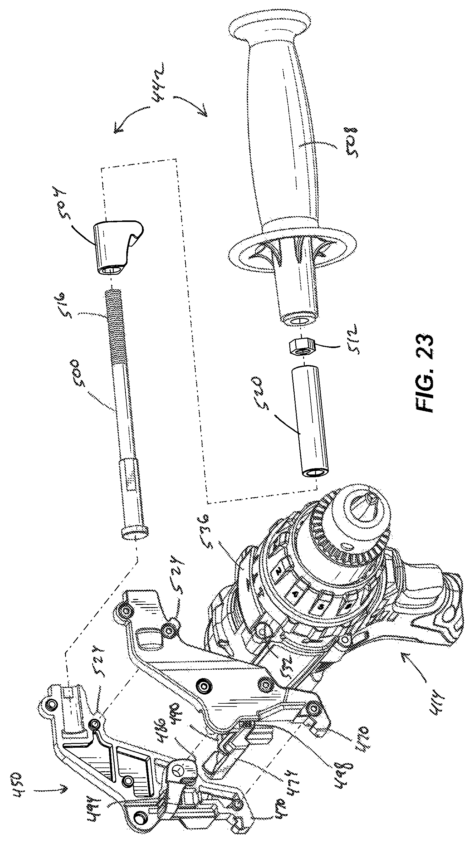
XML
uspto.report is an independent third-party trademark research tool that is not affiliated, endorsed, or sponsored by the United States Patent and Trademark Office (USPTO) or any other governmental organization. The information provided by uspto.report is based on publicly available data at the time of writing and is intended for informational purposes only.
While we strive to provide accurate and up-to-date information, we do not guarantee the accuracy, completeness, reliability, or suitability of the information displayed on this site. The use of this site is at your own risk. Any reliance you place on such information is therefore strictly at your own risk.
All official trademark data, including owner information, should be verified by visiting the official USPTO website at www.uspto.gov. This site is not intended to replace professional legal advice and should not be used as a substitute for consulting with a legal professional who is knowledgeable about trademark law.