System and method for mitigating or preventing eye damage from structured light IR/NIR projector systems
Cohen , et al.
U.S. patent number 10,694,168 [Application Number 16/378,627] was granted by the patent office on 2020-06-23 for system and method for mitigating or preventing eye damage from structured light ir/nir projector systems. This patent grant is currently assigned to Corephotonics Ltd.. The grantee listed for this patent is Corephotonics Ltd.. Invention is credited to Noy Cohen, Ephraim Goldenberg.


| United States Patent | 10,694,168 |
| Cohen , et al. | June 23, 2020 |
System and method for mitigating or preventing eye damage from structured light IR/NIR projector systems
Abstract
Systems and methods for mitigating or preventing eye damage from structured light IR/NIR projector systems. When a SL projector with a multi-light-source array that projects a SL pattern onto an object, a first camera images the light pattern projected on the object and optionally provides camera frames viewed by a user. A multi-light-source array controller is configurable to control separately an on or off status and/or an intensity of each light source in the multi-light-source array, and an algorithm is operative to detect in the first camera frames SL pattern elements projected onto the object, to detect the eyes of the user, to compare a position of each projected SL pattern element with a position of the detected eyes, and to send commands to the multi-light-source array controller to turn off or reduce the intensity of array light sources that are projected or likely to be projected onto the user's eyes.
| Inventors: | Cohen; Noy (Tel Aviv, IL), Goldenberg; Ephraim (Ashdod, IL) | ||||||||||
|---|---|---|---|---|---|---|---|---|---|---|---|
| Applicant: |
|
||||||||||
| Assignee: | Corephotonics Ltd. (Tel Aviv,
IL) |
||||||||||
| Family ID: | 68236716 | ||||||||||
| Appl. No.: | 16/378,627 | ||||||||||
| Filed: | April 9, 2019 |
Prior Publication Data
| Document Identifier | Publication Date | |
|---|---|---|
| US 20190327462 A1 | Oct 24, 2019 | |
Related U.S. Patent Documents
| Application Number | Filing Date | Patent Number | Issue Date | ||
|---|---|---|---|---|---|
| 62661017 | Apr 22, 2018 | ||||
| Current U.S. Class: | 1/1 |
| Current CPC Class: | H04N 13/25 (20180501); H04N 13/254 (20180501); H04N 13/239 (20180501); H04N 5/247 (20130101) |
| Current International Class: | H04N 13/254 (20180101); H04N 13/25 (20180101); H04N 13/239 (20180101) |
References Cited [Referenced By]
U.S. Patent Documents
| 4199785 | April 1980 | McCullough et al. |
| 5005083 | April 1991 | Grage et al. |
| 5032917 | July 1991 | Aschwanden |
| 5041852 | August 1991 | Misawa et al. |
| 5051830 | September 1991 | von Hoessle |
| 5099263 | March 1992 | Matsumoto et al. |
| 5248971 | September 1993 | Mandl |
| 5287093 | February 1994 | Amano et al. |
| 5394520 | February 1995 | Hall |
| 5436660 | July 1995 | Sakamoto |
| 5444478 | August 1995 | Lelong et al. |
| 5459520 | October 1995 | Sasaki |
| 5657402 | August 1997 | Bender et al. |
| 5682198 | October 1997 | Katayama et al. |
| 5768443 | June 1998 | Michael et al. |
| 5926190 | July 1999 | Turkowski et al. |
| 5940641 | August 1999 | McIntyre et al. |
| 5982951 | November 1999 | Katayama et al. |
| 6101334 | August 2000 | Fantone |
| 6128416 | October 2000 | Oura |
| 6148120 | November 2000 | Sussman |
| 6208765 | March 2001 | Bergen |
| 6268611 | July 2001 | Pettersson et al. |
| 6549215 | April 2003 | Jouppi |
| 6611289 | August 2003 | Yu et al. |
| 6643416 | November 2003 | Daniels et al. |
| 6650368 | November 2003 | Doron |
| 6680748 | January 2004 | Monti |
| 6714665 | March 2004 | Hanna et al. |
| 6724421 | April 2004 | Glatt |
| 6738073 | May 2004 | Park et al. |
| 6741250 | May 2004 | Furlan et al. |
| 6750903 | June 2004 | Miyatake et al. |
| 6778207 | August 2004 | Lee et al. |
| 7002583 | February 2006 | Rabb, III |
| 7015954 | March 2006 | Foote et al. |
| 7038716 | May 2006 | Klein et al. |
| 7199348 | April 2007 | Olsen et al. |
| 7206136 | April 2007 | Labaziewicz et al. |
| 7248294 | July 2007 | Slatter |
| 7256944 | August 2007 | Labaziewicz et al. |
| 7305180 | December 2007 | Labaziewicz et al. |
| 7339621 | March 2008 | Fortier |
| 7346217 | March 2008 | Gold, Jr. |
| 7365793 | April 2008 | Cheatle et al. |
| 7411610 | August 2008 | Doyle |
| 7424218 | September 2008 | Baudisch et al. |
| 7509041 | March 2009 | Hosono |
| 7533819 | May 2009 | Barkan et al. |
| 7619683 | November 2009 | Davis |
| 7738016 | June 2010 | Toyofuku |
| 7773121 | August 2010 | Huntsberger et al. |
| 7809256 | October 2010 | Kuroda et al. |
| 7880776 | February 2011 | LeGall et al. |
| 7918398 | April 2011 | Li et al. |
| 7964835 | June 2011 | Olsen et al. |
| 7978239 | July 2011 | Deever et al. |
| 8115825 | February 2012 | Culbert et al. |
| 8149327 | April 2012 | Lin et al. |
| 8154610 | April 2012 | Jo et al. |
| 8238695 | August 2012 | Davey et al. |
| 8274552 | September 2012 | Dahi et al. |
| 8390729 | March 2013 | Long et al. |
| 8391697 | March 2013 | Cho et al. |
| 8400555 | March 2013 | Georgiev et al. |
| 8439265 | May 2013 | Ferren et al. |
| 8446484 | May 2013 | Muukki et al. |
| 8483452 | July 2013 | Ueda et al. |
| 8514491 | August 2013 | Duparre |
| 8547389 | October 2013 | Hoppe et al. |
| 8553106 | October 2013 | Scarff |
| 8587691 | November 2013 | Takane |
| 8619148 | December 2013 | Watts et al. |
| 8803990 | August 2014 | Smith |
| 8896655 | November 2014 | Mauchly et al. |
| 8976255 | March 2015 | Matsuoto et al. |
| 9019387 | April 2015 | Nakano |
| 9025073 | May 2015 | Attar et al. |
| 9025077 | May 2015 | Attar et al. |
| 9041835 | May 2015 | Honda |
| 9137447 | September 2015 | Shibuno |
| 9185291 | November 2015 | Shabtay et al. |
| 9215377 | December 2015 | Sokeila et al. |
| 9215385 | December 2015 | Luo |
| 9270875 | February 2016 | Brisedoux et al. |
| 9286680 | March 2016 | Jiang et al. |
| 9344626 | May 2016 | Silverstein et al. |
| 9360671 | June 2016 | Zhou |
| 9369621 | June 2016 | Malone et al. |
| 9413930 | August 2016 | Geerds |
| 9413984 | August 2016 | Attar et al. |
| 9420180 | August 2016 | Jin |
| 9438792 | September 2016 | Nakada et al. |
| 9485432 | November 2016 | Medasani et al. |
| 9578257 | February 2017 | Attar et al. |
| 9618748 | April 2017 | Munger et al. |
| 9681057 | June 2017 | Attar et al. |
| 9723220 | August 2017 | Sugie |
| 9736365 | August 2017 | Laroia |
| 9736391 | August 2017 | Du et al. |
| 9768310 | September 2017 | Ahn et al. |
| 9800798 | October 2017 | Ravirala et al. |
| 9851803 | December 2017 | Fisher et al. |
| 9894287 | February 2018 | Qian et al. |
| 9900522 | February 2018 | Lu |
| 9927600 | March 2018 | Goldenberg et al. |
| 2002/0005902 | January 2002 | Yuen |
| 2002/0030163 | March 2002 | Zhang |
| 2002/0063711 | May 2002 | Park et al. |
| 2002/0075258 | June 2002 | Park et al. |
| 2002/0122113 | September 2002 | Foote |
| 2002/0167741 | November 2002 | Koiwai et al. |
| 2003/0002109 | January 2003 | Hochberg |
| 2003/0030729 | February 2003 | Prentice et al. |
| 2003/0093805 | May 2003 | Gin |
| 2003/0160886 | August 2003 | Misawa et al. |
| 2003/0202113 | October 2003 | Yoshikawa |
| 2004/0008773 | January 2004 | Itokawa |
| 2004/0012683 | January 2004 | Yamasaki et al. |
| 2004/0017386 | January 2004 | Liu et al. |
| 2004/0027367 | February 2004 | Pilu |
| 2004/0061788 | April 2004 | Bateman |
| 2004/0141086 | July 2004 | Mihara |
| 2004/0240052 | December 2004 | Minefuji et al. |
| 2005/0013509 | January 2005 | Samadani |
| 2005/0046740 | March 2005 | Davis |
| 2005/0157184 | July 2005 | Nakanishi et al. |
| 2005/0168834 | August 2005 | Matsumoto et al. |
| 2005/0200718 | September 2005 | Lee |
| 2006/0054782 | March 2006 | Olsen et al. |
| 2006/0056056 | March 2006 | Ahiska et al. |
| 2006/0102907 | May 2006 | Lee et al. |
| 2006/0125937 | June 2006 | LeGall et al. |
| 2006/0170793 | August 2006 | Pasquarette et al. |
| 2006/0175549 | August 2006 | Miller et al. |
| 2006/0187310 | August 2006 | Janson et al. |
| 2006/0187322 | August 2006 | Janson et al. |
| 2006/0187338 | August 2006 | May et al. |
| 2006/0198405 | September 2006 | Guenter |
| 2007/0024737 | February 2007 | Nakamura et al. |
| 2007/0126911 | June 2007 | Nanjo |
| 2007/0177025 | August 2007 | Kopet et al. |
| 2007/0188653 | August 2007 | Pollock et al. |
| 2007/0189386 | August 2007 | Imagawa et al. |
| 2007/0257184 | November 2007 | Olsen et al. |
| 2007/0285550 | December 2007 | Son |
| 2008/0017557 | January 2008 | Witdouck |
| 2008/0024614 | January 2008 | Li et al. |
| 2008/0025634 | January 2008 | Border et al. |
| 2008/0030592 | February 2008 | Border et al. |
| 2008/0030611 | February 2008 | Jenkins |
| 2008/0084484 | April 2008 | Ochi et al. |
| 2008/0117316 | May 2008 | Orimoto |
| 2008/0218611 | September 2008 | Parulski et al. |
| 2008/0218612 | September 2008 | Border et al. |
| 2008/0218613 | September 2008 | Janson et al. |
| 2008/0219654 | September 2008 | Border et al. |
| 2009/0086074 | April 2009 | Li et al. |
| 2009/0109556 | April 2009 | Shimizu et al. |
| 2009/0122195 | May 2009 | Van Baar et al. |
| 2009/0122406 | May 2009 | Rouvinen et al. |
| 2009/0128644 | May 2009 | Camp et al. |
| 2009/0219547 | September 2009 | Kauhanen et al. |
| 2009/0252484 | October 2009 | Hasuda et al. |
| 2009/0295949 | December 2009 | Ojala |
| 2009/0324135 | December 2009 | Kondo et al. |
| 2010/0013906 | January 2010 | Border et al. |
| 2010/0020221 | January 2010 | Tupman et al. |
| 2010/0060746 | March 2010 | Olsen et al. |
| 2010/0097444 | April 2010 | Lablans |
| 2010/0103194 | April 2010 | Chen et al. |
| 2010/0165131 | July 2010 | Makimoto et al. |
| 2010/0238327 | September 2010 | Griffith et al. |
| 2010/0283842 | November 2010 | Guissin et al. |
| 2010/0321494 | December 2010 | Peterson et al. |
| 2011/0058320 | March 2011 | Kim et al. |
| 2011/0064327 | March 2011 | Dagher et al. |
| 2011/0080487 | April 2011 | Venkataraman et al. |
| 2011/0128288 | June 2011 | Petrou et al. |
| 2011/0164172 | July 2011 | Shintani et al. |
| 2011/0229054 | September 2011 | Weston et al. |
| 2011/0234853 | September 2011 | Hayashi et al. |
| 2011/0234881 | September 2011 | Wakabayashi et al. |
| 2011/0242286 | October 2011 | Pace et al. |
| 2011/0242355 | October 2011 | Goma et al. |
| 2011/0298966 | December 2011 | Kirschstein et al. |
| 2012/0026366 | February 2012 | Golan et al. |
| 2012/0062780 | March 2012 | Morihisa |
| 2012/0069235 | March 2012 | Imai |
| 2012/0075489 | March 2012 | Nishihara |
| 2012/0105579 | May 2012 | Jeon et al. |
| 2012/0154614 | June 2012 | Moriya et al. |
| 2012/0196648 | August 2012 | Havens et al. |
| 2012/0229663 | September 2012 | Nelson et al. |
| 2012/0249815 | October 2012 | Bohn et al. |
| 2012/0287315 | November 2012 | Huang et al. |
| 2012/0320467 | December 2012 | Baik et al. |
| 2013/0002928 | January 2013 | Imai |
| 2013/0016427 | January 2013 | Sugawara |
| 2013/0076922 | March 2013 | Shihoh et al. |
| 2013/0093842 | April 2013 | Yahata |
| 2013/0113894 | May 2013 | Mirlay |
| 2013/0127854 | May 2013 | Shpunt |
| 2013/0135445 | May 2013 | Dahi et al. |
| 2013/0182150 | July 2013 | Asakura |
| 2013/0201360 | August 2013 | Song |
| 2013/0202273 | August 2013 | Ouedraogo et al. |
| 2013/0235224 | September 2013 | Park et al. |
| 2013/0250150 | September 2013 | Malone et al. |
| 2013/0258044 | October 2013 | Betts-LaCroix |
| 2013/0270419 | October 2013 | Singh et al. |
| 2013/0278785 | October 2013 | Nomura et al. |
| 2013/0321668 | December 2013 | Kamath |
| 2014/0009631 | January 2014 | Topliss |
| 2014/0049615 | February 2014 | Uwagawa |
| 2014/0118584 | May 2014 | Lee et al. |
| 2014/0192238 | July 2014 | Attar et al. |
| 2014/0192253 | July 2014 | Laroia |
| 2014/0208856 | July 2014 | Schmid |
| 2014/0218587 | August 2014 | Shah |
| 2014/0313316 | October 2014 | Olsson et al. |
| 2014/0362242 | December 2014 | Takizawa |
| 2015/0002683 | January 2015 | Hu et al. |
| 2015/0042870 | February 2015 | Chan et al. |
| 2015/0070781 | March 2015 | Cheng et al. |
| 2015/0092066 | April 2015 | Geiss et al. |
| 2015/0138381 | May 2015 | Ahn |
| 2015/0154776 | June 2015 | Zhang et al. |
| 2015/0162048 | June 2015 | Hirata et al. |
| 2015/0195458 | July 2015 | Nakayama et al. |
| 2015/0215516 | July 2015 | Dolgin |
| 2015/0237280 | August 2015 | Choi et al. |
| 2015/0242994 | August 2015 | Shen |
| 2015/0253543 | September 2015 | Mercado |
| 2015/0253647 | September 2015 | Mercado |
| 2015/0271471 | September 2015 | Hsieh et al. |
| 2015/0286033 | October 2015 | Osborne |
| 2015/0316744 | November 2015 | Chen |
| 2015/0334309 | November 2015 | Peng et al. |
| 2016/0044250 | February 2016 | Shabtay et al. |
| 2016/0070088 | March 2016 | Koguchi |
| 2016/0154202 | June 2016 | Wippermann et al. |
| 2016/0154204 | June 2016 | Lim et al. |
| 2016/0212358 | July 2016 | Shikata |
| 2016/0241751 | August 2016 | Park |
| 2016/0291295 | October 2016 | Shabtay et al. |
| 2016/0295112 | October 2016 | Georgiev et al. |
| 2016/0301840 | October 2016 | Du et al. |
| 2016/0353008 | December 2016 | Osborne |
| 2016/0353012 | December 2016 | Kao et al. |
| 2017/0019616 | January 2017 | Zhu et al. |
| 2017/0187962 | June 2017 | Lee et al. |
| 2017/0214846 | July 2017 | Du et al. |
| 2017/0214866 | July 2017 | Zhu et al. |
| 2017/0242225 | August 2017 | Fiske |
| 2017/0272638 | September 2017 | Lee |
| 2017/0289458 | October 2017 | Song et al. |
| 2017/0307759 | October 2017 | Pei |
| 2018/0017844 | January 2018 | Yu et al. |
| 2018/0024329 | January 2018 | Goldenberg et al. |
| 2018/0059379 | March 2018 | Chou |
| 2018/0120674 | May 2018 | Avivi et al. |
| 2018/0150973 | May 2018 | Tang et al. |
| 2018/0241922 | August 2018 | Baldwin et al. |
| 2018/0295292 | October 2018 | Lee et al. |
| 2019/0072771 | March 2019 | Hall |
| 2019/0295279 | September 2019 | Wang |
| 2019/0391271 | December 2019 | Goodwill |
| 2020/0012113 | January 2020 | Keller |
| 2020/0028329 | January 2020 | Gronenborn |
| 101276415 | Oct 2008 | CN | |||
| 102739949 | Oct 2012 | CN | |||
| 103024272 | Apr 2013 | CN | |||
| 103841404 | Jun 2014 | CN | |||
| 1536633 | Jun 2005 | EP | |||
| 1780567 | May 2007 | EP | |||
| 2523450 | Nov 2012 | EP | |||
| S59191146 | Oct 1984 | JP | |||
| 04211230 | Aug 1992 | JP | |||
| H07318864 | Dec 1995 | JP | |||
| 08271976 | Oct 1996 | JP | |||
| 2003298920 | Oct 2003 | JP | |||
| 2004133054 | Apr 2004 | JP | |||
| 2004245982 | Sep 2004 | JP | |||
| 2005099265 | Apr 2005 | JP | |||
| 2006238325 | Sep 2006 | JP | |||
| 2007228006 | Sep 2007 | JP | |||
| 2007306282 | Nov 2007 | JP | |||
| 2008076485 | Apr 2008 | JP | |||
| 2011085666 | Apr 2011 | JP | |||
| 2013106289 | May 2013 | JP | |||
| 20090058229 | Jun 2009 | KR | |||
| 20100008936 | Jan 2010 | KR | |||
| 20140014787 | Feb 2014 | KR | |||
| 101477178 | Dec 2014 | KR | |||
| 20150118012 | Oct 2015 | KR | |||
| 2010122841 | Oct 2010 | WO | |||
| 2014072818 | May 2014 | WO | |||
| 2017025822 | Feb 2017 | WO | |||
| 2017037688 | Mar 2017 | WO | |||
| 2018130898 | Jul 2018 | WO | |||
Other References
|
Statistical Modeling and Performance Characterization of a Real-Time Dual Camera Surveillance System, Greienhagen et al., Publisher: IEEE, 2000, 8 pages. cited by applicant . A 3MPixel Multi-Aperture Image Sensor with 0.7.mu.m Pixels in 0.11.mu.m CMOS, Fife et al., Stanford University, 2008, 3 pages. cited by applicant . Dual camera intelligent sensor for high definition 360 degrees surveillance, Scotti et al., Publisher: IET, May 9, 2000, 8 pages. cited by applicant . Dual-sensor foveated imaging system, Hua et al., Publisher: Optical Society of America, Jan. 14, 2008, 11 pages. cited by applicant . Defocus Video Matting, McGuire et al., Publisher: ACM SIGGRAPH, Jul. 31, 2005, 11 pages. cited by applicant . Compact multi-aperture imaging with high angular resolution, Santacana et al., Publisher: Optical Society of America, 2015, 10 pages. cited by applicant . Multi-Aperture Photography, Green et al., Publisher: Mitsubishi Electric Research Laboratories, Inc., Jul. 2007, 10 pages. cited by applicant . Multispectral Bilateral Video Fusion, Bennett et al., Publisher: IEEE, May 2007, 10 pages. cited by applicant . Super-resolution imaging using a camera array, Santacana et al., Publisher: Optical Society of America, 2014, 6 pages. cited by applicant . Optical Splitting Trees for High-Precision Monocular Imaging, McGuire et al., Publisher: IEEE, 2007, 11 pages. cited by applicant . High Performance Imaging Using Large Camera Arrays, Wilburn et al., Publisher: Association for Computing Machinery, Inc., 2005, 12 pages. cited by applicant . Real-time Edge-Aware Image Processing with the Bilateral Grid, Chen et al., Publisher: ACM SIGGRAPH, 2007, 9 pages. cited by applicant . Superimposed multi-resolution imaging, Carles et al., Publisher: Optical Society of America, 2017, 13 pages. cited by applicant . Viewfinder Alignment, Adams et al., Publisher: Eurographics, 2008, 10 pages. cited by applicant . Dual-Camera System for Multi-Level Activity Recognition, Bodor et al., Publisher: IEEE, Oct. 2014, 6 pages. cited by applicant . Engineered to the task: Why camera-phone cameras are different, Giles Humpston, Publisher: Solid State Technology, Jun. 2009, 3 pages. cited by applicant. |
Primary Examiner: Alcon; Fernando
Attorney, Agent or Firm: Nathan & Associates Nathan; Menachem
Parent Case Text
CROSS-REFERENCE TO RELATED APPLICATIONS
This application is related to and claims priority from U.S. Provisional Patent Application No. 62/661,017 filed Apr. 22, 2018, which is expressly incorporated herein by reference in its entirety.
Claims
What is claimed is:
1. A system comprising: a) a structured light (SL) projector having a multi-light-source array that projects a SL pattern onto an object; b) a first camera for imaging the light pattern projected onto the object and, optionally, for imaging the object to provide a first stream of frames; c) a multi-light-source array controller configurable to control separately an on or off status and/or an intensity of each light source in the multi-light-source array; and d) an algorithm operative to detect in the first camera frames SL pattern elements projected onto the object, to detect eyes of a user, to compare a position of each projected SL pattern element with a position of the detected eyes, and to send commands to the multi-light-source array controller to turn off or reduce the intensity of array light sources that are projected or likely to be projected onto the user's eyes.
2. The system of claim 1, further comprising a second camera for imaging the object, wherein the second camera provides a second stream of frames used to detect the eyes of the user.
3. The system of claim 1, wherein the algorithm is further operative to turn on or to increase the intensity of light sources that are not projected onto the eyes.
4. The system of claim 1, wherein the multi-light-source array is a VCSEL array comprising a plurality of VCSELs and wherein the multi-light-source array controller is a VCSEL array controller.
5. The system of claim 2, wherein the algorithm is further operative to turn on or to increase the intensity of light sources that are not projected onto the eyes of the user.
6. The system of claim 2, where the multi-light-source array is a VCSEL array comprising a plurality of VCSELs and wherein the multi-light-source array controller is a VCSEL array controller.
7. The system of claim 1, wherein the SL projector is a near infrared (NIR) SL projector and wherein the first camera is a NIR camera.
8. The system of claim 2, wherein the second camera is a RGB camera.
9. The system of claim 6, wherein the second camera is a RGB camera.
10. The system of claim 1, included in a mobile electronic device.
11. The system of claim 10, wherein the mobile electronic device is a smart-phone.
12. The system of claim 7, included in a mobile electronic device.
13. The system of claim 12, wherein the mobile electronic device is a smart-phone.
14. A method, comprising: a) using a structured light (SL) projector having a multi-light-source array to project a SL pattern onto an object; b) using a first camera for imaging the light pattern projected on the object and optionally, for imaging the object to provide first camera frames c) configuring a multi-light-source array controller to control separately an on or off status and/or an intensity of each light source in the multi-light-source array; d) detecting in the first camera frames SL pattern elements projected onto the object and detecting eyes of a user; e) comparing a position of each detected SL pattern element with a position of the detected eyes; and f) sending commands to the multi-light-source array controller to turn off or reduce the intensity of array light sources that are projected or likely to be projected onto the eyes of the user.
15. The method of claim 14, further comprising using a second camera for imaging the object, wherein the second camera provides a second stream of frames used to detect the eyes of the user.
Description
FIELD
Embodiments disclosed herein relate in general to near infra-red (NIR) structured light projection and imaging systems which are aimed at faces.
BACKGROUND
Recently, mobile devices such as cell-phones (and in particular smart-phones) have started to incorporate a front-facing projection-and-imaging system that is used for applications such as face identification and face tracking. Often, such systems are based on a structured light (SL) projector that may operate in the near-infra-red (NIR) range and which projects a pattern onto a user's face. Structured light is a process of known pattern projection (e.g. dots or lines) onto an object or scene. Pattern imaging with a camera (e.g. a dedicated and pre-calibrated camera) allows depth calculation of the object or the scene.
In this disclosure, NIR refers to the wavelength range of 780 nm-1120 nm, which is invisible to the human eye. A NIR-sensitive camera images the face with the pattern projected on it. A processor can then calculate depth from the relative position of pattern elements projected on the face. This depth information is then used for many applications, like 3D modeling of the face, security face identification (such as unlocking the mobile device, authorizing payments, etc.), augmented reality applications, camera effects (such as bokeh), avatar animation, etc.
In some cases, the SL projector component comprises an array of vertical cavity surface emitting laser (VCSEL) elements that are replicated using a diffractive optical element (DOE) (e.g. a Dammann diffraction grating) and then imaged onto a scene. Each VCSEL creates a separate dot of NIR light. The spatial arrangement of the VCSELs in the array and the replicating DOE determines how the dots are imaged onto the scene.
Projecting a pattern in the NIR range on a user's face can potentially be harmful to the eyes. The retina is sensitive to light in the NIR range. Research has shown that prolonged exposure to it, beyond a certain intensity threshold, may cause damage to the retina in the form of IR cataracts and flash burns due to a rise in temperature. Therefore, eye safety regulations normally limit the intensity and duration of SL pattern projection (see, e.g. regulation IEC/EN 62471 and others).
It is therefore beneficial to have a front-facing structured light system that can minimize or eliminate projection of NIR light onto the eyes and increase. Such a system can also increase the light intensity provided by a SL projector while keeping eye safety regulations.
SUMMARY
Embodiments disclosed herein relate to a system and method that significantly reduce the exposure of mobile device users' eyes to potentially harmful NIR light emitted from SL projectors embedded in the device. This is done by locating and tracking the user's eyes in camera frames, registering them to the position of imaged VCSELs and controlling the intensity of VCSELs in the VCSEL array so that no VCSEL is imaged onto the user's eyes.
In exemplary embodiments, there are provided systems comprising a SL projector having a multi-light-source array that projects a SL pattern onto an object, a first camera for imaging the light pattern projected on the object and, optionally, for imaging the object to provide first camera frames, a multi-light-source array controller configurable to control separately an on or off status and/or an intensity of each light source in the multi-light-source array, and an algorithm operative to detect in the first camera frames SL pattern elements projected onto the object, to detect a user's eyes, to compare a position of each projected SL pattern element with a position of the detected eyes, and to send commands to the multi-light-source array controller to turn off or reduce the intensity of array light sources that are projected or likely to be projected onto the user's eyes.
In an exemplary embodiment, a system further comprises a second camera for imaging the object, wherein the second camera provides a second stream of frames.
In an exemplary embodiment, the algorithm is further operative to turn on or to increase the intensity of light sources that are not projected onto the user's eyes.
In an exemplary embodiment, the multi-light-source array is a VCSEL array comprising a plurality of VCSELs and the multi-light-source array controller is a VCSEL array controller.
In an exemplary embodiment, the SL projector is a NIR SL projector and the first camera is a NIR camera.
In an exemplary embodiment, the second camera is a RGB camera.
In an exemplary embodiment, a system as above or below is included in a mobile electronic device.
In an exemplary embodiment, the mobile electronic device is a smart-phone.
In exemplary embodiments, there are provided methods, comprising: using a SL projector having a multi-light-source array to project a SL pattern onto an object, using a first camera for imaging the light pattern projected on the object and optionally, for imaging the object to provide first camera frames, configuring a multi-light-source array controller to control separately an on or off status and/or an intensity of each light source in the multi-light-source array, detecting in the first camera frames SL pattern elements projected onto the object and detecting a user's eyes, comparing a position of each detected SL pattern element with a position of the detected eyes, and sending commands to the multi-light-source array controller to turn off or reduce the intensity of array light sources that are projected or likely to be projected onto the user's eyes.
BRIEF DESCRIPTION OF THE DRAWINGS
Non-limiting examples of embodiments disclosed herein are described below with reference to figures attached hereto that are listed following this paragraph. Identical structures, elements or parts that appear in more than one figure are generally labeled with a same numeral in all the figures in which they appear. The drawings and descriptions are meant to illuminate and clarify embodiments disclosed herein and should not be considered limiting in any way:
FIG. 1 shows a block diagram of the system according to aspects of presently disclosed subject matter;
FIG. 2A shows schematically the system of FIG. 1 incorporated in a smart-phone, with the projector projecting a pattern onto a user's face including eyes;
FIG. 2B shows the same features as FIG. 2A, except that pixels of the projected patterns are removed from the user's eyes;
FIG. 3 illustrates in a flow chart a method according to aspects of presently disclosed subject matter.
DETAILED DESCRIPTION
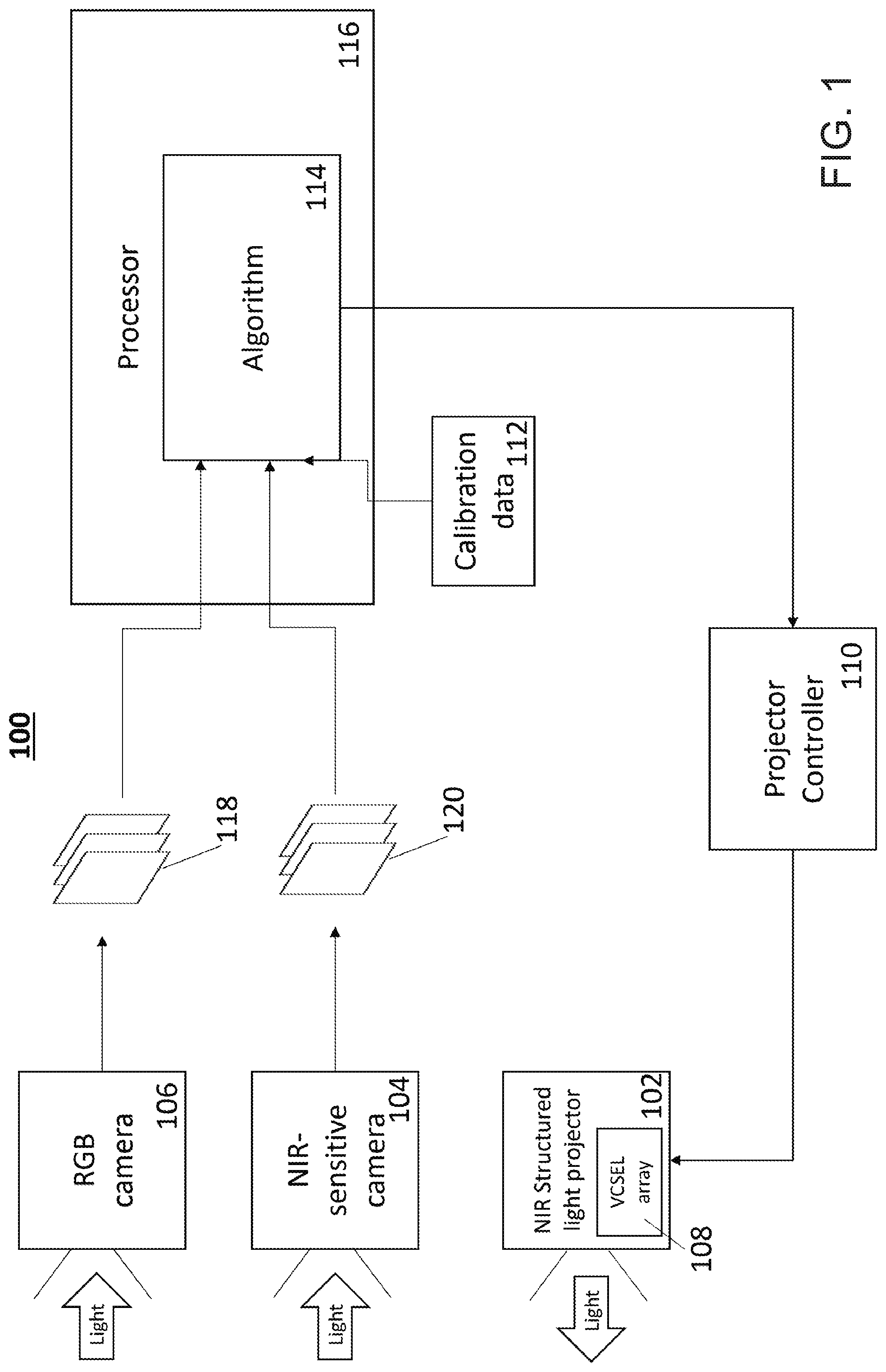
FIG. 1 shows a block diagram of the system according to aspects of presently disclosed subject matter and numbered 100. System 100 that comprises a NIR structured light projector 102 (referred herein simply as a projector), for example a projector based on a VCSEL array 108 with independently addressable elements, an NIR-sensitive camera 104 and a red-green-blue (RGB) camera 106 (e.g. a color camera used for imaging an object on a sensor). Projector 102 may include other light source arrays (and thus be referred to as a "multi-light-source" array) with individually addressable and controlled light source elements, for example an array of micro light-emitting-diodes (micro LEDs). Hereafter, the description continues with specific reference to a VCSEL array, with the understanding that the proposed system and methods apply to a SL projector with other arrays of independently controlled light sources.
In an embodiment, RGB camera 106 and NIR-sensitive camera 104 are a single camera that is sensitive to visible light and also to NIR light.
System 100 further includes a VCSEL array controller (or "projector controller") 110, implemented in hardware (HW) or software (SW). VCSEL array controller 110 can control VCSEL array 108 and turn on, turn off, or modify the intensity of each VCSEL element (or simply "VCSEL"), separately and independently of the other VCSELs, based on input signals. In other words, each VCSEL is individually addressable and controllable by controller 110.
System 100 further includes calibration data 112 for calibrating NIR-sensitive camera 104, RGB camera 106 and projector 102. Calibration data 112 may be used to align the fields of view (FOVs) of the two cameras and of the projector and to compensate for parallax, tilts, assembly tolerances, etc. In some cases, calibration data 112 may be calculated and stored in system 100 during an assembly process. In some cases, calibration data 112 may be adaptively calculated and stored in system 100 during its usage.
System 100 further includes an algorithm 114 that can be implemented in HW or in SW, (for example by configuring a processor 116 to run it). Algorithm 114 is responsible for determining VCSELs of the array to be turned on or off or to have their intensity modified. The algorithm detects and tracks the position of the eyes of the user looking at the device and controls VCSEL array 108 in a way that VCSEL illumination on the eyes is decreased and/or turned off. The algorithm evaluates continuously images from RGB camera 106 and/or NIR-sensitive camera 104 and sends continuously commands to VCSEL array controller 110 to turn-off or reduce the intensity of VCSELs that may be imaged onto the eyes of the user, and to turn-on or increase the intensity of VCSELs that are no longer imaged onto the eyes and therefore do not pose a threat to cause damage.
In an embodiment, processor 116 may be included in system 100 and algorithm 114 may be implemented in SW. In an embodiment, VCSEL array controller 110 may be implemented in SW on the processor. In another embodiment, VCSEL array controller 110 and/or algorithm 114 may be implemented in dedicated HW.
System 100 may be included or incorporated in, for example, a mobile electronics device such as a smart-phone, a tablet computer, a laptop computer, etc. FIGS. 2A and 2B show schematically system 100 incorporated in a smart-phone 200 having a smart-phone display 206. Projector 102, NIR-sensitive camera 104 and RGB camera 106 are front-facing, i.e. are facing a user face 202 with eyes 204 when smart-phone 200 faces the user. Projector 102 and cameras 104 and 106 may be arranged to share substantially the same FOV (e.g. more than 80% or 90% or 95% of the FOV of each element is shared with other elements) for a range of distances, for example in a range between ca. 10-100 cm from the cameras.
In use, projector 102 projects a pattern onto an object or scene. For example, in FIGS. 2A and 2B, projector 102 projects a pattern having pattern dots (points) onto user face 202 and eyes 204. In FIG. 2A, the pattern consists of evenly spread points. This is just a non-limiting example of one possible pattern. Other patterns may be used, in particular a semi-random pattern. The systems and methods described herein may be used in a similar manner regardless of the projected pattern. The pattern dots in eyes 204 are marked in FIG. 2A as 208a-208f. RGB camera 106 collects visible light and produces a stream of RGB frames 118. NIR-sensitive camera 104 collects NIR light and produces a stream of NIR frames 120, which may include the pattern produced by projector 102. RGB frames 118, NIR frames 120 and calibration data 112 are input to algorithm 114. Algorithm 114 calculates which VCSELs in VCSEL array 108 should modify their intensity based on frames 118 and 120 and calibration data 112 and produces a set of commands to VCSEL array controller 110. VCSEL array controller 110 controls VCSEL array 108 according to the commands, which in turn affect the SL pattern projected onto the scene.
In an use embodiment, algorithm 114 may analyze the input frames 118 from the RGB camera 106 and/or input frames 120 from NIR-sensitive camera 104, detects the position of the eyes (e.g. eyes 204) in the image using known techniques (such as image processing, computer vision or machine learning), estimates the distance from projector 102 to eyes 204 of user 202, for example, by measuring the distance between eyes 204 in frames 118 or 120, or by measuring the size of the face in the image, and inferring the distance of user 202 to system 100; uses the position of the eyes in the image, the estimated user distance and calibration data 112 between projector 102, RGB camera 106 and NIR-sensitive camera 104 to determine the VCSELs that may be imaged onto the subject's eyes (for example, in FIG. 2A, VCSELs imaged as dots 208a-208f); and sends commands to VCSEL array controller 110 to turn off or reduce the intensity of the specific VCSELs (perhaps, keeping some safety margins around the eyes), and to turn back on or increase the intensity back to standard levels of VCSELs that are not imaged onto the subject's eyes. In addition, algorithm 114 updates related applications that use VCSEL array 108 data about the modification to the VCSELs' intensity.
Specifically, in an example shown in FIG. 2B, the commands to VCSEL, array controller 110 is to turn off the VCSELs projecting dots 208a-208f, such that these dots are removed from the pattern seen in FIG. 2B. In other cases the command may be to reduce the intensity of the dots projected to the eyes.
In an use embodiment, when VCSEL array 108 becomes active, algorithm 114 finds the position of the eyes in RGB camera 106 using computer vision techniques, and registers the relevant sections in the image from RGB camera 106 to the image from NIR-sensitive camera 104 that images the pattern projected by projector 102. The registration can make use of calibration data 112. After the registration process, algorithm 114 finds which VCSELs in VCSEL array 108 are imaged onto the user's eyes by looking for projected pattern elements imaged by NIR-sensitive camera 104 that are in the region of the eyes.
In an use embodiment, algorithm 114 continues to track the position and distance of the eyes over time in a stream of RGB frames 118 and/or NIR frames 120, also by making use of projected pattern data or depth map (if such is available) and calibration data, and continuously updates VCSEL array 108, turning back on or increasing back the intensity of VCSELs that do not cover the eyes and turning off or reducing the intensity of VCSELs that cover them.
In an use embodiment, algorithm 114 uses the image data from NIR-sensitive camera 104 to detect whether any VCSELs are imaged onto the user's eyes, by extracting the eyes position using computer vision techniques and checking whether any VCSEL is imaged onto them by looking for projected pattern elements imaged by NIR-sensitive camera 104 at the region of the eyes. Algorithm 114 continuously tracks the position of the eyes and updates VCSEL array 108 through VCSEL array controller 110 accordingly.
In an use embodiment, algorithm 114 analyzes the image of NIR-sensitive camera 104 and/or RGB camera 106 after VCSEL array 108 has been turned on (without any modification of VCSELs intensity from operation without the algorithm improvement suggested herein), detects the region where the eyes are located, registers the image from RGB camera 106 to the image from NIR-sensitive camera 104, and finds whether any VCSELs illuminate the eyes.
When VCSEL array controller 110 turns off some of the VCSELs in VCSEL array 108 that are imaged into the eyes of user 202, the projected pattern coverage of the field of view is compromised, not only in the area of the eyes but also in other areas, since the image of VCSEL array 108 is replicated many times in order to cover a large FOV, for example between 40 degrees diagonal and 80 degrees diagonal. There could be between several such replications (for example, 4-5) to thousands of them (for example 2000). The data from VICSELs that have been turned off may be interpolated using VCSELs that are imaged to nearby positions in the FOV.
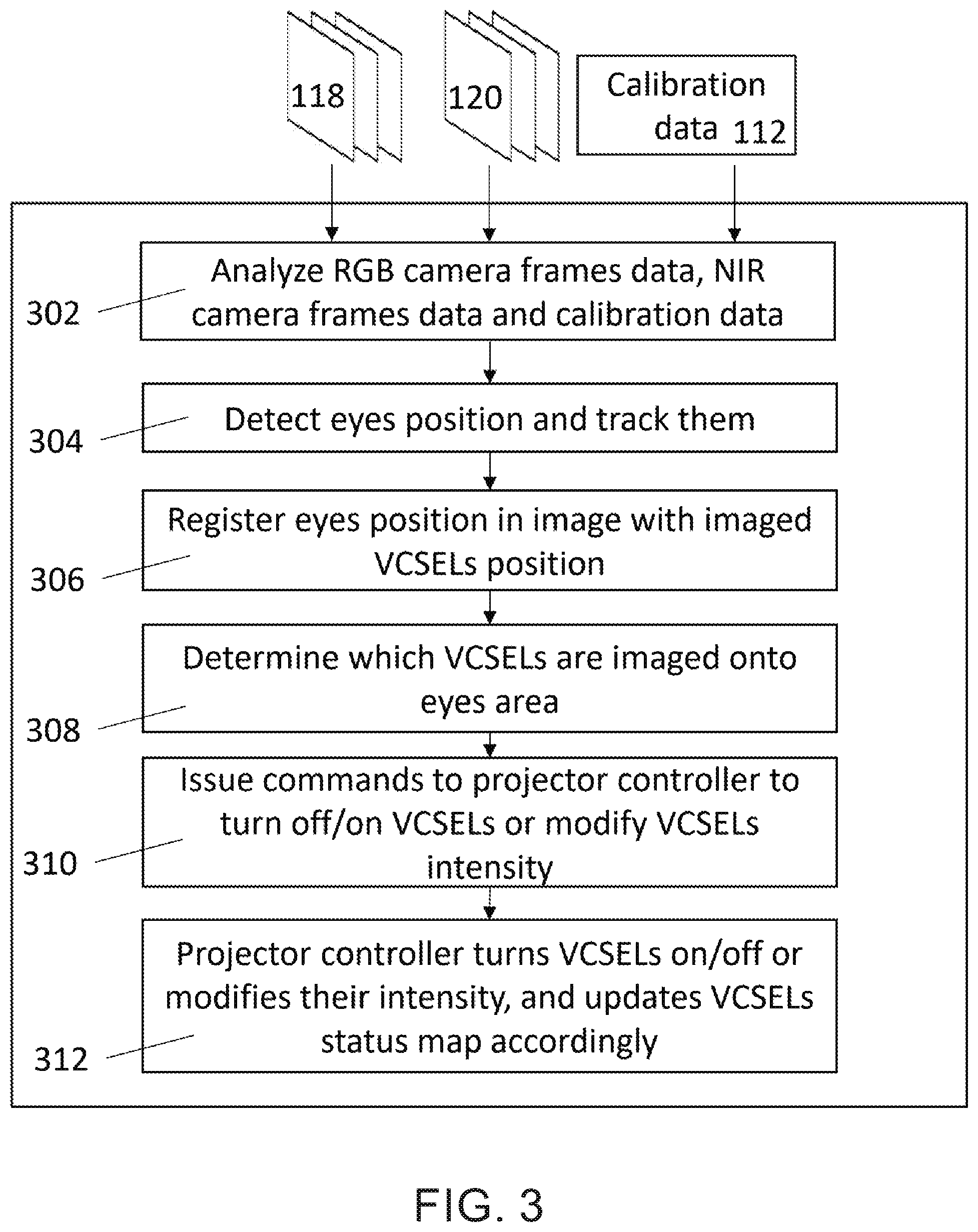
FIG. 3 depicts in a flow chart an exemplary embodiment of the operation of system 100. In step 302, an analysis of frames from RGB camera 106 and frames from NIR-sensitive camera 104 is performed, also using calibration data 112. In step 304, eyes position is detected in these frames, and the position is tracked across frames in time. In step 306, the eyes position is registered and compared to imaged VCSELs positions. In step 308, it is determined which VCSELs cover the eyes area, if any. In step 310, commands are issued to VCSEL array controller 110 to turn off or reduce intensity of VCSELs that cover the eyes area and to turn back on or increase back intensity of VCSELs that do not cover the eyes area. In step 312, the controller executes the commands. In addition, in step 312, an updated expected VCSELs map is generated, considering the VCSELs that have been modified. This map can be used in various algorithms and system components that rely on the VCSEL data to perform various tasks. This series of steps runs continuously, on the stream of frames. The processing can be executed on a per-frame basis, or every number of frames.
The result of the proposed system and method is a significant reduction in exposure of the user eyes to NIR illumination from the structured light projector. In some cases, such a method may allow increasing the total power emitted from the SL projector while satisfying eye safety regulations, as the users eye is projected with none or less light that the case without using the proposed method.
While this disclosure has been described in terms of certain embodiments and generally associated methods, alterations and permutations of the embodiments and methods will be apparent to those skilled in the art. For example, while the disclosure refers to a front-facing structured light NIR projector, it applies also to a back-facing structured light NIR projector that can be used in conjunction with back-facing cameras in a mobile device. For example, while a system and method disclosed herein refers specifically to mobile devices, a similar system and method may be used/applied in non-mobile devices. The disclosure is to be understood as not is limited by the specific embodiments described herein.
It is emphasized that citation or identification of any reference in this application shall not be construed as an admission that such a reference is available or admitted as prior art.
* * * * *
D00000
D00001
D00002
D00003
XML
uspto.report is an independent third-party trademark research tool that is not affiliated, endorsed, or sponsored by the United States Patent and Trademark Office (USPTO) or any other governmental organization. The information provided by uspto.report is based on publicly available data at the time of writing and is intended for informational purposes only.
While we strive to provide accurate and up-to-date information, we do not guarantee the accuracy, completeness, reliability, or suitability of the information displayed on this site. The use of this site is at your own risk. Any reliance you place on such information is therefore strictly at your own risk.
All official trademark data, including owner information, should be verified by visiting the official USPTO website at www.uspto.gov. This site is not intended to replace professional legal advice and should not be used as a substitute for consulting with a legal professional who is knowledgeable about trademark law.