Multi-wire permuted forward error correction
Shokrollahi , et al.
U.S. patent number 10,693,587 [Application Number 16/031,877] was granted by the patent office on 2020-06-23 for multi-wire permuted forward error correction. This patent grant is currently assigned to KANDOU LABS, S.A.. The grantee listed for this patent is Kandou Labs, S.A.. Invention is credited to Ali Hormati, Amin Shokrollahi.


View All Diagrams
| United States Patent | 10,693,587 |
| Shokrollahi , et al. | June 23, 2020 |
Multi-wire permuted forward error correction
Abstract
Methods and systems are described for obtaining a plurality of information bits, and responsively partitioning the obtained plurality of information bits into a plurality of subsets of information bits, generating a plurality of streams of forward error correction (FEC)-encoded bits using a plurality of FEC encoders receiving respective subsets of the plurality of subsets of information bits, providing the plurality of streams of FEC-encoded bits to a plurality of sub-channel encoders, each sub-channel encoder receiving a respective stream of FEC-encoded bits from a different FEC encoder of the plurality of FEC encoders for generating a set of codewords of a vector signaling code, and wherein sequential streams of FEC-encoded bits from a given FEC encoder are provided to different sub-channel encoders for each successively generated set of codewords, and transmitting the successively generated sets of codewords of the vector signaling code over a multi-wire bus.
| Inventors: | Shokrollahi; Amin (Preverenges, CH), Hormati; Ali (Ecublens, CH) | ||||||||||
|---|---|---|---|---|---|---|---|---|---|---|---|
| Applicant: |
|
||||||||||
| Assignee: | KANDOU LABS, S.A. (Lausanne,
CH) |
||||||||||
| Family ID: | 64902925 | ||||||||||
| Appl. No.: | 16/031,877 | ||||||||||
| Filed: | July 10, 2018 |
Prior Publication Data
| Document Identifier | Publication Date | |
|---|---|---|
| US 20190013899 A1 | Jan 10, 2019 | |
Related U.S. Patent Documents
| Application Number | Filing Date | Patent Number | Issue Date | ||
|---|---|---|---|---|---|
| 62530809 | Jul 10, 2017 | ||||
| Current U.S. Class: | 1/1 |
| Current CPC Class: | H04J 13/004 (20130101); H03M 13/6561 (20130101); H03M 13/1515 (20130101); H03M 13/05 (20130101); H03M 13/3761 (20130101); H03M 13/27 (20130101); H04L 25/0272 (20130101); H04L 25/085 (20130101); H04L 1/0041 (20130101); H04L 1/0071 (20130101) |
| Current International Class: | H03M 13/00 (20060101); H04L 1/00 (20060101); H03M 13/15 (20060101); H03M 13/27 (20060101); H04L 25/02 (20060101); H03M 13/05 (20060101); H03M 13/37 (20060101); H04J 13/00 (20110101); H04L 25/08 (20060101) |
References Cited [Referenced By]
U.S. Patent Documents
| 3196351 | July 1965 | David |
| 3965418 | June 1976 | Bauer et al. |
| 3970795 | July 1976 | Allen |
| 4112264 | September 1978 | Abramson et al. |
| 4163258 | July 1979 | Ebihara et al. |
| 4486739 | December 1984 | Franaszek et al. |
| 4499550 | February 1985 | Ray et al. |
| 4772845 | September 1988 | Scott |
| 4864303 | September 1989 | Ofek |
| 5053974 | October 1991 | Penz |
| 5166956 | November 1992 | Baltus et al. |
| 5168509 | December 1992 | Nakamura et al. |
| 5311516 | May 1994 | Kuznicki et al. |
| 5331320 | July 1994 | Cideciyan et al. |
| 5412689 | May 1995 | Chan et al. |
| 5449895 | September 1995 | Hecht et al. |
| 5553097 | September 1996 | Dagher |
| 5566193 | October 1996 | Cloonan |
| 5825808 | October 1998 | Hershey et al. |
| 5856935 | January 1999 | Moy et al. |
| 5875202 | February 1999 | Venters et al. |
| 5881130 | March 1999 | Zhang |
| 5982954 | November 1999 | Delen et al. |
| 6005895 | December 1999 | Perino et al. |
| 6084883 | July 2000 | Norrell et al. |
| 6084958 | July 2000 | Blossom |
| 6097732 | August 2000 | Jung |
| 6119263 | September 2000 | Mowbray et al. |
| 6128330 | October 2000 | Schilling |
| 6154498 | November 2000 | Dabral et al. |
| 6175230 | January 2001 | Hamblin et al. |
| 6188497 | February 2001 | Franck et al. |
| 6226330 | May 2001 | Mansur |
| 6278740 | August 2001 | Nordyke |
| 6317465 | November 2001 | Akamatsu et al. |
| 6359931 | March 2002 | Perino et al. |
| 6404820 | June 2002 | Postol |
| 6452420 | September 2002 | Wong |
| 6473877 | October 2002 | Sharma |
| 6483828 | November 2002 | Balachandran et al. |
| 6504875 | January 2003 | Perino et al. |
| 6556628 | April 2003 | Poulton et al. |
| 6621427 | September 2003 | Greenstreet |
| 6621945 | September 2003 | Bissessur |
| 6650638 | November 2003 | Walker et al. |
| 6661355 | December 2003 | Cornelius et al. |
| 6690739 | February 2004 | Mui |
| 6766342 | July 2004 | Kechriotis |
| 6865234 | March 2005 | Agazzi |
| 6865236 | March 2005 | Terry |
| 6876317 | April 2005 | Sankaran |
| 6898724 | May 2005 | Chang |
| 6954492 | October 2005 | Williams |
| 6963622 | November 2005 | Eroz et al. |
| 6973613 | December 2005 | Cypher |
| 6976194 | December 2005 | Cypher |
| 6982954 | January 2006 | Dhong et al. |
| 6990138 | January 2006 | Bejjani et al. |
| 6999516 | February 2006 | Rajan |
| 7023817 | April 2006 | Kuffner et al. |
| 7039136 | May 2006 | Olson et al. |
| 7075996 | July 2006 | Simon et al. |
| 7080288 | July 2006 | Ferraiolo et al. |
| 7082557 | July 2006 | Schauer et al. |
| 7127003 | October 2006 | Rajan et al. |
| 7142612 | November 2006 | Horowitz et al. |
| 7167523 | January 2007 | Mansur |
| 7180949 | February 2007 | Kleveland et al. |
| 7184483 | February 2007 | Rajan |
| 7231558 | June 2007 | Gentieu et al. |
| 7269130 | September 2007 | Pitio |
| 7269212 | September 2007 | Chau et al. |
| 7335976 | February 2008 | Chen et al. |
| 7346819 | March 2008 | Bansal et al. |
| 7356213 | April 2008 | Cunningham et al. |
| 7358869 | April 2008 | Chiarulli et al. |
| 7362130 | April 2008 | Broyde et al. |
| 7362697 | April 2008 | Becker et al. |
| 7370264 | May 2008 | Worley et al. |
| 7633850 | December 2009 | Ahn |
| 7643588 | January 2010 | Visalli et al. |
| 7656321 | February 2010 | Wang |
| 7694204 | April 2010 | Schmidt et al. |
| 7698088 | April 2010 | Sul et al. |
| 7706456 | April 2010 | Laroia et al. |
| 7734191 | June 2010 | Welch |
| 7746764 | June 2010 | Rawlins et al. |
| 7868790 | January 2011 | Bae |
| 7869546 | January 2011 | Tsai |
| 7882413 | February 2011 | Chen et al. |
| 7899653 | March 2011 | Hollis |
| 7933770 | April 2011 | Krueger et al. |
| 8050332 | November 2011 | Chung et al. |
| 8055095 | November 2011 | Palotai et al. |
| 8091006 | January 2012 | Prasad et al. |
| 8149906 | April 2012 | Saito et al. |
| 8159375 | April 2012 | Abbasfar |
| 8159376 | April 2012 | Abbasfar |
| 8185807 | May 2012 | Oh et al. |
| 8199849 | June 2012 | Oh et al. |
| 8199863 | June 2012 | Chen et al. |
| 8209580 | June 2012 | Varnica et al. |
| 8218670 | July 2012 | Abou |
| 8233544 | July 2012 | Bao et al. |
| 8238318 | August 2012 | Negus |
| 8245094 | August 2012 | Jiang et al. |
| 8245102 | August 2012 | Cory et al. |
| 8279094 | October 2012 | Abbasfar |
| 8279745 | October 2012 | Dent |
| 8279976 | October 2012 | Lin et al. |
| 8284848 | October 2012 | Nam et al. |
| 8289914 | October 2012 | Li et al. |
| 8295250 | October 2012 | Gorokhov et al. |
| 8338318 | December 2012 | Siebers |
| 8341492 | December 2012 | Shen et al. |
| 8365035 | January 2013 | Hara |
| 8429492 | April 2013 | Yoon et al. |
| 8429495 | April 2013 | Przybylski |
| 8462891 | June 2013 | Kizer et al. |
| 8472513 | June 2013 | Malipatil et al. |
| 8498368 | July 2013 | Rusted et al. |
| 8520493 | August 2013 | Goulahsen |
| 8521020 | August 2013 | Welch |
| 8539318 | September 2013 | Shokrollahi et al. |
| 8577284 | November 2013 | Seo et al. |
| 8578246 | November 2013 | Mittelholzer et al. |
| 8588254 | November 2013 | Diab et al. |
| 8588280 | November 2013 | Oh et al. |
| 8593305 | November 2013 | Tajalli et al. |
| 8620166 | December 2013 | Guha |
| 8644497 | February 2014 | Clausen et al. |
| 8649445 | February 2014 | Cronie et al. |
| 8687968 | April 2014 | Nosaka et al. |
| 8711919 | April 2014 | Kumar |
| 8718184 | May 2014 | Cronie et al. |
| 8755426 | June 2014 | Cronie et al. |
| 8773964 | July 2014 | Hsueh et al. |
| 8780687 | July 2014 | Clausen et al. |
| 8792594 | July 2014 | Vojcic |
| 8831440 | September 2014 | Yu et al. |
| 8879660 | November 2014 | Peng et al. |
| 8938171 | January 2015 | Tang et al. |
| 8949693 | February 2015 | Ordentlich et al. |
| 8989317 | March 2015 | Holden et al. |
| 8996740 | March 2015 | Wiley et al. |
| 9015566 | April 2015 | Cronie et al. |
| 9071476 | June 2015 | Fox et al. |
| 9077386 | July 2015 | Holden et al. |
| 9100232 | August 2015 | Hormati et al. |
| 9152495 | October 2015 | Losh et al. |
| 9172412 | October 2015 | Kim et al. |
| 9183085 | November 2015 | Northcott |
| 9197470 | November 2015 | Okunev |
| 9246713 | January 2016 | Shokrollahi |
| 9251873 | February 2016 | Fox et al. |
| 9288082 | March 2016 | Ulrich et al. |
| 9288089 | March 2016 | Cronie et al. |
| 9331962 | May 2016 | Lida et al. |
| 9362974 | June 2016 | Fox et al. |
| 9363114 | June 2016 | Shokrollahi et al. |
| 9401828 | July 2016 | Cronie et al. |
| 9432082 | August 2016 | Ulrich et al. |
| 9444654 | September 2016 | Hormati et al. |
| 9455744 | September 2016 | George et al. |
| 9461862 | October 2016 | Holden et al. |
| 9479369 | October 2016 | Shokrollahi |
| 9509437 | November 2016 | Shokrollahi |
| 9537644 | January 2017 | Jones et al. |
| 9634797 | April 2017 | Benammar et al. |
| 9667379 | May 2017 | Cronie |
| 9710412 | July 2017 | Sengoku |
| 9852806 | December 2017 | Stauffer et al. |
| 10055372 | August 2018 | Shokrollahi |
| 2001/0006538 | July 2001 | Simon et al. |
| 2002/0044316 | April 2002 | Myers |
| 2002/0152340 | October 2002 | Dreps et al. |
| 2002/0154633 | October 2002 | Shin et al. |
| 2002/0163881 | November 2002 | Dhong et al. |
| 2002/0174373 | November 2002 | Chang |
| 2002/0181607 | December 2002 | Izumi |
| 2003/0016770 | January 2003 | Trans et al. |
| 2003/0086366 | May 2003 | Branlund et al. |
| 2003/0185310 | October 2003 | Ketchum et al. |
| 2004/0057525 | March 2004 | Rajan et al. |
| 2004/0146117 | July 2004 | Subramaniam et al. |
| 2004/0155802 | August 2004 | Lamy et al. |
| 2004/0161019 | August 2004 | Raghavan et al. |
| 2004/0239374 | December 2004 | Hori |
| 2005/0213686 | September 2005 | Love et al. |
| 2006/0013331 | January 2006 | Choi et al. |
| 2006/0080087 | April 2006 | Vandali |
| 2006/0126751 | June 2006 | Bessios |
| 2006/0159005 | July 2006 | Rawlins et al. |
| 2006/0291571 | December 2006 | Divsalar et al. |
| 2006/0291589 | December 2006 | Eliezer et al. |
| 2007/0030796 | February 2007 | Green |
| 2007/0076871 | April 2007 | Renes |
| 2007/0204205 | August 2007 | Niu et al. |
| 2007/0283210 | December 2007 | Prasad et al. |
| 2008/0016432 | January 2008 | Lablans |
| 2008/0104374 | May 2008 | Mohamed |
| 2008/0192621 | August 2008 | Suehiro |
| 2008/0316070 | December 2008 | Van et al. |
| 2009/0046009 | February 2009 | Fujii |
| 2009/0059782 | March 2009 | Cole |
| 2009/0141827 | June 2009 | Saito et al. |
| 2009/0150754 | June 2009 | Dohmen et al. |
| 2009/0154604 | June 2009 | Lee et al. |
| 2009/0316730 | December 2009 | Feng et al. |
| 2010/0046644 | February 2010 | Mazet |
| 2010/0054355 | March 2010 | Kinjo et al. |
| 2010/0081451 | April 2010 | Mueck et al. |
| 2010/0215112 | August 2010 | Tsai et al. |
| 2010/0235673 | September 2010 | Abbasfar |
| 2010/0296556 | November 2010 | Rave et al. |
| 2010/0309964 | December 2010 | Oh et al. |
| 2011/0014865 | January 2011 | Seo et al. |
| 2011/0051854 | March 2011 | Kizer et al. |
| 2011/0072330 | March 2011 | Kolze |
| 2011/0235501 | September 2011 | Goulahsen |
| 2011/0268225 | November 2011 | Cronie et al. |
| 2011/0286497 | November 2011 | Nervig |
| 2011/0299555 | December 2011 | Cronie et al. |
| 2011/0302478 | December 2011 | Cronie et al. |
| 2012/0036415 | February 2012 | Shafrir et al. |
| 2012/0213299 | August 2012 | Cronie et al. |
| 2013/0010892 | January 2013 | Cronie et al. |
| 2013/0013870 | January 2013 | Cronie et al. |
| 2013/0114392 | May 2013 | Sun et al. |
| 2013/0259113 | October 2013 | Kumar |
| 2013/0315501 | November 2013 | Atanassov et al. |
| 2013/0346830 | December 2013 | Ordentlich et al. |
| 2014/0068385 | March 2014 | Zhang |
| 2014/0068391 | March 2014 | Goel et al. |
| 2014/0112376 | April 2014 | Wang |
| 2014/0177645 | June 2014 | Cronie et al. |
| 2014/0254642 | September 2014 | Fox et al. |
| 2015/0070201 | March 2015 | Dedic et al. |
| 2015/0078479 | March 2015 | Whitby-Strevens |
| 2015/0092532 | April 2015 | Shokrollahi et al. |
| 2015/0222458 | August 2015 | Hormati et al. |
| 2015/0236885 | August 2015 | Ling et al. |
| 2015/0249559 | September 2015 | Shokrollahi et al. |
| 2015/0333940 | November 2015 | Shokrollahi |
| 2015/0349835 | December 2015 | Fox et al. |
| 2015/0365263 | December 2015 | Zhang et al. |
| 2015/0380087 | December 2015 | Mittelholzer et al. |
| 2015/0381768 | December 2015 | Fox et al. |
| 2016/0020796 | January 2016 | Hormati et al. |
| 2016/0020824 | January 2016 | Ulrich et al. |
| 2016/0036616 | February 2016 | Holden et al. |
| 2016/0218894 | July 2016 | Fox et al. |
| 2016/0380787 | December 2016 | Hormati et al. |
| 2017/0272285 | September 2017 | Shokrollahi et al. |
| 2019/0103903 | April 2019 | Yang |
| 1671092 | Sep 2005 | CN | |||
| 1864346 | Nov 2006 | CN | |||
| 101854223 | Oct 2010 | CN | |||
| 101820288 | Jan 2013 | CN | |||
| 1926267 | May 2008 | EP | |||
| 2003163612 | Jun 2003 | JP | |||
| 2005002162 | Jan 2005 | WO | |||
| 2009084121 | Jul 2009 | WO | |||
| 2010031824 | Mar 2010 | WO | |||
Other References
|
Abbasfar, Aliazam , "Generalized Differential Vector Signaling", IEEE International Conference on Communications, ICC '09, Jun. 14, 2009, 1-5 (5 pages). cited by applicant . Anonymous , "Constant-weight code", Wikipedia.org, retrieved on Feb. 6, 2017, (3 pages). cited by applicant . Ben-Neticha, Zouhair , et al., "The "Stretched"-Golay and Other Codes for High-SNR Finite-Delay Quantization of the Gaussian Source at 1/2 Bit Per Sample", IEEE Transactions on Communications, New York, US, vol. 38, No. 12, XP000203339, Dec. 1990, 2089-2093 (5 pages). cited by applicant . Burr, A.G. , "Spherical Codes for M-ARY Code Shift Keying", Second IEE National Conference on Telecommunications, University of York, UK, Apr. 2, 1989, 67-72 (6 pages). cited by applicant . Counts, Lew , et al., "One-Chip "Slide Rule" Works with Logs, Antilogs for Real-Time Processing", Analog Devices, Computational Products 6, Reprinted from Electronic Design, May 2, 1985, 3-9 (7 pages). cited by applicant . Dasilva, Victor , et al., "Multicarrier Orthogonal CDMA Signals for Quasi-Synchronous Communication Systems", IEEE Journal on Selected Areas in Communications, vol. 12, No. 5, Jun. 1994, 842-852 (11 pages). cited by applicant . Ericson, Thomas , et al., "Spherical Codes Generated by Binary Partitions of Symmetric Pointsets", IEEE Transactions on Information Theory, vol. 41, No. 1, Jan. 1995, 107-129 (23 pages). cited by applicant . Farzan, Kamran , et al., "Coding Schemes for Chip-to-Chip Interconnect Applications", IEEE Transactions on Very Large Scale Integration (VLSI) Systems, vol. 14, No. 4, Apr. 2006, 393-406 (14 pages). cited by applicant . Giovaneli, Carlos Lopez, et al., "Space-Frequency Coded OFDM System for Multi-Wire Power Line Communications", Power Line Communications and Its Applications, 2005 International Symposium on Vancouver, BC, Canada, IEEE XP-002433844, Apr. 6-8, 2005, 191-195 (5 pages). cited by applicant . Healey, Adam , et al., "A Comparison of 25 Gbps NRZ & PAM-4 Modulation used in Legacy & Premium Backplane Channels", Tyco Electronics Corporation, DesignCon 2012, Jan. 2012, 1-16 (16 pages). cited by applicant . Holden, Brian , "An exploration of the technical feasibility of the major technology options for 400GE backplanes", IEEE 802.3 400GE Study Group, Geneva, CH, Jul. 16, 2013, 1-18 (18 pages). cited by applicant . Holden, Brian , "Simulation results for NRZ, ENRZ & PAM-4 on 16-wire full-sized 400GE backplanes", IEEE 802.3 400E Study Group, York, UK, Sep. 2, 2013, 1-19 (19 pages). cited by applicant . Holden, Brian , "Using Ensemble NRZ Coding for 400GE Electrical Interfaces", IEEE 802.3 400GE Study Group, May 17, 2013, 1-24 (24 pages). cited by applicant . Jiang, Anxiao , et al., "Rank Modulation for Flash Memories", IEEE Transactions of Information Theory, vol. 55, No. 6, Jun. 2009, 2659-2673 (16 pages). cited by applicant . Oh, Dan , et al., "Pseudo-Differential Vector Signaling for Noise Reduction in Single-Ended Signaling Systems", DesignCon 2009, Rambus Inc., Jan. 2009, (22 pages). cited by applicant . Poulton, John , "Multiwire Differential Signaling", UNC-CH Department of Computer Science Version 1.1, Aug. 5, 2003, 1-20 (20 pages). cited by applicant . She, James , et al., "A Framework of Cross-Layer Superposition Coded Multicast for Robust IPTV Services over WiMAX", IEEE Wireless Communications and Networking Conference, Apr. 15, 2008, 3139-3144 (6 pages). cited by applicant . Skliar, Osvaldo , et al., "A Method for the Analysis of Signals: the Square-Wave Method", Revista de Matematica: Teoria y Aplicationes, vol. 15, No. 2, Mar. 2008, 109-129 (21 pages). cited by applicant . Slepian, David , "Permutation Modulation", Proceedings of the IEE, vol. 53, No. 3, Mar. 1965, 228-236 (9 pages). cited by applicant . Wang, Xin , et al., "Applying CDMA Technique to Network-on-Chip", IEEE Transactions on Very Large Scale Integration (VLSI) Systems, vol. 15, No. 10, Oct. 1, 2007, 1091-1100 (10 pages). cited by applicant. |
Primary Examiner: Abraham; Esaw T
Attorney, Agent or Firm: Invention Mine LLC
Parent Case Text
CROSS-REFERENCE TO RELATED APPLICATIONS
This application claims the benefit of U.S. Provisional Application No. 62/530,809, filed Jul. 10, 2017, naming Amin Shokrollahi and Ali Hormati, entitled "Multi-Wire Permuted Forward Error Correction", which is hereby incorporated herein by reference in its entirety for all purposes.
REFERENCES
The following prior applications are herein incorporated by reference in their entirety for all purposes:
U.S. Pat. No. 9,288,089 of application Ser. No. 12/784,414, filed May 20, 2010, naming Harm Cronie and Amin Shokrollahi, entitled "Orthogonal Differential Vector Signaling" (hereinafter "Cronie I").
U.S. patent application Ser. No. 13/154,009, filed Jun. 5, 2011, naming Harm Cronie and Amin Shokrollahi, entitled "Error Control Coding for Orthogonal Differential Vector Signaling" (hereinafter "Cronie II").
U.S. patent application Ser. No. 14/253,584, filed Apr. 15, 2014, naming John Fox, Brian Holden, Ali Hormati, Peter Hunt, John D Keay, Amin Shokrollahi, Anant Singh, Andrew Kevin John Stewart, Giuseppe Surace, and Roger Ulrich, entitled "Methods and Systems for High Bandwidth Communications Interface" (hereinafter called "Fox I")
U.S. Pat. No. 8,296,632 of application Ser. No. 12/479,605, filed Jun. 5, 2009, naming Amin Shokrollahi, entitled "Encoding and decoding of generalized Reed-Solomon codes using parallel processing techniques" (hereinafter "Shokrollahi I").
U.S. patent application Ser. No. 14/612,241, filed Aug. 4, 2015, naming Amin Shokrollahi, Ali Hormati, and Roger Ulrich, entitled "Method and Apparatus for Low Power Chip-to-Chip Communications with Constrained ISI Ratio", hereinafter identified as [Shokrollahi II].
U.S. Provisional Patent Application No. 62/485,677, filed Apr. 14, 2017, naming Amin Shokrollahi and Dario Carnelli, entitled "Pipelined Forward Error Correction for Vector Signaling Code Channel", hereinafter identified as [Shokrollahi III].
Claims
The invention claimed is:
1. An apparatus comprising: a plurality of forward error-correction (FEC) encoders configured to generate a plurality of streams of FEC-encoded bits, each FEC encoder configured to receive a respective subset of a plurality of subsets of information bits, and to responsively generate a corresponding stream of FEC-encoded bits of the plurality of streams of FEC-encoded bits; and a permuter configured to receive the plurality of streams of FEC-encoded bits, and to responsively provide each stream of FEC-encoded bits of the plurality of streams of FEC-encoded bits to a respective sub-channel encoder of a plurality of sub-channel encoders, wherein the permuter is configured to provide sequential streams of FEC-encoded bits received from a given FEC encoder in a cyclically varying order to each sub-channel encoder of the plurality of sub-channel encoders; and the plurality of sub-channel encoders configured to generate a set of codewords of a vector signaling code for transmission over a multi-wire bus, each codeword of the set of codewords generated by summing a plurality of weighted sub-channel vectors, each weighted sub-channel vector generated by a respective sub-channel encoder modulating a corresponding sub-channel vector of a plurality of mutually orthogonal sub-channel vectors according to a bit in the received stream of FEC-encoded bits.
2. The apparatus of claim 1, wherein each stream of FEC encoded bits corresponds to a multi-bit packet.
3. The apparatus of claim 1, wherein each stream of FEC encoded bits corresponds to a single bit.
4. The apparatus of claim 1, wherein the permuter comprises a plurality of multiplexors, each multiplexor associated with a corresponding sub-channel encoder and configured to receive all of the streams of FEC encoded bits and to selectively provide the stream of FEC encoded bits to the respective sub-channel encoder.
5. The apparatus of claim 1, wherein the permuter comprises a plurality of de-multiplexors, each de-multiplexor associated with a corresponding FEC encoder and configured to receive a corresponding stream of FEC encoded bits from the corresponding FEC encoder and to selectively provide the received stream of FEC encoded bits to the respective sub-channel encoder.
6. The apparatus of claim 1, wherein the permuter comprises a plurality of buffers configured to buffer the plurality of streams of FEC encoded bits prior to providing the plurality of streams of FEC encoded bits to the plurality of sub-channel encoders.
7. The apparatus of claim 1, wherein the sub-channel encoders are ENRZ sub-channel encoders.
8. The apparatus of claim 1, wherein the permuter further comprises a counter configured to provide a plurality of count signals staggered in time, the staggered count signals used for sequentially providing sequential streams of FEC-encoded bits to each sub-channel encoder in the cyclically varying order.
9. The apparatus of claim 1, wherein each stream of FEC encoded bits is integrated prior to being provided to the respective sub-channel encoder.
10. A method comprising: obtaining a plurality of information bits, and responsively partitioning the obtained plurality of information bits into a plurality of subsets of information bits; generating a plurality of streams of forward error correction (FEC)-encoded bits using a plurality of FEC encoders receiving respective subsets of the plurality of subsets of information bits; providing each stream of FEC-encoded bits of the plurality of streams of FEC-encoded bits to a respective sub-channel encoder of a plurality of sub-channel encoders, wherein sequential streams of FEC-encoded bits from a given FEC encoder are provided in a cyclically varying order to each sub-channel encoder of the plurality of sub-channel encoders; generating a set of codewords of a vector signaling code, each codeword of the set of codewords generated by summing a plurality of weighted sub-channel vectors, each weighted sub-channel vector generated by a respective sub-channel encoder modulating a corresponding sub-channel vector of a plurality of mutually orthogonal sub-channel vectors according to a bit in the received stream of FEC-encoded bits; and transmitting the set of codewords of the vector signaling code over a multi-wire bus.
11. The method of claim 10, wherein each stream of FEC encoded bits corresponds to a multi-bit packet.
12. The method of claim 10, wherein each stream of FEC encoded bits corresponds to a single bit.
13. The method of claim 10, wherein providing each stream of FEC-encoded bits comprises selectively providing the stream of FEC encoded bits to the respective sub-channel encoder using a corresponding multiplexor of a plurality of multiplexors, each multiplexor receiving all of the streams of FEC encoded bits and associated with a corresponding sub-channel encoder.
14. The method of claim 10, wherein providing each stream of FEC-encoded bits comprises selectively providing the received stream of FEC encoded bits to the respective sub-channel encoder via a de-multiplexor of a plurality of de-multiplexors, each de-multiplexor associated with a corresponding FEC encoder.
15. The method of claim 10, further comprising buffering the plurality of streams of FEC encoded bits prior to providing the plurality of streams of FEC encoded bits to the plurality of sub-channel encoders.
16. The method of claim 10, wherein the sub-channel encoders are ENRZ sub-channel encoders.
17. The method of claim 10, wherein sequential streams of FEC-encoded bits are provided to corresponding sub-channel encoders in the cyclically varying order according to respective count signals of a plurality of count signals, the plurality of count signals being staggered in time.
18. The method of claim 10, wherein each stream of FEC encoded bits is integrated prior to being provided to the respective sub-channel encoder.
Description
FIELD OF THE INVENTION
The present embodiments relate to communications systems circuits generally, and more particularly to reduction of communication errors over a high-speed multi-wire interface used for chip-to-chip communication.
BACKGROUND
In modern digital systems, digital information has to be processed in a reliable and efficient way. In this context, digital information is to be understood as information available in discrete, i.e., discontinuous values. Bits, collection of bits, but also numbers from a finite set can be used to represent digital information.
In most chip-to-chip, or device-to-device communication systems, communication takes place over a plurality of wires to increase the aggregate bandwidth. A single or pair of these wires may be referred to as a channel or link and multiple channels create a communication bus between the electronic components. At the physical circuitry level, in chip-to-chip communication systems, buses are typically made of electrical conductors in the package between chips and motherboards, on printed circuit boards ("PCBs") boards or in cables and connectors between PCBs. In high frequency applications, microstrip or stripline PCB traces may be used.
Common methods for transmitting signals over bus wires include single-ended and differential signaling methods. In applications requiring high speed communications, those methods can be further optimized in terms of power consumption and pin-efficiency, especially in high-speed communications. More recently, vector signaling methods have been proposed to further optimize the trade-offs between power consumption, pin efficiency and noise robustness of chip-to-chip communication systems. In those vector signaling systems, digital information at the transmitter is transformed into a different representation space in the form of a vector codeword that is chosen in order to optimize the power consumption, pin-efficiency and speed trade-offs based on the transmission channel properties and communication system design constraints. Herein, this process is referred to as "encoding". The encoded codeword is communicated as a group of signals from the transmitter to one or more receivers. At a receiver, the received signals corresponding to the codeword are transformed back into the original digital information representation space. Herein, this process is referred to as "decoding".
BRIEF DESCRIPTION
In conventional bit-serial communications systems, data words provided by a transmitting or source process are serialized into a sequential stream of bits, in one exemplary embodiment using a digital shift register. At the receiver, sequentially detected bits are deserialized using comparable means, so that a receiving or destination process may be presented with complete data words equivalent to those provided at the transmitter. Vector signaling code communication systems perform comparable operations, although in these embodiments the serialization process generally breaks words into symbol groups (e.g. into five bit elements for a CNRZ-5 system,) and the equivalent deserialization process assembles received groups (of five bits, continuing the same example,) into words again.
Forward Error Correction (FEC) methods have been developed which introduce redundancy into such transmitted data streams as part of a check code that both detects and facilitates correction of errors. The order in which data and redundancy information are structured into a transmitted data stream can significantly impact overall communication latency, especially if multiple essentially parallel communications channels are involved. Solutions are described utilizing interleaving to optimize both burst error control and latency.
Embodiments are described for permuting the transmission order of FEC encoded packets from multiple encoding streams such that sequential packets from each stream are not transmitted sequentially on the same sub-channel nor simultaneously on another sub-channel of a multi sub-channel vector signaling code sent over a multi-wire bus.
Methods and systems are described for obtaining a plurality of information bits, and responsively partitioning the obtained plurality of information bits into a plurality of subsets of information bits, generating a plurality of streams of forward error correction (FEC)-encoded bits using a plurality of FEC encoders receiving respective subsets of the plurality of subsets of information bits, providing the plurality of streams of FEC-encoded bits to a plurality of sub-channel encoders, each sub-channel encoder receiving a respective stream of FEC-encoded bits from a different FEC encoder of the plurality of FEC encoders for generating a set of codewords of a vector signaling code, and wherein sequential streams of FEC-encoded bits from a given FEC encoder are provided to different sub-channel encoders for each successively generated set of codewords, and transmitting the successively generated sets of codewords of the vector signaling code over a multi-wire bus.
BRIEF DESCRIPTION OF FIGURES
FIG. 1 is a block diagram of a system that may serve as the physical transport for the described embodiments, with transmitter 110 communicating over a multiwire 125 communications channel 120 to receiver 130.
FIG. 2 is a more detailed block diagram of Transmitter 110 of FIG. 1.
FIG. 3 is a more detailed block diagram of Receiver 130 of FIG. 1.
FIG. 4 is a block diagram of an embodiment of an error corrected system, where lower-level transport and PHY 430 may be the systems of FIGS. 1-3.
FIG. 5A illustrates operation of Digital Integrator 420 of FIG. 4, and FIG. 5B illustrates operation of the Digital Differentiator function 440 of FIG. 4.
FIG. 6 is a block diagram showing the Distribution of incoming data bytes to multiple FEC Encoders, with the resulting output streams being acted upon by a permuter function prior to transport.
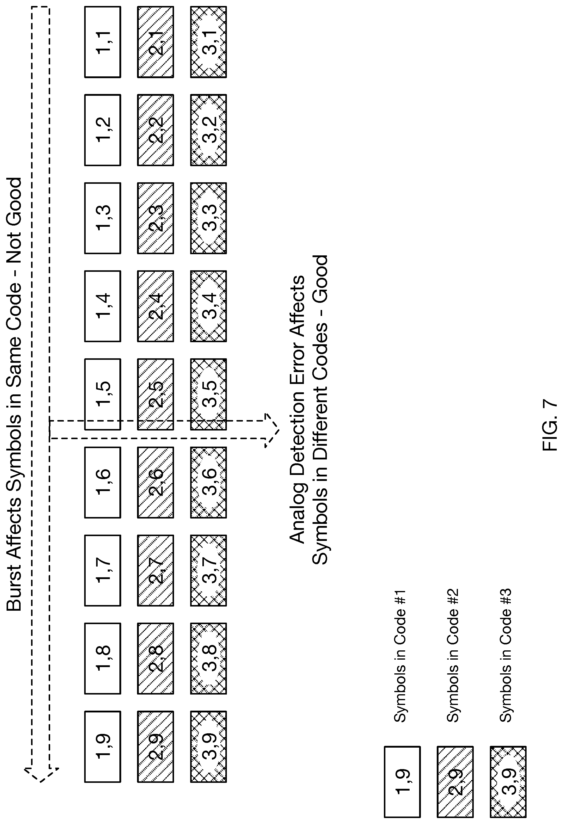
FIG. 7 illustrates three FEC protected data streams passed directly to three transport sub-channels, without permutation.
FIG. 8 illustrates three FEC protected data streams mapped in reoccurring order to three transport sub-channels.
FIG. 9 illustrates three FEC protected data streams mapped in a cyclically varying order to three transport sub-channels.
FIG. 10 shows one embodiment of a permuter subsystem.
FIG. 11 shows another embodiment of a permuter subsystem.
FIG. 12 is a flowchart of a method, in accordance with some embodiments.
DETAILED DESCRIPTION
As described in [Cronie I], [Cronie II], and [Shokrollahi II], vector signaling codes may be used to produce extremely high bandwidth data communications links, such as between two integrated circuit devices in a system. As illustrated by the embodiment of FIG. 1, a data communications channel 120 comprised of multiple wires 125 carries symbols of the vector signaling code, acting together to communicate codewords of the vector signaling code. Depending on the particular vector signaling code used, the number of wires making up a communications link or multi-wire bus may range from two to eight or more, and may also communicate one or more clock signals on separate wires or as sub-channel components of the vector signaling code. In the example of FIG. 1, communication link 120 is illustrated as being composed of eight wires 125, collectively communicating five data values 100 and one clock 105 between transmitter 110 and receiver 130. Further descriptions of such communications links are provided in [Shokrollahi II].
Individual symbols, e.g. transmissions on any single wire, may utilize multiple signal levels, often three or more. Operation at channel rates exceeding 10 Gbps may further complicate receive behavior by requiring deeply pipelined or parallelized signal processing. Embodiments described herein can also be applied to prior art permutation sorting methods not covered by the vector processing methods of [Shokrollahi II]. More generally, embodiments may apply to any communication or storage methods utilizing coordination of multiple channels or elements of the channel to produce a coherent aggregate result.
Because of its characteristic of transmitting multiple symbols essentially in parallel, vector signaling codes are generally considered as communicating data in symbol groups, for example in five-bit increments for the CNRZ-5 code of [Shokrollahi II], or in three-bit increments for the H4 code of [Shokrollahi I], also described in [Fox I] as the Enhanced Non-Return to Zero or ENRZ code. High-bandwidth systems may utilize multiple vector signaling code channels, distributing data across the multiple channels for transmission, and gathering received data from the multiple channels to be transparently combined again at the receiver. Thus, this document may subsequently describe transport as occurring in increments of K*n bits, where n is that code's symbol group or payload size. That reference additionally notes, however, that the encoded sub-channels transporting individual bits are mathematically distinct, and in certain embodiments may be treated as independent transport channels.
Serialization and Deserialization
In conventional bit-serial communications systems, data words provided by a transmitting or source process are serialized into a sequential stream of bits, in one exemplary embodiment using a digital shift register. At the receiver, sequentially detected bits are deserialized using comparable means, so that a receiving or destination process may be presented with complete data words equivalent to those provided at the transmitter. Vector signaling code communication systems perform comparable operations, although in these embodiments the serialization process generally breaks words into symbol groups (e.g. into five bit elements for a CNRZ-5 system,) and the equivalent deserialization process assembles received groups (of five bits, continuing the same example,) into words again.
As is readily apparent, serialization and deserialization introduce latency into the communication channel, with the amount of latency dependent on the number of transmitted elements into which a given data word is serialized, as the entire word is not available until its last-transmitted element has been received and the received word fully reassembled.
In some high-speed communications systems, serialization and deserialization may additionally incorporate multiple processing phases operating essentially in parallel, to provide additional processing time within each phase and/or to permit processing operation using a lower clock rate to reduce power consumption. In one representative embodiment, data words presented by the transmission or source process are broken into symbol groups, with consecutive symbol groups being assigned to sequentially chosen processing phases which perform the necessary encoding, formatting, etc. As each processing phase completes its operations, the processed results are transferred to an output driver for transmission over the communications medium. Thus, in the case where four processing phases are used, each phase will have approximately four transmit unit intervals of time to perform the necessary operations. Similar multiphase processing may occur at the receiver; consecutively received symbol groups being detected by sequentially assigned processing phases and reassembled into output words.
Embodiments incorporating multiple processing phases are used herein as descriptive examples, so as to provide the broadest and most complete illustration of features and behaviors. Other embodiments may utilize fewer or more processing phases, including a single instance, and may incorporate greater or lesser amount of transmit and/or receive processing into the essentially parallel processing phases, with no limitation implied by these examples.
Link Error Correction
Communications system designs emphasize error-free transport of data, despite the inevitable presence of noise and other signal disruptions. Error probabilities over the communications path are expressed as a Bit Error Rate (BER), representing the ratio of bit errors received to overall bits transmitted.
Solutions to detect bit errors, including cyclic check codes, parity, and redundant transmission, are known in the art. Similarly, solutions are known for correction of errors, most notably the closed-loop retransmission methods of the TCP/IP protocol suite, in which a receiver detects an error, uses a return channel to request a retransmission by the transmitter, and then transparently inserts the corrected data into its output stream.
Forward Error Correction
Where use of a return channel is impossible or the round-trip latency of waiting for a retransmission is unacceptable, Forward Error Correction (FEC) methods have been developed which introduce redundancy into the transmitted data stream as part of a check code that both detects and facilitates correction of errors. The more redundancy introduced into the transmitted data stream (e.g. by use of a longer FEC sequence,) the greater the ability of the FEC to correct bit errors, but also the greater the protocol overhead, presenting itself as a lower effective data transmission rate.
In cases where the native communications link has relatively low uncorrected BER (e.g., 1.times.10.sup.-9 to 1.times.10.sup.-10 and the target BER is of the order of 1.times.10.sup.-15 to 1.times.10.sup.-20, other solutions can be found with much lower latency. This is the case, as one example, for the low latency FEC of [Shokrollahi III], targeted for in-package die-to-die links that use vector signaling code such as the Glasswing or CNRZ-5 code of [Shokrollahi II].
Example Embodiment
For purposes of explanation and without implying limitation, the reference system for the following descriptions is assumed to have the following characteristics: Underlying transport providing three sub-channels using ENRZ coding at a 25 Gigasymbol/second rate, equivalent to a 40 picosecond unit interval. Uncorrected BER in the range of 10E-8 to 10E-9, comprised of both random bit and short burst errors Corrected FER or BER less than 10E-19 FEC latency of 80 ns or less.
FIG. 1 is a block diagram of a system that may serve as the physical transport for such a system, with transmitter 110 communicating over a multiwire 125 communications channel 120 to receiver 130.
FIG. 2 illustrates a more detailed block diagram of transmitter 110. In a practical embodiment operating at the example speeds, data will typically be provided using a fairly wide-word interface, to allow a slower transfer rate, with Data Buffer 210 providing the necessary temporary storage and data funneling to the ENRZ sub-channels, which typically transports one bit per unit interval per sub-channel. Multiple data processing phases 220 may be utilized, as are typically used in such high-speed systems. Data Buffer 210 thus reformats Transmit Data into appropriate width for each of the processing phases, but may also distribute data among multiple processing phases to enable parallel computation. Data is encoded 220 and output to Wire outputs W0-W3 by Line Drivers 240 under control of Clock Generator 250. If multiple parallel processing phases are used, multiplexers 230 combine the multiple encoded streams into a single high speed result 235.
FIG. 3 provides a more detailed block diagram of receiver 130. Signals received over Wire inputs W0-W3 are amplified and frequency compensated by Continuous Time Linear Equalizers (CTLE) 310. ENRZ sub-channels are decoded by Multi-input Comparators (MICs) 320, producing three sub-channel results MIC0-MIC2. Clock Recovery subsystem 390 synthesizes a receive clock from data transitions on received sub-channels MIC0-MIC2. As with the example transmitter, multiple receive processing phases 330 will typically be used to facilitate high speed operation, each such phase sampling the received data using the recovered clock. Buffer 370 allows high speed data received from 330 to be reformatted from the typical one received bit per sub-channel per unit interval, into the wider words and slower transfer rates needed to interface to an external system. In some embodiments such as described in [Shokrollahi III], this buffer also provides temporary storage while Error Correction 360 corrects any detected data errors.
FIG. 4 is a high-level block diagram of the error corrected system, showing the ENRZ transport 430 of FIGS. 1-3 as its lower-level or PHY medium. For descriptive purposes, data is described as passing through this system as streams of bytes, although other embodiments may operate at a different granularity; as previously described, the underlying ENRZ transport typically transmits or receives one bit per sub-channel per unit interval, thus an intrinsic serialization/deserialization is assumed to be part of the PHY embodiment.
As used herein, the definition of Digital Integrator 420 is as shown as FIG. 5A, and the definition of Digital Differentiator 440 is as shown as FIG. 5B. These functions are used to control the impact of burst errors, with each burst becoming two bit errors after digital differentiation. The descriptive examples presume these functions perform bitwise operations on a data stream, although known art embodiments operating, as one example on streams of bytes are well known thus no limitation is implied.
Without implying limitation, the Forward Error Correcting algorithm assumed in the following descriptions is a Generalized Reed-Solomon code over the Galois Field GF (256), of length 255, capable of 5-error correcting with a 3.92% redundancy. Another embodiment providing 4-error correcting with 3.14% redundancy is functionally equivalent. Both examples are compatible with the interleaving patterns subsequently described.
Addressing Channel Error Characteristics
Modeling the underlying transport system for error sources, two distinct error modes become apparent. A generalized fault condition or noise source can impact the entire ENRZ transport, introducing codeword errors that lead to essentially simultaneous errors on all sub-channels. Or, more subtly, noise, attenuation, or skew on a subset of the wires may lead to one sub-channel having a substantially higher error rate than the others.
These risks may be mitigated by running separate instances of the FEC algorithm on each of the three ENRZ sub-channels, thus allowing error correction to occur independently. As described in [Fox I], the three sub-channels of the ENRZ code may correspond to mutually orthogonal sub-channel vectors corresponding to rows of an orthogonal matrix. Each row of the orthogonal matrix may be weighted by a respective input bit from e.g., one of the FEC-encoded streams, and all weighted sub-channel vectors may be summed to provide a codeword of the ENRZ vector signaling code. As shown in FIG. 6, a Distributor function distributes or "deals out" incoming data to the individual FEC encoders for transport over the three sub-channels of the ENRZ PHY. In one embodiment, this Distribution is performed on data bytes; other embodiments may perform this distribution at a different granularity. In some embodiments, distributing the streams of FEC-encoded bits as bytes may generate successive sets of codewords, where each successive set of codewords is generated by providing sequential streams of FEC-encoded bits from a given FEC encoder to different sub-channel encoders. Alternatively, if the streams of FEC-encoded bits are distributed of bits, each successive codeword may be generated by providing sequential FEC-encoded bits from a given FEC encoder to different sub-channel encoders.
How this "dealing out" is performed has a significant impact on error containment. An obvious sequential ordering (i.e. allowing parallel streams of data to be transmitted on the three sub-channels) is equivalent to an embodiment having a fall-through or "no op" behavior of the Permuter function of FIG. 6. Such a sequence is shown in FIG. 7, where each sub-channel of the ENRZ code carries a respective stream of FEC-encoded data from a respective FEC encoder. Even with this simple sequential byte ordering within each sub-channel, potential errors in PHY analog detection (as may be caused by generalized faults) affects symbols in different sub-channels (e.g. in different FEC streams), which is a recoverable error. However, persistent weaknesses leading to burst errors in a single sub-channel may affect consecutive symbols in the same FEC-encoded stream, potentially overwhelming the sequential error correction ability of that sub-channel's FEC. Moreover, the sequential transmission of the relatively long FEC blocks leads to increased data latency, as the receiver cannot release a given data block until all of its contents have been received and its error detection values validated.
A second embodiment modifies the Permuter function of FIG. 6 to subdivide a given FEC-encoded stream of incoming bytes into groups of three bytes, which are then dealt out consistently in a "1, 2, 3" order to the three ENRZ sub-channels by simultaneously providing all three bytes to respective sub-channel encoders. As shown in FIG. 8, such a consistent interleaving significantly reduces the perceived data latency and provides increased robustness against burst errors in a single sub-channel. However, as consecutive bytes are now transmitted concurrently in the three sub-channels, there may be a potential for errors in analog detection affecting three symbols in the same code, leading to uncorrectable errors.
In at least one embodiment, the Permuter function of FIG. 6 cyclically permutes the order in which each group of e.g., three bytes is dealt out. As shown in FIG. 9, which byte of the three bytes is the first to be dealt out differs in each three-byte set of the three FEC-encoded streams. Such a permutation protects against both burst errors within a single sub-channel, and burst errors occurring across all sub-channels, while preserving the desirable latency reduction of the previous embodiment.
Permuter Embodiments
FIG. 10 is a block diagram illustrating one implementation of the permuter shown in FIG. 6. As shown, the permuter includes a plurality of buffers configured to store streams of FEC-encoded bits from a respective FEC encoder of the plurality of FEC encoders. Each buffer may receive the stream of FEC-encoded bits pre-serialized from the FEC encoders, or may alternatively perform a serialization operation on FEC-encoded bits received in parallel. The permuter may further include a plurality of multiplexors configured to receive a stream of FEC-encoded bits from each buffer, and to responsively select which stream of FEC-encoded bits to provide to the corresponding digital integrators. As shown, each multiplexor receives a corresponding selection signal corresponding to staggered versions of a count signal provided by the counter. In the embodiment shown, the counter may be configurable to count 0, 1, 2, 0, 1, 2, and so on according to a (potentially modified) version of the permutation clock. The counter may thus provide three versions of the count signal including count, count+1 (mod 3), and count+2 (mod 3). As shown in FIG. 10, each count signal may be formatted as a pair of bits. Thus, as each multiplexor will receive a count signal being offset by 1 with respect to the other count signals, each sub-channel encoder will receive a bit or a stream of FEC-encoded bits (e.g., a multi-bit packet) from a different buffer when generating a given codeword or set of codewords of the vector signaling code. In some embodiments, the count signal "count" may increment once per byte of transferred data per destination, thus permuting the destination of the FEC encoded stream on byte intervals as illustrated in FIG. 9, while alternative embodiments may effectively increment the counter at a different granularity. The FEC-encoded streams may be provided to sub-channel encoders 1-3 via digital precoding integrators, as shown in FIG. 5A. Each sub-channel encoder may be configured to provide a respective weighted sub-channel vector that is weighted according to the received FEC-encoded stream, all weighted sub-channel vectors being summed to produce the symbols of the codeword to be transmitted via the multi-wire bus.
FIG. 11 illustrates an alternative embodiment of a permuter. The permuter of FIG. 11 is similar to that of FIG. 10, however in FIG. 11, each FEC encoder is connected to a corresponding de-multiplexor that selects in which sub-channel specific buffer to store the stream of FEC-encoded bits. Similar to above, the selections may be performed according to staggered count signals in order to permute the destination of the bits provided to each buffer over time. The embodiments of FIGS. 10 and 11 illustrate only two possible embodiments in which the permuter may be implemented, and it should be noted alternative embodiments may be implemented through the use of logic gates in a field-programmable gate array (FPGA), for example, or software running on a processor that uses pointers to either read a stream from a buffer associated with an FEC encoder, or to write a stream from each FEC encoder to a sub-channel specific buffer. Further, a hardware description language may be used to generate a suitable circuit configuration.
Once each sub-channel encoder receives its respective stream (e.g., a byte, a multi-bit packer or in some embodiments a single bit) of FEC-encoded bits, the stream having been serialized for transmission by e.g., the FEC encoder or the buffer, each sub-channel encoder may generate a weighted sub-channel vector by e.g., modulating a corresponding sub-channel vector of a plurality of mutually orthogonal sub-channel vectors. A codeword of a vector signaling code is thus formed representing a weighted summation of the plurality of mutually orthogonal sub-channel vectors, the weight of each sub-channel vector being applied by a corresponding bit in the received serialized stream of FEC-encoded bits. FIGS. 10 and 11 illustrate the output of each sub-channel encoder being summed. In some embodiments, such a summation may be performed as an analog summation in the case each sub-channel encoder outputs an analog signal. Alternatively, each sub-channel encoder may generate and output one or more bits for controlling a multi-level driver to generate symbol values on the multi-wire bus, such as driver 240 in FIG. 2. In some embodiments, the codeword of the vector signaling code may be a permutation of .+-.[1, -1/3, -1/3, -1/3].
FIG. 12 is a flowchart of a method 1200, in accordance with some embodiments. As shown, method 1200 includes obtaining a plurality of information bits 1202, and responsively partitioning the obtained plurality of information bits into a plurality of subsets of information bits. A plurality of FEC encoders generate 1204 a plurality of streams of forward error correction (FEC)-encoded bits, the plurality of FEC encoders receiving respective subsets of the plurality of subsets of information bits. The plurality of streams of FEC-encoded bits are provided 1206 to a plurality of sub-channel encoders for generating successive sets of codewords of a vector signaling code. Each sub-channel encoder receives a respective stream of FEC-encoded bits from a different FEC encoder of the plurality of FEC encoders for generating a set of codewords of a vector signaling code. Sequential streams of FEC-encoded bits from a given FEC encoder are provided to different sub-channel encoders for each successively generated set of codewords. The successively generated sets of codewords of the vector signaling code are transmitted 1208 over a multi-wire bus.
In some embodiments, each stream of FEC encoded bits corresponds to a multi-bit packet. Alternatively, each stream of FEC encoded bits may correspond to a single bit.
In some embodiments, generating each codeword of the set of codewords of the vector signaling code includes modulating mutually-orthogonal sub-channel vectors on the multi-wire bus according to the plurality of streams of FEC-encoded bits and responsively forming a summation of the modulated mutually-orthogonal sub-channel vectors.
In some embodiments, each stream of FEC encoded bits is provided to the corresponding sub-channel encoder using a corresponding multiplexor of a plurality of multiplexors, each multiplexor receiving all of the streams of FEC encoded bits and associated with a corresponding sub-channel encoder. Alternatively, each stream of FEC-encoded bits is selectively provided to the corresponding sub-channel encoder via a de-multiplexor of a plurality of de-multiplexors, each de-multiplexor associated with a corresponding FEC encoder.
In some embodiments, the plurality of streams of FEC encoded bits are buffered prior to providing the plurality of streams of FEC encoded bits to the plurality of sub-channel encoders.
In some embodiments, the sub-channel encoders are ENRZ sub-channel encoders.
In some embodiments, sequential streams of FEC-encoded bits are provided to corresponding sub-channel encoders according to respective count signals of a plurality of count signals, the plurality of count signals being staggered in time.
In some embodiments, each stream of FEC encoded bits is integrated prior to being provided to the corresponding sub-channel encoder.
Descriptive terms used herein such as "voltage" or "signal level" should be considered to include equivalents in other measurement systems, such as "current", "charge", "power", etc. As used herein, the term "signal" includes any suitable behavior and/or attribute of a physical phenomenon capable of conveying information. The information conveyed by such signals may be tangible and non-transitory.
Note that where various hardware elements of one or more of the described embodiments are referred to as "modules" that carry out (perform, execute, and the like) various functions that are described herein, a module includes hardware (e.g., one or more processors, one or more microprocessors, one or more microcontrollers, one or more microchips, one or more application-specific integrated circuits (ASICs), one or more field programmable gate arrays (FPGAs), one or more memory devices) deemed suitable by those of skill in the relevant art for a given implementation. Each described module may also include instructions executable for carrying out the one or more functions described as being carried out by the respective module, and those instructions may take the form of or include hardware (or hardwired) instructions, firmware instructions, software instructions, and/or the like, and may be stored in any suitable non-transitory computer-readable medium or media, such as commonly referred to as RAM or ROM.
Although features and elements are described above in particular combinations, one of ordinary skill in the art will appreciate that each feature or element may be used alone or in any combination with the other features and elements. In addition, the methods described herein may be implemented in a computer program, software, or firmware incorporated in a computer-readable medium for execution by a computer or processor. Examples of computer-readable storage media include, but are not limited to, a read only memory (ROM), a random access memory (RAM), a register, cache memory, semiconductor memory devices, magnetic media such as internal hard disks and removable disks, magneto-optical media, and optical media such as CD-ROM disks, and digital versatile disks (DVDs).
* * * * *
D00000
D00001
D00002
D00003
D00004
D00005
D00006
D00007
D00008
D00009
D00010
D00011
D00012

XML
uspto.report is an independent third-party trademark research tool that is not affiliated, endorsed, or sponsored by the United States Patent and Trademark Office (USPTO) or any other governmental organization. The information provided by uspto.report is based on publicly available data at the time of writing and is intended for informational purposes only.
While we strive to provide accurate and up-to-date information, we do not guarantee the accuracy, completeness, reliability, or suitability of the information displayed on this site. The use of this site is at your own risk. Any reliance you place on such information is therefore strictly at your own risk.
All official trademark data, including owner information, should be verified by visiting the official USPTO website at www.uspto.gov. This site is not intended to replace professional legal advice and should not be used as a substitute for consulting with a legal professional who is knowledgeable about trademark law.