RFID scanning device
Clouser , et al.
U.S. patent number 10,692,316 [Application Number 15/828,508] was granted by the patent office on 2020-06-23 for rfid scanning device. This patent grant is currently assigned to Gary L. Sharpe. The grantee listed for this patent is Gary L Sharpe. Invention is credited to Doug Clouser, Brian Dutro, Gary L. Sharpe, Kurt Wolf.


View All Diagrams
| United States Patent | 10,692,316 |
| Clouser , et al. | June 23, 2020 |
RFID scanning device
Abstract
Systems, devices and methods for performing inventory management using RFID technology. The system includes a double-door box for receiving one or more items containing RFID tags. Items are scanned against a baseline content data to confirm all items are present and whether any items have expired. The box has security features to prevent unauthorized access to its contents and create an audit trail of access. Access to the box may be granted when two users present separate authorized RFID-enabled cards, wrist bands, or other items. Multiple locking features provide for additional security. A drop box mechanism on top of the housing allows for items to be deposited into the box without the same security protocols needed for accessing items. Scanning, authorization, and notification functions may be controlled remotely by an outside server or locally by a processing unit contained within the box itself.
| Inventors: | Clouser; Doug (Galloway, OH), Wolf; Kurt (Circleville, OH), Sharpe; Gary L. (Naples, FL), Dutro; Brian (Dublin, OH) | ||||||||||
|---|---|---|---|---|---|---|---|---|---|---|---|
| Applicant: |
|
||||||||||
| Assignee: | Sharpe; Gary L. (Naples,
FL) |
||||||||||
| Family ID: | 64556654 | ||||||||||
| Appl. No.: | 15/828,508 | ||||||||||
| Filed: | December 1, 2017 |
Prior Publication Data
| Document Identifier | Publication Date | |
|---|---|---|
| US 20190340855 A1 | Nov 7, 2019 | |
Related U.S. Patent Documents
| Application Number | Filing Date | Patent Number | Issue Date | ||
|---|---|---|---|---|---|
| 15724218 | Oct 3, 2017 | 10482292 | |||
| 62403319 | Oct 3, 2016 | ||||
| 62465329 | Mar 1, 2017 | ||||
| Current U.S. Class: | 1/1 |
| Current CPC Class: | G06Q 10/0832 (20130101); G06Q 10/08 (20130101); E05B 65/5246 (20130101); G07C 9/00182 (20130101); G06K 7/0008 (20130101); G16H 40/40 (20180101); G06Q 10/087 (20130101); G07C 2009/0019 (20130101); G07C 2009/00293 (20130101); G07C 2009/00269 (20130101) |
| Current International Class: | G07C 9/00 (20200101); G16H 40/40 (20180101); E05B 65/52 (20060101); G06K 7/00 (20060101); G06Q 10/08 (20120101); G06K 17/00 (20060101) |
| Field of Search: | ;235/385,375,450,492,449 |
References Cited [Referenced By]
U.S. Patent Documents
| 4884827 | December 1989 | Kelley |
| 4961533 | October 1990 | Teller et al. |
| 5713485 | February 1998 | Liff et al. |
| 5930145 | July 1999 | Yuyama et al. |
| 5963134 | October 1999 | Bowers et al. |
| 5986662 | November 1999 | Argiro et al. |
| 6112502 | September 2000 | Frederick et al. |
| 6189727 | February 2001 | Shoenfeld |
| 6249299 | June 2001 | Tainer |
| 6275157 | August 2001 | Mays et al. |
| 6294999 | September 2001 | Yarin et al. |
| 6330351 | December 2001 | Yasunaga |
| 6574166 | June 2003 | Niemiec |
| 6632619 | October 2003 | Harrison et al. |
| 6771369 | August 2004 | Rzasa et al. |
| 6825864 | November 2004 | Botten et al. |
| 6847861 | January 2005 | Lunak et al. |
| 6851615 | February 2005 | Jones |
| 6861954 | March 2005 | Levin |
| 6877658 | April 2005 | Raistrick et al. |
| 6879876 | April 2005 | O'Dougherty et al. |
| 6899626 | May 2005 | Luciano et al. |
| 6900021 | May 2005 | Harrison et al. |
| 6933849 | August 2005 | Sawyer |
| 6935560 | August 2005 | Andreasson et al. |
| 6952681 | October 2005 | McQuade et al. |
| 6985870 | January 2006 | Martucci et al. |
| 6992574 | January 2006 | Aupperle et al. |
| 6994249 | February 2006 | Peterka et al. |
| 7028182 | April 2006 | Killcommons |
| 7036729 | May 2006 | Chung |
| 7061831 | June 2006 | De La Huerga |
| 7111780 | September 2006 | Broussard et al. |
| 7116343 | October 2006 | Botten et al. |
| 7118029 | October 2006 | Nycz et al. |
| 7140542 | November 2006 | Andreasson et al. |
| 7146247 | December 2006 | Kirsch et al. |
| 7151456 | December 2006 | Godfrey |
| 7158030 | January 2007 | Chung |
| 7165077 | January 2007 | Kalies |
| 7175081 | February 2007 | Andreasson et al. |
| 7177721 | February 2007 | Kirsch et al. |
| 7178729 | February 2007 | Shaffer et al. |
| 7182256 | February 2007 | Andreasson et al. |
| 7212100 | May 2007 | Terenna |
| 7212127 | May 2007 | Jacober et al. |
| 7227469 | June 2007 | Varner et al. |
| 7232066 | June 2007 | Andreasson et al. |
| 7253736 | August 2007 | Tethrake et al. |
| 7256699 | August 2007 | Tethrake et al. |
| 7263501 | August 2007 | Tirinato et al. |
| 7264323 | September 2007 | Tainer et al. |
| 7268684 | September 2007 | Tethrake et al. |
| 7275645 | October 2007 | Mallett et al. |
| 7299981 | November 2007 | Hickle et al. |
| 7316231 | January 2008 | Hickle |
| 7317393 | January 2008 | Maloney |
| 7318529 | January 2008 | Mallett et al. |
| 7339550 | March 2008 | Hayama et al. |
| 7341147 | March 2008 | Mallett et al. |
| 7348884 | March 2008 | Higham |
| 7354884 | April 2008 | Hada et al. |
| 7362228 | April 2008 | Nycz et al. |
| 7375737 | May 2008 | Botten et al. |
| 7394383 | July 2008 | Hager et al. |
| 7428980 | September 2008 | Irwin |
| 7440818 | October 2008 | Handfield et al. |
| 7446747 | November 2008 | Youngblood et al. |
| 7454880 | November 2008 | Austin et al. |
| 7486188 | February 2009 | Van Alstyne |
| 7492257 | February 2009 | Tethrake et al. |
| 7492261 | February 2009 | Cambre et al. |
| 7504954 | March 2009 | Spaeder |
| 7518502 | April 2009 | Austin et al. |
| 7518516 | April 2009 | Azevedo et al. |
| 7551089 | June 2009 | Sawyer |
| 7559483 | July 2009 | Hickle et al. |
| 7564364 | July 2009 | Zweig |
| 7596427 | September 2009 | Frederick et al. |
| 7630791 | December 2009 | Nguyen et al. |
| 7639136 | December 2009 | Wass et al. |
| 7644016 | January 2010 | Nycz et al. |
| 7672872 | March 2010 | Shanton |
| 7706915 | April 2010 | Mohapatra et al. |
| 7706916 | April 2010 | Hilton |
| 7712670 | May 2010 | Sauerwein, Jr. et al. |
| 7715277 | May 2010 | De La Huerga |
| 7724918 | May 2010 | Balakrishnan et al. |
| 7729597 | June 2010 | Wright et al. |
| 7734157 | June 2010 | Wright et al. |
| 7735732 | June 2010 | Linton et al. |
| 7747477 | June 2010 | Louie et al. |
| 7752085 | July 2010 | Monroe |
| 7772964 | August 2010 | Tethrake et al. |
| 7775056 | August 2010 | Lowenstein |
| 7783163 | August 2010 | Wright et al. |
| 7783174 | August 2010 | Wright et al. |
| 7801422 | September 2010 | Wright et al. |
| 7815117 | October 2010 | Tuschel et al. |
| 7834765 | November 2010 | Sawyer |
| 7834766 | November 2010 | Sawyer |
| 7837093 | November 2010 | Leu et al. |
| 7837107 | November 2010 | Leu et al. |
| 7858841 | December 2010 | Krautkramer et al. |
| 7860730 | December 2010 | Goodall et al. |
| 7868754 | January 2011 | Salvat, Jr. |
| 7893876 | February 2011 | Brown et al. |
| 7908030 | March 2011 | Handfield et al. |
| 7918830 | April 2011 | Langan et al. |
| 7933033 | April 2011 | Ohishi et al. |
| 7976508 | July 2011 | Hoag |
| 7985711 | July 2011 | Tohmatsu et al. |
| 7990272 | August 2011 | Wass et al. |
| 7996286 | August 2011 | Kreiner et al. |
| 8002174 | August 2011 | Coyne, III et al. |
| 8006903 | August 2011 | Braun et al. |
| 8009913 | August 2011 | Greyshock |
| 8031347 | October 2011 | Edwards et al. |
| 8042738 | October 2011 | Cloix |
| 8049627 | November 2011 | Addante |
| 8063925 | November 2011 | Tainer et al. |
| 8065858 | November 2011 | Leu et al. |
| 8072635 | December 2011 | Roberts et al. |
| 8077041 | December 2011 | Stern et al. |
| 8082192 | December 2011 | Nycz et al. |
| 8099339 | January 2012 | Pinsonneault et al. |
| 8108068 | January 2012 | Boucher et al. |
| 8111159 | February 2012 | Andreasson et al. |
| 8112175 | February 2012 | Handfield et al. |
| 8131397 | March 2012 | Vahlberg et al. |
| 8154390 | April 2012 | Heath et al. |
| 8160741 | April 2012 | Shoenfeld |
| 8174392 | May 2012 | Sagbhini et al. |
| 8186587 | May 2012 | Zmood et al. |
| 8212677 | July 2012 | Ferguson |
| 8219413 | July 2012 | Martinez et al. |
| 8224483 | July 2012 | Ansari et al. |
| 8231749 | July 2012 | Dent et al. |
| 8258961 | September 2012 | Phillips et al. |
| 8261939 | September 2012 | Knoth |
| 8271128 | September 2012 | Schultz |
| 8272492 | September 2012 | Chang |
| 8279069 | October 2012 | Sawyer |
| 8283287 | October 2012 | Aihara et al. |
| 8284059 | October 2012 | Ross |
| 8285083 | October 2012 | Canessa et al. |
| 8285607 | October 2012 | Danilewitz |
| 8286222 | October 2012 | Silverbrook et al. |
| 8292173 | October 2012 | Yturralde et al. |
| 8292186 | October 2012 | Deloche et al. |
| 8296950 | October 2012 | Colbrunn et al. |
| 8313024 | November 2012 | Marino |
| 8319607 | November 2012 | Grimlund et al. |
| 8328082 | December 2012 | Bochenko et al. |
| 8339649 | December 2012 | Ohishi et al. |
| 8341041 | December 2012 | Hull |
| 8346632 | January 2013 | Saghbini |
| 8355753 | January 2013 | Bochenko et al. |
| 8355962 | January 2013 | Delaney et al. |
| 8359338 | January 2013 | Butterfield et al. |
| 8371448 | February 2013 | Reaux |
| 8376228 | February 2013 | DeVet et al. |
| 8384545 | February 2013 | Hussain et al. |
| 8385972 | February 2013 | Bochenko et al. |
| 8386070 | February 2013 | Eliuk et al. |
| 8394053 | March 2013 | Bochenko et al. |
| 8403212 | March 2013 | van Esch |
| 8403224 | March 2013 | Fedorko et al. |
| 8405508 | March 2013 | Burke |
| 8438067 | May 2013 | Omura et al. |
| 8461076 | June 2013 | Okada et al. |
| 8483550 | July 2013 | Wright et al. |
| 8509604 | August 2013 | Wright et al. |
| 8515251 | August 2013 | Wright et al. |
| 8519849 | August 2013 | Ross-Messemer |
| 8530379 | September 2013 | Shimizu et al. |
| 8564416 | October 2013 | Steven et al. |
| 8565552 | October 2013 | Sommer et al. |
| 8582171 | November 2013 | Srnka et al. |
| 8589271 | November 2013 | Evans |
| 8593278 | November 2013 | Churbock et al. |
| 8593678 | November 2013 | Ohishi et al. |
| D694817 | December 2013 | Adam et al. |
| 8606596 | December 2013 | Bochenko et al. |
| 8636202 | January 2014 | Keefe et al. |
| 8639525 | January 2014 | Levine et al. |
| 8686859 | April 2014 | Hussain et al. |
| 8699054 | April 2014 | Edwards et al. |
| 8702674 | April 2014 | Bochenko |
| 8723674 | May 2014 | Conley et al. |
| 8749356 | June 2014 | Hussain et al. |
| 8755056 | June 2014 | Edwards et al. |
| 8825680 | September 2014 | Burke et al. |
| 8893970 | November 2014 | Keefe et al. |
| 8922435 | December 2014 | Fontecchio et al. |
| 8935280 | January 2015 | Bauman et al. |
| 8945066 | February 2015 | Bochenko et al. |
| 8948478 | February 2015 | Keefe et al. |
| 8985388 | March 2015 | Ratnaker |
| 8990099 | March 2015 | MacDonald et al. |
| 9004346 | April 2015 | Farentinos |
| 9037479 | May 2015 | MacDonald et al. |
| 9058412 | June 2015 | MacDonald et al. |
| 9058413 | June 2015 | MacDonald et al. |
| 9058435 | June 2015 | Keefe et al. |
| 9171280 | October 2015 | Gitchell et al. |
| 9367665 | June 2016 | MacDonald et al. |
| 9378484 | June 2016 | Russell et al. |
| 9449296 | September 2016 | MacDonald et al. |
| 9539374 | January 2017 | Halpern |
| 9582644 | February 2017 | Gitchell et al. |
| 9734294 | August 2017 | MacDonald et al. |
| 9805169 | October 2017 | MacDonald et al. |
| 10083766 | September 2018 | Gitchell et al. |
| 10210954 | February 2019 | Caputo et al. |
| 2001/0053986 | December 2001 | Dick |
| 2002/0026330 | February 2002 | Klein |
| 2002/0049650 | April 2002 | Reff |
| 2002/0087360 | July 2002 | Pettit |
| 2002/0087362 | July 2002 | Cobb et al. |
| 2002/0087554 | July 2002 | Seelinger |
| 2003/0055685 | March 2003 | Cobb et al. |
| 2003/0074223 | April 2003 | Hickle et al. |
| 2003/0102970 | June 2003 | Creel et al. |
| 2003/0160698 | August 2003 | Andreasson et al. |
| 2003/0216974 | November 2003 | Browne |
| 2004/0008123 | January 2004 | Carrender et al. |
| 2004/0032330 | February 2004 | Hoffman |
| 2004/0051368 | March 2004 | Caputo et al. |
| 2004/0055221 | March 2004 | Hoffman |
| 2004/0057609 | March 2004 | Weinberg |
| 2004/0081669 | April 2004 | Greeven et al. |
| 2004/0158507 | August 2004 | Meek, Jr. et al. |
| 2004/0178071 | September 2004 | Harrison et al. |
| 2004/0215486 | October 2004 | Braverman |
| 2004/0225528 | November 2004 | Brock |
| 2005/0014849 | January 2005 | Pettit et al. |
| 2005/0014948 | January 2005 | Galbo et al. |
| 2005/0060171 | March 2005 | Molnar |
| 2005/0062603 | March 2005 | Fuerst et al. |
| 2005/0087544 | April 2005 | Skavnak |
| 2005/0108044 | May 2005 | Koster |
| 2005/0125097 | June 2005 | Chudy et al. |
| 2005/0127176 | June 2005 | Dickinson et al. |
| 2005/0149378 | July 2005 | Cyr et al. |
| 2005/0149414 | July 2005 | Schrodt et al. |
| 2005/0184151 | August 2005 | DiMaggio et al. |
| 2005/0283259 | December 2005 | Wolpow |
| 2005/0285732 | December 2005 | Sengupta et al. |
| 2005/0285746 | December 2005 | Sengupta et al. |
| 2006/0006999 | January 2006 | Walczyk et al. |
| 2006/0043177 | March 2006 | Nycz et al. |
| 2006/0043179 | March 2006 | Nycz et al. |
| 2006/0065726 | March 2006 | Andreasson et al. |
| 2006/0109105 | May 2006 | Varner et al. |
| 2006/0132311 | June 2006 | Kruest et al. |
| 2006/0145871 | July 2006 | Donati et al. |
| 2006/0152338 | July 2006 | Hsu |
| 2006/0152364 | July 2006 | Walton |
| 2006/0152367 | July 2006 | Narayanaswamy |
| 2006/0208886 | September 2006 | Beamer |
| 2006/0230072 | October 2006 | Partovi et al. |
| 2006/0242159 | October 2006 | Bishop et al. |
| 2006/0267731 | November 2006 | Chen |
| 2007/0001809 | January 2007 | Kodukula et al. |
| 2007/0008399 | January 2007 | Botten et al. |
| 2007/0023512 | February 2007 | Miller et al. |
| 2007/0023513 | February 2007 | Andreasson et al. |
| 2007/0074722 | April 2007 | Giroux et al. |
| 2007/0114279 | May 2007 | Lessing et al. |
| 2007/0150382 | June 2007 | Danilewitz |
| 2007/0168228 | July 2007 | Lawless |
| 2007/0187475 | August 2007 | MacLeod |
| 2007/0188306 | August 2007 | Tethrake et al. |
| 2007/0200702 | August 2007 | Chung |
| 2007/0213659 | September 2007 | Trovato et al. |
| 2007/0213684 | September 2007 | Hickle et al. |
| 2007/0229268 | October 2007 | Swan et al. |
| 2007/0272746 | November 2007 | Ortiz et al. |
| 2008/0004908 | January 2008 | Oh et al. |
| 2008/0012687 | January 2008 | Rubinstein |
| 2008/0045930 | February 2008 | Makin et al. |
| 2008/0046295 | February 2008 | Albrecht |
| 2008/0094214 | April 2008 | Azevedo et al. |
| 2008/0122878 | May 2008 | Keefe et al. |
| 2008/0128482 | June 2008 | Chen et al. |
| 2008/0129496 | June 2008 | Koblasz |
| 2008/0150722 | June 2008 | Jackson |
| 2008/0157967 | July 2008 | Jones et al. |
| 2008/0172253 | July 2008 | Chung et al. |
| 2008/0184719 | August 2008 | Lowenstein |
| 2008/0191013 | August 2008 | Liberatore |
| 2008/0218307 | September 2008 | Schoettle |
| 2008/0228160 | September 2008 | Harrison |
| 2008/0243088 | October 2008 | Evans |
| 2008/0270178 | October 2008 | McRae et al. |
| 2008/0296373 | December 2008 | Zmood et al. |
| 2008/0297356 | December 2008 | Oberle |
| 2008/0306772 | December 2008 | Shahrokh |
| 2008/0316045 | December 2008 | Sriharto et al. |
| 2009/0002173 | January 2009 | Bergsten et al. |
| 2009/0020442 | January 2009 | Dietrich et al. |
| 2009/0058653 | March 2009 | Geissler et al. |
| 2009/0144087 | June 2009 | Kelsch et al. |
| 2009/0153290 | June 2009 | Bierach |
| 2009/0164042 | June 2009 | Handfield et al. |
| 2009/0194987 | August 2009 | Christie et al. |
| 2009/0224891 | September 2009 | Vishik et al. |
| 2009/0231138 | September 2009 | Lai et al. |
| 2009/0267740 | October 2009 | Pizzuto |
| 2009/0267772 | October 2009 | Dehnadi |
| 2009/0277815 | November 2009 | Kohl |
| 2009/0294521 | December 2009 | De La Huerga |
| 2009/0307755 | December 2009 | Dvorak et al. |
| 2010/0022953 | January 2010 | Bochenko et al. |
| 2010/0022987 | January 2010 | Bochenko et al. |
| 2010/0036310 | February 2010 | Hillman |
| 2010/0036678 | February 2010 | Bray |
| 2010/0036755 | February 2010 | Saghbini |
| 2010/0042439 | February 2010 | Martinez et al. |
| 2010/0079337 | April 2010 | Shiau et al. |
| 2010/0098425 | April 2010 | Kewitsch |
| 2010/0108761 | May 2010 | Nycz et al. |
| 2010/0114951 | May 2010 | Bauman et al. |
| 2010/0176917 | July 2010 | Bacarella |
| 2010/0185458 | July 2010 | Newcomb et al. |
| 2010/0204659 | August 2010 | Bochenko et al. |
| 2010/0217621 | August 2010 | Schoenberg et al. |
| 2010/0219097 | September 2010 | Ramasubramanian et al. |
| 2010/0238039 | September 2010 | Tethrake et al. |
| 2010/0268548 | October 2010 | Louie et al. |
| 2010/0275625 | November 2010 | Lowenstein |
| 2010/0299158 | November 2010 | Siegel |
| 2010/0328474 | December 2010 | Hsieh |
| 2010/0332246 | December 2010 | Fedorko et al. |
| 2011/0006879 | January 2011 | Lambrou et al. |
| 2011/0063091 | March 2011 | Kang |
| 2011/0068922 | March 2011 | Ross |
| 2011/0093279 | April 2011 | Levine et al. |
| 2011/0110568 | May 2011 | Vesper et al. |
| 2011/0112682 | May 2011 | Matsukawa et al. |
| 2011/0115612 | May 2011 | Kulinets et al. |
| 2011/0125315 | May 2011 | Handfield et al. |
| 2011/0131056 | June 2011 | Chudy et al. |
| 2011/0139871 | June 2011 | Yturralde et al. |
| 2011/0161112 | June 2011 | Keefe et al. |
| 2011/0163871 | July 2011 | Einav et al. |
| 2011/0166878 | July 2011 | Louie et al. |
| 2011/0184751 | July 2011 | Holmes |
| 2011/0187549 | August 2011 | Balasing |
| 2011/0225100 | September 2011 | Sangal et al. |
| 2011/0227722 | September 2011 | Salvat, Jr. |
| 2011/0240729 | October 2011 | Schuck |
| 2011/0257991 | October 2011 | Shukla |
| 2011/0270441 | November 2011 | Handfield et al. |
| 2011/0291809 | December 2011 | Niemiec et al. |
| 2011/0301446 | December 2011 | Kaman |
| 2011/0313395 | December 2011 | Krulevitch et al. |
| 2012/0037266 | February 2012 | Bochenko |
| 2012/0041778 | February 2012 | Kraft |
| 2012/0044054 | February 2012 | Hussain et al. |
| 2012/0061463 | March 2012 | Burke |
| 2012/0089411 | April 2012 | Srnka et al. |
| 2012/0089418 | April 2012 | Kamath et al. |
| 2012/0116798 | May 2012 | Heath et al. |
| 2012/0125994 | May 2012 | Heath et al. |
| 2012/0130534 | May 2012 | Wurm |
| 2012/0173440 | July 2012 | Dehlinger et al. |
| 2012/0177256 | July 2012 | Keefe et al. |
| 2012/0179132 | July 2012 | Valk et al. |
| 2012/0185951 | July 2012 | Bauman et al. |
| 2012/0209619 | August 2012 | Knotts et al. |
| 2012/0240067 | September 2012 | Bauman et al. |
| 2012/0273087 | November 2012 | Stavsky et al. |
| 2012/0278096 | November 2012 | Holness |
| 2012/0278228 | November 2012 | Rubinstein |
| 2012/0323208 | December 2012 | Bochenko et al. |
| 2012/0325330 | December 2012 | Prince et al. |
| 2013/0018356 | January 2013 | Prince et al. |
| 2013/0038452 | February 2013 | Sawyer |
| 2013/0041784 | February 2013 | Danilewitz |
| 2013/0092727 | April 2013 | Edwards et al. |
| 2013/0105568 | May 2013 | Jablonski et al. |
| 2013/0151005 | June 2013 | Gerold et al. |
| 2013/0191149 | July 2013 | Kolberg et al. |
| 2013/0221082 | August 2013 | Botten |
| 2013/0221087 | August 2013 | Keefe et al. |
| 2013/0225945 | August 2013 | Prince et al. |
| 2013/0282438 | October 2013 | Hunter et al. |
| 2013/0327822 | December 2013 | Keefe et al. |
| 2014/0060729 | March 2014 | Srnka et al. |
| 2014/0066880 | March 2014 | Prince et al. |
| 2014/0117081 | May 2014 | Jablonski et al. |
| 2014/0136229 | May 2014 | Levine et al. |
| 2014/0138440 | May 2014 | D'Ambrosio |
| 2014/0142975 | May 2014 | Keefe et al. |
| 2014/0184390 | July 2014 | Elizondo, II |
| 2014/0184391 | July 2014 | Elizondo, II |
| 2014/0197954 | July 2014 | Caputo et al. |
| 2014/0210596 | July 2014 | Hussain et al. |
| 2014/0262919 | September 2014 | Hussain et al. |
| 2014/0263614 | September 2014 | Keefe et al. |
| 2014/0276213 | September 2014 | Bochenko |
| 2014/0279548 | September 2014 | Wang et al. |
| 2014/0282197 | September 2014 | Keefe et al. |
| 2014/0291397 | October 2014 | Caputo et al. |
| 2014/0316561 | October 2014 | Tkachenko et al. |
| 2014/0367080 | December 2014 | Hussain et al. |
| 2014/0372145 | December 2014 | MacDonald et al. |
| 2015/0058182 | February 2015 | Kress-Spatz et al. |
| 2015/0115029 | April 2015 | Rahim |
| 2015/0235005 | August 2015 | MacDonald et al. |
| 2015/0339622 | November 2015 | MacDonald et al. |
| 2016/0019367 | January 2016 | Olson |
| 2016/0132649 | May 2016 | Gitchell et al. |
| 2017/0061095 | March 2017 | Waskins et al. |
| 2017/0132734 | May 2017 | MacDonald et al. |
| 2017/0212993 | July 2017 | Gitchell et al. |
| 2018/0039758 | February 2018 | MacDonald et al. |
| 2018/0279781 | October 2018 | Jeffries |
| 2019/0088354 | March 2019 | Yanowitz et al. |
| 2019/0115098 | April 2019 | Gitchell et al. |
| 2722328 | Oct 2009 | CA | |||
| 2722328 | Oct 2009 | CA | |||
| 2790220 | Jun 2013 | CA | |||
| 102791310 | Dec 2014 | CN | |||
| 201204914 | Oct 2013 | IN | |||
| 02095675 | Nov 2002 | WO | |||
| 2006135830 | Feb 2006 | WO | |||
| 2006026246 | Mar 2006 | WO | |||
| 2010074781 | Jul 2010 | WO | |||
| 2011115676 | Sep 2011 | WO | |||
| 2011150013 | Dec 2011 | WO | |||
| 2013082423 | Jun 2013 | WO | |||
| 2013116873 | Aug 2013 | WO | |||
| 2013134256 | Sep 2013 | WO | |||
| 2014092754 | Jun 2014 | WO | |||
| 2014159928 | Oct 2014 | WO | |||
| 2014189834 | Nov 2014 | WO | |||
Other References
|
Barlas, Stephen, "Pharmacy Product Tracing Likely to Go National--Costs to Pharmacies Worrisome", Pharmacy & Therapeutics, Jan. 2009, vol. 34 No. 1, p. 14. cited by applicant . Belson, D., "Storage, Distribution, and Dispensing of Medical Supplies", CREATE Interim Report Under FEMA Grant EMW-2004-GR-0112, Apr. 21, 2005, pp. 1-36. cited by applicant . Cakici et al., "Using RFID for the management of pharmaceutical inventory-system optimization and shrinkage control", Decision Support Systems, 2011, pp. 842-852. cited by applicant . CPG Sec. 400.210, Radiofrequency Identification Feasibility Studies and Pilot Programs for Drugs, Nov. 2004, Compliance Policy Guide, available at: http://www.fda.gov/ICECI/ComplianceManuals/CompliancePolicyGuidanceMa- nual/ucm074357.htm. cited by applicant . Crash Cart Inventory Checklist, Outpatient Surgery Magazine, Oct. 2004, "Outpatient Surgery", available at: http://www.outpatientsurgery.net/resources/forms/2004/pdf/OutpatientSurge- ryMagazine 0410 crashCart.pdf, in 1 page. cited by applicant . Curtin et al., "Making the `MOST` out of RFID: a research agenda for the study of the adoption, usage and impact of RFID", Information Technology Management, Apr. 2007, pp. 87-110. cited by applicant . Gonzalez, Stephanie, "Health Maintenance System (HMS) Hardware Research, Design, and Collaboration", NASA USRP--Internship Final Report, 2010, pp. 1-20. cited by applicant . Harrop et al., "RFID for Healthcare and Pharmaceuticals, 2008-2018", Securing Pharma, May 2008, pp. 1-12. cited by applicant . Houliston, Bryan, "Integrating RFID Technology into a Drug Administration System", Bulletin of Applied Computing and Information Technology, vol. 3, No. 1, May 2005, pp. 8. Retrieved Sep. 26, 2013 from http://citrenz.ac.nz/bacit/0301/2005Houliston RFID.htm. cited by applicant . Jorgensen et al., "Executable Use Cases: Requirements for a Pervasive Health Care System", IEEE Software, Mar./Apr. 2004, pp. 34-41. cited by applicant . Lai et al., "Enhancing Medication Safety and Reduce Adverse Drug Events on Inpatient Medication Administration using RFID", WSEAS Transactions on Communications, Oct. 2008, vol. 7, No. 10, pp. 1045-1054. cited by applicant . Lampe et al., "The Smart Box Application Model", Advances in Pervasive Computing, 2004, pp. 1-6. cited by applicant . "McKesson's Announces New Touch-Screen Driven Medication Dispensing Solution", Business Wire, Jun. 15, 2009, pp. 2, Available at: http://www.businesswire.com/news/home/20090615005349/en/McKesson-Announce- s-Touch-Screen-Driven-Medication-Dispensing-Solution#.NR7quPnF 10. cited by applicant . "Medical Packaging Inc. Announces Clear Stem Flag Label System for Ampoules, Vials, and Syringes", Feb. 1, 2006 available at: http://www.medpak.com/v1/news/20060201 CSFLAG.pdf, in 1 page. cited by applicant . O'Driscoll et al., "RFID: An Ideal Technology for Ubiquitous Computing?" Dublin Institute of Technology School of Electronics and Communications Conference Papers, Jan. 1, 2008, pp. 1-17. cited by applicant . Pappu, Ph.D. et al., "RFID in Hospitals: Issues and Solutions" Consortium for the Accelerated Deployment of RFID in Distribution, Sep. 2004, pp. 1-12. cited by applicant . Tzeng et al., "Evaluating the Business Value of RFID: Evidence from Five Case Studies", International Journal of Production Economics, 2008, vol. 112, pp. 601-613. cited by applicant . Wang et al., "Applying RFID Technology to Develop a Distant Medical Care Service Platform", International Journal of Electronic Business Management, 2010, vol. 8, No. 2, pp. 161-170. cited by applicant . O'Connor, "Johnson & Johnson Finds Value in Multiple RFID Apps" (Apr. 23, 2008), retrieved Aug. 21, 2017, 2 pages, available at http://www.rfidjounal.com/articles/pdf?4046. cited by applicant . Collins, "RFID Cabinet Manages Medicine" (Aug. 12, 2004), retrieved Aug. 21, 2017, 1 page, available at http://www.rfidjournal.com/articles/pdf?1081. cited by applicant . O'Connor, Mary Catherine, "To Keep Drugs from Expiring, Hospital Tests Intelliguard System", RFID Journal, Jan. 12, 2011, pp. 3. http://www.rfidjournal.com/articles/view?8123. cited by applicant . Liu et al, "Point-of-Care Support for Error Free Medication Process" (Jun. 25, 2007), retrieved Aug. 21, 2017, 12 pages, available at: http://ieeexplore.ieee.org/document/4438162/. cited by applicant . McCall et al., "RMAIS: RFID-based Medication Adherence Intelligence System" (Aug. 31, 2010), retrieved Aug. 21, 2017, 4 pages, available at http://ieeexplore.ieee.org/document/5627529/. cited by applicant . Tsai et al., "iMAT: Intelligent Medication Administration Tools" (Jul. 1, 2010), retrieved Aug. 21, 2017, 8 pages, available at http://ieeexplore.ieee.org/document/5556551/. cited by applicant . Tsai et al., "Smart Medication Dispenser: Design, Architecture, and Implementation" (Sep. 27, 2010), retrieved Aug. 21, 2017, 12 pages, available at http://ieeexplore.ieee.org/document/5585838/. cited by applicant . Becker et al. SmartDrawer: RFID-Based Smart Medicine Drawer for Assistive Environments,pp. 1-8, PETRA '09, Jun. 9-13, 2009, Corfu, Greece. cited by applicant . Mike Mowry, A Survey of RFID in the Medical Industry With Emphasis on Applications to Surgery and Surgical Devices, MAE188 Introduction to RFID Dr. Rajit Gadh UCLA, Jun. 9, 2008, pp. 1-22, USA. cited by applicant . JD Howard, Implementation of RFID in the Pharmaceutical Industry, Advisor: Dr. Jay Singh, Feb. 2009, pp. 1-11, San Luis Obispo, CA, USA. cited by applicant . Yahia Zare Mehrjerfi, RFID-enabled healthcare systems: risk-benefit analysis, Department of Industrial Engineering, Yazd University, vol. 4 No. 3, 2010, pp. 282-300, Yazd, Iran. cited by applicant . Cakici et al, Using RFID for the management of pharmaceutical inventory--system optimization and shrinkage control, www.elsevier.com, Feb. 5, 2011, pp. 1-11, Rochester, NY, USA. cited by applicant . John Edwards, RFID Smart Shelves and Cabinets, www.rfidjournal.com, Aug. 24, 2009, pp. 1-4, USA. cited by applicant . Bendavid et al., Using RFID to Improve Hospital Supply Chain Management for High Value and Consignment Items, ScieneDirect, Procedia Computer Science 5 (2011) 849-856, Canada. cited by applicant . Wickipedia, Faraday cage, http://wikipedi.org/w/index.php?title=Faraday, Apr. 23, 2018, pp. 1-3. cited by applicant . Floerkemeier et al., The Smart Box Concept for Ubiquitous Computing Environments, Institute for Pervasive Computing Department of Computer Science, pp. 1-4, ETH Zurich, Switzerland. cited by applicant . School of Electrical and Electronic Engineering, Dublin Institute of Technology, RFID: an Ideal Technology for Ubiquitous Computing?, http://arrow.dit.ie/engschcecon, Jan. 1, 2008, pp. 1-17. cited by applicant . Loc Ho et al. A Prototype on RFID and Sensor Networks for Elder Healthcare: Progress Report, Loc Ho, et al., SIGCOMM '05 Workshops, pp. 70-75, Aug. 22-26, 2005, Philadelphia, PA, USA. cited by applicant . C. Saygin, Adaptive Inventory Management Using RFID Data, C. Saygin, Adv Manuf Technol (2007) 32: 1045-1051. cited by applicant . Yannick Meiller et al. Adaptive Knowledge-Based System for Health Care Applications with RFID-Generated information, Elsevier, Decision Support Systems. cited by applicant . AmerisourceBergen Specialty Group Reconfigures Cubixx Medical Cabinet, Pharmaceutical Commerce, Jan. 9, 2011, Posted in Supply Chain/Logistics, Tagged Nov./Dec. 2010. cited by applicant . Malabika Parida et al., Application of RFID Technology for In-House Drug Management System, IEEE, 2012 15th International Conference on Network-Based Information Systems. cited by applicant . Beth Bacheldor, Healthcare Deploys RFID Refrigerated Drug Cabinets, Sep. 24, 2007, RFID Journal. cited by applicant . Beth Bacheldor, Cardinal Health Readies Item-Level Pilot, May 31, 2006, RFID Journal. cited by applicant . Crash Cart Inventory Checklist (Sample), Courtesy of Progressive Surgical Solutions, LLC, Outpatient Surgery Magazine, Oct. 2004. cited by applicant . Data Gathering Developments, Manufacturing Chemist, p. 24, Feb. 2005. cited by applicant . Chia-Chen Chao et al., Determining Technology Trends and Forecasts of RFID by a Historical Review and Bibliometric Analysis from 1991 to 2005, et al., Elsevier, ScienceDirect, 2006. cited by applicant . Doing the Wave: Inventory Management with RFID, Kathryn Green, Sr. Director Radiology Services and Cardiovascular Diagnostic & Interventional Services, UMass Memorial Medical Center, Worchester, Massachusetts, vol. 15--Issue 9--Sep. 2007. cited by applicant . Mary Cahtherine O'Connor, Drug Distributor Uses RFID to Vend Meds, May 23, 2006, RFID Journal. cited by applicant . Chun-Liang Lai et al.m Enhancing Medication Safety and Reduce Adverse Drug Events on Inpatient Medication Administration Using RFID, WSEAS. cited by applicant . Chih-Peng Lin et al., Fair Sharing Using Real-time Polling Service to Adaptive VBR Stream Transmission in a 802.16 Wireless Networks, Transactions on Communications, ISSN: 1109-2742, Issue 10, vol. 7, Oct. 2008. cited by applicant . Mary Catherine O'Connor, GlaxoSmithKline Tests RFID on HIV Drug, Mar. 24, 2006, RFID Journal. cited by applicant . Carol Humble, RN, How RFID Freed Nurses from the Pain of Inventory Duties, Memorial Health Care System, Chattanooga, TN, vol. 17--Issue 12--Dec. 2009. cited by applicant . Intel & Siemens Launch RFID Blood Bank in Malaysia, Aug. 16, 2007, RFID Journal. cited by applicant . Mary Catherine O'Connor, Interrogators Start to Evolve, Jun. 1, 2006, RFID Journal. cited by applicant . Ergin Erdem et al., Investigation of RFID Tag Readability for Pharmaceutical Products at Item Level, Drug Development and Industrial Pharmacy, 2009; 35(11): 1312-1324. cited by applicant . Andrea Cangialosi et al., Leveraging RFID in Hospitals: Patient Life Cycle and Mobility Perspectives, IEEE Applications & Practice, Sep. 2007. cited by applicant . Jones et al., Marketing Intelligence & Planning: The benefits, challenges and impacts of radio frequency identification technology (RFID) for retailers in the UK., Marketing Intelligence & Planning, vol. 23 Issue: 4, pp. 395-402, Mar. 2005. cited by applicant . Mary Catherine O'Connor, McKesson Starts RFID Pilot for Viagra, Feb. 17, 2005, RFID Journal. cited by applicant . Jerry Fahrni, More RFID Refrigerator Stuff--Cubixx and myCubixx, Sep. 3, 2012. cited by applicant . New RFID Medical Cabinets Deployed at 50 Hospitals, Sep. 17, 2007, RFID Journal. cited by applicant . Mary Catherine O'Connor, Pfizer Using RFID to Fight Fake Viagra, Jan. 6, 2006, RFID Journal. cited by applicant . Elizabeth Wasserman, Purdue Pharma to Run Pedigree Pilot, May 31, 2005, RFID Journal. cited by applicant . Ygal Bendavid et al., Redesigning the Replenishment Process of Medical Supplies in Hospitals with RFID, Business Process Management Journal, (2010), vol. 16, Issue: 6, pp. 991-1013. cited by applicant . Shang-Wei Wang et al., RFID Applications in Hospitals: a Case Study on a Demonstration RFID Project in a Taiwan Hospital, Proceedings of the 39th Hawaii International Conference on System Sciences, 2006. cited by applicant . Mark Roberti, RFID Basics for Health Care: Understanding the Fundamental Concepts That Affect RFID Deployments, RFID Journal presentation, Sep. 17, 2009, The Westin Waltham-Boston, Waltham, MA. cited by applicant . Mark O. Lewis et al., RFID--Enabled Capabilities and Their Impact on Healthcare Process Performance, Jan. 1, 2010, Association for Information Systems AIS Electronic Library (AISeL), ICIS 2010 Proceedings, International Conference in Information Systems. cited by applicant . RFID Medical Cabinets Evaluated in New Benchmark, Sep. 12, 2007, RFID Journal. cited by applicant . Antti Lahtela et al., RFID and NFC in Healthcare: Safety of Hospitals Medication Care, University of Kuopio, Kuopio, Finland, 2008 Second International Conference on Pervasive Computing Technologies for Healthcare, 241-244, IEEE. cited by applicant . RFID and NFC in Healthcare Information Page. cited by applicant . Amitava Dutta et al., RFID and Operations Management: Technology, Value, and Incentives, Production and Operations Management, vol. 16, No. 5, Sep.-Oct. 2007, pp. 646-655. cited by applicant . Ari Juels, RFID Security and Privacy: A Research Survey, IEEE Journal on Selected Areas in Communications, vol. 24, No. 2, pp. 381-394, Feb. 2006. cited by applicant . Christian Floerkemeier et al., The Smart Box Concept for Ubiquitous Computing Environments, Institute for Pervasive Computing, Department of Computer Science, ETH Zurich, Switzerland, Jan. 2004. cited by applicant . Clair Swedberg, Tennessee Hospital Tracks High-Value Items, Aug. 5, 2009, RFID Journal. cited by applicant . Mary Catherine O'Connor, To Keep Drugs from Expiring, Hospital Tests Intelliguard System, Jan. 12, 2011, RFID Journal. cited by applicant . Beth Bacheldor, UCSD Medical Center Expands Its RFID Deployment, Oct. 29, 2008, RFID Journal. cited by applicant . Beth Bacheldor, UMass Med Center Finds Big Savings Through Tagging, Nov. 21, 2007, RFID Journal. cited by applicant . Kinsella, B., Kit Check Announces New RFID Scanning Station, Little Blue Box is Smaller, Lighter, Provided Free for Users, Jun. 2, 2014, 2 pages, Kit Check, webpage includes video link at https://kitcheck.com/2014/06/new-kit-check-smaller-rfid-scanning-station-- little-blue-box/. cited by applicant . Inderbir Singh et al., Versatility of Radio Frequency Identification (RFID) Tags in the Pharmaceutical Industry, Instrumentation Science and Technology, 36: 656-663, 2008. cited by applicant . The Orange Book, Approved Drug Products with Therapeutic Equivalence Evaluations, 2018. cited by applicant . Kit Check, Kit Check Installs in One Hour, video link at https://kitcheck.com/leam-more/video/kit-check-installs-in-me-hour/, publication date unknown, accessed Jul. 8, 2019. cited by applicant . Kit Check, Overview, video link at https://www.youtube.com/watch?v=UvNnoZYgGW4, published Oct. 13, 2013. cited by applicant . Kit Check, Wick Video, video link at https://www.youtube.com/watch?v=tDpVoM4iMbl, published Oct. 14, 2013. cited by applicant . Brown, Dennis E., RFID Implementation, McGraw-Hill Communications, 2007, 34 pages (excerpts), The McGraw-Hill Companies. cited by applicant . Glover, Bill et al., RFID Essentials, First Edition, Jan. 2006, 37 pages (excerpts), O'Reilly Media, Inc., Sebastopol, CA. cited by applicant . Bacheldor, Beth, Children's Hospital Boston Joins Others Using RFID to Track Implantables, RFID Journal, Mar. 5, 2008, 3 pages. cited by applicant . U.S. Department of Health and Human Services, Food and Drug Administration, Approved Drug Products with Therapeutic Equivalence Evaluations ("The Orange Book"), 28th edition, 2008, first published in 1980, 1103 pages. cited by applicant . Reexamination Control No. 90014344, Request for Ex Parte Reexamination of U.S. Pat. No. 8,990,099 B2 with Appendices A-D, filed with the USPTO on Jul. 25, 2019, 1387 pages. cited by applicant . Reexamination Control No. 90014345, Request for Ex Parte Reexamination of U.S. Pat. No. 9,058,412 B2 with Appendices A-D, filed with the USPTO on Jul. 26, 2019, 1429 pages. cited by applicant . Reexamination Control No. 90014343, Request for Ex Parte Reexamination of U.S. Pat. No. 9,058,413 B2 with Appendices A-D, filed with the USPTO on Jul. 25, 2019, 1463 pages. cited by applicant . Reexamination Control No. 90014346, Request for Ex Parte Reexamination of U.S. Pat. No. 9,367,665 B2 with Appendices A-D, filed with the USPTO on Jul. 26, 2019, 1477 pages. cited by applicant . Reexamination Control No. 90014347, Request for Ex Parte Reexamination of U.S. Pat. No. 9,805,169 B2 with Appendices A-D, filed with the USPTO on Jul. 29, 2019, 1535 pages. cited by applicant . Case IPR2019-00376, Petition for Inter Partes Review of U.S. Pat. No. 8,990,099 with Exhibits 1001-1011 filed with the USPTO Patent Trial and Appeal Board on Nov. 30, 2018 by Health Care Logistics, Inc., Patent Owner's Preliminary Response filed with the USPTO Patent Trial and Appeal Board on Mar. 8, 2019 by Kit Check, Inc., and Decision Denying Institution of Inter Partes Review entered by the USPTO Patent Trial and Appeal Board on Jun. 4, 2019, 863 pages. cited by applicant . Case IPR2019-00385, Petition for Inter Partes Review of U.S. Pat. No. 9,058,412 with Exhibits 1001-1014 filed with the USPTO Patent Trial and Appeal Board on Nov. 30, 2018 by Health Care Logistics, Inc., Patent Owner's Preliminary Response filed with the USPTO Patent Trial and Appeal Board on Mar. 8, 2019 by Kit Check, Inc., and Decision Denying Institution of Inter Partes Review entered by the USPTO Patent Trial and Appeal Board on Jun. 3, 2019, 2013 pages. cited by applicant . Case IPR2019-00387, Petition for Inter Partes Review of U.S. Pat. No. 9,058,413 with Exhibits 1001-1014 filed with the USPTO Patent Trial and Appeal Board on Dec. 1, 2018 by Health Care Logistics, Inc., Patent Owner's Preliminary Response filed with the USPTO Patent Trial and Appeal Board on Mar. 13, 2019 by Kit Check, Inc., and Decision Denying Institution of Inter Partes Review entered by the USPTO Patent Trial and Appeal Board on Jun. 7, 2019, 2014 pages. cited by applicant . Case IPR2019-00394, Petition for Inter Partes Review of U.S. Pat. No. 9,367,665 with Exhibits 1001-1014 filed with the USPTO Patent Trial and Appeal Board on Dec. 3, 2018 by Health Care Logistics, Inc., Patent Owner's Preliminary Response filed with the USPTO Patent Trial and Appeal Board on Mar. 13, 2019 by Kit Check, Inc., and Decision Denying Institution of Inter Partes Review entered by the USPTO Patent Trial and Appeal Board on Jun. 11, 2019, 638 pages. cited by applicant . Case IPR2019-00388, Petition for Inter Partes Review of U.S. Pat. No. 9,805,169 with Exhibits 1001-1010 filed with the USPTO Patent Trial and Appeal Board on Dec. 1, 2018 by Health Care Logistics, Inc., Patent Owner's Preliminary Response filed with the USPTO Patent Trial and Appeal Board on Mar. 13, 2019 by Kit Check, Inc., and Decision Denying Institution of Inter Partes Review entered by the USPTO Patent Trial and Appeal Board on Jun. 3, 2019, 625 pages. cited by applicant . Complaint, Kit Check, Inc., Plaintiff, v. Health Care Logistics, Inc., Defendant, Case No. 2:17-cv-1041, United States District Court for the Southern District of Ohio Eastern Division, Dec. 1, 2017, 45 pages. cited by applicant . Defendant's First Amended Answer, Affirmative Defenses, and Counterclaims to Plaintiff's Complaint, Kit Check, Inc. v. Health Care Logistics, Inc., Case No. 2:17-cv-01041-ALM-CMV, United States District Court for the Southern District of Ohio Eastern Division, Feb. 9, 2018, 117 pages. cited by applicant . Defendant Health Care Logistics, Inc.'s Motion for Judgment on the Pleadings Pursuant to FED. R. CIV. P. 12(C), Kit Check, Inc. v. Health Care Logistics, Inc., Case No. 2:17-cv-01041-ALM-CMV, United States District Court for the Southern District of Ohio Eastern Division, May 25, 2018, 43 pages. cited by applicant . Plaintiff Kit Check, Inc.'s Memorandum in Opposition to Defendant Health Care Logistics, Inc.'s Motion for Judgment on the Pleadings, Kit Check, Inc. v. Health Care Logistics, Inc., Case No. 2:17-cv-01041, United States District Court for the Southern District of Ohio Eastern Division, Jun. 29, 2018, 91 pages. cited by applicant . Defendant Health Care Logistics, Inc.'s Reply in Support of Motion for Judgment on the Pleadings Pursuant to FED. R. CIV. P. 12(C), Kit Check, Inc. v. Health Care Logistics, Inc., Case No. 2:17-cv-01041-ALM-CMV, United States District Court for the Southern District of Ohio Eastern Division, Jul. 20, 2018, 76 pages. cited by applicant . Joint Claim Construction and Prehearing Statement, Kit Check, Inc. v. Health Care Logistics, Inc., Case No. 2:17-cv-01041, United States District Court for the Southern District of Ohio Eastern Division, Sep. 20, 2018, 21 pages. cited by applicant . Plaintiff Kit Check, Inc.'s Opening Claim Construction Brief, Kit Check, Inc. v. Health Care Logistics, Inc., Case No. 2:17-cv-01041, United States District Court for the Southern District of Ohio Eastern Division, Nov. 16, 2018, 93 pages. cited by applicant . Defendant Health Care Logistics, Inc.'s Opening Claim Construction Brief, Kit Check, Inc. v. Health Care Logistics, Inc., Case No. 2:17-cv-01041, United States District Court for the Southern District of Ohio Eastern Division, Nov. 16, 2018, 307 pages. cited by applicant . Deposition of Jeffrey Fischer, Kit Check, Inc. v. Health Care Logistics, Inc., Case No. 2:17-cv-01041, United States District Court for the Southern District of Ohio Eastern Division, Dec. 19, 2018, 86 pages. cited by applicant . Plaintiff Kit Check, Inc.'s Responsive Claim Construction Brief, Kit Check, Inc. v. Health Care Logistics, Inc., Case No. 2:17-cv-01041, United States District Court for the Southern District of Ohio Eastern Division, Jan. 3, 2019, 88 pages. cited by applicant . Defendant Health Care Logistics, Inc.'s Response to Plaintiff Kit Check, Inc.'s Opening Claim Construction Brief, Kit Check, Inc. v. Health Care Logistics, Inc., Case No. 2:17-cv-01041-ALM-CMV, United States District Court for the Southern District of Ohio Eastern Division, Jan. 3, 2019, 32 pages. cited by applicant . Defendant Health Care Logistics, Inc.'s Motion for Stay, Kit Check, Inc. v. Health Care Logistics, Inc., Case No. 2:17-cv-01041-ALM-CMV, United States District Court for the Southern District of Ohio Eastern Division, Jan. 21, 2019, 12 pages. cited by applicant . Opinion & Order, Kit Check, Inc. v. Health Care Logistics, Inc., Case No. 2:17-cv-01041, United States District Court for the Southern District of Ohio Eastern Division, Mar. 14, 2019, 17 pages. cited by applicant . Joint Stipulation of Partial Dismissal Without Prejudice, Kit Check, Inc. v. Health Care Logistics, Inc., Case No. 2:17-cv-01041, United States District Court for the Southern District of Ohio Eastern Division, Apr. 16, 2019, 2 pages. cited by applicant . Joint Notice Regarding Claim Terms Which No Longer Need to be Construed at Markman, Kit Check, Inc. v. Health Care Logistics, Inc., Case No. 2:17-cv-01041, United States District Court for the Southern District of Ohio Eastern Division, Apr. 16, 2019, 2 pages. cited by applicant . Opinion & Order, Kit Check, Inc. v. Health Care Logistics, Inc., Case No. 2:17-cv-01041, United States District Court for the Southern District of Ohio Eastern Division, Apr. 29, 2019, 4 pages. cited by applicant . Notice to the Court Regarding PTAB's Decision to Deny Institution on All of Defendant's IPR Petitions, Kit Check, Inc. v. Health Care Logistics, Inc., Case No. 2:17-cv-01041, United States District Court for the Southern District of Ohio Eastern Division, Jun. 12, 2019, 120 pages. cited by applicant . Notice of Status of Defendant Health Care Logistics Inc.'s Requests for Inter Partes Review, Kit Check, Inc. v. Health Care Logistics, Inc., Case No. 2:17-cv-01041-ALM-CMV, United States District Court for the Southern District of Ohio Eastern Division, Jun. 20, 2019, 3 pages. cited by applicant . Roberti, Mark, RFID Basics for Health Care, Understanding the fundamental concepts that affect RFID deployments, RFID Journal presentation, Sep. 17, 2009, 33 pages, The Westin Waltham-Boston, Waltham, MA. cited by applicant . KitCheck, Bluesight for Controlled Substances Overview, as retrieved Aug. 30, 2018 from https://web.archive.org/web/20180830001131/https://kitcheck.com/learn-mor- e/video/bluesight-for-controlled-substances-overview/, 1 page. cited by applicant . KitCheck, Diversion Events, as retrieved Aug. 30, 2018 from https://web.archive.org/web/20180830001851/https://kitcheck.com/solutions- /controlled-substances/diversion-events/, 1 page. cited by applicant . Kitcheck, Security, as retrieved Aug. 30, 2018 from https://web.archive.org/web/20180830000040/https://kitcheck.com/security/- , 1 page. cited by applicant . New, et al., "Utilize ADC Transaction Data to Detect Diversion", Oct. 2017, vol. 14, No. 10, pp. 10 as retrieved from https://www.pppmag.com/article/2119, 1 page. cited by applicant . Swedberg, Claire, "Zimmer Ohio in Use RFID to Manage Orthopedic Products", RFID Journal, May 12, 2010, https://www.rfidjournal.com/articles/pdf?7588, 3 pages. cited by applicant . Opinion & Order, it Check, Inc. v. Health Care Logistics, Inc., Case No. 2:17-cv-01041, United States District Court for the Southern District of Ohio Eastern Division, Aug. 30, 2019, 26 pages. cited by applicant . Notice of Granting of Three of HCL's Requests for Ex Parte Reexamination with Exhibits A-C, Kit Check, Inc. v. Health Care Logistics, Inc., Case No. 2:17-cv-01041, United States District Court for the Southern District of Ohio Eastern Division, Sep. 9, 2019, 61 pages. cited by applicant . Notice of Granting of HCL's Two Remaining Requests for Ex Parte Reexamination with Exhibits A and B, Kit Check, Inc. v. Health Care Logistics, Inc., Case No. 2:17-cv-01041, United States District Court for the Southern District of Dhio Eastern Division, Sep. 10, 2019, 48 pages. cited by applicant . Reexamination Control No. 90014346, Office Action dated Dec. 19, 2019 for U.S. Pat. No. 9,367,665, 50 pages. cited by applicant . Reexamination Control No. 90014347, Office Action dated Dec. 19, 2019 for U.S. Pat. No. 9,805,169, 52 pages. cited by applicant. |
Primary Examiner: Trail; Allyson N
Attorney, Agent or Firm: Standley Law Group LLP Standley; Jeffrey Norris; Jeffrey
Parent Case Text
CROSS-REFERENCE TO RELATED APPLICATIONS
This non-provisional application is a continuation-in-part of, and claims the benefit of priority to, U.S. Non-provisional application Ser. No. 15/724,218, filed on Oct. 3, 2017, which in turn claims the benefit of priority to U.S. Provisional Application No. 62/403,319 filed Oct. 3, 2016; and U.S. Provisional Application No. 62/465,329, filed Mar. 1, 2017. The contents of these non-provisional and provisional applications are hereby incorporated by references as if fully recited herein.
Claims
What is claimed is:
1. A device for securing and tracking RFID-tagged inventory comprising: a housing surrounding an interior cavity, said housing having a front side, a top side, a left and right side, a bottom side, and a back side; an outer door, said outer door connected to said front side of said housing, and said outer door adapted for movement between a closed position and an open position; an inner door, said inner door adapted for movement between a closed position and an open position; a drop box mechanism located in said top side of said housing, said drop box mechanism comprising a drawer adapted to move between an open position and a closed position, said drawer adapted to receive items when said drawer is in said open position, and said drawer adapted to place items into said inner cavity when said drawer is in said closed position; an RFID antenna located within said housing; said RFID antenna configured to communicate with one or more RFID tags located within said interior cavity; an RFID reader located within said housing, said RFID reader configured to communicate with one or more RFID tags located within said interior cavity; and a processor located within said housing, said processor in electronic communication with said RFID antenna and said RFID reader; wherein said drop box mechanism is associated with said outer door such that said drawer is prevented from moving to said open position when said outer door is closed; and wherein said processor is adapted to instruct said RFID antenna and said RFID reader to perform a scan to identify items present in said interior cavity upon the closing of said outer door.
2. The device of claim 1, wherein said inner door is located in a recess in said front side of said housing.
3. The device of claim 1, wherein said outer and inner doors are spring biased in an open position.
4. The device of claim 1, wherein said device further comprises: an LED light located on said housing, said LED light adapted to communicate notifications to a user.
5. The device of claim 1, wherein said inner door is located behind said outer door and said inner door can only be in an open position when said outer door is in an open position.
6. The device of claim 1, wherein said outer door and inner door comprise lips adapted to aid a user in manually opening and closing said doors.
7. The device of claim 1, further comprising: a first lock mechanism associated with said outer door, said first lock mechanism in electronic communication with said processor; a second lock mechanism associated with said inner door, said second lock mechanism in electronic communication with said processor; an access reader unit; said access reader unit in electronic communication with said processor, said access reader unit adapted to recognize RFID cards associated with authorized users; wherein said processor is adapted to direct said first electromechanical lock mechanism to unlock said outer door upon the recognition by said access reader unit of a first RFID card associated with a first authorized user, and said processor is adapted to direct said first electromechanical lock mechanism to unlock said outer door upon the recognition by said access reader unit of a second authorized RFID card associated with a second authorized user.
8. The device of claim 7, wherein said first and second lock mechanisms comprise mechanical manual override locks.
9. The device of claim 1, further comprising: a locking mechanism adapted to lock said drawer in said closed position, said locking mechanism comprising: a slot, said slot located on said drawer; a lever, said lever connected to said housing, said lever spring positioned to engage with said slot when said drawer is in said closed position; said lever spring loaded and biased in a position disengaged from said slot; and a spring pin, said spring pin extending through said front side of said housing, said spring pin biased to extend out of said front side of said housing; said spring pin adapted to slide through said housing and make contact with said lever when said outer door is moved from said open position to said closed position; wherein when said outer door is closed and said pin engages with said lever, said lever engages with said slot and prevents said drawer from being opened.
10. The device of claim 1, wherein said drawer includes a finger slot for opening said drawer.
11. A device for securing and tracking RFID-tagged inventory comprising: a housing surrounding an interior cavity, said housing having a front side, a top side, a left and right side, a bottom side, and a back side; a door, said door connected to the front side of said housing, and said door adapted for movement between a closed position and an open position; a drop box mechanism located in said top side of said housing, said drop box mechanism comprising a drawer adapted to move between an open position and a closed position, said drawer adapted to receive items when said drawer is in said open position, and said drawer adapted to place items into said inner cavity when said drawer is in said closed position; an RFID antenna located within said housing; said antenna configured to communicate with one or more RFID tags located within said interior cavity; an RFID reader located within said housing, said reader configured to communicate with one or more RFID tags located within said interior cavity; and a processor located within said housing, said processor in electronic communication with said at least one RFID antenna and said at least one RFID reader; wherein said drop box mechanism is associated with said door such that said drawer is prevented from moving to said open position when said door is closed; and wherein said processor is adapted to instruct said at least one RFID antenna and said at least one RFID antenna/reader to perform a scan to identify items present in said interior cavity upon the closing of said door.
12. The device of claim 11, wherein said device further comprises an LED light located on said housing, said LED light adapted to communicate notifications to a user.
13. The device of claim 11, wherein said door is spring biased in said open position.
14. The device of claim 11, further comprising: a first lock mechanism associated with said door, said first lock mechanism in electronic communication with said processor; an access reader unit; said access reader unit in electronic communication with said processor, said access reader unit adapted to recognize an RFID card associated with an authorized user; wherein said processor is adapted to direct said lock mechanism to unlock said door upon the recognition by said access reader unit of an RFID card associated with an authorized user.
15. The device of claim 14, wherein said first lock mechanism comprises an electronically actuated lock in communication with said processor.
16. The device of claim 14, wherein said first lock mechanism comprises a mechanical manual override lock.
17. The device of claim 11, further comprising: a second lock mechanism adapted to lock said drawer in said closed position, said second lock mechanism comprising: a slot, said slot located on said drawer; a lever, said lever connected to said housing, said lever spring positioned to engage with said slot when said drawer is in said closed position; said lever spring loaded and biased in a position disengaged from said slot; and a spring pin, said spring pin extending through said front side of said housing, said spring pin biased to extend out of said front side of said housing; said spring pin adapted to slide through said housing and make contact with said lever when said door is moved from said open position to said closed position; wherein said lever is adapted to engage with said slot and prevent said drawer from being opened when said door is closed.
18. The device of claim 11, wherein said drawer comprises a finger slot for opening said drawer.
Description
TECHNICAL FIELD
Exemplary embodiments of the present invention relate generally to RFID scanning systems, devices and methods, and more specifically those used for managing and securing critical inventories, such as medication kits, narcotics, and other prescription drugs.
BACKGROUND OF THE INVENTION
RFID (radio-frequency identification) technology has seen adoption for many uses, such as advertising, transportation, shipping and general inventory management, for instance. Tagging and tracking items with RFID technology in inventory stock is generally done to decrease latency in the reporting of inventory information and to increase the accuracy in the information being reported. In many use cases, the application of RFID technology to inventory management procedures can produce significant gains in a business's efficiency and speed of operations, and further permits the use of electronic tracking and large-scale inventory information analysis often used for further improvements systemically.
RFID technology in general, however, has some disadvantages that can be magnified in certain potential use cases. In some industries, coping with these types of issues has led to a slower rate of deployment of the technology in general. For example, in the medical industry, accuracy of the objects being inventoried (typically medication) is critical.
The medical professionals using the inventoried medication need to consistently have particular medications available to them. Known RFID inventory technology is insufficient, however, due to problem with the labor-intensive creation of such RFID devices, inability to provide bulk scanning, and the actual or potential inaccurate RFID readings due to electromagnetic interference and leakage which can cause inaccuracies in the gathered data.
There is, therefore, an unmet need in the prior art for a highly accurate bulk scanning RFID inventory device that is relatively easy and cost efficient to manufacture. There is also an unmet need for a scanning RFID inventory device that is secure. Pain killers and other medications are commonly subject to theft. Furthermore, there are many settings outside of the traditional hospital or medical office that store medications or supplies. For example, fire stations often store pain killers and/or sedatives for use in their ambulances. There is an increasing amount of theft of pain killers and other medications from fire stations and other facilities. It is, therefore, desirable to have a secure scanning device that limits access to authorized users. It is also desirable to have a scanning device that is compact and can be utilized in a variety of environments without the need for a pharmacy computer or computer station nearby. It is also desirable to have a scanning system that can communicate basic information in a simple way that can be understood by both medical and non-medical personnel.
BRIEF SUMMARY OF THE INVENTION
Exemplary embodiments of the present disclosure pertain to an RFID box that is comprised of a conductive metallic material so as to insulate it from electromagnetic interference. The RFID box comprises a hinged door that is biased open but held shut by latches. Preferably, the door is hinged at the top of the RFID box. The RFID box may comprise an RFID antenna and a RFID antenna/reader, both of which are configured to read RFID tags placed within the RFID box. A pass-through device is preferably located on the rear wall of the RFID box which provides a channel for the passage of a communications wire and power supply.
The box may be formed by one C-shaped enclosure and a pair of open top box shaped side panels such that the enclosure and the side panels form a lip around the front aperture of the RFID box. The hinged door may be hung from the top of the enclosure such that it covers said front aperture when placed in the closed position. A gasket may run the perimeter of the lip to prevent electromagnetic leakage.
The RFID box may be in communication with a remote server and electronic device. The RFID box may transmit baseline data regarding the inventory placed within the RFID box and current content data regarding the inventory current located in the RFID box to the remote server. The remote server may compare the data and send a summary of the comparison to the electronic device.
In an alternative embodiment, the RFID box may comprise a housing surrounding an interior cavity, where the housing has a front side with an aperture for receiving one or more items into said interior cavity. The housing may have a door adapted to move between an open position (allowing access to the interior cavity) and a close position where such access is prohibited. The RFID box may have an antenna and an antenna/reader for communicating with and receiving information from one or more RFID tags located within the interior cavity. The RFID box may have a local processor that is within the housing. The processor may communicate with the antenna and antenna/reader to direct scanning of the items in the interior cavity and obtain RFID information that comprises, among other things, unique identifiers of each of the items. The processor may compare the results of a scan against baseline information previously received to determine if any items are missing and/or expired. The processor may also control access to the box by locking the box until and unless an authorized user, as identified by an RFID bracelet, badge, card, or other item, is recognized by an RFID reader located on the device. The processor may achieve this by being in electronic communication with an access control or audit system comprising one or more lock mechanisms, authentication mechanisms, access control units, and associated communicative coupling means. Magnetic and/or mechanical latches and locks may be used to keep the door securely shut when an authorized user is not accessing the box. The processor may further store access information in local memory and communicate such information to a remote server in order to create an audit trail of users that have obtained access to the interior cavity. Information regarding items scanned and the audit trail may be transmitted to a web portal or to electronic devices. In various embodiments the RFID box may have a variety of shapes and sizes as desired. In some embodiments the RFID box may be sized to receive a single tray of items, such as a crash cart tray, while in other embodiments the RFID box may be sized and shaped to receive multiple trays at the same time. The RFID box may have brackets, tabs, or other features that allow it to be secured to a wall for easy access. The box may also have a light that can visually communicate information to users including, for example, whether an item is missing, an item is expired, or whether an unauthorized user has accessed the device.
In an alternative embodiment, the RFID box may comprise a housing with dual doors that limit access to an interior cavity. The outer door may be connected to the front side of the housing via a hinge mechanism that allows it to move between and open position and a closed position. An inner door may be located behind the outer door in a recess in the front side of the housing. The inner door may also be connected to the housing via a hinge mechanism that allows it to move between an open position and a closed position. The inner door may be prevented from being opened until the outer door is opened. Both doors may have lips on them or other features to aid in manually opening and closing the doors, and both doors may be spring biased in an open position. Both doors may have electromechanical locking mechanisms that keep the doors securely closed by latches that inserts into apertures in the housing when the doors are closed. While opening of the doors may be achieved electronically when authorized permission is granted by an internal processor in communication with an access reader unit, the locking mechanisms may include mechanical override locks that allow the doors to be unlocked and locked in the event that the RFID box has no power. The internal processor may instruct an internal antenna in communication with an internal RFID reader to scan the contents of the interior cavity to read RFID tags when one or both of the doors are closed. In order for the RFID box to allow access when in receipt of electrical power, the access reader unit will read a first RFID card associated with an authorized user to open the outer door, and then read a second RFID card presented by a second authorized user in order to open the outer door. This dual authorization process may achieve desired security concerns for storing and accessing narcotics and other sensitive items.
This alternative embodiment may also comprise a drop box mechanism located on the top side of the RFID box, the drop box mechanism may allow items to be deposited into the interior cavity even when the inner door is closed, as long as the outer door has been opened. The drop box mechanism includes a mechanical internal locking feature comprising a spring pin, a lever and a slot on the drawer that secures the drawer in a closed position when the outer door is in a closed position. The drawer may also comprise an electrically actuated lock in addition to, or in lieu of, the mechanical internal locking feature.
The double door RFID box may be in electronic communication with a remote server associated with a database. The remote server may grant or deny requests for authorization, maintain audit records related to past access to the RFID box and which items were removed or added in connection with authorized users, may maintain an overall inventory of items stored in the RFID box and push alerts and notifications to users regarding access, attempts to access, and inventory. RFID information relayed to the remote server from the RFID box supports the tracking of items, access requests, and authorizations. The remote server may also support an online portal that users can access on a variety of devices in order to update permissions, search for particular items (such as those that may be subject to a recall or are expired), manage expiration date information, and perform other maintenance on the system. The remote server may communicate with and serve multiple RFID devices, with the ability to monitor overall inventory and track the movement of items from one RFID device to another.
The RFID tags may comprise a thin tail section for attachment to the objects to be inventoried and a pair of tabs separated from one another by a perforation. The tabs may include an RFID antenna and indication markers such as serial number, bar codes, and QR codes. Furthermore, the tabs may be configured to be folded against one another such that they create a flag. Alternatively, the second tab, which has the RFID antenna, may be torn from the first tab and adhered directly to the object to be inventoried.
An object of the present invention is to provide an RFID bulk scanning device that can be manufactured with relatively minimal labor effort and cost.
It is a further object of this invention to provide an RFID bulk scanning device that can scan objects to be inventoried located therein with a high degree of accuracy.
It is a further object of this invention to provide an RFID bulk scanning device that prevents electromagnetic leakage and interference.
It is a further object of this invention to provide an RFID bulk scanning system that can compare the current contents of the RFID bulk scanning device with a baseline data to determine, among other things, whether an item is missing or expired.
It is a further object of this invention to provide an RFID tag that can work efficiently with said RFID bulk scanning device and system.
It is a further object of this invention to provide an RFID scanning device that is compact and has wide utility.
It is a further object of this invention to provide RFID scanning devices of the type generally described herein, being adapted for the purposes set forth herein, and overcoming disadvantages found in the prior art. These and other advantages are provided by the invention described and shown in more detail below.
BRIEF DESCRIPTION OF THE DRAWINGS
Novel features and advantages of the present invention, in addition to those mentioned above, will become apparent to those skilled in the art from a reading of the following detailed description in conjunction with the accompanying drawings wherein identical reference characters refer to identical parts and in which:
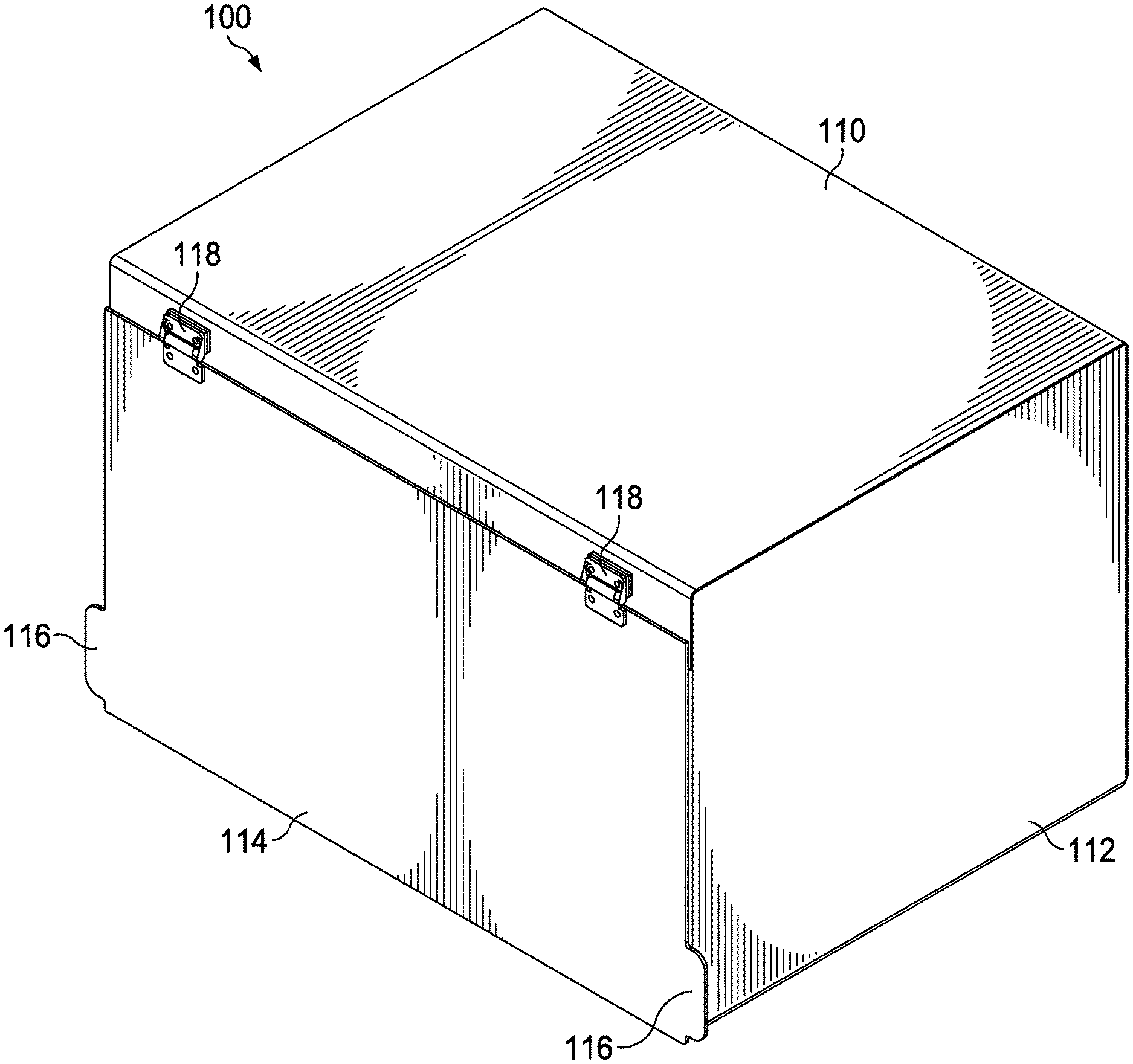
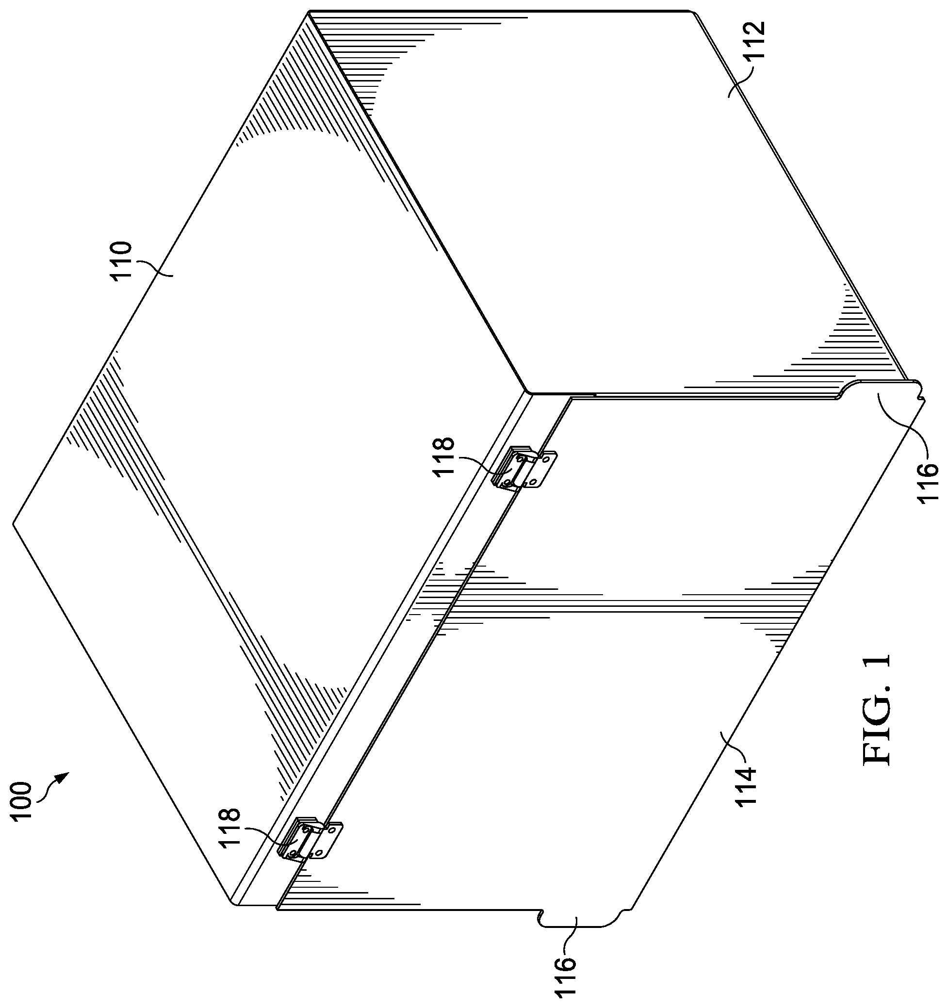
FIG. 1 is a perspective view of an exemplary embodiment of RFID box in accordance with the present invention;
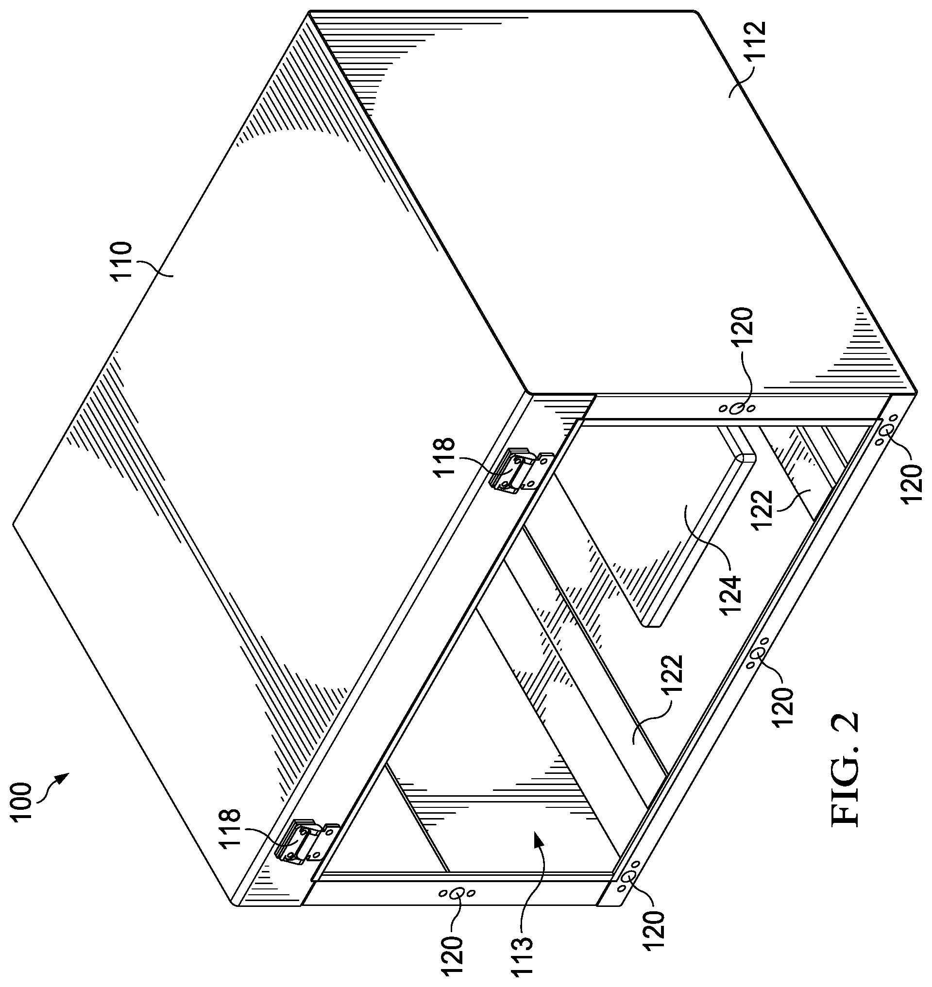
FIG. 2 is a perspective view of the device of the RFID box of FIG. 1 illustrated with the door removed to show in the interior of the RFID box;
FIG. 3 is a perspective view similar to FIG. 2 shown with some of the interior elements removed to further illustrate the interior of the RFID box;
FIG. 4 is a front perspective view of the RFID box of FIG. 1 illustrated with the door removed to show the interior of the RFID box;
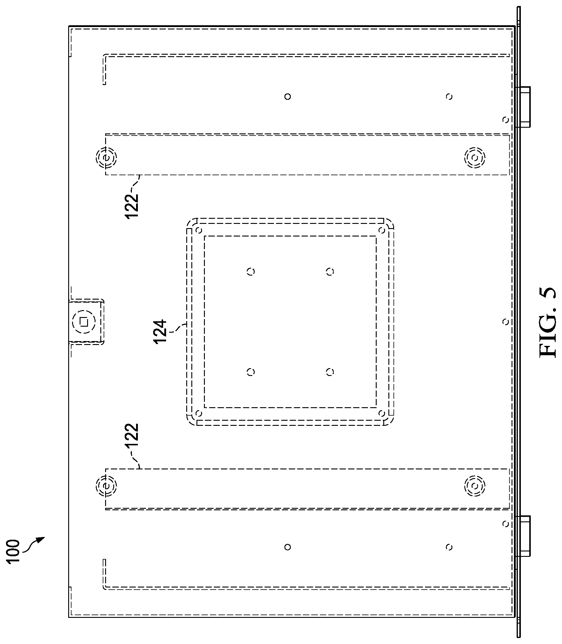
FIG. 5 is a bottom view of the RFID box of FIG. 1;
FIG. 6 is a rear view of the RFID box of FIG. 1 indicating section line A-A;
FIG. 7A is a side sectional view taken along section line A-A of FIG. 6 and indicating Detail A;
FIG. 7B is a detailed side sectional view of Detail A shown in FIG. 7A;
FIG. 8 is a plan view of an exemplary system in accordance with the present invention;
FIG. 9 is a flow chart of exemplary logic for use with the system of FIG. 8 and in accordance with the present invention;
FIG. 10 is a front perspective view of another exemplary embodiment of the RFID box of the present invention;
FIG. 11 is a front perspective view of the device of FIG. 10 shown with the door in an opened position and indicating Detail B and Detail C;
FIG. 12 is a detailed front perspective view of Detail B shown in FIG. 11;
FIG. 13 is a detailed front perspective view of Detail C shown in FIG. 11;
FIG. 14 is a detailed front perspective view of an exemplary pass through device used with the RFID box of FIG. 10;
FIG. 15 is a perspective view of an inventory basket used with the RFID box of FIG. 10;
FIG. 16 is a perspective view of the RFID box of FIG. 11 with the inventory basket of FIG. 15 located therein;
FIG. 17A is a rear view of an exemplary RFID tag for use with the present invention;
FIG. 17B is a front view of the RFID tag of FIG. 17A;
FIG. 18 is a perspective view of an exemplary RFID distribution box;
FIG. 19 is a perspective partially transparent view of the device of FIG. 18;
FIG. 20 is an exploded view of the device of FIG. 18;
FIG. 21 is a top plan view of the device of FIG. 18 with transparency;
FIG. 22 is a front elevation view of the device of FIG. 18 with transparency;
FIG. 23 is a side elevation section view taken through line 23-23 of FIG. 22;
FIG. 24 is a front elevation view of the device of FIG. 18 with transparency;
FIG. 25 is a side elevation section view taken through line 25-25 of FIG. 24;
FIG. 26 is a perspective view of a further exemplary RFID distribution box;
FIG. 27 is a further perspective view of the device of FIG. 26;
FIG. 28 is another perspective view of the device of FIG. 26;
FIG. 29 is another perspective view of the device of FIG. 26;
FIG. 30 is another perspective view of the device of FIG. 26;
FIG. 31 is another perspective view of the device of FIG. 26;
FIG. 32 is a plan view of an element of a process control unit of the device of FIG. 26;
FIG. 33 is a plan view of an element of a process control unit of the device of FIG. 26.
FIG. 34 is a perspective view of a further exemplary RFID distribution box;
FIG. 35 is another perspective view of the device of FIG. 34;
FIG. 36 is a front elevation view of the device of FIG. 34;
FIG. 37 is another perspective view of the device of FIG. 34;
FIG. 38 is a perspective view of an exemplary embodiment of a double door RFID box;
FIG. 39 is a perspective view of the exemplary embodiment of FIG. 38, with the outer door in an open position;
FIG. 40 is a perspective view of the exemplary embodiment of FIG. 38, with both the outer and inner doors in an open position;
FIG. 41 is a top plan view of the exemplary embodiment of FIG. 38; with the doors in a closed position;
FIG. 42 is a left side elevational view of the exemplary embodiment of FIG. 38 with the doors in a closed position;
FIG. 43 is a perspective view of the exemplary embodiment of FIG. 38, with the doors in an open position and the drop box in and open position;
FIG. 44 is a top plan view of the exemplary embodiment of FIG. 38, with the doors in an open position and the drop box in an open position;
FIG. 45A is a front elevational view of the exemplary embodiment of FIG. 38;
FIG. 45B is a side sectional view taken along section line A-A of FIG. 45A;
FIG. 45C is a side sectional view of Detail B shown in FIG. 45B;
FIG. 46 is a front elevational view of the exemplary embodiment of FIG. 38 with transparency.
DETAILED DESCRIPTION OF THE INVENTION
FIG. 1 though FIG. 7B illustrate an exemplary embodiment of an RFID box 100 in accordance with the present invention. In exemplary embodiments of the present invention, the RFID box 100 is rectangular in shape and comprises a housing. The housing may comprise a door 114, an enclosure 110, and a pair of side panels 112. This is merely exemplary, as any size and shape RFID box 100 is contemplated along with any number of components constituting the housing of said RFID box 100.
The enclosure 110 may be C-shaped such that it forms the top, rear, and bottom surfaces of the housing and surrounds an interior cavity 113 that is accessible through the door 114. The enclosure 110 may additionally include a lip that extends vertically from the top and the bottom surfaces such that it forms a portion of the front surface of the housing and partially defines an aperture in the front surface of the housing. The pair of side panels 112 may be configured to fit within the enclosure 110 on either side thereof such that the side panels 112 forms the side surfaces of the RFID box 100. In exemplary embodiments of the present invention, the side panels 112 may be open top box shaped such that they likewise create a lip that protrudes inwardly from the left and right side panels such that it forms a portion of the front surface of the housing and partially defines an aperture in the front surface of the housing.
One or more hinges 118 may connect the door 114 to the housing such that the RFID box 100 is completely enclosed. In exemplary embodiments of the present invention, a pair of hinges 118 are located on the lip formed along the upper edge of the enclosure 110 and connect the door 114 to the enclosure 110. This may reduce sagging of the door 114 otherwise resulting from placing the hinges on the side of the RFID box 100. Sagging of the door 114 may create gaps in the RFID box 100 housing and result in electromagnetic leakage.
In exemplary embodiments of the present invention, the hinges 118 are continuous tension hinges that are configured to bias the door 114 in the opened position, preferably at a 170.degree. angle from the front surface of the RFID box 100. The door 114 may be sized and located to cover the front of the RFID box 100 and be substantially flush with the side and bottom edges thereof, thereby preferably overlapping with at least a portion of the lip created by the enclosure 110 and the side panels 112. In exemplary embodiments of the present invention, the door 114 may comprise one or more tabs 116 that protrude beyond the side panels 112 to facilitate a user manipulating the door 114 between a closed position and an opened position. In other exemplary embodiments of the present invention, the door 114 may comprise pull handles, knobs, or other devices for opening and closing the door 114.
As best shown in FIG. 2 through FIG. 4, the lip extending around the front of the RFID box 100 may further comprise a number of latches 120. These latches 120 may be configured to temporarily secure the door 114 in the closed position against the housing. The latches 120 may be magnetic devices configured to interact with the door 114 itself or magnets located thereon such that the door 114 is held securely in place against the housing until acted upon by a user.
FIG. 2 through FIG. 4 also illustrates the interior of the RFID box 100. A pair of guide rails 122 may be used to guide an inventory basket 238 (best shown in FIGS. 15-16), tray, or other container for various objects to be inventoried. Any number, size, shape, or location of guide rails 122 are contemplated. In exemplary embodiments of the present invention, the guide rails 122 are configured to mate with the inventory basket 238 or other container and keep it centered as it is placed within the RFID box 100.
A gasket 132 may be located along the perimeter of the front surface of the housing for the RFID box 100. In exemplary embodiments, the gasket 132 may extend along the lip created by the enclosure 110 and the side panels 112. The gasket may be comprised of a conductive material and may be a foam, tape, pad, or the like. An RFID antenna 124 may be located along the bottom surface of the RFID box 100. The RFID antenna 124 may be configured to communicate with a series of RFID tags 300 (as shown in FIGS. 17A-C, for example). Preferably, the guide rails 122 are configured to keep the inventory basket 238 or other container above the RFID antenna 124 and thus prevent inadvertent contact or damage.
As best illustrated in FIG. 7A, an RFID antenna/reader 128 may be located along the top of the RFID box 100. The location of the RFID antenna 124 and RFID antenna/reader 128 are merely exemplary, any location is contemplated. Further, any number of RFID antennas 124 and RFID antenna/reader 128 are contemplated. The RFID antenna 124 and the RFID antenna/reader 128 may be electrically connected, preferably by a wire 130. The wire 130 may comprise wire for supplying power to components of the RFID box 100, including, but not limited to, the RFID antenna 124 and the RFID antenna/reader 128, as well as wire for facilitating the communication of data to and from components of the RFID box 100, including but not limited to the RFID antenna 124 and the RFID antenna/reader 128. In order to minimize electromagnetic leakage, the wire 130 may exit the RFID box 100 thorough a pass through device 126.
In exemplary embodiments of the present invention, the pass through device 126 may be configured to cover the aperture in the RFID box 100 where the wire 130 passes outside of the RFID box 100. The pass-through device 126 may comprise an enclosure defining a channel which extends along the rear wall of the RFID box 100 for the wire 130 to pass through. The pass through device 126 may be fastened, welded, or otherwise adhered to the inside rear wall of the RFID box 100. Preferably, conductive tape is used along the seams between the pass through device 126 and the RFID box 100 to minimize electromagnetic leakage. The pass through device 126 may comprise a coupler 134 (as best illustrated in FIG. 7B) that connects the internal wire 130 to an external wire 131. The coupler 134 may be configured to substantially seal the aperture otherwise required to allow the wire 130 to pass outside of the RFID box 100. In exemplary embodiments of the present invention, the coupler 134 may be a female to female Ethernet and power connector.
One or more mechanical stops 119 may be located along the rear wall of the RFID box 100, though such is not required. The mechanical stops 119 may be configured to prevent the inventory basket 238 or other container from contacting the pass through device 126 and/or the rear wall of the RFID box. In other exemplary embodiments of the present invention, the pass through device 126 may act as a mechanical stop 119.
The components of the RFID box 100, including, but not limited to, the enclosure 110, the side panels 112, and the pass-through device 126 may be fastened, welded, adhered, or otherwise secured in their respective locations preferably by conductive materials. Conductive tape or other conductive material may be additionally placed along the seams of the components of the RFID box 100 so as to minimize RFID leakage. These components may be comprised of a metallic, conductive material such as, but not limited to, aluminum. Specifically, they may be comprised of 1/8'' thick aluminum, though any thickness is contemplated. The use of a conductive material may serve to substantially electromagnetically "seal" the RFID box 100, thus minimizing RFID leakage, which thereby ensures accuracy in RFID readings by ensuring that the RFID antenna 124 and RFID antenna/reader 128 only detect RFID signals being emitted from within the RFID box 100.
FIG. 8 is a plan view of an exemplary system in accordance with this invention. The system may comprise the RFID box 100, a server 140, and an electronic device 150. The RFID box 100 may be electrically connected to the server 140, which may be electrically connected to the electronic device 150. The electrical connection may be wired or wireless. In exemplary embodiments of the present invention, the server 140 is located remote from the RFID box 100 and the electronic device 150. For example, without limitation, the server 140 may be a cloud based data storage and processing server. Likewise, the electronic device 150 may be located remote from the server 140 and the RFID box 100. The RFID box 100, server 140, and electronic device 150 may be connected via the world wide web, the internet, intranet, or other communications network. The electronic device 150 may be a laptop, personal computer, tablet, smart phone, or the like.
FIG. 9 is a flow chart of exemplary logic for use with the system of FIG. 8. Initially, the RFID box 100 may perform a scan of the inventory located therein. This may be accomplished by known methods. The data pertaining to contents of the RFID box 100 and related information are hereinafter referred to as the baseline box content data. In other exemplary embodiments of the present invention, the baseline box content data may be generated in whole or part by manual entry. This baseline box content data may include the contents of the RFID box 100, names for the contents, serial numbers, and the like. For example, but without limitation, the RFID box 100 may be used in a medical setting for the inventory of medications. In such a case, the baseline box content data may include the number, type, name, expiration date, prescribing physician, date stored, date removed, and the like for each medication in the RFID box 100. Of course, this application is merely exemplary and is not intended to be limiting. Any application for the RFID box 100 is contemplated.
The baseline box content data may be transmitted to and stored on the server 140. At a later time, the contents of the RFID box 100 may be scanned and the data recorded, this data is hereinafter referred to as the current box content data. The current box content data may then be transmitted to the server 140 for storage and processing. The server 140 may compare the current box content data with the baseline box content data and produce summary of the comparison, hereinafter referred to as the comparison data. The comparison data may then be transmitted to the electronic device 150 for display.
FIG. 10 through FIG. 16 illustrates another exemplary embodiment of the present invention. In these figures, like elements have been labeled similarly to the first embodiment (e.g., RFID box 200, interior enclosure 213, door 214, tabs 216, guide rails 222, etc.). FIG. 11 through FIG. 13 illustrate how the latches 220 may interact. For example, the latches 220 may be magnetic devices placed on the lip of the RFID box 200 and may be configured to interact with a series of magnets 221 placed on the door 214. The magnets may be located and oriented such that they are attracted to one another and hold the door 214 shut when the door 214 is located in a closed position.
FIG. 14 illustrates the rear view of and interior of another exemplary pass through device 226. In the present embodiment, the pass-through device 226 may be substantially rectangular in shape and contain the coupler 234 positioned on a bottom portion thereof and extended between a plate that substantially fills the interior of the pass-through device 226.
In exemplary embodiments of the present invention, as illustrated in FIGS. 15 and 16, the inventory basket 238 may be sized and configured to substantially fill the interior cavity of the RFID box 200. The inventory basket 238 may comprise grab handles 239 for ease of use.
FIGS. 17A and 17B illustrate an exemplary RFID tag 300 for use with the present invention. The RFID tag 300 may comprise a tail section 302 connected to a first tab 304, which is connected to a second tab 306. The first tab 304 and the second tab 306 may be separated by a perforation 308. Some or all of the rear surface of the RFID tag 300 may comprise an adhesive such that the RFID tag 300 may be placed on an object to be inventoried, such as, but not limited to, a medication container. The tail section 302 may be sized and configured to wrap around an object to be inventoried such that the first tab 304 sticks out from the object to be inventoried. Preferably, the tail section 302 has a reduced thickness relative to the first and second tabs 304 and 306 such that the object to be inventoried can be clearly seen. For example, without limitation, if placed around a medicine container, the label on the container and the drug itself can be clearly viewed. The second tab 306 may be removed, preferably along the perforation 308, and adhered to an object to be inventoried. In other exemplary embodiments, the second tab 306 may be folded onto the first tab 304 along the perforation 308 to form a flag.
The first tab 304 and the second tab 306 may each comprise an identification number 312 and/or a code 314 such as, but not limited to, a bar code, QR code, or the like. The second tab 306 may further comprise an RFID antenna 310 configured to communicate with the RFID antennas 124 and the RFID antenna/reader 128.
In an exemplary embodiment, each tab 306, 304 has a length of approximately 1.189 inches and a height of 0.6 inches. The tail has a height of 0.188 inches. The RFID tag 300 has an overall length of 4.75 inches, prior to any folding. The RFID tag has a thickness of 0.005 inches. In other embodiments, the dimensions of the RFID tag may vary as desired. Any size, shape, or design of the RFID tag 300 is contemplated.
A further exemplary embodiment of the invention that includes access control and auditing features is depicted in connection with FIGS. 18-25. In applications in which the present invention is deployed in connection with control substance inventories and other similarly controlled and dangerous items, it may be desirable for access to such inventories to be monitored and controlled. In the case of pharmaceutical deployment, for instance, such as at a healthcare facility, drugs inventoried utilizing the RFID box discussed herein may be distributed about the facility for use and expedient access during the provision of healthcare services. For example, distribution boxes such as box 400 may be placed in convenient locations throughout a facility for access by healthcare professionals, patients and the like, as needed.
In some embodiments, the distribution boxes may be networked with an inventory system such as shown in connection with FIG. 8 above, and may log deposits and withdraws of an inventory kit or basket and the contents thereof at each event. In other embodiments, the distribution boxes may be configured to authenticate a user attempting to access the box before access is granted. In some of these embodiments, the distribution boxes may further or separately track box access for audit purposes or regulatory compliance, for example, such as for use in furthering Joint Commission (JCAHO) compliance goals.
An exemplary embodiment of the distribution box 400 is shown with Faraday cage construction shielding methods similar to those described in connection with the RFID box 100. An enclosure 410 may be C-shaped such that it forms the top 402, rear 404, and bottom 406 surfaces of the housing. The enclosure 410 may additionally include lips 408 and 409 that extend vertically from the top 402 and the bottom 406 surfaces such that it forms a portion of the front surface of the housing and partially defines an aperture 411 in the front surface of the housing. In some embodiments, it may be convenient to mount the invented distribution box 400 on a vertical surface, such as the wall of a hospital operating room or patient room, such that mounting brackets 413 are provided for securing said box 400 to said vertical surface. A pair of side panels 412 may be configured to fit within the enclosure 410 on either side thereof such that the side panels 412 forms the side surfaces of the distribution box 400. In exemplary embodiments of the present invention, the side panels 412 may be open top box shaped such that they likewise create a lip that protrudes inwardly from the left and right side panels such that it forms a portion of the front surface of the housing and partially defines an aperture 411 in the front surface of the housing.
One or more hinge mechanisms 418 may connect the door 414 to the housing such that the distribution box 400 is completely enclosed. In an exemplary embodiment of the present invention, one or more hinges 418 are located on the lip formed along the upper edge of the enclosure 410 and connect the door 414 to the enclosure 410. This may reduce sagging of the door 414 otherwise resulting from placing the hinges on the side of the distribution box 400. Sagging of the door 414 may create gaps in the distribution box 400 housing and result in electromagnetic leakage, which is undesirable in applications in which the inventory items in a kit are being logged.
In exemplary embodiments of the present invention, the hinges 418 are continuous tension hinges that are configured to bias the door 414 in the opened position, preferably at a 170.degree. angle from the front surface of the distribution box 400. The door 414 may be sized and located to cover the front of the distribution box 400 and be substantially flush with the side and bottom edges thereof, thereby preferably overlapping with at least a portion of the front face of the box 400 created by the lips of the enclosure 410 and the side panels 412. In exemplary embodiments of the present invention, the door 414 may comprise one or more tabs 416 that protrude beyond the side panels 412 to facilitate a user manipulating the door 414 between a closed position and an opened position. In other exemplary embodiments of the present invention, the door 414 may comprise pull handles, knobs, or other devices for opening and closing the door 414.
As best shown in FIG. 20, the lip extending around the front of the distribution box 400 may further comprise a number of latches 420. The latches 420 may be configured to temporarily secure the door 414 in the closed position against the housing. The latches 420 may be magnetic devices configured to interact with the door 414 itself, magnets located thereon such that the door 414 is held securely in place against the housing until acted upon by a user, or similar spring-biased mechanical equivalents, for example.
A gasket 432 may be located along the perimeter of the front surface of the housing for the distribution box 400. In exemplary embodiments, the gasket 432 may extend along the lip created by the enclosure 410 and the side panels 412. The gasket 432 may be comprised of a conductive material and may be a foam, tape, pad, or the like. The door 416 may further be provided with additional insulation or electromagnetic shielding material, as at 417. Similarly, an interior enclosure 419 with an open face may be affixed within the enclosure 410 and generally within the box 400, wherein the open face 421 is aligned with the aperture 411. The interior enclosure 419, which surrounds the interior cavity 415, may be used to provide additional electromagnetic insulative capacity to the box 400, and provide a smooth working surface for inventory storage.
A control system 450 is also provided in the exemplary embodiment shown in connection with FIGS. 18-25. In some embodiments, the control system 450 is utilized as an access control or audit system, an inventory tracking system, or a combination thereof. In some embodiments, the distribution box 400 may be configured with an access control or audit system 450 that includes a lock mechanism 452, and authentication mechanism 454, an access control unit 456 and associated communicative coupling means 458. The distribution box 400 may also be provided with a latch 420 secured to the door 416 corresponding to and complementary to said locking mechanism 452, whereupon the door 416 is secured in default a closed position in which the box 400 cannot be opened to access its contents without proper authentication via the authentication means 454.
Depending upon the deployment environment, the authentication means 454 may be provided in a manner conducive and complementary to existing authentication means already in use at a location. For example, a lock access point may be provided which includes an RFID antenna located at a surface of the distribution box 400. The RFID antenna may be configured to communicate with a series of RFID tags 300 (as shown in FIGS. 17A-C, for example), an ID badge, or wrist band, such as the wrist band 460 depicted in connection with FIG. 20. In some embodiments, the authentication means 454 is an RFID antenna secured to the distribution box 400 outside of the shielded envelop of the box 400. When a user wearing an RFID-enabled wrist band 460 or other similar device passes the device 460 in close proximity to the lock access point 454, the RFID antenna receives the ID transmitted by the band 460, and passes the signal via conductive wire 458 to an access control unit 456 for further processing.
An electronic lock mechanism 452 is provided to couple to the door latch 420 to prevent unauthorized access to the contents of the distribution box 400. This lock receives actuation signals from the access control unit 456 via conductive wires 458, which in turn receives and processes inputs from the lock access mechanism 454. In some embodiments, RFID-enabled cards, badges, wrist bands, or bracelets 460 are provided to users, such as hospital staff, and the access control unit 456 is programmed to open the lock mechanism 452 upon a successful scan of a predetermined ID range received at the lock access device 454. In other embodiments, the distribution box 400 may be networked with the RFID inventory box system (see, e.g., FIG. 8) which it may query to determine authorized ID ranges. In the latter case, temporary ID bracelets 460 may be issued, such as for patients, wherein access to a distribution box 400 is restricted to a particular location (e.g., the patient's room) or a particular length of time (e.g., during a hospital stay).
Importantly, the invented distribution box 400 and access control system 450 may be configured to log access to the distribution box 400, either locally in a memory unit of the access control unit 456 or remotely (e.g., 150 in FIG. 8). Therefore, the distribution box 400 ensures an audit trail is created of inventory access at a granular level. A user desiring to view the audit trail may do so by accessing a web portal that provides information about the status and history of items in the box, as well as the users that have accessed the box. The web portal may also be used to change settings, including which users (RFID-enabled cards, wrist bands, or bracelets) are authorized to access the box.
In some embodiments, the lock access mechanism 454 may be configured with other alternative types of access readers, as is desired in a particular application. For example, the lock access mechanism could be provided as an RFID antenna, a biometric reader, a proximity induction-based card reader, a mag-stripe reader, a keypad, or a combination thereof.
In some cases, the distribution box 400 may further include an internal RFID antenna as part of the access control unit 456 for tracking and logging inventory items present both before and after an access event. While the box 400 may be configured with a targeted RF leak at the location of the lock access mechanism 454, exemplary embodiments may include two antennas (internal and external) shielded from one another to track box access and inventory levels. Network access, power source or both for the access control unit 456 may be achieved, for example, via an Ethernet pass-through 462 in the housing 410. Those skilled in the art will appreciate that, while an exemplary configuration of the lock 452 and latch 420 mechanism, lock access reader mechanism 454, access control unit 456 and pass-through 462 is shown in connection with FIGS. 18-25, other suitable configurations are possible without departing from the scope of the instant invention as needed for a particular application. Those skilled in the art will also appreciate that in other exemplary embodiments the box 400 may include a mechanical lock that can be accessed with a physical key in addition to the lock access mechanism. The mechanical lock may provide secondary security or be configured to override the lock access mechanism 454. In such an embodiment, the key may be used to open the box when the power is out.
The components of the distribution box 400, including but not limited to the enclosure 410 and the side panels 412, may be fastened, welded, adhered, or otherwise secured in their respective locations preferably by conductive materials. Conductive tape or other conductive material may be additionally placed along the seams of the components of the RFID box 400 so as to minimize RFID leakage. These components may be comprised of a metallic, conductive material such as, but not limited to, aluminum. Specifically, they may be comprised of 1/8'' thick aluminum, though any thickness is contemplated. The use of a conductive material may serve to substantially electromagnetically "seal" the distribution box 400 thus minimizing RFID leakage, which thereby ensures accuracy in RFID readings by ensuring that an RFID antenna and RFID antenna/reader only detect RFID signals being emitted from within the RFID box 400 for accuracy and efficacy in inventory tracking procedures.
A second exemplary embodiment of a distribution box 500 and its components are shown in connection with FIGS. 26-33. FIG. 26 depicts the exterior of the exemplary box 500, which is formed of a C-shaped housing 510, side panels 512 and a door 514. A lock access mechanism 554 is mounted to the side panel 512, and in this embodiment is an HID-brand proximity card reader unit. In other embodiments, other alternative access mechanisms may be substituted or used in conjunction with such an element as discussed above. Ethernet 564 and power 566 are shown leading to the control unit 556 inside of the enclosure 510. FIG. 30 also depicts the box 500 from a rearward side perspective, and illustrates the entry point of the network cable 564 and mounted reader unit 554.
FIG. 27 illustrates the box 500 with the door 514 in the open position, hinged to the left side of the enclosure 510. The latch 520 is fixed to the right side of the door 514 in a position for complementary mating registration with the electronic latch 552 secured to the box 500 at the lower end of the right side panel 512, below the access reader unit 554. An interior enclosure 519 with an open face is affixed within the enclosure 510 and generally within the box 500. FIG. 28 is a perspective view of the right interior side of the box 500 with the interior enclosure removed. The electronic lock strike 552 is shown mounted therein.
FIG. 29 is a further perspective view of the interior of the box 500 with the interior enclosure 519 removed, primarily focused on the upper portion of the box interior. Here, the elements of the access control unit 556 can be seen, as well as electric connections 558 coupling the components of the control system generally. In this exemplary embodiment, the control unit of the box 500 can be seen to include a processing unit 570, a lock mechanism 552, connections 558, RFID reader 572 and access reader unit 554. In this embodiment, the box 500 is provided with a ThingMagic M6E-MICRO RFID reader unit 572, which is used to receive RFID signals from inventory items and kit baskets placed within or removed from the box 500. The processing unit 570 utilizes a Raspberry Pi 3 Model B Motherboard for processing the RFID information received from the reader 572 and the access reader unit 554, and handling network communications and lock mechanism 552 actuation. FIG. 31 shows a second view of the reader unit 572 for clarity.
FIGS. 32 and 33 depict components of the processing unit 570 used in this exemplary embodiment. The Raspberry Pi 3 Model B Motherboard 580 is shown in FIG. 32, and a daughter card 582 is shown in FIG. 33. The daughter card 582 is secured to the motherboard 580 via threaded fasteners (not shown) screwed into the threaded mounts 584 on the motherboard, via apertures 586 in the daughter card. The daughter card provides the necessary circuitry for actuation of the lock mechanism 552 with suitable boosts to voltage.
In certain embodiments, the processing unit 570 allows for local processing of authorization requests and comparison of baseline information against inventory scans. While changes in user roles and changes to baseline information may be effected through a web portal, the box 500 can perform many operations locally, allowing it to maintain operability even when network/internet connection is unavailable.
Another embodiment of a distribution box 600 having different shape and size is shown in connection with FIGS. 34 through 37. FIG. 34 depicts the exterior of the exemplary box 600, which is formed of a housing 610 and a door 614. In this embodiment, and as best seen in FIG. 37, the door hinges are comprised of tabs 620 formed from the same sheets of metal as the door and cabinet, with a bearing 622 in-between, providing for a seamless appearance. A lock access mechanism (not shown) and card reader unit (not shown) may be mounted to the housing 610 as desired. An interior enclosure 612 defines an interior cavity 613 for receiving items. The box and cavity may be sized to receive a single tray containing pharmaceutical items and/or other items. In an exemplary embodiment, the dimensions of the interior cavity 613 may be 24.5 inches in width, 3.875 inches in height, and 16.7 inches in depth. Of course, in other embodiments the dimensions of the interior cavity 613 may vary as desired. While this embodiment could be attached to a wall, it may also be placed on a surface such as a counter top or on top of a cabinet 700, as shown in FIG. 37. In some embodiments the box may contain bottom brackets allowing it to be secured to surface. The compact nature of the box allows it to be used in locations that may have little space available, such as a fire station.
As shown in FIGS. 35 and 36, the box 600 has four adjustable feet 615, each located at a bottom corner of the box, which may be adjusted as necessary to allow the box 600 to be level or avoid wobbling when in use.
The box 600 may have a status light 617 located on the housing. The status light 617 may display one or more colors that communicate information to a user. In an exemplary embodiment, the light can turn green, orange and red. When a scan reveals that all items are present, and all items are unexpired, the light 617 may be green. A user can take one look at the box and upon seeing the green light know that there is no need to replace any expired items, and that all items are present. The light 617 turns orange when one or more items are expired, providing a visual notification to the user that restocking is necessary. When the scan indicates that according to baseline box content data an item is missing, the box may turn red, again providing a visual notification to the user that restocking is necessary and possibly a review of the audit records is necessary as well to see what user removed the item. Of course, in different embodiments, the light may be configured in different ways. The light may be an LED light in electronic communication with the motherboard 580. The box 600 may be powered by PoE (power over ethernet) or other means. An ethernet port may be located on its back side or other surface. In some embodiments, the box may include a battery to allow it to remain operable when the power goes out or during transport.
This embodiment may have a mechanical lock in addition to the lock operated by the lock access mechanism. The mechanical lock may be completely separate to and provide a secondary level of security to the lock access mechanism. This may allow for increased security. The mechanical lock may also be configured to override the lock access mechanism in times when the power is out or in other emergency situations.
Different embodiments may also have a display screen integrated into the box itself to provide written notifications to users. For example, the screen may display the name of a pharmaceutical item that has expired along with its expiration date. In some embodiments, the screen may display the name of the last user that has accessed the box. The screen may be sized such that it can only provide a few words to a user or it may be larger and even have touch-screen capabilities to allow users to configure settings, enter queries, or otherwise obtain information about contents and access history.
It will be appreciated by one of ordinary skill in the art that a box shaped like the embodiment in FIGS. 34 through 37 may contain many of the features shown in other embodiments of the figures as desired to provide a convenient solution to a consumer.
FIGS. 38 through 46 illustrate an exemplary embodiment of a double door RFID box 700. In this exemplary embodiment, the RFID box 700 is rectangular in shape and comprises a housing 710. The housing 710 is comprised of a front side 712, left side 714, right side 716, top side 718, bottom side 720, and back side 722, surrounding an inner cavity 724.
Located on the front side 712 of the housing 710 is an outer door 726 which may be attached to the housing 710 by a hinge mechanisms 728. In the exemplary embodiment of FIGS. 38-46, the hinge mechanism 728 movably connects the left side of the outer door 726 to the left edge of the front side 712 of the housing 710. In other embodiments, different means may be used to connect the outer door 726 to the housing in a variety of ways. As shown at least in FIGS. 38, 41 and 44, the outer door 726 may have a lip 729 on the end opposite the hinge mechanism 728 that extends away from the outer door 726 in a curving fashion in order to aid a user in manually opening and closing the outer door 726.
While in FIG. 38 the outer door 726 is shown in a closed position, in FIG. 39 the outer door 726 is shown in a substantially open position, wherein a user can view and access an inner door 730 located in a recess 731 in the front side 712 of the housing 710. The inner door 730 is connected to the recessed wall via a hinge mechanism. The inner door also has a lip 727 that can be used to manually move the door. FIGS. 40, 43, and 44 show the box 700 with both the outer door 726 and inner door 730 in open positions, allowing a user access to the inner cavity 724 of the box 700.
In this exemplary embodiment both the outer door 726 and inner door 730 are associated with electromechanical lock access mechanisms 732, 734 to allow for access into the RFID box. Each of the lock access mechanisms 732, 734 are electrically actuated, but also contain manual override locks 733, 735 that can bypass the electric actuation. The manual override locks 733, 735 can be accessed from the front face of the outer and inner doors 726, 730. The manual override locks 733, 735 may be keyed differently such that two different keys are needed to open both the outer and inner doors. Manual access may be necessary in the event of an electrical outage or the box 700 otherwise loses access to a power supply. Each lock access mechanism 732, 734 comprises a latch 738, 740 on the back side of its respective door that insertably engages with an aperture located in the housing 710 when in the "locked" orientation (apertures not shown). The apertures may be located within the recess 731 on the front side 712 of the housing.
The RFID box 700 includes an internal processing unit for controlling operations of the box 700, including access to the inner cavity. Referring to FIG. 46, the internal processing unit 736 is located within the housing, and in an exemplary embodiment may be located between the bottom side 720 of the housing 710 and the inner cavity 724. The internal processing unit may comprise a single board computer (SBC) associated with a printed circuit board (PCB). In an exemplary embodiment, the SBC may be a Raspberry PI Model 3, although other embodiments may use a variety of commercially-available processing units to perform the same functions. The SBC includes wireless capabilities that permit wireless connectivity to a wireless network via an external wireless antenna 741 located on the box 700. While shown in FIGS. 38-42, the wireless antenna 741 is not shown in FIGS. 43-46. The PCB may interface the low voltage signals of the SBC with the other devices, including an RFID radio module connected directly to the PCB, the electromechanical lock access mechanisms 732, 734, the access reader unit 737 located on the right side of the housing, and the LED light 750.
The access reader unit 737 is the source of authentication for the electronic actuation of the lock access mechanisms 732, 734. In some embodiments, the access reader unit 737 may be a proximity card reader. The PCB is also in electronic communication with an RFID antenna 743 located in the housing 710 of the box 700. As illustrated in FIGS. 45B and 46, the RFID antenna 734 is located between the back side 722 of the housing the inner cavity 724. The RFID antenna 734 may be connected by coaxial cable to an RFID reader module connected to PCB. In an exemplary embodiment, the RFID reader module may be a ThingMagic Micro Embedded RFID Reader Module, however in other embodiments a variety of other commercially-available RFID reader modules may be used.
As with other embodiments disclosed herein, one or more wires (not shown) may be used to facilitate communication between the various components of the box 700 and the internal processing unit, as well as supply power. The box 710 may be mains-powered and may be powered by PoE or other means. Referring to FIG. 46, an internal power supply 760 is also shown.
One or ordinary skill in the art will recognize that any location, variation, or combination of RFID antenna and RFID readers is contemplated, including versions described in other embodiments herein. Additionally, although a single antenna may be used to scan the entire volume of the inner cavity 724, in other embodiments multiple antennas, readers, or antenna/readers may be used to read RFID tags located in the box 700.
Referring to FIGS. 41-45, located on the top side 718 of the box is a lockable drop box mechanism 744. The drop box mechanism 744 comprises a pivotable drawer 746 with a finger slot 748 that allows for manual opening of the drawer 746 when the drawer 746 is in a closed and unlocked state. The drawer 746 allows items to be placed into the inner cavity 724 of the box 700 when the inner door 730 is closed. When the drawer 746 is in an open position an item can be placed into the drawer 746 by a user. The drawer 746 can then be manually pushed into a closed position, when the item will drop into the inner cavity 724. The drawer 746 may also close shut under the force of gravity, such that it is only in an open position when a user is holding it open. In some embodiments, the drawer 746 may have a lip, handle, knob, or other feature that aids a user in opening and closing the drawer 746. In some embodiments, the drop box mechanism 744 may be automated such that the opening and closing of the drawer 746 can be initiated by manipulating a button or switch.
As illustrated
References
-
fda.gov/ICECI/ComplianceManuals/CompliancePolicyGuidanceManual/ucm074357.htm
-
outpatientsurgery.net/resources/forms/2004/pdf/OutpatientSurgeryMagazine0410crashCart.pdf
-
citrenz.ac.nz/bacit/0301/2005HoulistonRFID.htm
-
businesswire.com/news/home/20090615005349/en/McKesson-Announces-Touch-Screen-Driven-Medication-Dispensing-Solution#.NR7quPnF10
-
medpak.com/v1/news/20060201CSFLAG.pdf
-
rfidjounal.com/articles/pdf?4046
-
rfidjournal.com/articles/pdf?1081
-
-
ieeexplore.ieee.org/document/4438162
-
-
-
-
elsevier.com
-
-
wikipedi.org/w/index.php?title=Faraday
-
arrow.dit.ie/engschcecon
-
kitcheck.com/2014/06/new-kit-check-smaller-rfid-scanning-station-little-blue-box
-
-
youtube.com/watch?v=UvNnoZYgGW4
-
-
-
-
-
pppmag.com/article/2119
-
D00000
D00001
D00002
D00003
D00004
D00005
D00006
D00007
D00008
D00009
D00010
D00011
D00012
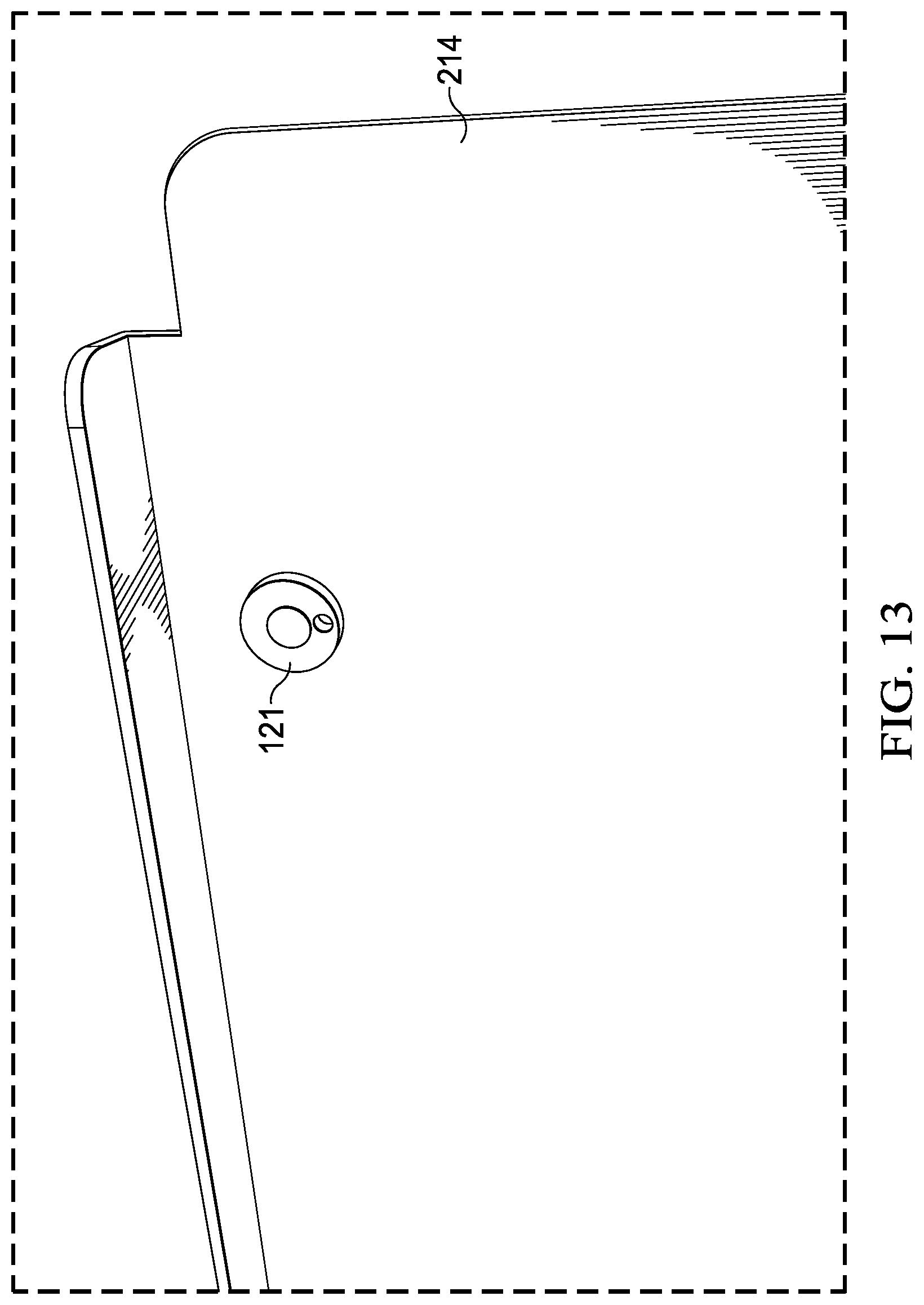
D00013
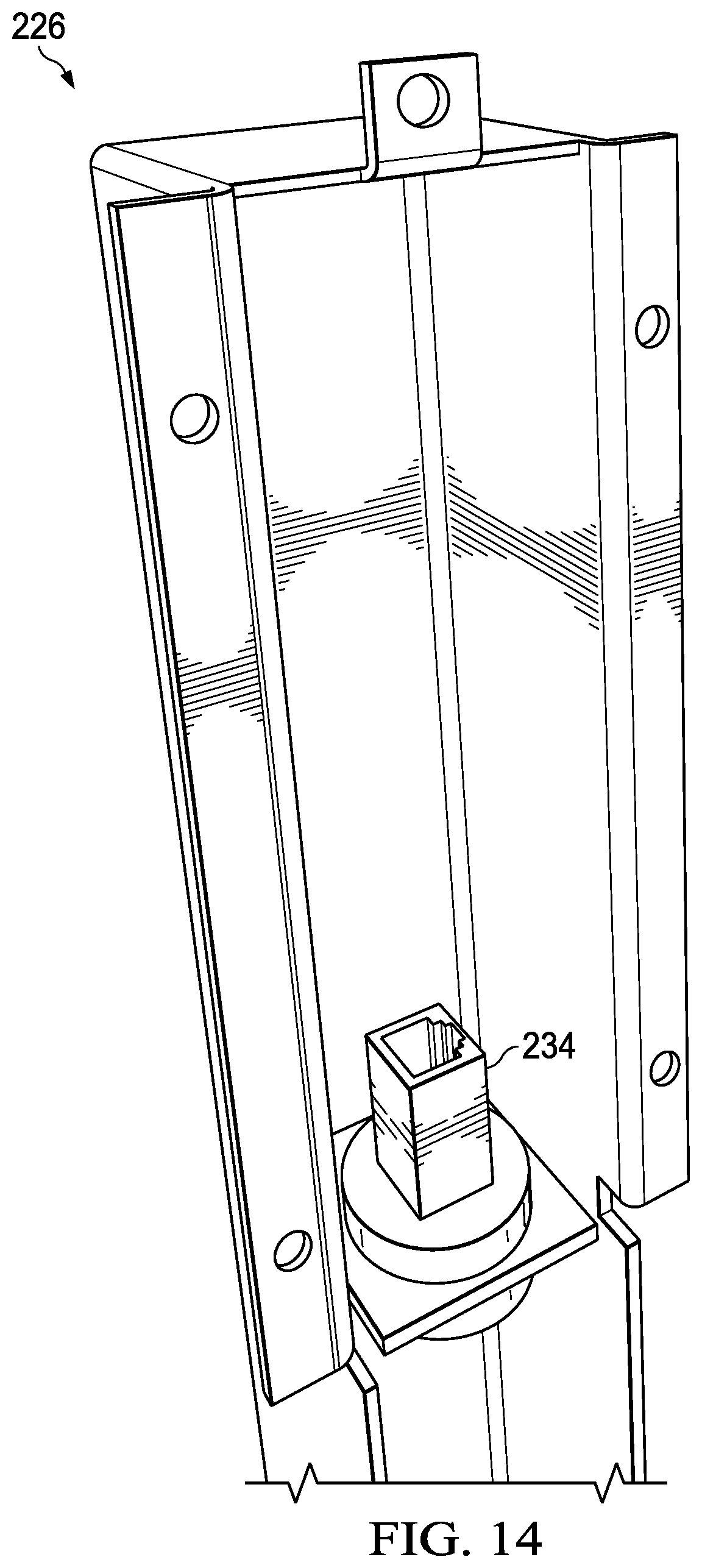
D00014

D00015
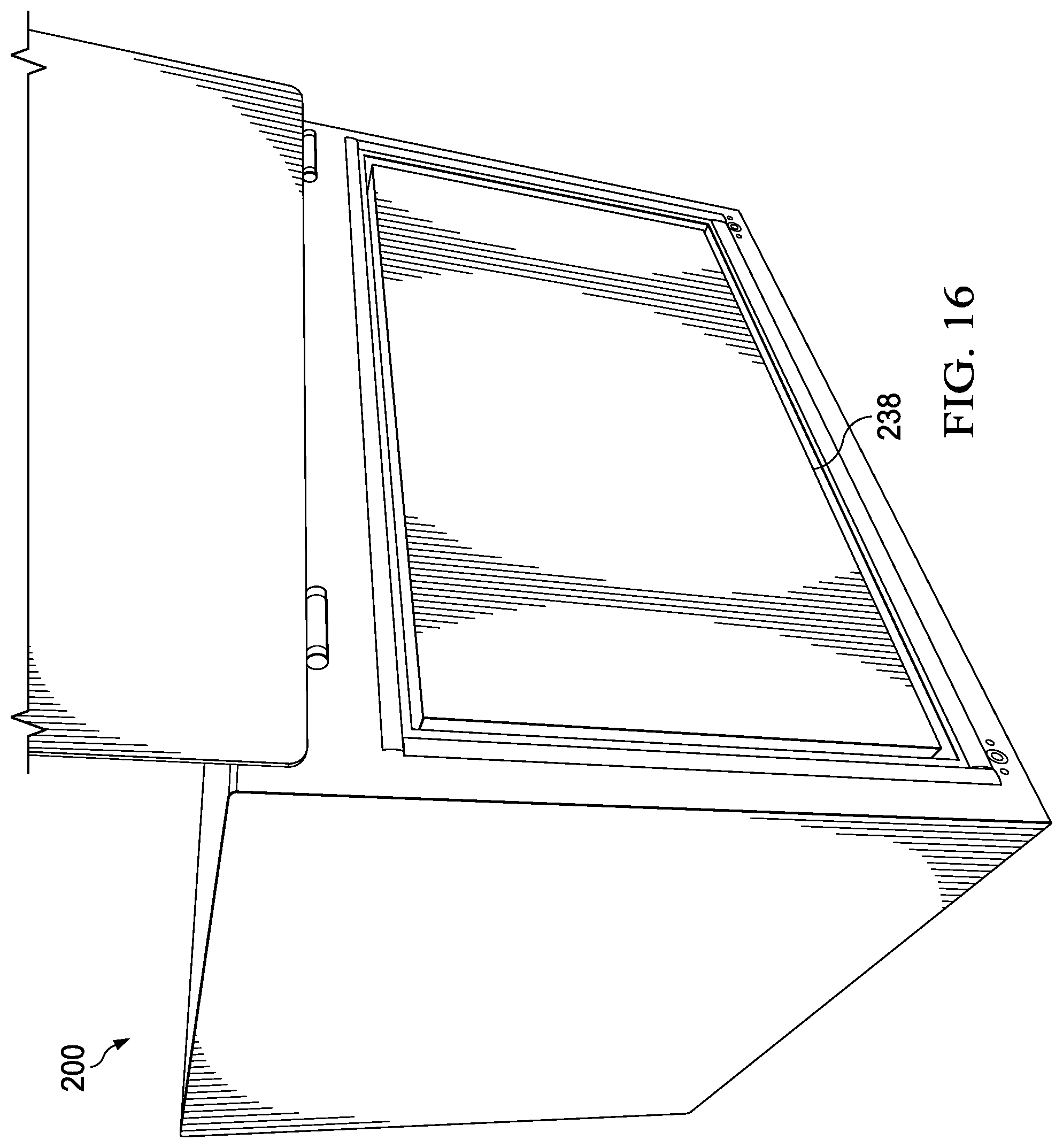
D00016
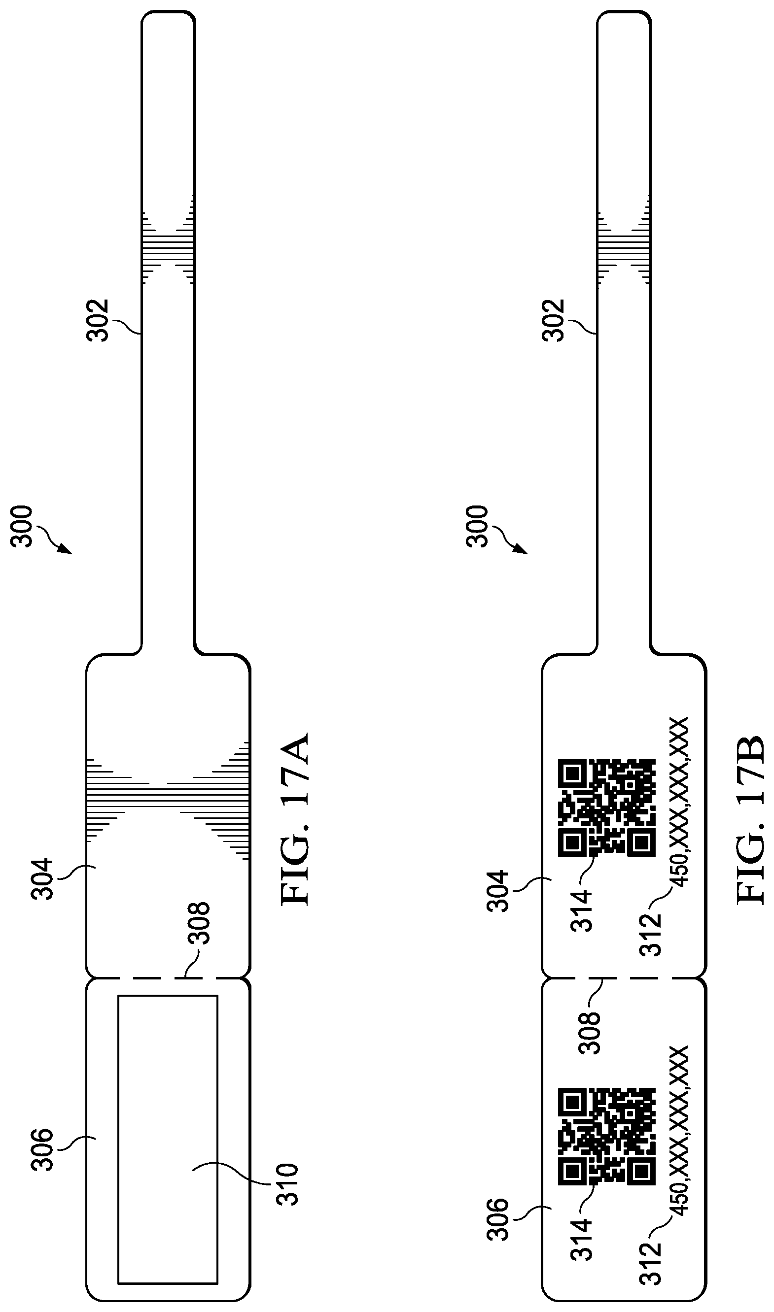
D00017

D00018

D00019
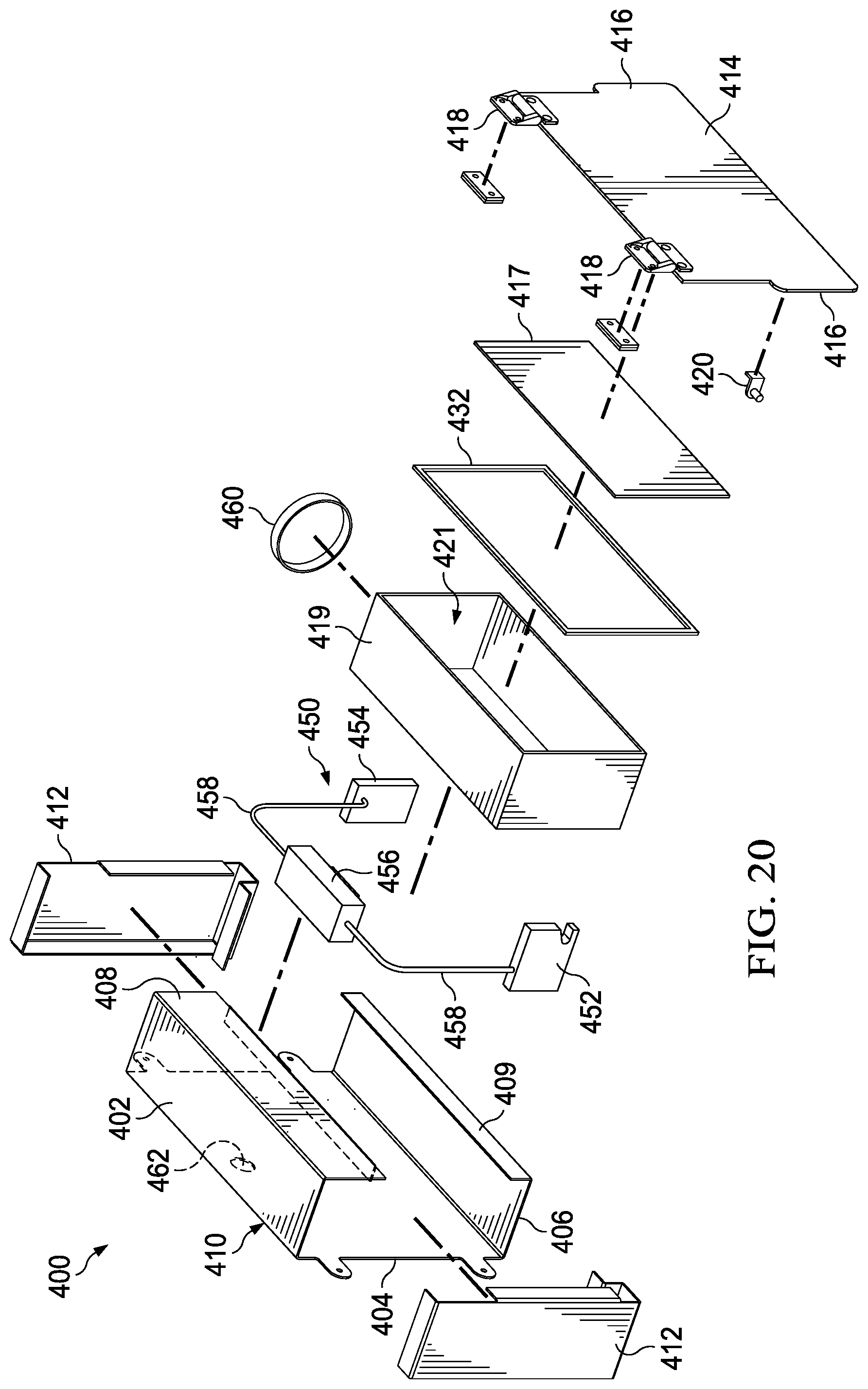
D00020

D00021

D00022

D00023
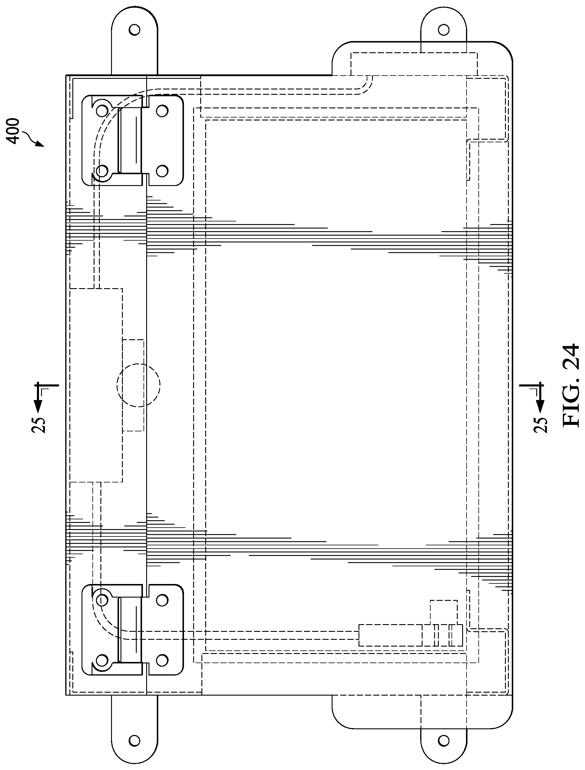
D00024
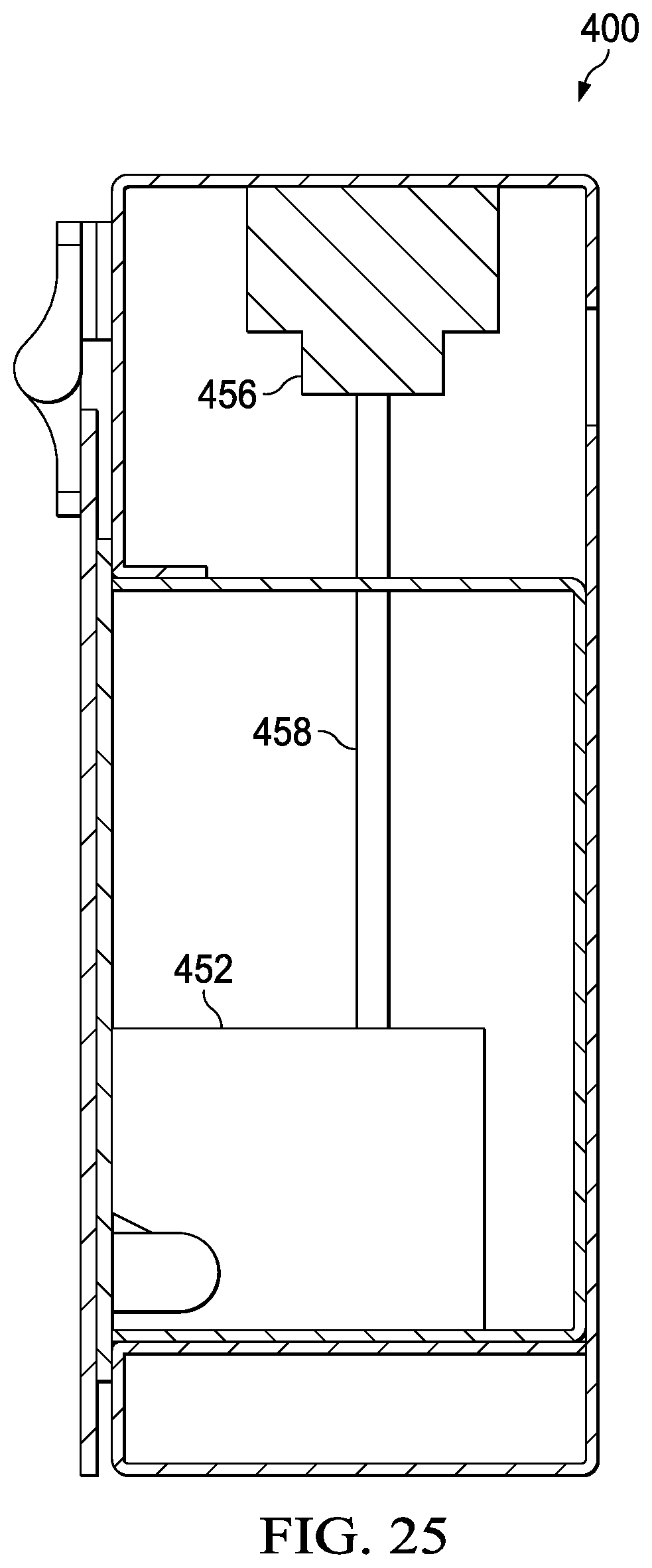
D00025

D00026
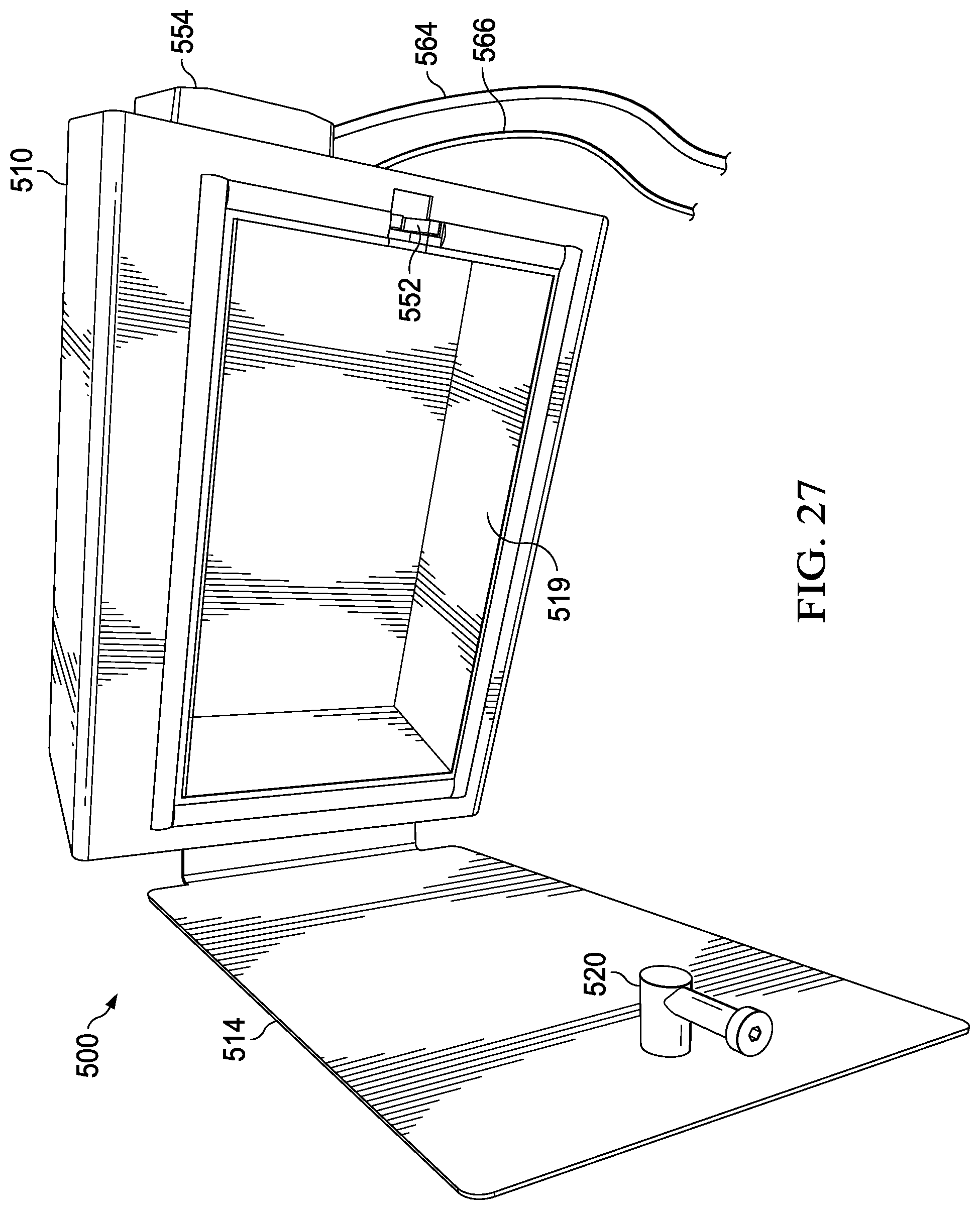
D00027

D00028

D00029

D00030

D00031
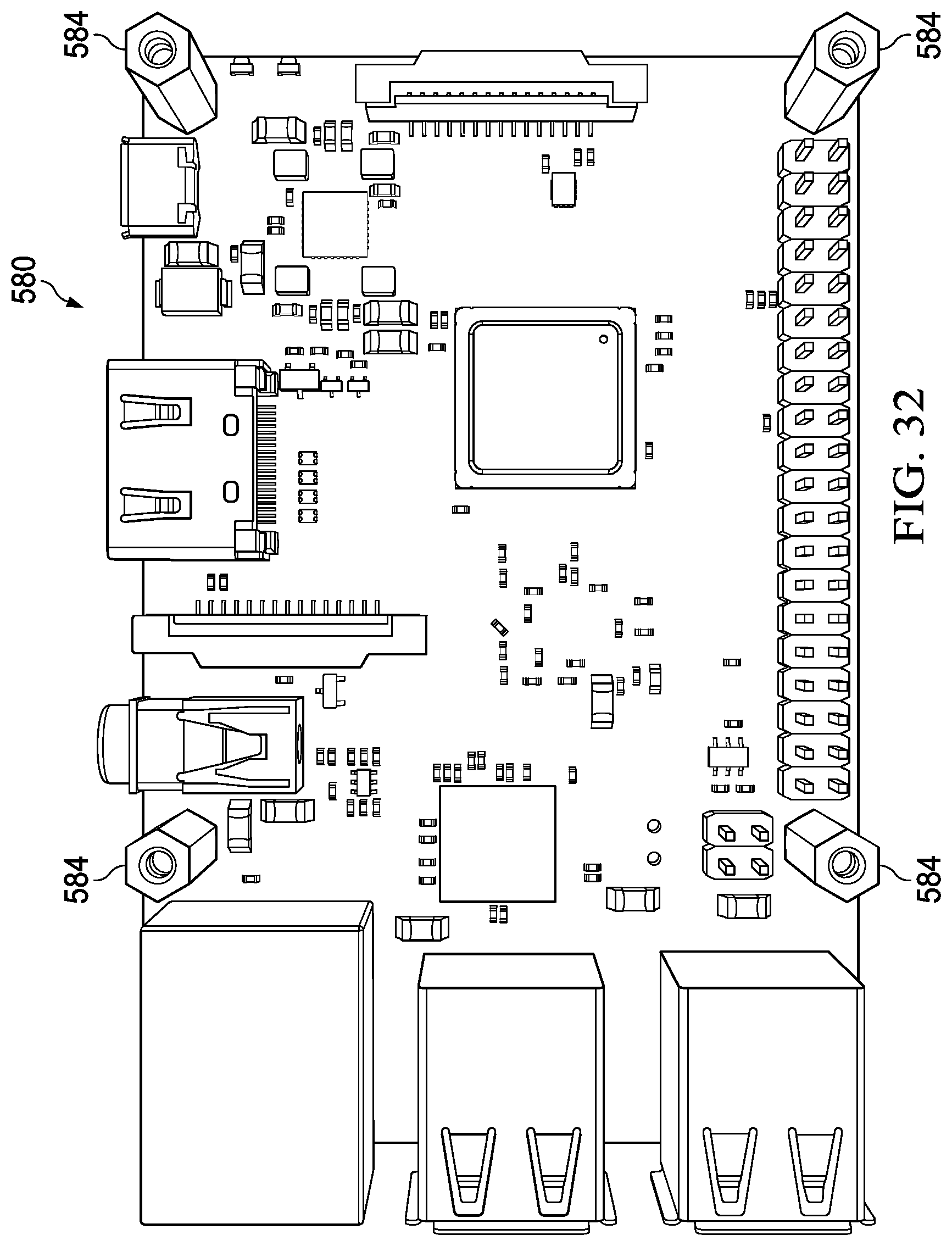
D00032

D00033

D00034

D00035
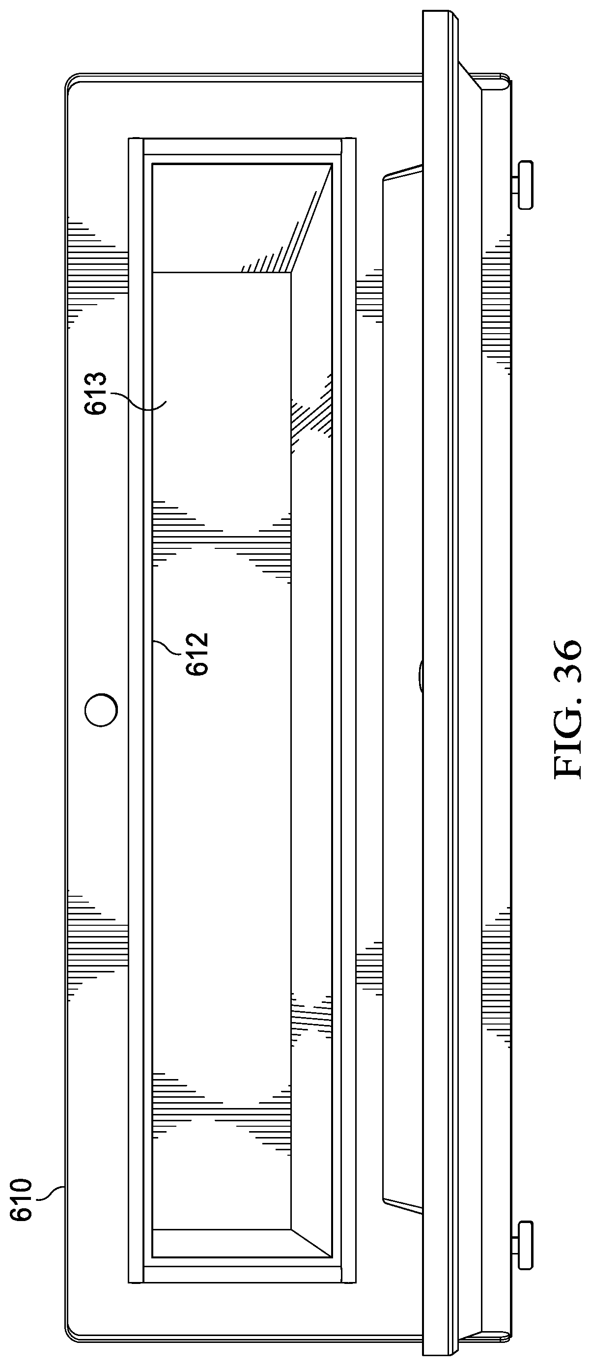
D00036
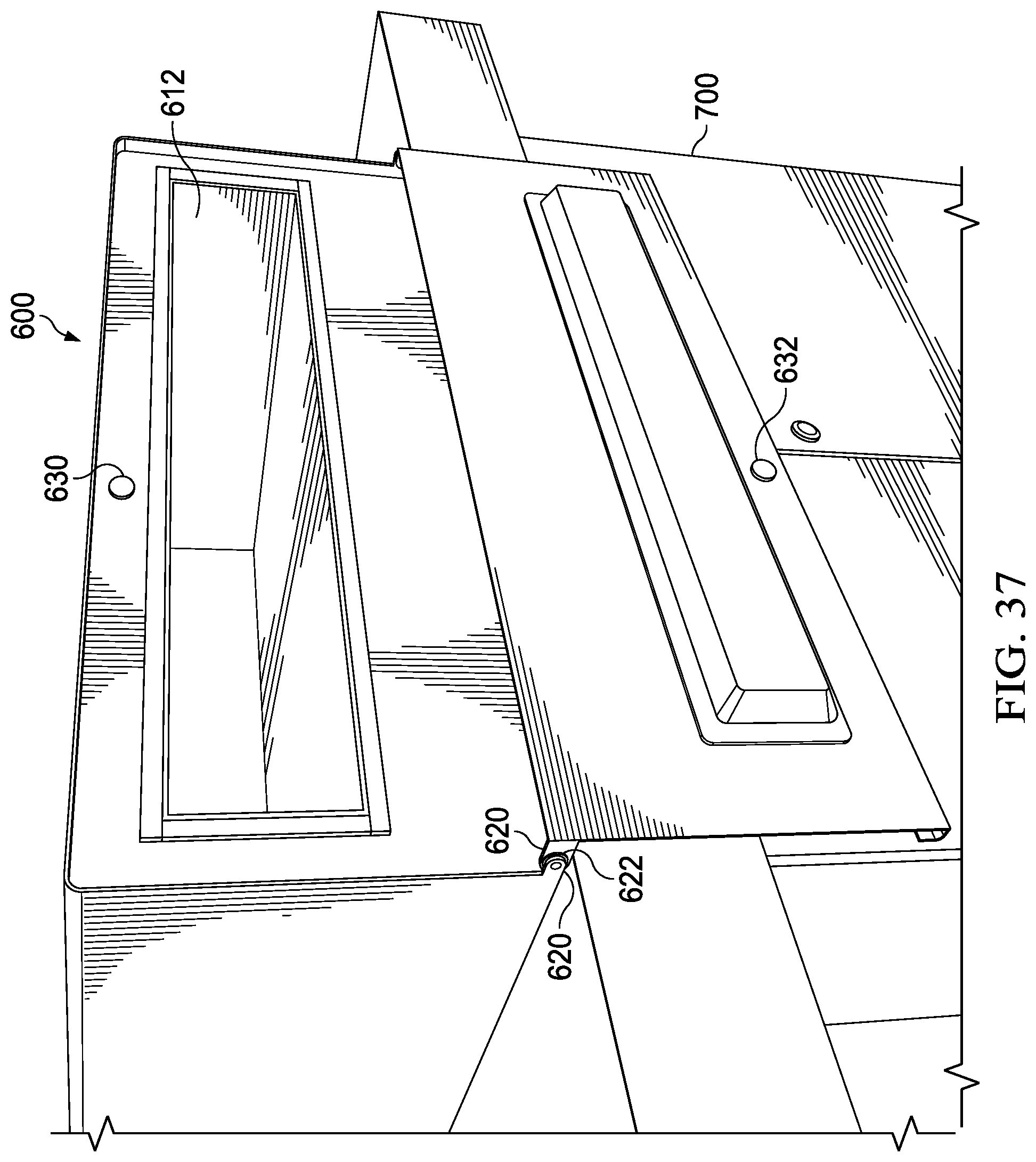
D00037
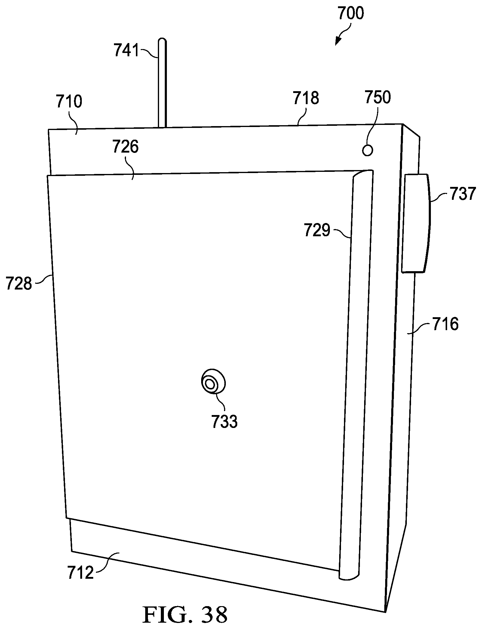
D00038

D00039
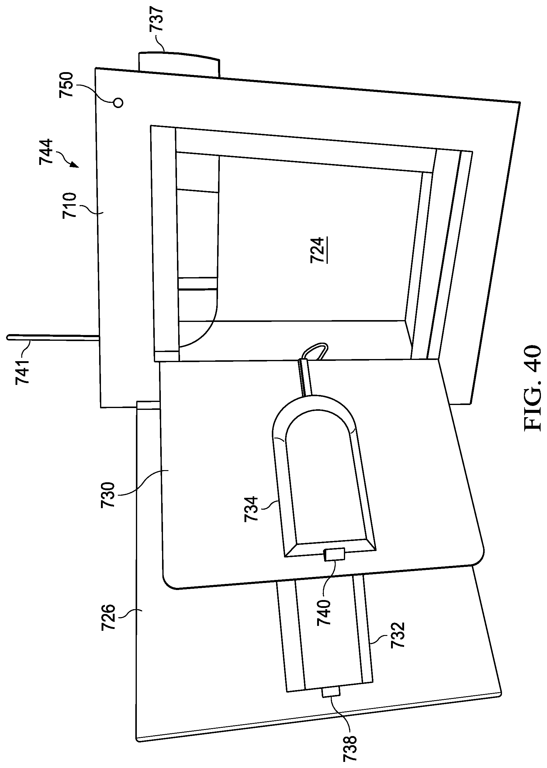
D00040
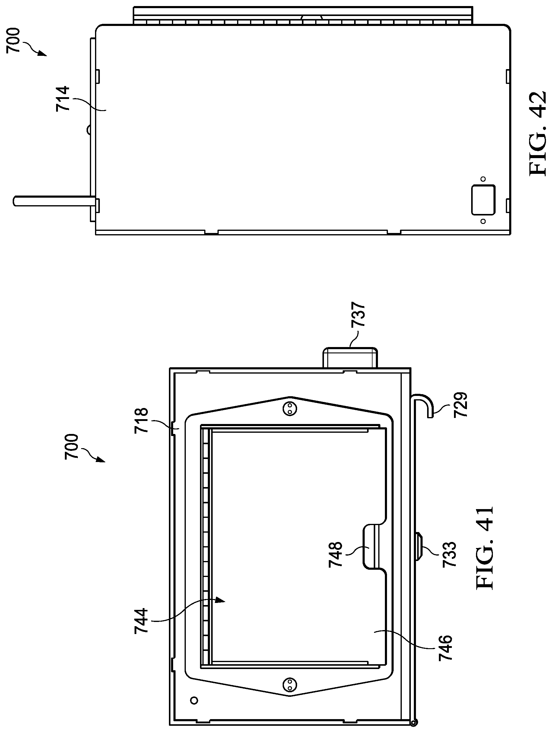
D00041
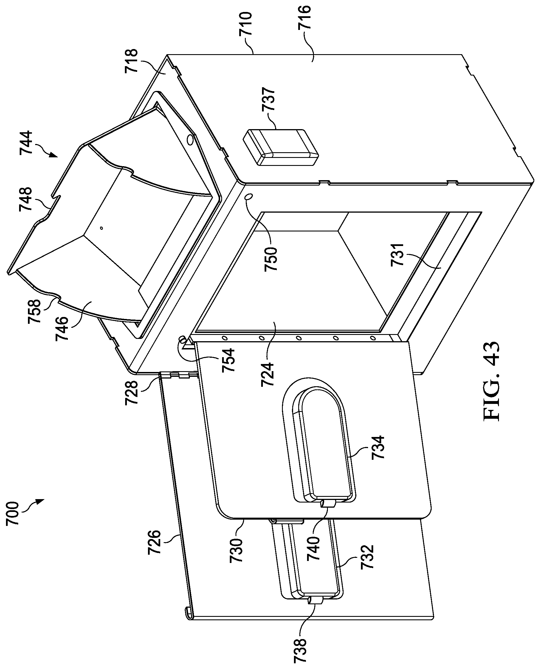
D00042

D00043
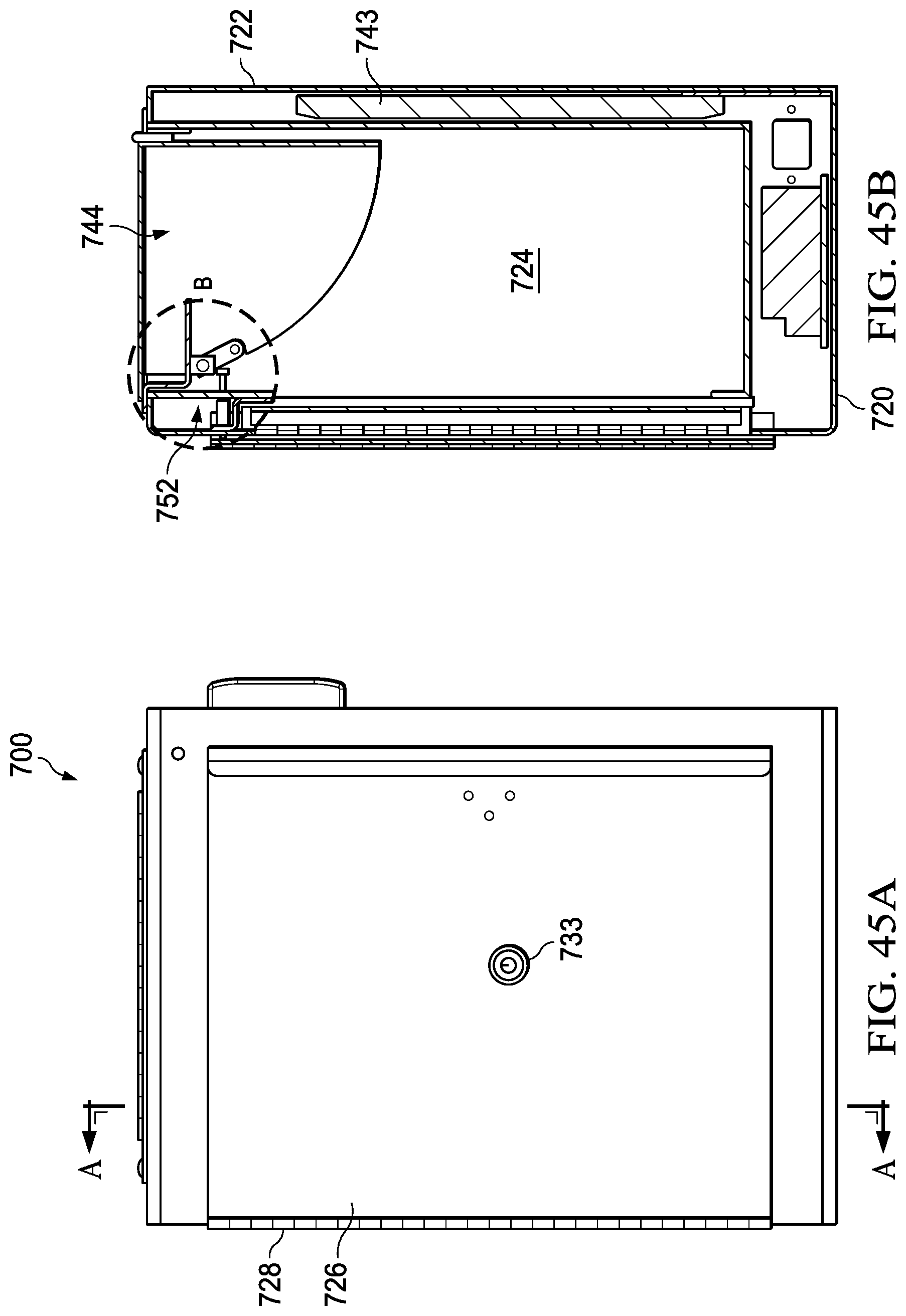
D00044
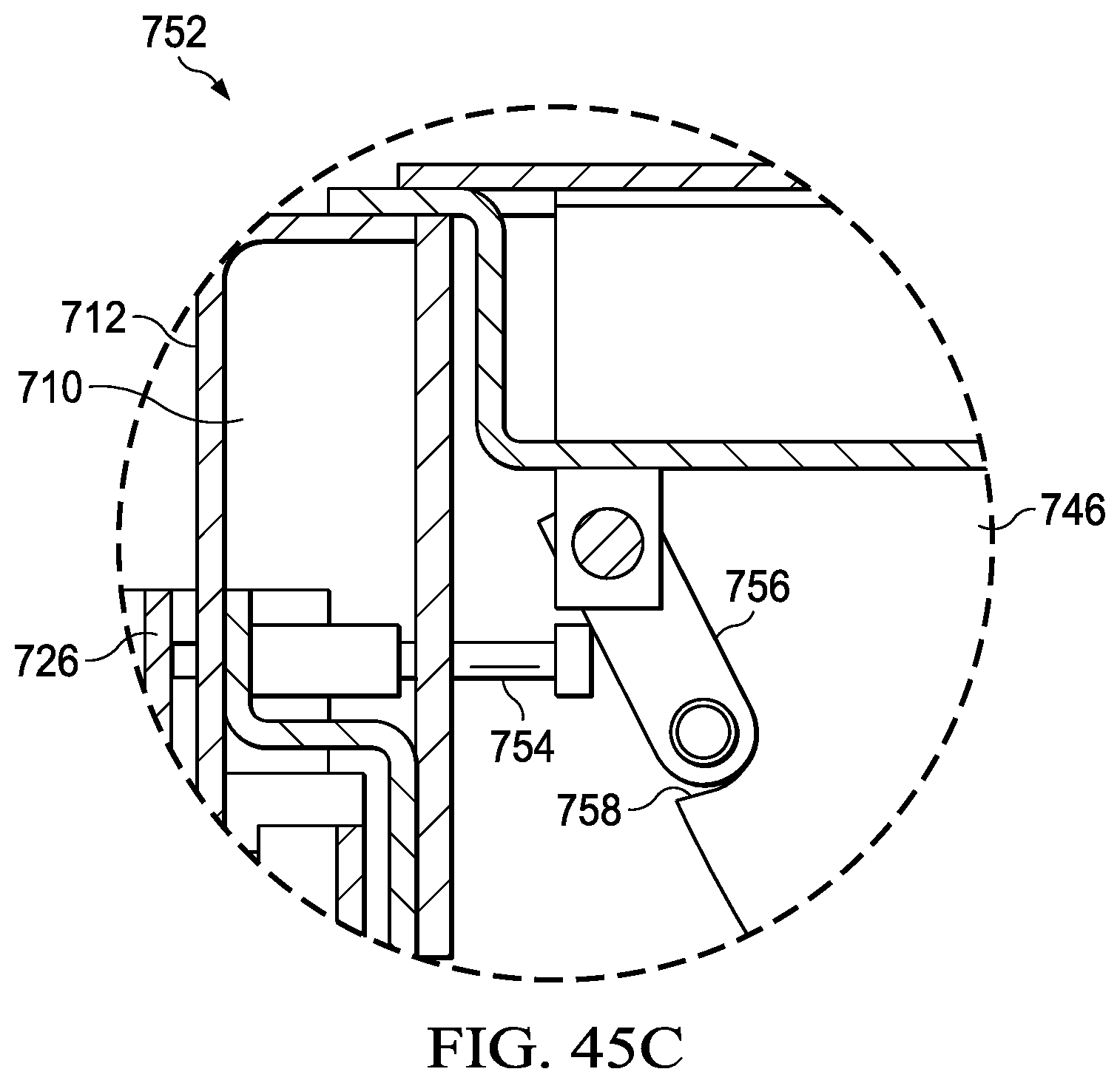
D00045
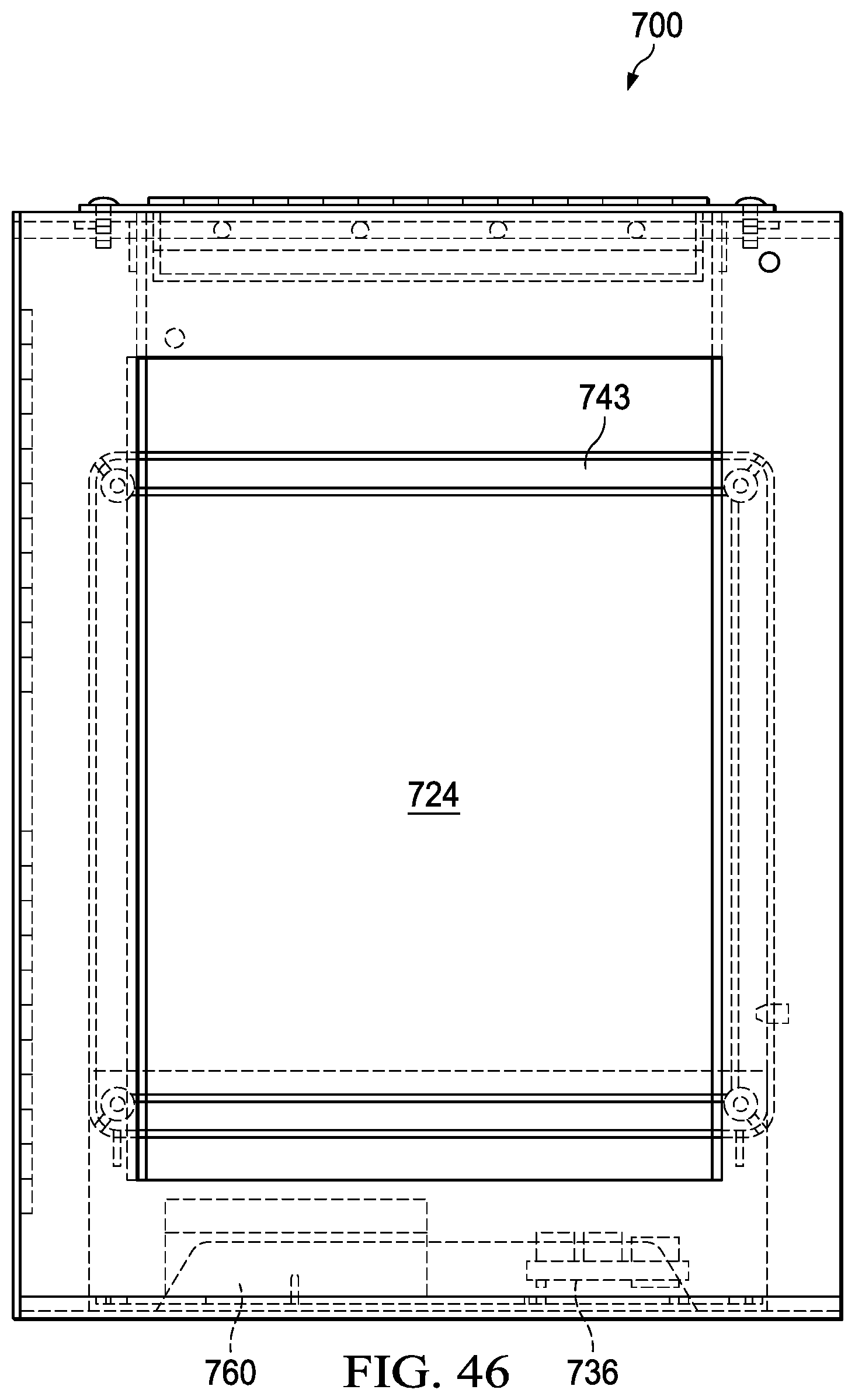
XML
uspto.report is an independent third-party trademark research tool that is not affiliated, endorsed, or sponsored by the United States Patent and Trademark Office (USPTO) or any other governmental organization. The information provided by uspto.report is based on publicly available data at the time of writing and is intended for informational purposes only.
While we strive to provide accurate and up-to-date information, we do not guarantee the accuracy, completeness, reliability, or suitability of the information displayed on this site. The use of this site is at your own risk. Any reliance you place on such information is therefore strictly at your own risk.
All official trademark data, including owner information, should be verified by visiting the official USPTO website at www.uspto.gov. This site is not intended to replace professional legal advice and should not be used as a substitute for consulting with a legal professional who is knowledgeable about trademark law.