Kinematic rail mount for mounting a device on a firearm rail
Cosentino
U.S. patent number 10,690,449 [Application Number 15/984,945] was granted by the patent office on 2020-06-23 for kinematic rail mount for mounting a device on a firearm rail. This patent grant is currently assigned to Steiner eOptics, Inc.. The grantee listed for this patent is Steiner eOptics, Inc.. Invention is credited to Tim J. Cosentino.


View All Diagrams
| United States Patent | 10,690,449 |
| Cosentino | June 23, 2020 |
Kinematic rail mount for mounting a device on a firearm rail
Abstract
The present disclosure provides a rail mount for mounting a device on a rail. According to an embodiment, the mount comprises a frame having a length along a first direction, a width along a second direction, and a height along a third direction; a clamp operatively connected to the frame to be slidable along the second direction; an adjustment cam operatively connected to the frame to be rotatable around a first axis extending along the third direction; and a lever cam operatively connected to the adjustment cam to be rotatable around a second axis extending along the third direction. The lever cam is configured to translate a rotary force applied thereto into a linear force applied to the clamp along the second direction. The adjustment cam is configured to shift the second axis closer to or further from the frame along the second direction when the adjustment cam is rotated.
| Inventors: | Cosentino; Tim J. (Waitsfield, VT) | ||||||||||
|---|---|---|---|---|---|---|---|---|---|---|---|
| Applicant: |
|
||||||||||
| Assignee: | Steiner eOptics, Inc.
(Waitsfield, VT) |
||||||||||
| Family ID: | 62222512 | ||||||||||
| Appl. No.: | 15/984,945 | ||||||||||
| Filed: | May 21, 2018 |
Prior Publication Data
| Document Identifier | Publication Date | |
|---|---|---|
| US 20180340754 A1 | Nov 29, 2018 | |
Related U.S. Patent Documents
| Application Number | Filing Date | Patent Number | Issue Date | ||
|---|---|---|---|---|---|
| 62510124 | May 23, 2017 | ||||
| Current U.S. Class: | 1/1 |
| Current CPC Class: | F41G 11/003 (20130101) |
| Current International Class: | F41G 11/00 (20060101) |
| Field of Search: | ;42/124,125,126 |
References Cited [Referenced By]
U.S. Patent Documents
| 5155915 | October 1992 | Repa |
| 5375361 | December 1994 | Rustick |
| 7562485 | July 2009 | Newhall |
| 7614175 | November 2009 | Davis |
| 7685759 | March 2010 | Teetzel |
| 8201355 | June 2012 | Couture |
| 8393105 | March 2013 | Thummel |
| 8397421 | March 2013 | Ding |
| 8806796 | August 2014 | Clifton |
| 8931161 | January 2015 | Couture |
| 9395158 | July 2016 | Collin |
| 9568281 | February 2017 | Chen |
| 9581416 | February 2017 | Yim et al. |
| 10024632 | July 2018 | Oglesby |
| 10036614 | July 2018 | Ruiz |
| 2008/0155876 | July 2008 | Matthews |
| 2008/0216380 | September 2008 | Teetzel |
| 2009/0000174 | January 2009 | Davis |
| 2009/0038201 | February 2009 | Cheng |
| 2010/0031553 | February 2010 | Couture |
| 2011/0146128 | June 2011 | Haering |
| 2011/0167701 | July 2011 | Williams |
| 2011/0247255 | October 2011 | Ding |
| 2011/0290968 | December 2011 | Maughan |
| 2013/0256484 | October 2013 | Kessler |
| 2013/0333184 | December 2013 | Couture et al. |
| 2014/0137457 | May 2014 | Collin |
| 2014/0196348 | July 2014 | Samson |
| 2014/0252187 | September 2014 | Petrovic |
| 2018/0259298 | September 2018 | Gao |
| 2018/0340754 | November 2018 | Cosentino |
| 2018/0340755 | November 2018 | Cosentino |
Other References
|
European Search Report, corresponding to EP18173583, dated Sep. 5, 2018, 1 page. cited by applicant . European Search Report, corresponding to EP18173573, dated Sep. 4, 2018, 1 page. cited by applicant. |
Primary Examiner: Morgan; Derrick R
Attorney, Agent or Firm: Innovation Counsel LLP
Parent Case Text
CROSS REFERENCE TO RELATED APPLICATIONS
This application claims benefit of priority to U.S. Provisional Patent Application No. 62/510,124 titled "A KINEMATIC RAIL MOUNT FOR MOUNTING A DEVICE ON A FIREARM RAIL" and filed May 23, 2017, which is incorporated herein by reference in its entirety.
Claims
What is claimed is:
1. A rail mount for mounting a device on a rail, the mount comprising: a frame having a length along a first direction, a width along a second direction, and a height along a third direction; a clamp operatively connected to the frame to be slidable with respect to the frame along the second direction to clamp the mount to the rail; an adjustment cam operatively connected to the frame to be rotatable around a first axis extending along the third direction; and a lever cam operatively connected to the adjustment cam to be rotatable around a second axis extending along the third direction, wherein the lever cam is configured to translate a rotary force applied thereto into a linear force applied to the clamp along the second direction, and wherein the adjustment cam is configured to shift the second axis closer to or further from the frame along the second direction when the adjustment cam is rotated around the first axis.
2. The rail mount of claim 1, wherein: the frame has a first end portion and a second end portion arranged along the first direction and an intermediate portion disposed between the first and second end portions, and the clamp includes a guide disposed in a channel formed in the intermediate portion of the frame.
3. The rail mount of claim 1, wherein the clamp is configured as a cam follower to the lever cam such that: rotation of the lever cam in one direction pushes the clamp towards a first edge of the frame, and rotation of the lever cam in an opposite direction allows the clamp to retract towards a second edge of the frame, the first and second edges being opposing edges extending along the first direction.
4. The rail mount of claim 3, wherein a retraction force of the clamp is provided by a return spring connected to the clamp.
5. The rail mount of claim 1, wherein: the adjustment cam is an eccentric cam having a first portion and a second portion that are non-concentric with each other, the frame includes a first bore, the lever cam includes a second bore, the first portion of the adjustment cam is inserted through the first bore, the second portion of the adjustment cam is inserted through the second bore, the first axis passes through both a center of the first bore and a center of the first portion of the adjustment cam, and the second axis passes through both a center of the second bore and a center of the second portion of the adjustment cam.
6. The rail mount of claim 5, further comprising a knob operatively connected to the adjustment cam and configured to rotate the adjustment cam with respect to the frame when the knob is rotated.
7. The rail mount of claim 6, wherein the knob is integrally formed with the adjustment cam.
8. The rail mount of claim 6, wherein the knob includes a protrusion and is configured to maintain the angular position of the adjustment cam with respect to the frame by interlocking the protrusion with one or more of a plurality of regularly-spaced grooves in the frame.
9. The rail mount of claim 8, further comprising: a release button operatively connected to the adjustment cam, and a compression spring configured to provide an interlocking force that maintains interlock between the protrusion and the one or more regularly-spaced grooves, wherein the release button is configured to disengage the interlock between the protrusion and the one or more regularly-spaced grooves while the release button is pressed.
10. The rail mount of claim 9, wherein: the knob and the release button are disposed on opposite ends of the adjustment cam, and the compression spring is disposed coaxially with the second portion of the adjustment cam between the release button and the frame to provide the interlocking force.
11. The rail mount of claim 6, wherein: the first portion of the adjustment cam has a male taper profile, and the first bore of the frame has a corresponding female taper profile for mating with the first portion of the adjustment cam.
12. The rail mount of claim 11, further comprising: a release button operatively connected to the adjustment cam, and a compression spring configured to maintain a frictional interface between the male and female taper profiles, wherein the release button is configured to disengage the frictional interface between the male and female taper profiles while the release button is pressed.
13. The rail mount of claim 12, wherein: the knob and the release button are disposed on opposite ends of the adjustment cam, and the compression spring is disposed coaxially with the second portion of the adjustment cam between the release button and the frame to maintain the frictional interface between the male and female taper profiles.
14. The rail mount of claim 6 wherein the adjustment cam comprises radially arranged detents, comprising one or more pins or balls arranged to engage the detents and exert a lateral force on the adjustment cam to maintain the angular position of the adjustment cam with respect to the frame.
15. The rail mount of claim 14, wherein the one or more pins or balls are spring pins or components of spring pins, the detents have a tapered profile, and rotation of the knob overcomes the lateral forces exerted by the one or more spring-pins on the adjustment cam to rotate the adjustment cam to a different angular position and shift the one or more spring-pins into different detents.
16. The rail mount of claim 14, wherein the one or more pins are or one or more spring-loaded locking pins, the detents have a square profile, and the one or more spring-loaded locking pins must be retracted from the detents before the knob is rotated to rotate the adjustment cam to a different angular position.
Description
RELATED FIELD
The present disclosure relates to a mount for mounting a device on a firearm rail.
BACKGROUND
Firearms have been around a long time, and their designs have evolved greatly and continue to evolve. One aspect of this evolution is that modern firearms have become more modular. For example, many modern firearms include an accessory rail on which various devices, such as a telescopic sight, a holographic sight, a laser sight, a flashlight, etc., may be mounted. While there are many existing mounts for mounting a device on an accessory rail, these existing mounts generally suffer from several drawbacks outlined below.
Typically, when a new sight is first mounted on a firearm, the point of aim of the sight would need to be adjusted to match the point of impact of the firearm. This process is generally known as "zeroing" the sight, which can be an arduous task for most shooters. However, because different sights offer different advantages, a shooter may want to swap out the sights after zeroing. Thus, it is desirable for the sight to maintain its point of aim, or "return to zero," despite repetitions of un-mounting and re-mounting the sight. Unfortunately, with many of the existing mounts, the point of aim of the mounted sight tends to shift between repetitions of un-mounting and re-mounting due to the over constrained clamping mechanism utilized by these mounts.
Furthermore, many of the existing mounts have either no adjustment mechanism for tuning its clamping force, use springs to compensate, or have tool actuated adjusters. A mount that does not offer clamping force adjustment may be mounted on too tightly or too loosely due to manufacturing variations in rail geometry. A mount that uses a spring to compensate for variations in rail geometry may produce soft clamping and thus may not be ideal for heavy payloads, since the mount would need a spring soft enough to be compressed by a hand-actuated lever but stiff enough to hold the mount in position under firearm recoil. A mount that requires a tool for tuning its clamping force would force the shooter to carry the correct tool for making field adjustments, thereby inconveniencing the shooter.
Embodiments of the present disclosure substantially overcome the above-discussed drawbacks of existing mounts for a mounting device on a firearm rail.
SUMMARY
The present disclosure provides a rail mount for mounting a device on a rail. According to an embodiment, the mount comprises a frame having a length along a first direction, a width along a second direction, and a height along a third direction; a clamp operatively connected to the frame to be slidable along the second direction to clamp the mount to the rail; an adjustment cam operatively connected to the frame to be rotatable around a first axis extending along the third direction; and a lever cam operatively connected to the adjustment cam to be rotatable around a second axis extending along the third direction, wherein the lever cam is configured to translate a rotary force applied thereto into a linear force applied to the clamp along the second direction, and wherein the adjustment cam is configured to shift the second axis closer to or further from the frame along the second direction when the adjustment cam is rotated around the first axis.
BRIEF DESCRIPTION OF THE DRAWINGS
The accompanying drawings, which are included as part of the present disclosure, illustrate various embodiments and together with the general description given above and the detailed description of the various embodiments given below serve to explain and teach the principles described herein.
FIG. 1 is a top view of a kinematic rail mount for mounting a device on a firearm rail, according to an embodiment of the present disclosure.
FIG. 2 is a bottom view of the same mount, according to an example embodiment of the present disclosure.
FIG. 3 shows an example of a firearm rail on which the mount may be mounted.
FIG. 4 shows an example of how the mount may be mounted onto the rail, according to an example embodiment.
FIG. 5 shows an exploded, bottom view of the mount, according to an example embodiment.
FIG. 6 shows a partial, exploded view of the mount detailing the frame and the clamp, according to an example embodiment.
FIG. 7 shows a partial, exploded view of the mount detailing the cam mechanism, according to an example embodiment.
FIG. 8 shows an example structure of the lever cam, according to an example embodiment.
FIG. 9 shows an example structure of the adjustment cam and knob, according to an example embodiment.
FIG. 10 shows another view of the adjustment cam taken along an axial direction, according to an example embodiment.
FIG. 11 shows a cross-sectional view of the mount when assembled, according to an example embodiment.
FIGS. 12a, 12b and 12c illustrate the distance of the lever cam with respect to the frame as the adjustment cam is rotated, according to an example embodiment.
FIG. 13 shows an example locking mechanism that prevents the knob from being unintentionally rotated, according to an embodiment.
FIG. 14 shows another example locking mechanism that prevents the knob from being unintentionally rotated, according to an embodiment.
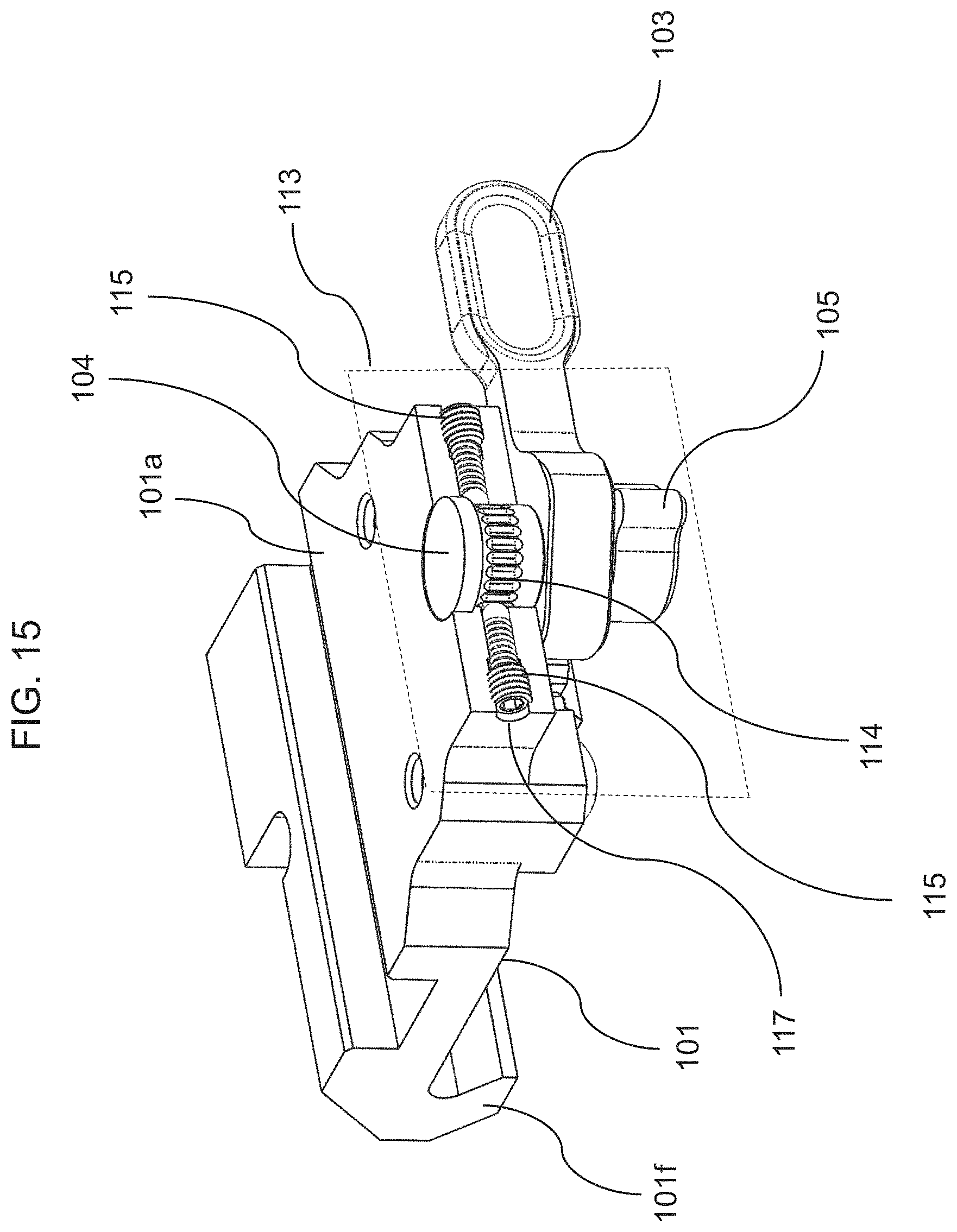
FIGS. 15 and 16 show another example locking mechanism that prevents the knob from being unintentionally rotated, according to an embodiment.
FIGS. 17 and 18 show example contact points on the rail at which the mount makes contact, according to an embodiment.
FIGS. 19 and 20 show example contact points on the mount that correspond to the contact points on the rail shown in FIGS. 17 and 18, according to an example embodiment.
FIG. 21 shows an alternative set of contact points on the rail at which the mount may make contact, according to another embodiment.
The figures in the drawings are not necessarily drawn to scale and elements of similar structures or functions are generally represented by like reference numerals for illustrative purposes throughout the figures. The figures are only intended to facilitate the description of the various embodiments described herein and do not describe every aspect of the teachings disclosed herein and do not limit the scope of the claims.
DETAILED DESCRIPTION
Each of the features and teachings disclosed herein may be utilized separately or in conjunction with other features and teachings to provide the present system and method. Representative examples utilizing many of these features and teachings, both separately and in combination, are described with reference to the attached figures. While the detailed description herein illustrates to a person of ordinary skill in the art further details for practicing aspects of the present teachings, it does not limit the scope of the claims. Therefore, combinations of features disclosed in the detailed description are representative examples of the present teachings and may not be necessary to practice the teachings in the broadest sense.
Relative terms, such as "top," "bottom," "left," "right," etc., may be used herein to describe the spatial relations of components shown in the figures. As such, when used in such context, these terms should be construed in accordance with the spatial orientation of the components as depicted in the relevant figures and not as absolute terms.
FIG. 1 is a top view of a kinematic rail mount for mounting a device on a firearm rail, and FIG. 2 is a bottom view of the same mount, according to an example embodiment of the present disclosure. The device, which is not shown, may, for example, be attached to a top surface 101a of the kinematic rail mount 100 (or just "mount" hereinafter for convenience), or a case for housing the device may be integrally formed with the mount 100.
FIG. 3 shows an example of a firearm rail on which the mount may be mounted, and FIG. 4 shows an example of how the mount may be mounted onto the rail, according to an example embodiment. The rail 300 shown in FIG. 3 is an example of a Picatinny rail (also known as MIL-STD-1913 rail) having a plurality of slots 301, a topmost surface 302 including angled edge portions 304, and an under surface 303 extending along opposing sides of the rail 300. In the illustrated embodiment, under surface 303 is angled with respect to the upper portion of topmost surface 302 and with respect to the angled edge portions 304 of topmost surface 302. The topmost surface 302, in this case, is discontinuously formed and interspersed by the slots 301 such that the topmost surface 302 includes a plurality of coplanar surfaces. As shown in FIG. 4 and discussed in further detail below, the mount 100 mounts to the rail 300 by way of a clamping mechanism that minimally contacts the topmost surface 302 and under surface 303 of the rail 300. In other variations mount 100 may be configured to mount to any other suitable firearm rail, such as for example a NATO rail.
FIG. 5 shows an exploded, bottom view of the mount, according to an example embodiment. The mount 100 includes a frame 101, a clamp 102, a lever cam 103, an adjustment cam 104, a knob 105, a release button 106, a release button spring 107, cam screws 108, guide brackets 109, an endplate bracket 110, bracket screws 111, and a clamp return spring 112. Although the embodiment of FIG. 5 shows many of the parts of the mount 100 as being separately formed and subsequently combined, one or more of the parts may be integrally formed. For example, instead of securing the brackets 109 and 110 using the bracket screws 101, the brackets 109 and 110 may be integrally formed with the frame 101, according to another embodiment. As another example, instead of securing the knob 105 to the adjustment cam 104 using one of the cam screws 108, the knob 105 may be integrally formed with the adjustment cam 104, according to another embodiment.
FIG. 6 shows a partial, exploded view of the mount detailing the frame and the clamp, according to an example embodiment. The frame 101 has a length along a first direction y, a width along a second direction x, and a height along a third direction z. A channel 101c is formed in a bottom surface 101b of the frame and extends along the second direction x. Raised pads 101d, which are elevated along the third direction z with respect to the bottom surface 101b, are formed in opposite end portions A and C (see also FIG. 2) of the frame 101 along the first direction y. In particular, the raised pads 101d are disposed closer to a first edge of the frame 101 extending along the first direction y than to an opposing, second edge of the frame 101. A raised pad 101e, which is also elevated along the third direction z with respect to the bottom surface 101b, is formed in an intermediate portion B and disposed closer to the opposing, second edge of the frame 101. The raised pad 101e may be disposed on opposing sides of the channel 101c.
The frame 101 also includes hook-shaped members 101f formed in opposite end portions A and C (see also FIG. 2) of the frame 101 along the first direction y. In particular, the hook-shaped members 101f are disposed closer to the first edge of the frame 101 extending along the first direction y than to the opposing, second edge of the frame 101. More about the function and configuration of the raised pads 101d and 101e and hook-shaped members 101f is discussed later on below.
The clamp 102 includes a guide portion 102a that is configured to be slidable in the channel 101c of the frame 101 and a hook-shaped member 102b disposed closer to the second edge of the frame 101 than to the first edge of the frame 101. Motion of the clamp 102 along the third direction z is constrained with respect to the frame 101 by guide brackets 109, which are secured to the frame 101 by bracket screws 111. While the clamp 102 is slidable in the channel 101c along the second direction, its range of motion may be limited by the endplate bracket 110, which is also secured to the frame 101 by bracket screws 111. For example, the endplate bracket 110 may include an endplate that prevents the clamp guide 102a from sliding and extending beyond the first edge of the frame 101. The clamp return spring 112 may be disposed between the endplate and an end of the clamp guide 102a to provide a return spring force that pushes the clamp 102a towards the second edge of the frame 101. More about the function and configuration of the hook-shaped member 102b and clamp return spring 112 is discussed later on below.
FIG. 7 shows a partial, exploded view of the mount detailing the cam mechanism, according to an example embodiment. FIG. 8 shows an example structure of the lever cam, and FIG. 9 shows an example structure of the adjustment cam and knob. FIG. 10 shows another view of the adjustment cam taken along the third direction z. The cam mechanism shown in FIG. 7 utilizes a cam-in-a-cam configuration that allows a user to fine-tune the maximum clamping force of the mount without the use of a tool, thereby overcoming an earlier-discussed drawback of existing mounts. The adjustment cam 104 is operatively connected to the frame 101 to be rotatable around a first axis a extending along the third direction z. The adjustment cam 104 is an eccentric cam and includes a first portion 104a and a second portion 104b that are non-concentric with each other. The first portion 104a of the adjustment cam 104 is inserted through and disposed within a first bore 101g formed in the frame 101. The first axis a passes through both a center of the first bore 101g and a center of the first portion 104a of the adjustment cam 104.
The lever cam 103 is operatively connected to the adjustment cam 104 to be rotatable around a second axis b extending along the third direction z. The second portion 104b of the adjustment cam 104 is inserted through and disposed within a second bore 103a formed in the lever cam 103. The second axis b passes through both a center of the second bore 103a and a center of the second portion 104b of the adjustment cam 104.
The adjustment cam 104, frame 101, and lever cam 103 are held together by the knob 105, which is operatively connected to the first portion 104a of the adjustment cam 104 via one of the cam screws 108, and by the release button 106, which is operatively connected to the second portion 104b of the adjustment cam 104 via another one of the cam screws 108. That is, the knob 105 and the release button 106 are disposed on opposite ends of the adjustment cam 104. The knob 105 is configured to rotate the adjustment cam 102 with respect to the frame 101 when the knob 105 is rotated. The release button spring 107 is disposed coaxially with the second portion 104b of the adjustment cam 104 between the release button 106 and the frame 101 to provide a spring force along the first and second axes a and b.
FIG. 11 shows a cross-sectional view of the mount when assembled, according to an example embodiment. In its assembled state, the clamp 102 acts as a cam follower to the lever cam 103. That is, when the lever cam 103 is rotated in one direction, it pushes the clamp 102 towards the first edge of the frame 101 along which the endplate bracket 110 is disposed. Thus, the lever cam 103 is configured to translate a rotary force applied thereto into a linear force applied to the clamp 102 along the second direction x. When the lever cam 103 is rotated in the other direction, it allows the clamp 102 to retract towards the second edge of the frame 101 via a spring force provided by the return spring 112.
FIGS. 12a, 12b and 12c illustrate the distance of the lever cam with respect to the frame as the adjustment cam is rotated, according to an example embodiment. As the adjustment cam 104 is rotated through its rotational range (e.g., 180 degrees), which is indicated by the angular position of the knob 105, the distance d between the frame 101 and the axis of rotation of the lever cam 103 is changed. This is because the lever cam 103 rotates around the second axis b, which passes through the center of the second portion 104b of the adjustment cam 104, and the second portion 104b of the adjustment cam 104 is non-concentric with the first portion 104a of the adjustment cam 104. Thus, when the first portion 104a of the adjustment cam 104 is rotated around the first axis a by the use of the knob 105, the position of the second axis b is shifted closer to or further from the frame 101 along the second direction x. Shifting the second axis b, and thereby the lever cam 103, closer to the frame 101 increases the maximum clamping force that can be applied against the rail, and vice versa. Accordingly, the cam-in-a-cam mechanism of the presently disclosed mount allows a user to fine-tune the maximum clamping force of the mount by adjusting the angular position of the knob 105 without the use of a tool, thereby overcoming an earlier-discussed drawback of existing mounts.
FIG. 13 shows an example locking mechanism that prevents the knob from being unintentionally rotated, according to an embodiment. The locking mechanism of FIG. 13 utilizes a plurality of regularly-spaced grooves 101h formed in the frame 101, for example, along a perimeter where the knob 105 is disposed. The knob 105 includes a protrusion 105a and is configured to maintain the angular position of the adjustment cam 104 with respect to the frame 101 by interlocking the protrusion 105a with one or more of the plurality of regularly-spaced grooves 101h in the frame 101. An interlocking force that keeps the protrusion 105a engaged or interlocked with the one or more regularly-spaced grooves 101h is provided by the release button spring 107 disposed between the release button 106 and the frame 101. While the release button 106 is pressed, thereby compressing the release button spring 107, the interlock between the protrusion 105a and the one or more regularly-formed grooves 101h is disengaged and the adjustment cam 104 may be rotated by rotating the knob 105. After the angular position of the knob 105 has been changed, the interlock may be reengaged by releasing the release button 106. Because the protrusion 105a interlocks with one or more of the grooves 101h, the angular position of the knob is set only in increments determined by the spacing of the grooves.
FIG. 14 shows another example locking mechanism that prevents the knob from being unintentionally rotated, according to an embodiment. According to this embodiment, the first portion 104a of the adjustment cam 104 has a male taper profile, and the first bore 101g of the frame 101 has a corresponding female taper profile for mating with the first portion 104a of the adjustment cam 104. A frictional interface between the tapered first portion 104a and the tapered first bore 101g is provided by the release button spring 107 disposed between the release button 106 and the frame 101. While the release button 106 is pressed, thereby compressing the release button spring 107, the frictional interface is disengaged and the adjustment cam 104 may be rotated by rotating the knob 105. The locking mechanism of FIG. 14 utilizes friction between two tapered profile surfaces to maintain the angular position of the knob 105 with respect to the frame 101, rather than the interlock shown in FIG. 13. Therefore, in the embodiment of FIG. 14, the angular position of the knob 105 can be adjusted in any increment.
In the variations shown in FIG. 13 and FIG. 14, the locking mechanism relies on an interlocking force that is directed axially along the adjustment cam 104 to engage protrusions 105a in grooves 101h (FIG. 13) or to engage tapered adjustment cam portion 104a in tapered first bore 101g of frame 101 (FIG. 14). In contrast, in the variation shown in FIG. 15 and FIG. 16, the locking mechanism relies on an interlocking force that is directed laterally (e.g., perpendicularly) against the adjustment cam to secure the adjustment cam in a selected orientation.
In the side perspective view shown in FIG. 15, a portion of frame 101 is removed at cut plane 113 (oriented perpendicularly to surface 101a of frame 101) to expose a locking mechanism comprising adjustment cam 104 and laterally oriented spring pins 115. In the upper perspective view shown in FIG. 16, portions of frame 101, adjustment cam 104, and spring pins 115 are removed at cut plane 118 (oriented parallel to surface 101a of frame 101) to provide a cross-sectional view of the locking mechanism.
In the variation illustrated in FIG. 15 and FIG. 16, adjustment cam 104 has the form of a king pin cam comprising radial tapered detents (ramps) 114. One or more spring pins 115 are arranged in (optionally threaded) holes 117 so that their inner ends engage detents 114 on adjustment cam 104 to exert a lateral force that prevents adjustment cam 104 from rotating freely. (The inner end of a spring pin may be or comprise a pin or a ball, for example). Adjustment cam 104 may be rotated about its long axis as described below but, in contrast to the variations of FIG. 13 and FIG. 14, it does not translate along its long axis.
The interlocking lateral forces exerted by the spring pins on the tapered detents on adjustment cam 104 may be overcome by exerting a sufficient rotational force on knob 105, which in this case functions as a lever on the king pin, to rotate the adjustment cam to a new position at which the spring pins will again engage detents 114 to retain the adjustment cam in its new radial orientation. As the rotational force is exerted on knob 105, the spring pins ride up the ramped walls of the tapered detents and then descend the tapered walls of adjacent detents.
Alternatively, detents 114 may be square edged locking detents and pins 115 may be spring-loaded locking pins. In such variations the spring-loaded locking pins may be retracted to disengage their ends from the detents to allow rotation of adjustment cam 104 to a new detent position.
Although the illustrated variation shows the use of two oppositely positioned pins 115, other variations may use only one pin or more than two pins, and the pins may be laterally arranged around adjustment cam 104 in any suitable manner.
As discussed earlier, another drawback of existing mounts is that, when mounting a sight, they may not always return the sight to zero due to their over constraining clamping mechanism. Existing mounts are generally designed to clamp against the surfaces of the rail using long, thin surfaces. However, due to inherent manufacturing tolerances, these long, thin surfaces of the mount, as well as the surfaces of the rail, are often not exactly flat, parallel, or angled to specification. These imperfections prevent the parts from fitting together exactly and may cause damage to the rail resulting in burrs and dings. For example, when these imperfect long, thin surfaces of the mount are clamped against the surfaces of the rail, an excessive number of contact points may be generated, resulting in an over constrained system. This means that the resting position between the mount and clamped rail becomes non-deterministic and elastically averaged. Thus, each time the mount is un-mounted and re-mounted, the resting position of the mount may slightly differ.
In contrast, the mount according to embodiments of the present disclosure provides a deterministic, or significantly more deterministic, resting position between the mount and rail by minimizing the number of intentional and unintentional contact points between the mount and the rail, thereby approaching that of a true kinematic rail mounting system. FIGS. 17 and 18 show example contact points on the rail at which the mount makes contact, according to an embodiment. FIGS. 19 and 20 show example contact points on the mount that correspond to the contact points on the rail, according to an example embodiment. The first set of contact areas 302a and 302b on the upper portion of topmost surface 302 of the rail 300 forms a stable triangle platform (i.e., determines a primary plane) at the furthest extents of the mount, thereby restraining the system (e.g., mount+rail) in 3 degrees of freedom (DOF). According to this embodiment, the frame 101 only contacts the topmost surface of the rail 300 by only the raised pads 101d and 101e (refer back to FIG. 6). In particular, the contact areas 302a are contacted by the raised pads 101d of the frame 101, and the contact area 302b is contacted by the raised pad 101e of the frame 101. Surfaces of the raised pads 101d and 101e contacting the topmost surface 302 of the rail 300 are formed to be discontinuous with each other to minimize the size of the contact areas with the rail. These small contact areas provide a more deterministic restraining solution approaching that of a perfectly constrained system.
A second set of contact areas 303a on the under surface 302 along one side of the rail 300 constrains the system in two more DOF (i.e., determines a line). The contact areas 303a are disposed adjacent to the contact areas 302a to face each other so as to reduce the degrees of freedom in the system. According to this embodiment, the frame 101 contacts the under surface along the one side of the rail 300 by only the hook-shaped members 101f (refer back to FIG. 6). Surfaces of the hooked-shaped members 101f contacting the under surface of the rail are formed to be discontinuous with each other, rather than forming one long continuous surface, to minimize the size of the contact areas with the rail. Again, these small contact areas provide a more deterministic restraining solution approaching that of a perfectly constrained system.
A last contact area 303b on the under surface 302 along an opposing side of the rail 300 constrains the system in another DOF (i.e., determines a point). The contact area 303b is disposed adjacent to the contact area 302b to face each other so as to reduce the amount of flex in the system, that is, to increase the stiffness of the system. According to this embodiment, the mount contacts the under surface along the opposing side of the rail 300 by only the hook-shaped member 102b (refer back to FIG. 6) of the clamp 102. When actuated by the lever cam 103, the clamp 102 forces the rail 300 up against the other 5 contact areas and by friction, constrains the mount to the rail 300, thereby removing the last DOF.
Referring again to FIG. 6, according to another embodiment raised pads 101d and 101e, hook shaped members 101f, and/or hooked shaped member 102b of clamp 102 comprise curved (e.g., large radius spherical) surfaces where they make contact with the rail. Some, all, or any combination of these features may comprise such curved surfaces. This way, the curved (e.g., spherical) contact area (or patch) between the flat surface (rail) and the curved surface (mount) becomes smaller. As the contact patch becomes smaller, the system approaches that of a true kinematic mounting system (e.g., point contact on a flat surface). Also, the contact patch (spherical surface) may be sized (radius) to limit the Hertzian stresses in the material.
Referring now to FIG. 21, in another embodiment the mount may be configured to make contact with the topmost surface of the rail at three points 304a and 304b located on angled edge portions 304 of topmost surface 302. The set of contact areas 304a and 304b forms a stable triangle platform (i.e., determines a primary plane) at the furthest extents of the mount, thereby restraining the system (e.g., mount+rail) in 3 degrees of freedom (DOF) similarly to the set of contact areas 303a and 303b shown in FIGS. 17 and 18.
In summary, the mount according to example embodiments disclosed herein provides at least two advantages over existing mounts. First, the presently disclosed mount includes a cam-in-a-cam clamping mechanism that allows a user to fine-tune the maximum clamping force of the mount without the use of a tool. Second, the presently disclosed mount provides a deterministic, or significantly more deterministic, resting position between the mount and rail by minimizing the number of intentional and unintentional contact points between the mount and the rail, thereby approaching that of a true kinematic mounting system that is significantly better suited for mounting a sight on a firearm.
The various features of the representative examples and the dependent claims may be combined in ways that are not specifically and explicitly enumerated in order to provide additional embodiments of the present teachings. The dimensions and the shapes of the components shown in the figures are designed to help understand how the present teachings are practiced and do not limit the dimensions and the shapes shown in the examples.
* * * * *
D00000
D00001
D00002
D00003
D00004
D00005
D00006
D00007
D00008
D00009
D00010
D00011
D00012

D00013

D00014

D00015

D00016

XML
uspto.report is an independent third-party trademark research tool that is not affiliated, endorsed, or sponsored by the United States Patent and Trademark Office (USPTO) or any other governmental organization. The information provided by uspto.report is based on publicly available data at the time of writing and is intended for informational purposes only.
While we strive to provide accurate and up-to-date information, we do not guarantee the accuracy, completeness, reliability, or suitability of the information displayed on this site. The use of this site is at your own risk. Any reliance you place on such information is therefore strictly at your own risk.
All official trademark data, including owner information, should be verified by visiting the official USPTO website at www.uspto.gov. This site is not intended to replace professional legal advice and should not be used as a substitute for consulting with a legal professional who is knowledgeable about trademark law.