Cartridge insertion assembly
Cabiri
U.S. patent number 10,688,243 [Application Number 15/395,166] was granted by the patent office on 2020-06-23 for cartridge insertion assembly. This patent grant is currently assigned to WEST PHARMA. SERVICES IL, LTD.. The grantee listed for this patent is West Pharma. Services IL, Ltd.. Invention is credited to Oz Cabiri.


View All Diagrams
| United States Patent | 10,688,243 |
| Cabiri | June 23, 2020 |
Cartridge insertion assembly
Abstract
A cartridge insertion assembly including apparatus with a pathway formed therein, a cartridge including a cartridge coupling element connectable to an activation mechanism disposed in the apparatus operative to cause a substance contained in the cartridge to be metered out of the cartridge, and a door pivoted to the apparatus that includes a door coupling element arranged with respect to the cartridge such that when the door is in a fully closed position, the door coupling element couples the cartridge coupling element with a coupling element of the activation mechanism.
| Inventors: | Cabiri; Oz (Macabim-Reut, IL) | ||||||||||
|---|---|---|---|---|---|---|---|---|---|---|---|
| Applicant: |
|
||||||||||
| Assignee: | WEST PHARMA. SERVICES IL, LTD.
(Ra'anana, IL) |
||||||||||
| Family ID: | 43355552 | ||||||||||
| Appl. No.: | 15/395,166 | ||||||||||
| Filed: | December 30, 2016 |
Prior Publication Data
| Document Identifier | Publication Date | |
|---|---|---|
| US 20170106138 A1 | Apr 20, 2017 | |
Related U.S. Patent Documents
| Application Number | Filing Date | Patent Number | Issue Date | ||
|---|---|---|---|---|---|
| 13892905 | May 13, 2013 | 9572926 | |||
| 13272555 | Oct 13, 2011 | 8465455 | |||
| 12559563 | Sep 15, 2009 | 8157769 | |||
| Current U.S. Class: | 1/1 |
| Current CPC Class: | A61M 5/1456 (20130101); A61M 5/158 (20130101); A61M 5/14248 (20130101); A61M 5/162 (20130101); A61M 2005/14573 (20130101); A61M 2005/14268 (20130101) |
| Current International Class: | A61M 5/145 (20060101); A61M 5/162 (20060101); A61M 5/158 (20060101); A61M 5/142 (20060101) |
References Cited [Referenced By]
U.S. Patent Documents
| 4300554 | November 1981 | Hessberg et al. |
| 4689043 | August 1987 | Bisha |
| 5090877 | February 1992 | D'Silva |
| 5364364 | November 1994 | Kasvikis et al. |
| 5445621 | August 1995 | Poli et al. |
| 5505709 | April 1996 | Funderburk et al. |
| D372098 | July 1996 | Lattin et al. |
| D384745 | October 1997 | Lattin et al. |
| 5779676 | July 1998 | Kriesel et al. |
| 5820406 | October 1998 | Hetherington |
| 5830187 | November 1998 | Kriesel et al. |
| 5858001 | January 1999 | Tsals et al. |
| 5954697 | September 1999 | Srisathapat et al. |
| 6117575 | September 2000 | Dinsdale |
| 6160487 | December 2000 | DeLuca |
| 6305908 | October 2001 | Hermann et al. |
| 6423036 | July 2002 | Van Huizen |
| 6599272 | July 2003 | Hjertman et al. |
| 7569050 | August 2009 | Moberg et al. |
| 7588559 | September 2009 | Aravena et al. |
| D602155 | October 2009 | Foley et al. |
| 7749194 | July 2010 | Edwards et al. |
| 7806868 | October 2010 | De Polo et al. |
| 7967795 | June 2011 | Cabiri |
| 8157769 | April 2012 | Cabiri |
| D685083 | June 2013 | Schneider et al. |
| 8465455 | June 2013 | Cabiri |
| D687141 | July 2013 | Schneider et al. |
| D687536 | August 2013 | Guarraia et al. |
| D723157 | February 2015 | Clemente et al. |
| D768288 | October 2016 | O'Connor et al. |
| D774640 | December 2016 | Tyce et al. |
| D776262 | January 2017 | Tyce et al. |
| D776263 | January 2017 | Tyce et al. |
| D776264 | January 2017 | Tyce et al. |
| D776265 | January 2017 | Tyce et al. |
| 9707335 | July 2017 | Agard et al. |
| D794776 | August 2017 | Tyce et al. |
| 9737655 | August 2017 | Clemente et al. |
| 9782545 | October 2017 | Gross et al. |
| 9802030 | October 2017 | Clemente et al. |
| D804019 | November 2017 | Costello et al. |
| 9814832 | November 2017 | Agard et al. |
| D804650 | December 2017 | Costello et al. |
| D805186 | December 2017 | Costello et al. |
| D805187 | December 2017 | Costello et al. |
| D805188 | December 2017 | Costello et al. |
| D805189 | December 2017 | Costello et al. |
| D805190 | December 2017 | Costello et al. |
| 9861759 | January 2018 | Gross et al. |
| D810278 | February 2018 | Cabiri et al. |
| D810279 | February 2018 | Cabiri et al. |
| D811583 | February 2018 | Cabiri et al. |
| D811584 | February 2018 | Cabiri et al. |
| 2003/0109827 | June 2003 | Lavi et al. |
| 2004/0015131 | January 2004 | Flaherty et al. |
| 2004/0064088 | April 2004 | Gorman et al. |
| 2005/0203461 | September 2005 | Flaherty et al. |
| 2006/0264831 | November 2006 | Skwarek et al. |
| 2007/0167912 | July 2007 | Causey et al. |
| 2007/0197968 | August 2007 | Pongpairochana |
| 2007/0219480 | September 2007 | Kamen et al. |
| 2008/0097381 | April 2008 | Moberg et al. |
| 2008/0234627 | September 2008 | Dent et al. |
| 2008/0255516 | October 2008 | Yodfat |
| 2008/0281270 | November 2008 | Cross et al. |
| 2009/0093792 | April 2009 | Gross et al. |
| 2009/0093793 | April 2009 | Gross et al. |
| 2009/0105650 | April 2009 | Wiegel et al. |
| 2009/0131860 | May 2009 | Nielsen |
| 2009/0143735 | June 2009 | De Polo et al. |
| 2009/0243234 | October 2009 | Sharifi |
| 2010/0081993 | April 2010 | O'Connor |
| 2010/0168683 | July 2010 | Cabiri |
| 2010/0211011 | August 2010 | Haar |
| 2011/0066131 | March 2011 | Cabiri |
| 2011/0137239 | June 2011 | DeBelser et al. |
| 2012/0035546 | February 2012 | Cabiri |
| 2013/0060233 | March 2013 | O'Connor et al. |
| 2013/0296792 | November 2013 | Cabiri |
| 2014/0188073 | July 2014 | Cabiri et al. |
| 2015/0057613 | February 2015 | Clemente et al. |
| 2016/0058941 | March 2016 | Wu et al. |
| 2016/0256352 | September 2016 | Bar-El et al. |
| 2017/0028132 | February 2017 | Cronenberg et al. |
| 2017/0106138 | April 2017 | Cabiri |
| 2017/0224915 | August 2017 | Destefano et al. |
| 2017/0281859 | October 2017 | Agard et al. |
| 2017/0312450 | November 2017 | Gross et al. |
| 2017/0354781 | December 2017 | Cronenberg et al. |
| 2017/0354782 | December 2017 | Quinn et al. |
| 2017/0354783 | December 2017 | Gazeley et al. |
| 2017/0354785 | December 2017 | Gazeley et al. |
| 2017/0354788 | December 2017 | Quinn et al. |
| 2018/0001073 | January 2018 | Clemente et al. |
| 2018/0008769 | January 2018 | O'Connor et al. |
| 2018/0021508 | January 2018 | Destefano et al. |
| 2018/0028747 | February 2018 | Hanson et al. |
| 2018/0043091 | February 2018 | Agard et al. |
| 1408443 | Apr 2003 | CN | |||
| 101239205 | Aug 2008 | CN | |||
| 2698180 | Feb 2014 | EP | |||
| 2727617 | May 2014 | EP | |||
| 2009044401 | Apr 2009 | WO | |||
| 2011/034799 | Mar 2011 | WO | |||
| 2012032411 | Mar 2012 | WO | |||
| 2012160157 | Nov 2012 | WO | |||
| 2012160160 | Nov 2012 | WO | |||
| 2014/107408 | Jul 2014 | WO | |||
Other References
|
Office Action dated Jul. 13, 2011 in U.S. Appl. No. 12/559,563 by Cabiri. cited by applicant . Office Action dated Jul. 2, 2012 in U.S. Appl. No. No. 13/272,555 by Cabiri. cited by applicant . Office Action dated Jan. 4, 2016 in U.S. Appl. No. No. 13/892,905 by Cabiri. cited by applicant . Int'l Search Report and Written Opinion dated Dec. 1, 2011 in Int'l Application No. PCT/US2010/048556. cited by applicant . Int'l Preliminary Report on Patentability dated Jan. 9, 2011 in Int'l Application No. PCT/US2010/048556. cited by applicant . Office Action dated Sep. 29, 2013 in CN Application No. 201080040968.7. cited by applicant . Office Action dated Apr. 24, 2013 in CN Application No. 201080040968.7. cited by applicant . Search Report dated Apr. 24, 2013 in CN Application No. 201080040968.7. cited by applicant . Office Action dated Jul. 29, 2013 in JP Application No. 2012-529808. cited by applicant . Office Action dated Dec. 17, 2013 in JP Application No. 2012-529808. cited by applicant . Office Action dated Nov. 16, 2015 in U.S. Appl. No. 13/733,516 by Cabiri. cited by applicant . Int'l Search Report and Written Opinion dated Apr. 3, 2014 in Int'l Application No. PCT/US2013/078040. cited by applicant . Int'l Preliminary Report on Patentability dated Jul. 16, 2015 in Int'l Application No. PCT/US2013/078040. cited by applicant . U.S. Appl. No. 15/196,775 by Cabiri, filed Jun. 29, 2016. cited by applicant . Office Action dated Jul. 7, 2016 in U.S. Appl. No. 13/892,905 by Cabiri. cited by applicant . Office Action dated Aug. 13, 2018 in IN Application No. 857/KOLNP/2012. cited by applicant . Office Action dated Mar. 15, 2018 in U.S. Appl. No. 29/628,592 by Cabiri. cited by applicant. |
Primary Examiner: Farrar; Lauren P
Assistant Examiner: Ponton; James D
Attorney, Agent or Firm: Panitch Schwarze Belisario & Nadel LLP
Parent Case Text
CROSS-REFERENCE TO RELATED APPLICATIONS
The present application is a continuation of U.S. patent application Ser. No. 13/892,905, filed May 13, 2013 and entitled CARTRIDGE INSERTION ASSEMBLY, which is a continuation of U.S. patent application Ser. No. 13/272,555, filed Oct. 13, 2011 and entitled CARTRIDGE INSERTION ASSEMBLY FOR DRUG DELIVERY SYSTEM and issued as U.S. Pat. No. 8,465,455, which is a continuation of U.S. patent application Ser. No. 12/559,563, filed on Sep. 15, 2009 and entitled "CARTRIDGE INSERTION ASSEMBLY FOR DRUG DELIVERY SYSTEM and issued as U.S. Pat. No. 8,157,769.
Claims
I claim:
1. A method of loading a cartridge containing a substance to be administered to a subject into an apparatus for administering the substance, the method comprising: moving a door of the apparatus into an open position thereof to expose a pathway within the apparatus; inserting the cartridge into the pathway, the cartridge comprising a cartridge coupling element and a septum at an end opposite to the cartridge coupling element, the cartridge coupling element being connectable to a coupling element of an activation mechanism disposed in the apparatus and operative to cause the substance in the cartridge to be metered out; and moving the door to a closed position, which couples a door coupling element with each of the cartridge coupling element and the activation mechanism coupling element, thereby coupling the cartridge coupling element with the activation mechanism coupling element.
2. The method of claim 1, wherein the inserting step further comprises abutting the cartridge against a cartridge stopper disposed in the apparatus when the cartridge is inserted into the pathway.
3. The method of claim 1, wherein the apparatus comprises a hollow needle disposed therein, and further comprising a step of puncturing the septum with the needle when the cartridge is inserted into the pathway.
4. The method of claim 1, wherein the door further comprises at least one rib and the apparatus further comprises a corresponding at least one groove, wherein the step of moving the door into the closed position includes inserting the at least one rib in the corresponding at least one groove.
5. The method of claim 1, wherein the door further comprises a closure member on an inside surface thereof, the closure member comprising a hub, wherein the step of moving the door into the closed position includes fixedly inserting the hub into a snap member of the apparatus.
6. The method of claim 1, wherein the apparatus further comprises a surface configured to adhere to skin of the subject.
7. A method of loading a cartridge containing a substance to be administered to a subject into an apparatus for administering the substance, the method comprising: moving a door of the apparatus into an open position thereof to expose a pathway within the apparatus; inserting the cartridge into the pathway, the cartridge comprising a cartridge coupling element connectable to a coupling element of an activation mechanism disposed in the apparatus and operative to cause the substance in the cartridge to be metered out; and moving the door to a closed position, wherein a door coupling element couples the cartridge coupling element with the activation mechanism coupling element, wherein the apparatus further comprises a locking latch cantilevered from a base thereof and the cartridge further comprises a rim proximate a rear end thereof, and wherein the inserting step further comprises depressing and sliding over and past the locking latch with the rim of the cartridge during insertion of the cartridge into the pathway whereby when the rim slides past the locking latch, the locking latch springs back and abuts against the rim, locking the cartridge into the pathway.
8. A method of loading a cartridge containing a substance to be administered to a subject into an apparatus for administering the substance, the method comprising: moving a door of the apparatus into an open position thereof to expose a pathway within the apparatus; inserting the cartridge into the pathway, the cartridge comprising a cartridge coupling element connectable to a coupling element of an activation mechanism disposed in the apparatus and operative to cause the substance in the cartridge to be metered out; and moving the door to a closed position, wherein a door coupling element couples the cartridge coupling element with the activation mechanism coupling element, wherein the door further comprises a closure member on an inside surface thereof, the closure member comprising at least one inclined ramp member, and wherein the step of moving the door into the closed position thereof includes sliding the at least one ramp member against the cartridge coupling element, pushing the cartridge into the apparatus.
9. A method of loading a cartridge containing a substance to be administered to a subject into an apparatus for administering the substance, the method comprising: moving a door of the apparatus into an open position thereof to expose a pathway within the apparatus; inserting the cartridge into the pathway, the cartridge comprising a cartridge coupling element connectable to a coupling element of an activation mechanism disposed in the apparatus and operative to cause the substance in the cartridge to be metered out; and moving the door to a closed position, wherein a door coupling element couples the cartridge coupling element with the activation mechanism coupling element, wherein the cartridge coupling element, the door coupling element, and the activation mechanism coupling element comprise gears.
10. A method of loading a cartridge containing a substance to be administered to a subject into an apparatus for administering the substance, the method comprising: moving a door of the apparatus into an open position thereof to expose a pathway within the apparatus; inserting the cartridge into the pathway, the cartridge comprising a cartridge coupling element connectable to a coupling element of an activation mechanism disposed in the apparatus and operative to cause the substance in the cartridge to be metered out; and moving the door to a closed position, which couples a door coupling element with each of the cartridge coupling element and the activation mechanism coupling element, thereby coupling the cartridge coupling element with the activation mechanism coupling element, wherein the door coupling element is sized and shaped to transmit rotary motion.
11. A method of loading a cartridge containing a substance to be administered to a subject into an apparatus for administering the substance, the method comprising: moving a door of the apparatus into an open position thereof to expose a pathway within the apparatus; inserting the cartridge into the pathway until a shoulder of the cartridge abuts against a cartridge stopper disposed in the apparatus, the cartridge comprising a cartridge coupling element connectable to a coupling element of an activation mechanism disposed in the apparatus and operative to cause the substance in the cartridge to be metered out; and moving the door to a closed position, which couples a door coupling element with each of the cartridge coupling element and the activation mechanism coupling element, thereby coupling the cartridge coupling element with the activation mechanism coupling element.
Description
The contents of all of the above applications are incorporated by reference in their entireties as if fully set forth herein.
BACKGROUND OF THE INVENTION
The present invention generally relates to drug delivery systems, e.g., external drug pumps, and particularly to an assembly for inserting a cartridge, which contains a substance to be administered to a patient, into the drug delivery system.
External drug pumps are typically used to deliver to patients substances which contain large molecules which cannot be digested when administered orally, such as insulin. Typically, the pump is adhered to the abdomen or chest or other of the patient and delivers the substance to the patient via a cannula that is inserted into the patient subcutaneously, although the invention described below is not limited to needle administration of substances.
BRIEF SUMMARY OF THE INVENTION
The present invention seeks to provide an improved assembly for inserting a cartridge, which contains a substance to be administered to a patient, into a drug pump (or any kind of drug delivery system), as is described more in detail hereinbelow. It is noted that the term "cartridge" encompasses any kind of reservoir or container (disposable or not) for a substance that is to be administered to a patient, such as but not limited to, a vial, ampoule, bottle, pre-filled syringe and the like, and is not limited to any size or shape.
There is thus provided in accordance with an embodiment of the present invention a cartridge insertion assembly including apparatus with a pathway formed therein, a cartridge insertable into the pathway, the cartridge including a cartridge coupling element connectable to an activation mechanism disposed in the apparatus operative to cause a substance contained in the cartridge to be metered out of the cartridge, and a door pivoted to the apparatus that includes a door coupling element arranged with respect to the cartridge such that when the door is in a fully closed position, the door coupling element couples the cartridge coupling element with a coupling element of the activation mechanism.
In accordance with an embodiment of the present invention a locking latch is cantilevered from a base of the apparatus, wherein when the cartridge is fully inserted in the apparatus, the locking latch abuts against a rim of the cartridge, thereby locking the cartridge in the pathway.
In accordance with an embodiment of the present invention when the cartridge is fully inserted in the apparatus, the cartridge abuts against a cartridge stopper disposed in the apparatus.
In accordance with an embodiment of the present invention the cartridge includes a septum at an end opposite to the cartridge coupling element, and the apparatus includes a hollow needle, wherein when the cartridge is fully inserted in the apparatus, the needle punctures the septum.
In accordance with an embodiment of the present invention the door includes a closure member on an inside surface thereof, the closure member including one or more inclined ramp members, wherein closing the door causes the ramp members to slide and push against the cartridge coupling element so as to push the cartridge fully into the apparatus.
In accordance with an embodiment of the present invention the door is formed with one or more ribs, which when the door is fully closed, the ribs are received in one or more corresponding grooves formed in the apparatus.
In accordance with an embodiment of the present invention the closure member includes a hub, wherein when the door is fully closed, the hub is fixedly received in a snap member.
BRIEF DESCRIPTION OF THE SEVERAL VIEWS OF THE DRAWINGS
The present invention will be understood and appreciated more fully from the following detailed description taken in conjunction with the drawings in which:
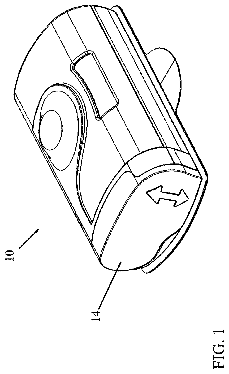
FIG. 1 is a simplified illustration of apparatus for administering a substance to a subject, in accordance with an embodiment of the present invention;
FIG. 2 is a simplified illustration of the apparatus of FIG. 1, showing a door of a cartridge insertion assembly in the open position and a cartridge poised for insertion into the apparatus;
FIG. 3 is a simplified illustration of the cartridge partially inserted into the apparatus;
FIG. 4 is a simplified illustration of the cartridge partially inserted into the apparatus, showing components of the cartridge insertion assembly;
FIG. 5 is a simplified illustration of the cartridge fully inserted into the apparatus up to a cartridge stopper of the cartridge insertion assembly, with the door still open;
FIG. 6 is a simplified illustration of the cartridge fully inserted into the apparatus and locked in place;
FIG. 7 is a simplified illustration of a locking latch that locks the cartridge in place;
FIG. 8 is a simplified illustration of the inside of the door of the cartridge insertion assembly;
FIG. 9 is a simplified illustration of partially closing the door of the cartridge insertion assembly;
FIG. 10 is a simplified illustration of the door fully closed, but only showing the inner components of the door (e.g., coupling elements) and not the outside surface of the door itself; and
FIG. 11 is a simplified illustration of the door fully closed, showing a snap that snaps the door to the body of the apparatus.
DETAILED DESCRIPTION OF THE INVENTION
Reference is now made to FIGS. 1 and 2, which illustrate apparatus 10 for administering a substance (e.g., insulin) to a subject, in accordance with a non-limiting embodiment of the present invention. Typically, apparatus 10 includes a cartridge 12 (FIG. 2) that contains the substance to be administered to a subject. FIG. 2 illustrates a door 14 of a cartridge insertion assembly in the open position and cartridge 12 poised for insertion into a pathway 15 in apparatus 10.
As seen in FIG. 2, cartridge 12 includes a cartridge coupling element 16 (e.g., a gear) for coupling (e.g., meshing) with an activation mechanism 18 (seen in FIG. 4, which typically includes a motor, a battery and a control unit) that causes the substance contained in cartridge 12 to be metered out of cartridge 12 for eventual administration to the patient. (In some embodiments, cartridge coupling element 16 is assembled to an end of a driving screw.) The way in which the activation mechanism works to meter the substance out of cartridge 12 is not pertinent to this invention. By way of example, the activation mechanism may work as in an external drug pump of the type described in US Patent Applications 20090093792 and 20090093793 or PCT Patent Application PCT/IL2008/001312 (published as WO 2009/044401), the disclosures of which are incorporated herein by reference. However, the invention is not limited to such a drug pump, and may be used for any kind of suitable administration of substances, not just by needle puncture into the patient, but also transdermally (wherein the substance is metered by apparatus 10 to a transdermal patch), by spray (wherein the substance is metered by apparatus 10 to a spray nozzle), micro needles array and others.
It is noted that although cartridge 12 is typically a one-use item, the electronics, batteries and motor and other elements of the system can be used more than once if desired.
As seen in FIG. 3, in accordance with a non-limiting embodiment of the present invention, door 14 includes a door coupling element 20 (e.g., a gear, but could also be any other coupling element for transmitting rotary motion, such as a friction wheel) for effecting coupling (e.g., meshing) between the cartridge coupling element 16 and a coupling element 22 (FIG. 2) of the activation mechanism 18, as will be described more in detail below.
Reference is now made to FIG. 4, which illustrates the cartridge 12 partially inserted into apparatus 10, showing components of the cartridge insertion assembly. Cartridge 12 has a septum 24 at an end opposite to cartridge coupling element 16. The septum 24 is pierced by a hollow needle 26 so that contents of cartridge 12 flow out of cartridge 12 into needle 26 and from needle 26 to an exit port (not shown) for eventual administration to the patient. A cartridge stopper 28, which may be made of a rigid material (e.g., plastic) or more preferably a resilient material (e.g., an elastomer or silicone), is provided for arresting movement of cartridge 12 during insertion into apparatus 10 and preventing over-insertion of cartridge 12. Cartridge stopper 28 also prevents the torque, which is generated by the activation mechanism 18 to rotate the driving screw of the cartridge, from rotating cartridge 12. The cartridge stopper 28 abuts against a shoulder 30 of cartridge 12. FIG. 5 shows cartridge 12 fully inserted into apparatus 10 up to cartridge stopper 28 with door 14 still open.
Reference is now made to FIGS. 6 and 7. The cartridge insertion assembly of apparatus 10 includes a locking latch 32 which is cantilevered from a base 33 (FIG. 7) of the apparatus 10. While inserting cartridge 12 into apparatus 10, a rim 34 near cartridge coupling element 16 depresses and slides over locking latch 32. When cartridge 12 is fully inserted into apparatus 10, rim 34 moves past locking latch 32 and locking latch 32 springs back and abuts against rim 34, thereby locking cartridge 12 in place. The user cannot remove cartridge 12 from apparatus 10.
Reference is now made to FIG. 8, which illustrates the inside of door 14. The door coupling element 20 mentioned above is in the middle of the inside of door 14. On one side of element 20 is a hinge member 36 that pivotally connects (e.g., by snap fit) into a corresponding socket 38 (seen in FIG. 10) in the body of apparatus 10. On the other side of element 20 is a closure member 40, which is formed with a central hub 42 and one or more ramp members 44 (in the illustrated embodiment, two inclined ramp members 44 extend on either side of hub 42). Even if the user has not fully inserted cartridge 12 into apparatus 10, the act of closing door 14 (see FIG. 9) causes the ramp members 44 to slide and swipe against cartridge coupling element 16. The inclined surfaces of ramp members 44 gently push and wedge cartridge coupling element 16 to seat fully into apparatus 10 so that septum 24 is pierced by hollow needle 26 as described above with reference to FIGS. 4 and 5.
After the cartridge 12 is locked in place, ramp members 44 keep pushing against the driving screw to create priming of the drug pump, wherein contents of the cartridge 12 overflow and pressurize into the needle 26 and drip out therefrom. This priming process reduces the breaking force (the initial force to remove the plunger after a long storage time) and removes air bubbles from the fluid path.
The inside of door 14 is formed with one or more ribs 46, which when door 14 is fully closed, are received in one or more corresponding grooves 48 (FIG. 10) formed at the end of the housing of apparatus 10. Ribs 46 seated in grooves 48 provide resistance to axial pull-out forces that may be acting on cartridge 12 and door 14 during operation of apparatus 10.
FIG. 10 illustrates door 14 fully closed. Door coupling element 20 couples between cartridge coupling element 16 of the cartridge and coupling element 22 of the activation mechanism, so that the activation mechanism can now cause the substance contained in the cartridge to be metered out of the cartridge for eventual administration to the patient.
Reference is now made to FIG. 11. When door 14 is fully closed, hub 42 of closure member 40 snaps and is fixedly received in a snap member 50 (curved snap member) so that door 14 is properly secured to the body of apparatus 10.
It will be appreciated by persons skilled in the art that the present invention is not limited by what has been particularly shown and described hereinabove. Rather the scope of the present invention includes both combinations and subcombinations of the features described hereinabove as well as modifications and variations thereof which would occur to a person of skill in the art upon reading the foregoing description and which are not in the prior art.
* * * * *
D00000
D00001
D00002
D00003
D00004
D00005
D00006
D00007
D00008
D00009
D00010
D00011
XML
uspto.report is an independent third-party trademark research tool that is not affiliated, endorsed, or sponsored by the United States Patent and Trademark Office (USPTO) or any other governmental organization. The information provided by uspto.report is based on publicly available data at the time of writing and is intended for informational purposes only.
While we strive to provide accurate and up-to-date information, we do not guarantee the accuracy, completeness, reliability, or suitability of the information displayed on this site. The use of this site is at your own risk. Any reliance you place on such information is therefore strictly at your own risk.
All official trademark data, including owner information, should be verified by visiting the official USPTO website at www.uspto.gov. This site is not intended to replace professional legal advice and should not be used as a substitute for consulting with a legal professional who is knowledgeable about trademark law.