Systems, apparatuses, and methods for delivery of pulsed electric field ablative energy to endocardial tissue
Long , et al.
U.S. patent number 10,687,892 [Application Number 16/576,508] was granted by the patent office on 2020-06-23 for systems, apparatuses, and methods for delivery of pulsed electric field ablative energy to endocardial tissue. This patent grant is currently assigned to Farapulse, Inc.. The grantee listed for this patent is Farapulse, Inc.. Invention is credited to Gary L. Long, Jean-Luc Pageard, Benoit Thibault, Raju Viswanathan.


View All Diagrams
| United States Patent | 10,687,892 |
| Long , et al. | June 23, 2020 |
Systems, apparatuses, and methods for delivery of pulsed electric field ablative energy to endocardial tissue
Abstract
Systems, devices, and methods for electroporation ablation therapy are disclosed herein, including an inflatable member for positioning an ablation device within a pulmonary vein ostium. An apparatus can include first and second shafts moveable relative to one another, first and second electrodes configured to generate an electric field for ablating tissue, and an inflatable member disposed between the first and second electrodes. In some embodiments, the inflatable member is configured to transition from an undeployed configuration to a deployed configuration in response to movement of the first and second shafts. In some embodiments, the inflatable member in the deployed configuration can engage a wall of a pulmonary vein ostium and direct the electric field generated by the first and second electrodes toward the wall.
| Inventors: | Long; Gary L. (Cincinnati, OH), Viswanathan; Raju (Mountain View, CA), Pageard; Jean-Luc (Montreal, CA), Thibault; Benoit (Coteau-du-Lac, CA) | ||||||||||
|---|---|---|---|---|---|---|---|---|---|---|---|
| Applicant: |
|
||||||||||
| Assignee: | Farapulse, Inc. (Menlo Park,
CA) |
||||||||||
| Family ID: | 68104812 | ||||||||||
| Appl. No.: | 16/576,508 | ||||||||||
| Filed: | September 19, 2019 |
Prior Publication Data
| Document Identifier | Publication Date | |
|---|---|---|
| US 20200093539 A1 | Mar 26, 2020 | |
Related U.S. Patent Documents
| Application Number | Filing Date | Patent Number | Issue Date | ||
|---|---|---|---|---|---|
| 62734214 | Sep 20, 2018 | ||||
| Current U.S. Class: | 1/1 |
| Current CPC Class: | A61B 5/6853 (20130101); A61B 5/0422 (20130101); A61B 18/1492 (20130101); A61B 2018/00613 (20130101); A61B 2018/00375 (20130101); A61B 2018/00577 (20130101); A61B 2018/00196 (20130101); A61B 2018/0022 (20130101); A61B 2018/1467 (20130101) |
| Current International Class: | A61B 18/14 (20060101); A61B 5/00 (20060101); A61B 5/042 (20060101); A61B 18/00 (20060101) |
References Cited [Referenced By]
U.S. Patent Documents
| 4200104 | April 1980 | Harris |
| 4470407 | September 1984 | Hussein |
| 4739759 | April 1988 | Rexroth et al. |
| 5234004 | August 1993 | Hascoet et al. |
| 5242441 | September 1993 | Avitall |
| 5257635 | November 1993 | Langberg |
| 5281213 | January 1994 | Milder et al. |
| 5304214 | April 1994 | DeFord et al. |
| 5306296 | April 1994 | Wright et al. |
| 5334193 | August 1994 | Nardella |
| 5341807 | August 1994 | Nardella |
| 5342301 | August 1994 | Saab |
| 5398683 | March 1995 | Edwards et al. |
| 5443463 | August 1995 | Stern et al. |
| 5454370 | October 1995 | Avitall |
| 5515848 | May 1996 | Corbett, III et al. |
| 5531685 | July 1996 | Hemmer et al. |
| 5545161 | August 1996 | Imran |
| 5578040 | November 1996 | Smith |
| 5617854 | April 1997 | Munsif |
| 5624430 | April 1997 | Eton et al. |
| 5667491 | September 1997 | Pliquett et al. |
| 5672170 | September 1997 | Cho |
| 5700243 | December 1997 | Narciso, Jr. |
| 5702438 | December 1997 | Avitall |
| 5706823 | January 1998 | Wodlinger |
| 5722400 | March 1998 | Ockuly et al. |
| 5722402 | March 1998 | Swanson et al. |
| 5749914 | May 1998 | Janssen |
| 5779699 | July 1998 | Lipson |
| 5788692 | August 1998 | Campbell et al. |
| 5810762 | September 1998 | Hofmann |
| 5833710 | November 1998 | Jacobson |
| 5836874 | November 1998 | Swanson et al. |
| 5836942 | November 1998 | Netherly et al. |
| 5836947 | November 1998 | Fleischman et al. |
| 5843154 | December 1998 | Osypka |
| 5849028 | December 1998 | Chen |
| 5860974 | January 1999 | Abele |
| 5863291 | January 1999 | Schaer |
| 5868736 | February 1999 | Swanson et al. |
| 5871523 | February 1999 | Fleischman et al. |
| 5876336 | March 1999 | Swanson et al. |
| 5885278 | March 1999 | Fleischman et al. |
| 5895404 | April 1999 | Ruiz |
| 5899917 | May 1999 | Edwards et al. |
| 5904709 | May 1999 | Arndt et al. |
| 5916158 | June 1999 | Webster, Jr. |
| 5916213 | June 1999 | Haissaguerre et al. |
| 5921924 | July 1999 | Avitall |
| 5928269 | July 1999 | Alt |
| 5928270 | July 1999 | Ramsey, III |
| 5938660 | August 1999 | Swartz |
| 6002955 | December 1999 | Willems et al. |
| 6006131 | December 1999 | Cooper et al. |
| 6009351 | December 1999 | Flachman |
| 6014579 | January 2000 | Pomeranz et al. |
| 6029671 | February 2000 | Stevens et al. |
| 6033403 | March 2000 | Tu et al. |
| 6035238 | March 2000 | Ingle et al. |
| 6045550 | April 2000 | Simpson et al. |
| 6068653 | May 2000 | LaFontaine |
| 6071274 | June 2000 | Thompson et al. |
| 6071281 | June 2000 | Burnside et al. |
| 6074389 | June 2000 | Levine et al. |
| 6076012 | June 2000 | Swanson et al. |
| 6090104 | July 2000 | Webster, Jr. |
| 6096036 | August 2000 | Bowe et al. |
| 6113595 | September 2000 | Muntermann |
| 6119041 | September 2000 | Pomeranz et al. |
| 6120500 | September 2000 | Bednarek et al. |
| 6142993 | November 2000 | Whayne et al. |
| 6146381 | November 2000 | Bowe et al. |
| 6164283 | December 2000 | Lesh |
| 6167291 | December 2000 | Barajas et al. |
| 6171305 | January 2001 | Sherman |
| 6216034 | April 2001 | Hofmann et al. |
| 6219582 | April 2001 | Hofstad et al. |
| 6223085 | April 2001 | Dann et al. |
| 6231518 | May 2001 | Grabek et al. |
| 6245064 | June 2001 | Lesh et al. |
| 6251107 | June 2001 | Schaer |
| 6251109 | June 2001 | Hassett |
| 6251128 | June 2001 | Knopp et al. |
| 6270476 | August 2001 | Santoianni et al. |
| 6272384 | August 2001 | Simon et al. |
| 6287306 | September 2001 | Kroll et al. |
| 6314963 | November 2001 | Vaska et al. |
| 6322559 | November 2001 | Daulton et al. |
| 6350263 | February 2002 | Wetzig et al. |
| 6370412 | April 2002 | Armoundas et al. |
| 6391024 | May 2002 | Sun et al. |
| 6447505 | September 2002 | McGovern et al. |
| 6464699 | October 2002 | Swanson |
| 6470211 | October 2002 | Ideker et al. |
| 6502576 | January 2003 | Lesh |
| 6503247 | January 2003 | Swartz et al. |
| 6517534 | February 2003 | McGovern et al. |
| 6527724 | March 2003 | Fenici |
| 6527767 | March 2003 | Wang et al. |
| 6592581 | July 2003 | Bowe |
| 6595991 | July 2003 | Tollner et al. |
| 6607520 | August 2003 | Keane |
| 6623480 | September 2003 | Kuo et al. |
| 6638278 | October 2003 | Falwell et al. |
| 6666863 | December 2003 | Wentzel et al. |
| 6669693 | December 2003 | Friedman |
| 6702811 | March 2004 | Stewart et al. |
| 6719756 | April 2004 | Muntermann |
| 6723092 | April 2004 | Brown et al. |
| 6728563 | April 2004 | Rashidi |
| 6743225 | June 2004 | Sanchez et al. |
| 6743226 | June 2004 | Cosman et al. |
| 6743239 | June 2004 | Kuehn et al. |
| 6764486 | July 2004 | Natale |
| 6780181 | August 2004 | Kroll et al. |
| 6805128 | October 2004 | Pless |
| 6807447 | October 2004 | Griffin, III |
| 6892091 | May 2005 | Ben-Haim et al. |
| 6893438 | May 2005 | Hall et al. |
| 6926714 | August 2005 | Sra |
| 6955173 | October 2005 | Lesh |
| 6960206 | November 2005 | Keane |
| 6960207 | November 2005 | Vanney et al. |
| 6972016 | December 2005 | Hill, III et al. |
| 6973339 | December 2005 | Govari |
| 6979331 | December 2005 | Hintringer et al. |
| 6984232 | January 2006 | Vanney et al. |
| 6985776 | January 2006 | Kane et al. |
| 7001383 | February 2006 | Keidar |
| 7041095 | May 2006 | Wang et al. |
| 7113831 | September 2006 | Hooven |
| 7171263 | January 2007 | Darvish et al. |
| 7182725 | February 2007 | Bonan et al. |
| 7195628 | March 2007 | Falkenberg |
| 7207988 | April 2007 | Leckrone et al. |
| 7207989 | April 2007 | Pike, Jr. et al. |
| 7229402 | June 2007 | Diaz et al. |
| 7229437 | June 2007 | Johnson et al. |
| 7250049 | July 2007 | Roop et al. |
| 7285116 | October 2007 | de la Rama et al. |
| 7285119 | October 2007 | Stewart et al. |
| 7326208 | February 2008 | Vanney et al. |
| 7346379 | March 2008 | Eng et al. |
| 7367974 | May 2008 | Haemmerich et al. |
| 7374567 | May 2008 | Heuser |
| 7387629 | June 2008 | Vanney et al. |
| 7387630 | June 2008 | Mest |
| 7387636 | June 2008 | Cohn et al. |
| 7416552 | August 2008 | Paul et al. |
| 7419477 | September 2008 | Simpson et al. |
| 7419489 | September 2008 | Vanney et al. |
| 7422591 | September 2008 | Phan |
| 7429261 | September 2008 | Kunis et al. |
| 7435248 | October 2008 | Taimisto et al. |
| 7513896 | April 2009 | Orszulak |
| 7527625 | May 2009 | Knight et al. |
| 7578816 | August 2009 | Boveja et al. |
| 7588567 | September 2009 | Boveja et al. |
| 7623899 | November 2009 | Worley et al. |
| 7678108 | March 2010 | Chrisitian et al. |
| 7681579 | March 2010 | Schwartz |
| 7771421 | August 2010 | Stewart et al. |
| 7805182 | September 2010 | Weese et al. |
| 7842031 | November 2010 | Abboud |
| 7850642 | December 2010 | Moll et al. |
| 7850685 | December 2010 | Kunis et al. |
| 7857808 | December 2010 | Oral et al. |
| 7857809 | December 2010 | Drysen |
| 7869865 | January 2011 | Govari et al. |
| 7896873 | March 2011 | Hiller et al. |
| 7917211 | March 2011 | Zacouto |
| 7918819 | April 2011 | Karmarkar et al. |
| 7918850 | April 2011 | Govari et al. |
| 7922714 | April 2011 | Stevens-Wright |
| 7955827 | June 2011 | Rubinsky et al. |
| 8048067 | November 2011 | Davalos et al. |
| 8048072 | November 2011 | Verin et al. |
| 8100895 | January 2012 | Panos et al. |
| 8100900 | January 2012 | Prinz et al. |
| 8108069 | January 2012 | Stahler et al. |
| 8133220 | March 2012 | Lee et al. |
| 8137342 | March 2012 | Crossman |
| 8145289 | March 2012 | Calabro' et al. |
| 8147486 | April 2012 | Honour et al. |
| 8160690 | April 2012 | Wilfley et al. |
| 8175680 | May 2012 | Panescu |
| 8182477 | May 2012 | Orszulak et al. |
| 8206384 | June 2012 | Falwell et al. |
| 8206385 | June 2012 | Stangenes et al. |
| 8216221 | July 2012 | Ibrahim et al. |
| 8221411 | July 2012 | Francischelli et al. |
| 8226648 | July 2012 | Paul et al. |
| 8228065 | July 2012 | Wirtz et al. |
| 8235986 | August 2012 | Kulesa et al. |
| 8235988 | August 2012 | Davis et al. |
| 8251986 | August 2012 | Chornenky et al. |
| 8282631 | October 2012 | Davalos et al. |
| 8287532 | October 2012 | Carroll et al. |
| 8414508 | April 2013 | Thapliyal et al. |
| 8430875 | April 2013 | Ibrahim et al. |
| 8433394 | April 2013 | Harlev et al. |
| 8449535 | May 2013 | Deno et al. |
| 8454594 | June 2013 | Demarais et al. |
| 8463368 | June 2013 | Harlev et al. |
| 8475450 | July 2013 | Govari et al. |
| 8486063 | July 2013 | Werneth et al. |
| 8500733 | August 2013 | Watson |
| 8535304 | September 2013 | Sklar et al. |
| 8538501 | September 2013 | Venkatachalam et al. |
| 8562588 | October 2013 | Hobbs et al. |
| 8568406 | October 2013 | Harlev et al. |
| 8571635 | October 2013 | McGee |
| 8571647 | October 2013 | Harlev et al. |
| 8585695 | November 2013 | Shih |
| 8588885 | November 2013 | Hall et al. |
| 8597288 | December 2013 | Christian |
| 8608735 | December 2013 | Govari et al. |
| 8628522 | January 2014 | Ibrahim et al. |
| 8632534 | January 2014 | Pearson et al. |
| 8647338 | February 2014 | Chornenky et al. |
| 8708952 | April 2014 | Cohen et al. |
| 8734442 | May 2014 | Cao et al. |
| 8771267 | July 2014 | Kunis et al. |
| 8795310 | August 2014 | Fung et al. |
| 8808273 | August 2014 | Caples et al. |
| 8808281 | August 2014 | Emons et al. |
| 8834461 | September 2014 | Werneth et al. |
| 8834464 | September 2014 | Stewart et al. |
| 8868169 | October 2014 | Narayan et al. |
| 8876817 | November 2014 | Avitall et al. |
| 8880195 | November 2014 | Azure |
| 8886309 | November 2014 | Luther et al. |
| 8903488 | December 2014 | Callas et al. |
| 8920411 | December 2014 | Gelbart et al. |
| 8926589 | January 2015 | Govari |
| 8932287 | January 2015 | Gelbart et al. |
| 8945117 | February 2015 | Bencini |
| 8979841 | March 2015 | Kunis et al. |
| 8986278 | March 2015 | Fung et al. |
| 9002442 | April 2015 | Harley et al. |
| 9005189 | April 2015 | Davalos et al. |
| 9005194 | April 2015 | Oral et al. |
| 9011425 | April 2015 | Fischer et al. |
| 9044245 | June 2015 | Condie et al. |
| 9055959 | June 2015 | Vaska et al. |
| 9072518 | July 2015 | Swanson |
| 9078667 | July 2015 | Besser et al. |
| 9101374 | August 2015 | Hoch et al. |
| 9113911 | August 2015 | Sherman |
| 9119533 | September 2015 | Ghaffari |
| 9119634 | September 2015 | Gelbart et al. |
| 9131897 | September 2015 | Harada et al. |
| 9155590 | October 2015 | Mathur |
| 9162037 | October 2015 | Belson et al. |
| 9179972 | November 2015 | Olson |
| 9186481 | November 2015 | Avitall et al. |
| 9192769 | November 2015 | Donofrio et al. |
| 9204916 | December 2015 | Lalonde |
| 9211405 | December 2015 | Mahapatra et al. |
| 9216055 | December 2015 | Spence et al. |
| 9233248 | January 2016 | Luther et al. |
| 9237926 | January 2016 | Nollert et al. |
| 9262252 | February 2016 | Kirkpatrick et al. |
| 9277957 | March 2016 | Long et al. |
| 9282910 | March 2016 | Narayan et al. |
| 9289258 | March 2016 | Cohen |
| 9289606 | March 2016 | Paul et al. |
| 9295516 | March 2016 | Pearson et al. |
| 9301801 | April 2016 | Scheib |
| 9375268 | June 2016 | Long |
| 9387031 | July 2016 | Stewart et al. |
| 9414881 | August 2016 | Callas et al. |
| 9468495 | October 2016 | Kunis et al. |
| 9474486 | October 2016 | Eliason et al. |
| 9474574 | October 2016 | Ibrahim et al. |
| 9480525 | November 2016 | Lopes et al. |
| 9486272 | November 2016 | Bonyak et al. |
| 9486273 | November 2016 | Lopes et al. |
| 9492227 | November 2016 | Lopes et al. |
| 9492228 | November 2016 | Lopes et al. |
| 9510888 | December 2016 | Lalonde |
| 9517103 | December 2016 | Panescu et al. |
| 9526573 | December 2016 | Lopes et al. |
| 9532831 | January 2017 | Reinders et al. |
| 9539010 | January 2017 | Gagner et al. |
| 9554848 | January 2017 | Stewart et al. |
| 9554851 | January 2017 | Sklar et al. |
| 9700368 | July 2017 | Callas et al. |
| 9724170 | August 2017 | Mickelsen |
| 9757193 | September 2017 | Zarins et al. |
| 9782099 | October 2017 | Williams et al. |
| 9795442 | October 2017 | Salahieh et al. |
| 9801681 | October 2017 | Laske et al. |
| 9808304 | November 2017 | Lalonde |
| 9861802 | January 2018 | Mickelsen |
| 9913685 | March 2018 | Clark et al. |
| 9931487 | April 2018 | Quinn et al. |
| 9987081 | June 2018 | Bowers et al. |
| 9999465 | June 2018 | Long et al. |
| 10010368 | July 2018 | Laske et al. |
| 10016232 | July 2018 | Bowers et al. |
| 10130423 | November 2018 | Viswanathan et al. |
| 10172673 | January 2019 | Viswanathan et al. |
| 10194818 | February 2019 | Williams et al. |
| 10285755 | May 2019 | Stewart et al. |
| 10322286 | June 2019 | Viswanathan et al. |
| 10433906 | October 2019 | Mickelsen |
| 10433908 | October 2019 | Viswanathan et al. |
| 10512505 | December 2019 | Viswanathan |
| 10512779 | December 2019 | Viswanathan et al. |
| 10517672 | December 2019 | Long |
| 2001/0000791 | May 2001 | Suorsa et al. |
| 2001/0007070 | July 2001 | Stewart et al. |
| 2001/0044624 | November 2001 | Seraj et al. |
| 2002/0052602 | May 2002 | Wang et al. |
| 2002/0077627 | June 2002 | Johnson et al. |
| 2002/0087169 | July 2002 | Brock et al. |
| 2002/0091384 | July 2002 | Hooven et al. |
| 2002/0095176 | July 2002 | Liddicoat et al. |
| 2002/0111618 | August 2002 | Stewart et al. |
| 2002/0156526 | October 2002 | Hlavka et al. |
| 2002/0161323 | October 2002 | Miller et al. |
| 2002/0169445 | November 2002 | Jain et al. |
| 2002/0177765 | November 2002 | Bowe et al. |
| 2002/0183638 | December 2002 | Swanson |
| 2003/0014098 | January 2003 | Quijano et al. |
| 2003/0018374 | January 2003 | Paulos |
| 2003/0023287 | January 2003 | Edwards et al. |
| 2003/0028189 | February 2003 | Woloszko et al. |
| 2003/0050637 | March 2003 | Maguire et al. |
| 2003/0114849 | June 2003 | Ryan |
| 2003/0125729 | July 2003 | Hooven et al. |
| 2003/0130598 | July 2003 | Manning et al. |
| 2003/0130711 | July 2003 | Pearson et al. |
| 2003/0204161 | October 2003 | Ferek Petric |
| 2003/0229379 | December 2003 | Ramsey |
| 2004/0039382 | February 2004 | Kroll et al. |
| 2004/0049181 | March 2004 | Stewart et al. |
| 2004/0049182 | March 2004 | Koblish et al. |
| 2004/0082859 | April 2004 | Schaer |
| 2004/0082948 | April 2004 | Stewart et al. |
| 2004/0087939 | May 2004 | Eggers et al. |
| 2004/0111087 | June 2004 | Stern et al. |
| 2004/0199157 | October 2004 | Palanker et al. |
| 2004/0231683 | November 2004 | Eng et al. |
| 2004/0236360 | November 2004 | Cohn et al. |
| 2004/0254607 | December 2004 | Wittenberger et al. |
| 2004/0267337 | December 2004 | Hayzelden |
| 2005/0033282 | February 2005 | Hooven |
| 2005/0187545 | August 2005 | Hooven et al. |
| 2005/0222632 | October 2005 | Obino |
| 2005/0251130 | November 2005 | Boveja et al. |
| 2005/0261672 | November 2005 | Deem et al. |
| 2006/0009755 | January 2006 | Sra |
| 2006/0009759 | January 2006 | Chrisitian et al. |
| 2006/0015095 | January 2006 | Desinger et al. |
| 2006/0015165 | January 2006 | Bertolero et al. |
| 2006/0024359 | February 2006 | Walker et al. |
| 2006/0058781 | March 2006 | Long |
| 2006/0111702 | May 2006 | Oral et al. |
| 2006/0142801 | June 2006 | Demarais |
| 2006/0167448 | July 2006 | Kozel |
| 2006/0217703 | September 2006 | Chornenky et al. |
| 2006/0241734 | October 2006 | Marshall et al. |
| 2006/0264752 | November 2006 | Rubinsky et al. |
| 2006/0270900 | November 2006 | Chin et al. |
| 2006/0287648 | December 2006 | Schwartz |
| 2006/0293730 | December 2006 | Rubinsky et al. |
| 2006/0293731 | December 2006 | Rubinsky et al. |
| 2007/0005053 | January 2007 | Dando |
| 2007/0021744 | January 2007 | Creighton |
| 2007/0060989 | March 2007 | Deem et al. |
| 2007/0066972 | March 2007 | Ormsby et al. |
| 2007/0129721 | June 2007 | Phan et al. |
| 2007/0129760 | June 2007 | Demarais et al. |
| 2007/0156135 | July 2007 | Rubinsky et al. |
| 2007/0167740 | July 2007 | Grunewald et al. |
| 2007/0167940 | July 2007 | Stevens-Wright |
| 2007/0173878 | July 2007 | Heuser |
| 2007/0208329 | September 2007 | Ward et al. |
| 2007/0225589 | September 2007 | Viswanathan |
| 2007/0249923 | October 2007 | Keenan |
| 2007/0260223 | November 2007 | Scheibe et al. |
| 2007/0270792 | November 2007 | Hennemann et al. |
| 2008/0009855 | January 2008 | Hamou |
| 2008/0033426 | February 2008 | Machell |
| 2008/0065061 | March 2008 | Viswanathan |
| 2008/0086120 | April 2008 | Mirza et al. |
| 2008/0091195 | April 2008 | Silwa et al. |
| 2008/0103545 | May 2008 | Bolea et al. |
| 2008/0132885 | June 2008 | Rubinsky et al. |
| 2008/0161789 | July 2008 | Thao et al. |
| 2008/0172048 | July 2008 | Martin et al. |
| 2008/0200913 | August 2008 | Viswanathan |
| 2008/0208118 | August 2008 | Goldman |
| 2008/0243214 | October 2008 | Koblish |
| 2008/0281322 | November 2008 | Sherman et al. |
| 2008/0300574 | December 2008 | Belson et al. |
| 2008/0300588 | December 2008 | Groth et al. |
| 2009/0024084 | January 2009 | Khosla et al. |
| 2009/0048591 | February 2009 | Ibrahim et al. |
| 2009/0062788 | March 2009 | Long et al. |
| 2009/0076500 | March 2009 | Azure |
| 2009/0105654 | April 2009 | Kurth et al. |
| 2009/0138009 | May 2009 | Viswanathan et al. |
| 2009/0149917 | June 2009 | Whitehurst et al. |
| 2009/0163905 | June 2009 | Winkler et al. |
| 2009/0228003 | September 2009 | Sinelnikov |
| 2009/0240248 | September 2009 | Deford et al. |
| 2009/0275827 | November 2009 | Aiken et al. |
| 2009/0281477 | November 2009 | Mikus et al. |
| 2009/0306651 | December 2009 | Schneider |
| 2010/0004623 | January 2010 | Hamilton et al. |
| 2010/0023004 | January 2010 | Francischelli et al. |
| 2010/0137861 | June 2010 | Soroff et al. |
| 2010/0185140 | July 2010 | Kassab et al. |
| 2010/0185186 | July 2010 | Longoria |
| 2010/0191112 | July 2010 | Demarais et al. |
| 2010/0191232 | July 2010 | Boveda |
| 2010/0241185 | September 2010 | Mahapatra et al. |
| 2010/0261994 | October 2010 | Davalos et al. |
| 2010/0274238 | October 2010 | Klimovitch |
| 2010/0280513 | November 2010 | Juergen et al. |
| 2010/0280539 | November 2010 | Miyoshi et al. |
| 2010/0292687 | November 2010 | Kauphusman et al. |
| 2010/0312096 | December 2010 | Guttman et al. |
| 2010/0312300 | December 2010 | Ryu et al. |
| 2011/0028962 | February 2011 | Werneth et al. |
| 2011/0028964 | February 2011 | Edwards |
| 2011/0040199 | February 2011 | Hopenfeld |
| 2011/0098694 | April 2011 | Long |
| 2011/0106221 | May 2011 | Neal, II et al. |
| 2011/0130708 | June 2011 | Perry et al. |
| 2011/0144524 | June 2011 | Fish et al. |
| 2011/0144633 | June 2011 | Govari |
| 2011/0160785 | June 2011 | Mon et al. |
| 2011/0190659 | August 2011 | Long et al. |
| 2011/0190727 | August 2011 | Edmunds et al. |
| 2011/0213231 | September 2011 | Hall et al. |
| 2011/0276047 | November 2011 | Sklar et al. |
| 2011/0276075 | November 2011 | Fung et al. |
| 2011/0288544 | November 2011 | Verin et al. |
| 2011/0288547 | November 2011 | Morgan et al. |
| 2011/0313417 | December 2011 | De La Rama et al. |
| 2012/0029512 | February 2012 | Willard et al. |
| 2012/0046570 | February 2012 | Villegas et al. |
| 2012/0053581 | March 2012 | Wittkampf et al. |
| 2012/0059255 | March 2012 | Paul et al. |
| 2012/0071872 | March 2012 | Rubinsky et al. |
| 2012/0078320 | March 2012 | Schotzko et al. |
| 2012/0078343 | March 2012 | Fish |
| 2012/0089089 | April 2012 | Swain et al. |
| 2012/0095459 | April 2012 | Callas et al. |
| 2012/0101413 | April 2012 | Beetel et al. |
| 2012/0158021 | June 2012 | Morrill |
| 2012/0165667 | June 2012 | Altmann et al. |
| 2012/0172859 | July 2012 | Condie et al. |
| 2012/0172867 | July 2012 | Ryu et al. |
| 2012/0197100 | August 2012 | Razavi et al. |
| 2012/0209260 | August 2012 | Lambert et al. |
| 2012/0220998 | August 2012 | Long et al. |
| 2012/0265198 | October 2012 | Crow et al. |
| 2012/0283582 | November 2012 | Mahapatra et al. |
| 2012/0303019 | November 2012 | Zhao et al. |
| 2012/0310052 | December 2012 | Mahapatra et al. |
| 2012/0310230 | December 2012 | Willis |
| 2012/0310237 | December 2012 | Swanson |
| 2012/0316557 | December 2012 | Sartor et al. |
| 2013/0030430 | January 2013 | Stewart et al. |
| 2013/0060247 | March 2013 | Sklar et al. |
| 2013/0060248 | March 2013 | Sklar et al. |
| 2013/0079768 | March 2013 | De Luca et al. |
| 2013/0090651 | April 2013 | Smith |
| 2013/0096655 | April 2013 | Moffitt et al. |
| 2013/0103027 | April 2013 | Sklar et al. |
| 2013/0103064 | April 2013 | Arenson et al. |
| 2013/0131662 | May 2013 | Wittkampf |
| 2013/0158538 | June 2013 | Govari |
| 2013/0158621 | June 2013 | Ding et al. |
| 2013/0172715 | July 2013 | Just et al. |
| 2013/0172864 | July 2013 | Ibrahim et al. |
| 2013/0172875 | July 2013 | Govari et al. |
| 2013/0184702 | July 2013 | Neal, II et al. |
| 2013/0218157 | August 2013 | Callas et al. |
| 2013/0226174 | August 2013 | Ibrahim et al. |
| 2013/0237984 | September 2013 | Sklar |
| 2013/0253415 | September 2013 | Sano et al. |
| 2013/0296679 | November 2013 | Condie et al. |
| 2013/0310829 | November 2013 | Cohen |
| 2013/0317385 | November 2013 | Sklar et al. |
| 2013/0331831 | December 2013 | Werneth et al. |
| 2013/0338467 | December 2013 | Grasse et al. |
| 2014/0005664 | January 2014 | Govari et al. |
| 2014/0024911 | January 2014 | Harlev et al. |
| 2014/0039288 | February 2014 | Shih |
| 2014/0051993 | February 2014 | McGee |
| 2014/0052118 | February 2014 | Laske et al. |
| 2014/0052126 | February 2014 | Long et al. |
| 2014/0052216 | February 2014 | Long et al. |
| 2014/0058377 | February 2014 | Deem et al. |
| 2014/0081113 | March 2014 | Cohen et al. |
| 2014/0100563 | April 2014 | Govari et al. |
| 2014/0107644 | April 2014 | Falwell et al. |
| 2014/0142408 | May 2014 | De La Rama et al. |
| 2014/0148804 | May 2014 | Ward et al. |
| 2014/0163480 | June 2014 | Govari et al. |
| 2014/0163546 | June 2014 | Govari et al. |
| 2014/0171942 | June 2014 | Werneth et al. |
| 2014/0180035 | June 2014 | Anderson |
| 2014/0187916 | July 2014 | Clark et al. |
| 2014/0194716 | July 2014 | Diep et al. |
| 2014/0194867 | July 2014 | Fish et al. |
| 2014/0200567 | July 2014 | Cox et al. |
| 2014/0235986 | August 2014 | Harlev et al. |
| 2014/0235988 | August 2014 | Ghosh |
| 2014/0235989 | August 2014 | Wodlinger et al. |
| 2014/0243851 | August 2014 | Cohen et al. |
| 2014/0276760 | September 2014 | Bonyak et al. |
| 2014/0276782 | September 2014 | Paskar |
| 2014/0276791 | September 2014 | Ku et al. |
| 2014/0288556 | September 2014 | Ibrahim et al. |
| 2014/0303721 | October 2014 | Fung et al. |
| 2014/0343549 | November 2014 | Spear et al. |
| 2014/0364845 | December 2014 | Rashidi |
| 2014/0371613 | December 2014 | Narayan et al. |
| 2015/0005767 | January 2015 | Werneth et al. |
| 2015/0011995 | January 2015 | Avitall et al. |
| 2015/0066108 | March 2015 | Shi et al. |
| 2015/0119674 | April 2015 | Fischell et al. |
| 2015/0126840 | May 2015 | Thakur et al. |
| 2015/0133914 | May 2015 | Koblish |
| 2015/0138977 | May 2015 | Dacosta |
| 2015/0141978 | May 2015 | Subramaniam et al. |
| 2015/0141982 | May 2015 | Lee |
| 2015/0142041 | May 2015 | Kendale et al. |
| 2015/0148796 | May 2015 | Bencini |
| 2015/0150472 | June 2015 | Harlev et al. |
| 2015/0157402 | June 2015 | Kunis et al. |
| 2015/0157412 | June 2015 | Wallace et al. |
| 2015/0164584 | June 2015 | Davalos et al. |
| 2015/0173824 | June 2015 | Davalos et al. |
| 2015/0173828 | June 2015 | Avitall |
| 2015/0174404 | June 2015 | Rousso et al. |
| 2015/0182740 | July 2015 | Mickelsen |
| 2015/0196217 | July 2015 | Harlev et al. |
| 2015/0223726 | August 2015 | Harlev et al. |
| 2015/0230699 | August 2015 | Berul et al. |
| 2015/0258344 | September 2015 | Tandri et al. |
| 2015/0265342 | September 2015 | Long et al. |
| 2015/0265344 | September 2015 | Aktas et al. |
| 2015/0272656 | October 2015 | Chen |
| 2015/0272664 | October 2015 | Cohen |
| 2015/0272667 | October 2015 | Govari et al. |
| 2015/0282729 | October 2015 | Harlev et al. |
| 2015/0289923 | October 2015 | Davalos et al. |
| 2015/0304879 | October 2015 | Dacosta |
| 2015/0320481 | November 2015 | Cosman et al. |
| 2015/0321021 | November 2015 | Tandri et al. |
| 2015/0342532 | December 2015 | Basu et al. |
| 2015/0343212 | December 2015 | Rousso et al. |
| 2015/0351836 | December 2015 | Prutchi |
| 2015/0359583 | December 2015 | Swanson |
| 2016/0000500 | January 2016 | Salahieh et al. |
| 2016/0008061 | January 2016 | Fung et al. |
| 2016/0008065 | January 2016 | Gliner et al. |
| 2016/0029960 | February 2016 | Toth et al. |
| 2016/0038772 | February 2016 | Thapliyal et al. |
| 2016/0051204 | February 2016 | Harlev et al. |
| 2016/0051324 | February 2016 | Stewart et al. |
| 2016/0058493 | March 2016 | Neal, II et al. |
| 2016/0058506 | March 2016 | Spence et al. |
| 2016/0066993 | March 2016 | Avitall et al. |
| 2016/0074679 | March 2016 | Thapliyal et al. |
| 2016/0095531 | April 2016 | Narayan et al. |
| 2016/0095642 | April 2016 | Deno et al. |
| 2016/0095653 | April 2016 | Lambert et al. |
| 2016/0100797 | April 2016 | Mahapatra et al. |
| 2016/0100884 | April 2016 | Fay et al. |
| 2016/0106498 | April 2016 | Highsmith et al. |
| 2016/0106500 | April 2016 | Olson |
| 2016/0113709 | April 2016 | Maor |
| 2016/0113712 | April 2016 | Cheung et al. |
| 2016/0120564 | May 2016 | Kirkpatrick et al. |
| 2016/0128770 | May 2016 | Afonso et al. |
| 2016/0166167 | June 2016 | Narayan et al. |
| 2016/0166310 | June 2016 | Stewart et al. |
| 2016/0166311 | June 2016 | Long et al. |
| 2016/0174865 | June 2016 | Stewart et al. |
| 2016/0183877 | June 2016 | Williams et al. |
| 2016/0184003 | June 2016 | Srimathveeravalli et al. |
| 2016/0184004 | June 2016 | Hull et al. |
| 2016/0213282 | July 2016 | Leo et al. |
| 2016/0220307 | August 2016 | Miller et al. |
| 2016/0235470 | August 2016 | Callas et al. |
| 2016/0249972 | September 2016 | Klink |
| 2016/0256682 | September 2016 | Paul et al. |
| 2016/0287314 | October 2016 | Arena et al. |
| 2016/0310211 | October 2016 | Long |
| 2016/0324564 | November 2016 | Gerlach et al. |
| 2016/0324573 | November 2016 | Mickelsen et al. |
| 2016/0331441 | November 2016 | Konings |
| 2016/0331459 | November 2016 | Townley et al. |
| 2016/0338770 | November 2016 | Bar-Tal et al. |
| 2016/0354142 | December 2016 | Pearson et al. |
| 2016/0361109 | December 2016 | Weaver et al. |
| 2017/0001016 | January 2017 | De Ridder |
| 2017/0035499 | February 2017 | Stewart et al. |
| 2017/0042449 | February 2017 | Deno et al. |
| 2017/0042615 | February 2017 | Salahieh et al. |
| 2017/0056648 | March 2017 | Syed et al. |
| 2017/0065330 | March 2017 | Mickelsen et al. |
| 2017/0065339 | March 2017 | Mickelsen |
| 2017/0065340 | March 2017 | Long |
| 2017/0065343 | March 2017 | Mickelsen |
| 2017/0071543 | March 2017 | Basu et al. |
| 2017/0095291 | April 2017 | Harrington et al. |
| 2017/0105793 | April 2017 | Cao et al. |
| 2017/0146584 | May 2017 | Daw et al. |
| 2017/0151014 | June 2017 | Perfler |
| 2017/0151029 | June 2017 | Mickelsen |
| 2017/0172654 | June 2017 | Wittkampf et al. |
| 2017/0181795 | June 2017 | Debruyne |
| 2017/0189097 | July 2017 | Viswanathan et al. |
| 2017/0215953 | August 2017 | Long et al. |
| 2017/0245928 | August 2017 | Xiao et al. |
| 2017/0246455 | August 2017 | Athos et al. |
| 2017/0312024 | November 2017 | Harlev et al. |
| 2017/0312025 | November 2017 | Harlev et al. |
| 2017/0312027 | November 2017 | Harlev et al. |
| 2018/0001056 | January 2018 | Leeflang et al. |
| 2018/0028252 | February 2018 | Lalonde |
| 2018/0042674 | February 2018 | Mickelsen |
| 2018/0042675 | February 2018 | Long |
| 2018/0043153 | February 2018 | Viswanathan et al. |
| 2018/0064488 | March 2018 | Long et al. |
| 2018/0085160 | March 2018 | Viswanathan et al. |
| 2018/0093088 | April 2018 | Mickelsen |
| 2018/0133460 | May 2018 | Townley et al. |
| 2018/0161093 | June 2018 | Basu et al. |
| 2018/0168511 | June 2018 | Hall et al. |
| 2018/0184982 | July 2018 | Basu et al. |
| 2018/0193090 | July 2018 | de la Rama et al. |
| 2018/0200497 | July 2018 | Mickelsen |
| 2018/0235496 | August 2018 | Wu et al. |
| 2018/0256109 | September 2018 | Wu et al. |
| 2018/0280080 | October 2018 | Govari et al. |
| 2018/0303488 | October 2018 | Hill |
| 2018/0303543 | October 2018 | Stewart et al. |
| 2018/0311497 | November 2018 | Viswanathan et al. |
| 2018/0344202 | December 2018 | Bar-Tal et al. |
| 2018/0344393 | December 2018 | Gruba et al. |
| 2018/0360531 | December 2018 | Holmes et al. |
| 2018/0360534 | December 2018 | Teplitsky et al. |
| 2019/0015007 | January 2019 | Rottmann et al. |
| 2019/0015638 | January 2019 | Gruba et al. |
| 2019/0030328 | January 2019 | Stewart et al. |
| 2019/0046791 | February 2019 | Ebbers et al. |
| 2019/0069950 | March 2019 | Viswanathan et al. |
| 2019/0076179 | March 2019 | Babkin et al. |
| 2019/0125788 | May 2019 | Gruba et al. |
| 2019/0143106 | May 2019 | Dewitt et al. |
| 2019/0151015 | May 2019 | Viswanathan et al. |
| 2019/0175263 | June 2019 | Altmann et al. |
| 2019/0183378 | June 2019 | Mosesov et al. |
| 2019/0183567 | June 2019 | Govari et al. |
| 2019/0192223 | June 2019 | Rankin |
| 2019/0201089 | July 2019 | Waldstreicher et al. |
| 2019/0201688 | July 2019 | Olson |
| 2019/0209235 | July 2019 | Stewart et al. |
| 2019/0223948 | July 2019 | Stewart et al. |
| 2019/0231421 | August 2019 | Viswanathan et al. |
| 2019/0231425 | August 2019 | Waldstreicher et al. |
| 2019/0254735 | August 2019 | Stewart et al. |
| 2019/0269912 | September 2019 | Viswanathan et al. |
| 2019/0298442 | October 2019 | Ogata et al. |
| 2019/0307500 | October 2019 | Byrd et al. |
| 2019/0350647 | November 2019 | Ramberg et al. |
| 2019/0350649 | November 2019 | Sutermeister et al. |
| 2020/0008869 | January 2020 | Byrd |
| 2020/0008870 | January 2020 | Gruba et al. |
| 2020/0009378 | January 2020 | Stewart et al. |
| 2020/0038104 | February 2020 | Mickelsen |
| 2020/0046423 | February 2020 | Viswanathan et al. |
| 1042990 | Oct 2000 | EP | |||
| 1125549 | Aug 2001 | EP | |||
| 0797956 | Jun 2003 | EP | |||
| 1127552 | Jun 2006 | EP | |||
| 1340469 | Mar 2007 | EP | |||
| 1009303 | Jun 2009 | EP | |||
| 2213729 | Aug 2010 | EP | |||
| 2425871 | Mar 2012 | EP | |||
| 1803411 | Aug 2012 | EP | |||
| 2532320 | Dec 2012 | EP | |||
| 2587275 | May 2013 | EP | |||
| 2663227 | Nov 2013 | EP | |||
| 1909678 | Jan 2014 | EP | |||
| 2217165 | Mar 2014 | EP | |||
| 2376193 | Mar 2014 | EP | |||
| 2708181 | Mar 2014 | EP | |||
| 2777579 | Sep 2014 | EP | |||
| 2934307 | Oct 2015 | EP | |||
| 2777585 | Jun 2016 | EP | |||
| 2382935 | Mar 2018 | EP | |||
| 3111871 | Mar 2018 | EP | |||
| 3151773 | Apr 2018 | EP | |||
| 3056242 | Jul 2018 | EP | |||
| H06-507797 | Sep 1994 | JP | |||
| 2000-508196 | Jul 2000 | JP | |||
| 2005-516666 | Jun 2005 | JP | |||
| 2006-506184 | Feb 2006 | JP | |||
| 2008-538997 | Nov 2008 | JP | |||
| 2009-500129 | Jan 2009 | JP | |||
| 2011-509158 | Mar 2011 | JP | |||
| 2012-050538 | Mar 2012 | JP | |||
| WO 92/07622 | May 1992 | WO | |||
| WO 92/21278 | Dec 1992 | WO | |||
| WO 92/21285 | Dec 1992 | WO | |||
| WO 94/07413 | Apr 1994 | WO | |||
| WO 97/24073 | Jul 1997 | WO | |||
| WO 97/25917 | Jul 1997 | WO | |||
| WO 97/37719 | Oct 1997 | WO | |||
| WO 1999/004851 | Feb 1999 | WO | |||
| WO 1999/022659 | May 1999 | WO | |||
| WO 1999/056650 | Nov 1999 | WO | |||
| WO 1999/059486 | Nov 1999 | WO | |||
| WO 2002/056782 | Jul 2002 | WO | |||
| WO 2003/053289 | Jul 2003 | WO | |||
| WO 2003/065916 | Aug 2003 | WO | |||
| WO 2004/045442 | Jun 2004 | WO | |||
| WO 2004/086994 | Oct 2004 | WO | |||
| WO 2005/046487 | May 2005 | WO | |||
| WO 2006/115902 | Nov 2006 | WO | |||
| WO 2007/006055 | Jan 2007 | WO | |||
| WO 2007/079438 | Jul 2007 | WO | |||
| WO 2009/082710 | Jul 2009 | WO | |||
| WO 2009/089343 | Jul 2009 | WO | |||
| WO 2009/137800 | Nov 2009 | WO | |||
| WO 2010/014480 | Feb 2010 | WO | |||
| WO 2011/028310 | Mar 2011 | WO | |||
| WO 2011/154805 | Dec 2011 | WO | |||
| WO 2012/051433 | Apr 2012 | WO | |||
| WO 2012/153928 | Nov 2012 | WO | |||
| WO 2013/019385 | Feb 2013 | WO | |||
| WO 2014/025394 | Feb 2014 | WO | |||
| WO 2014/031800 | Feb 2014 | WO | |||
| WO 2014/036439 | Mar 2014 | WO | |||
| WO 2014/160832 | Oct 2014 | WO | |||
| WO 2015/066322 | May 2015 | WO | |||
| WO 2015/099786 | Jul 2015 | WO | |||
| WO 2015/103530 | Jul 2015 | WO | |||
| WO 2015/103574 | Jul 2015 | WO | |||
| WO 2015/130824 | Sep 2015 | WO | |||
| WO 2015/140741 | Sep 2015 | WO | |||
| WO 2015/143327 | Sep 2015 | WO | |||
| WO 2015/171921 | Nov 2015 | WO | |||
| WO 2015/175944 | Nov 2015 | WO | |||
| WO 2015/192018 | Dec 2015 | WO | |||
| WO 2015/192027 | Dec 2015 | WO | |||
| WO 2016/059027 | Apr 2016 | WO | |||
| WO 2016/060983 | Apr 2016 | WO | |||
| WO 2016/081650 | May 2016 | WO | |||
| WO 2016/090175 | Jun 2016 | WO | |||
| WO 2017/093926 | Jun 2017 | WO | |||
| WO 2017/119934 | Jul 2017 | WO | |||
| WO 2017/120169 | Jul 2017 | WO | |||
| WO 2017/192477 | Nov 2017 | WO | |||
| WO 2017/192495 | Nov 2017 | WO | |||
| WO 2017/201504 | Nov 2017 | WO | |||
| WO 2017/218734 | Dec 2017 | WO | |||
| WO 2018/005511 | Jan 2018 | WO | |||
| WO 2018/106569 | Jun 2018 | WO | |||
| WO 2018/200800 | Nov 2018 | WO | |||
| WO 2019/023259 | Jan 2019 | WO | |||
| WO 2019/023280 | Jan 2019 | WO | |||
| WO 2019/035071 | Feb 2019 | WO | |||
| WO 2019/133606 | Jul 2019 | WO | |||
| WO 2019/133608 | Jul 2019 | WO | |||
| WO 2019/136218 | Jul 2019 | WO | |||
| WO 2019/181612 | Sep 2019 | WO | |||
| WO 2019/234133 | Dec 2019 | WO | |||
Other References
|
Partial Supplementary European Search Report for European Application No. 13827672.0, dated Mar. 23, 2016, 6 pages. cited by applicant . Supplementary European Search Report for European Application No. 13827672.0, dated Jul. 11, 2016, 12 pages. cited by applicant . Office Action for European Application No. 13827672.0, dated Feb. 5, 2018, 6 pages. cited by applicant . Notice of Reasons for Rejection for Japanese Application No. 2015-526522, dated Mar. 6, 2017, 3 pages. cited by applicant . Office Action for U.S. Appl. No. 14/400,455, dated Mar. 30, 2017, 10 pages. cited by applicant . International Search Report and Written Opinion for International Application No. PCT/US2013/031252, dated Jul. 19, 2013, 12 pages. cited by applicant . Office Action for U.S. Appl. No. 15/819,726, dated Jun. 4, 2018, 17 pages. cited by applicant . Office Action for U.S. Appl. No. 15/917,194, dated Jun. 4, 2018, 17 pages. cited by applicant . Office Action for U.S. Appl. No. 15/917,194, dated Oct. 9, 2018, 13 pages. cited by applicant . First Office Action for Chinese Application No. 201580006848.8, dated Jan. 29, 2018, 15 pages. cited by applicant . Office Action for U.S. Appl. No. 15/201,997, dated Dec. 17, 2018, 17 pages. cited by applicant . International Search Report and Written Opinion for International Application No. PCT/US2018/050660, dated Nov. 26, 2018, 13 pages. cited by applicant . Office Action for European Application No. 15701856.5, dated Dec. 11, 2017, 6 pages. cited by applicant . Notice of Reasons for Rejection for Japanese Application No. 2016-544072, dated Oct. 1, 2018, 11 pages. cited by applicant . International Search Report and Written Opinion for International Application No. PCT/US2015/010138, dated Mar. 26, 2015, 14 pages. cited by applicant . International Preliminary Report on Patentability for International Application No. PCT/US2015/010138, dated Jul. 12, 2016, 9 pages. cited by applicant . Supplementary European Search Report for European Application No. 15733297.4, dated Aug. 10, 2017, 7 pages. cited by applicant . Office Action for U.S. Appl. No. 15/201,997, dated Apr. 3, 2017, 6 pages. cited by applicant . Office Action for U.S. Appl. No. 15/201,997, dated Aug. 29, 2017, 12 pages. cited by applicant . Office Action for U.S. Appl. No. 15/201,997, dated Jul. 12, 2018, 12 pages. cited by applicant . International Search Report and Written Opinion for International Application No. PCT/US2015/010223, dated Apr. 10, 2015, 19 pages. cited by applicant . International Preliminary Report on Patentability for International Application No. PCT/US2015/010223, dated Jul. 12, 2016, 12 pages. cited by applicant . International Search Report and Written Opinion for International Application No. PCT/US2015/029734, dated Nov. 24, 2015, 15 pages. cited by applicant . Office Action for U.S. Appl. No. 15/795,062, dated Dec. 19, 2017, 14 pages. cited by applicant . Office Action for U.S. Appl. No. 15/795,062, dated Apr. 9, 2018, 20 pages. cited by applicant . International Search Report and Written Opinion for International Application No. PCT/US2015/031086, dated Oct. 21, 2015, 16 pages. cited by applicant . Office Action for U.S. Appl. No. 15/795,075, dated Feb. 6, 2018, 9 pages. cited by applicant . Office Action for U.S. Appl. No. 15/795,075, dated Jun. 15, 2018, 10 pages. cited by applicant . Extended European Search Report for European Application No. 15849844.4, dated May 3, 2018, 8 pages. cited by applicant . International Search Report and Written Opinion for International Application No. PCT/US2015/055105, dated Mar. 1, 2016, 15 pages. cited by applicant . Office Action for U.S. Appl. No. 15/796,255, dated Jan. 10, 2018, 12 pages. cited by applicant . Extended European Search Report for European Application No. 15806855.1, dated Jan. 3, 2018, 8 pages. cited by applicant . International Search Report and Written Opinion for International Application No. PCT/US2015/035582, dated Oct. 2, 2015, 17 pages. cited by applicant . Extended European Search Report for European Application No. 15806278.6, dated Feb. 9, 2018, 5 pages. cited by applicant . International Search Report and Written Opinion for International Application No. PCT/US2015/035592, dated Oct. 2, 2015, 13 pages. cited by applicant . Office Action for U.S. Appl. No. 15/334,646, dated Jul. 25, 2017, 19 pages. cited by applicant . Office Action for U.S. Appl. No. 15/334,646, dated Nov. 16, 2017, 26 pages. cited by applicant . International Search Report and Written Opinion for International Application No. PCT/US2016/057664, dated Feb. 24, 2017, 11 pages. cited by applicant . Office Action for U.S. Appl. No. 15/796,375, dated Jan. 24, 2018, 25 pages. cited by applicant . Office Action for U.S. Appl. No. 15/796,375, dated May 30, 2018, 26 pages. cited by applicant . Office Action for U.S. Appl. No. 15/796,375, dated Nov. 16, 2018, 27 pages. cited by applicant . International Search Report and Written Opinion for International Application No. PCT/US2017/012099, dated May 18, 2017, 17 pages. cited by applicant . Office Action for U.S. Appl. No. 15/711,266, dated Feb. 23, 2018, 14 pages. cited by applicant . International Search Report and Written Opinion for International Application No. PCT/US2018/029938, dated Aug. 29, 2018, 14 pages. cited by applicant . International Search Report and Written Opinion for International Application No. PCT/US2017/037609, dated Nov. 8, 2017, 13 pages. cited by applicant . Office Action for U.S. Appl. No. 15/672,916, dated Feb. 13, 2018, 16 pages. cited by applicant . Office Action for U.S. Appl. No. 15/672,916, dated Jul. 20, 2018, 23 pages. cited by applicant . Office Action for U.S. Appl. No. 15/499,804, dated Jan. 3, 2018, 20 pages. cited by applicant . Office Action for U.S. Appl. No. 15/794,717, dated Feb. 1, 2018, 10 pages. cited by applicant . International Search Report and Written Opinion for International Application No. PCT/US2018/029552, dated Jun. 29, 2018, 13 pages. cited by applicant . Office Action for U.S. Appl. No. 15/970,404, dated Oct. 9, 2018, 21 pages. cited by applicant . du Pre, B.C. et al., "Minimal coronary artery damage by myocardial electroporation ablation," Europace, 15(1):144-149 (2013). cited by applicant . Hobbs, E. P., "Investor Relations Update: Tissue Ablation via Irreversible Electroporation (IRE)," Powerpoint (2004), 16 pages. cited by applicant . Lavee, J. et al., "A Novel Nonthermal Energy Source for Surgical Epicardial Atrial Ablation: Irreversible Electroporation," The Heart Surgery Forum #2006-1202, 10(2), 2007 [Epub Mar. 2007]. cited by applicant . Madhavan, M. et al., "Novel Percutaneous Epicardial Autonomic Modulation in the Canine for Atrial Fibrillation: Results of an Efficacy and Safety Study," Pace, 00:1-11 (2016). cited by applicant . Neven, K. et al., "Safety and Feasibility of Closed Chest Epicardial Catheter Ablation Using Electroporation," Circ Arrhythm Electrophysiol., 7:913-919 (2014). cited by applicant . Neven, K. et al., "Myocardial Lesion Size After Epicardial Electroporation Catheter Ablation After Subxiphoid Puncture," Circ Arrhythm Electrophysiol., 7(4):728-733 (2014). cited by applicant . Neven, K. et al., "Epicardial linear electroporation ablation and lesion size," Heart Rhythm, 11:1465-1470 (2014). cited by applicant . van Driel, V.J.H.M. et al., "Pulmonary Vein Stenosis After Catheter Ablation Electroporation Versus Radiofrequency," Circ Arrhythm Electrophysiol., 7(4):734-738 (2014). cited by applicant . van Driel, V.J.H.M. et al., "Low vulnerability of the right phrenic nerve to electroporation ablation," Heart Rhythm, 12:1838-1844 (2015). cited by applicant . Wittkampf, F.H. et al., "Myocardial Lesion Depth With Circular Electroporation Ablation," Circ. Arrhythm Electrophysiol., 5(3):581-586 (2012). cited by applicant . Wittkampf, F.H. et al., "Feasibility of Electroporation for the Creation of Pulmonary Vein Ostial Lesions," J Cardiovasc Electrophysiol, 22(3):302-309 (Mar. 2011). cited by applicant . Office Action for Canadian Application No. 2,881,462, dated Mar. 19, 2019, 5 pages. cited by applicant . Office Action for Japanese Application No. 2018-036714, dated Jan. 16, 2019, 8 pages. cited by applicant . Office Action for U.S. Appl. No. 15/201,983, dated Apr. 3, 2019, 16 pages. cited by applicant . Office Action for U.S. Appl. No. 15/341,523, dated Jan. 29, 2019, 10 pages. cited by applicant . Office Action for U.S. Appl. No. 15/795,075, dated Apr. 10, 2019, 11 pages. cited by applicant . Office Action for U.S. Appl. No. 15/672,916, dated Apr. 9, 2019, 31 pages. cited by applicant . Partial European Search Report for European Application No. 18170210.1, dated Feb. 14, 2019, 13 pages. cited by applicant . Office Action for U.S. Appl. No. 15/970,404, dated Apr. 12, 2019, 20 pages. cited by applicant . Office Action for U.S. Appl. No. 15/917,194, dated Apr. 29, 2019, 10 pages. cited by applicant . Office Action for U.S. Appl. No. 15/795,062, dated May 3, 2019, 21 pages. cited by applicant . International Search Report and Written Opinion for International Application No. PCT/US2019/014226, dated Apr. 29, 2019, 15 pages. cited by applicant . Extended European Search Report for European Application No. 18189811.5, dated May 14, 2019, 7 pages. cited by applicant . International Search Report and Written Opinion for International Application No. PCT/US2019/017322, dated May 10, 2019, 15 pages. cited by applicant . Office Action for U.S. Appl. No. 15/341,512, dated Aug. 1, 2019, 19 pages. cited by applicant . Office Action for U.S. Appl. No. 15/341,523, dated Jul. 30, 2019, 8 pages. cited by applicant . Office Action for U.S. Appl. No. 15/795,075, dated Jul. 31, 2019, 12 pages. cited by applicant . Office Action for U.S. Appl. No. 15/484,969, dated Sep. 4, 2019, 12 pages. cited by applicant . Office Action for U.S. Appl. No. 15/354,475, dated May 23, 2019, 7 pages. cited by applicant . Extended European Search Report for European Application No. 16884132.8, dated Jul. 8, 2019, 7 pages. cited by applicant . Office Action for U.S. Appl. No. 16/416,677, dated Aug. 15, 2019, 8 pages. cited by applicant . Extended European Search Report for European Application No. 17736218.3 dated Aug. 23, 2019, 9 pages. cited by applicant . Office Action for U.S. Appl. No. 16/181,027, dated Sep. 4, 2019, 12 pages. cited by applicant . Office Action for U.S. Appl. No. 16/240,066, dated May 29, 2019, 7 pages. cited by applicant . Extended European Search Report for European Application No. 18170210.1, dated May 17, 2019, 11 pages. cited by applicant . International Search Report and Written Opinion for International Application No. PCT/US2019/030922, dated Sep. 6, 2019, 12 pages. cited by applicant . International Search Report and Written Opinion for International Application No. PCT/US2019/030882, dated Sep. 10, 2019, 17 pages. cited by applicant . Office Action for U.S. Appl. No. 16/405,515, dated Sep. 6, 2019, 9 pages. cited by applicant . International Search Report and Written Opinion for International Application No. PCT/US2019/031135, dated Aug. 5, 2019, 11 pages. cited by applicant . International Search Report and Written Opinion for International Application No. PCT/US2019/028943, dated Sep. 17, 2019, 17 pages. cited by applicant . Office Action for U.S. Appl. No. 16/375,561, dated Oct. 17, 2019, 15 pages. cited by applicant . Office Action for U.S. Appl. No. 16/595,250, dated Mar. 16, 2020, 7 pages. cited by applicant . International Search Report and Written Opinion for International Application No. PCT/US2019/051998, dated Feb. 26, 2020, 11 pages. cited by applicant. |
Primary Examiner: Peffley; Michael F
Attorney, Agent or Firm: Cooley LLP
Parent Case Text
CROSS-REFERENCE TO RELATED APPLICATIONS
This application claims the benefit of U.S. Provisional Application No. 62/734,214, filed on Sep. 20, 2018, the entire disclosure of which is incorporated herein by reference in its entirety.
Claims
We claim:
1. An apparatus, comprising: a first shaft having a longitudinal axis and defining a lumen; a second shaft disposed within the lumen and having a distal portion that extends from a distal portion of the first shaft, the second shaft moveable along the longitudinal axis relative to the first shaft; a first electrode coupled to the distal portion of the first shaft; a second electrode coupled to the distal portion of the second shaft, the first and second electrodes configured to generate an electric field for ablating tissue; and an inflatable member disposed between the first and second electrodes, the inflatable member configured to transition from an undeployed configuration to a deployed configuration in response to the second shaft being moved proximally relative to the first shaft, the inflatable member in the deployed configuration configured to engage a wall of a pulmonary vein ostium and direct the electric field generated by the first and second electrodes toward the wall.
2. The apparatus of claim 1, wherein the inflatable member in the deployed configuration includes at least a proximal portion or a distal portion that is angled greater than about 45 degrees relative to the longitudinal axis.
3. The apparatus of claim 1, wherein the inflatable member includes a wall having: a proximal portion; a distal portion; and a middle portion disposed between the proximal and distal portions of the wall, the middle portion having a minimum thickness that is less than a thickness of the proximal and distal portions of the wall.
4. The apparatus of claim 3, wherein a length of each of the proximal and distal portions of the inflatable member along the longitudinal axis is greater than a length of the middle portion along the longitudinal axis.
5. The apparatus of claim 4, wherein a ratio of the length of the proximal portion to the length of the middle portion and a ratio of the length of the distal portion to the length of the middle portion are greater than about three.
6. The apparatus of claim 1, wherein the inflatable member in the deployed configuration has a cross-sectional shape having a width of less than about 40 mm, a height of less than about 25 mm, and a side portion with a radius of curvature of less than about 15 mm.
7. The apparatus of claim 1, wherein the inflatable member in the deployed configuration has a cross-sectional shape having a maximum width of between about 20 mm and about 40 mm.
8. The apparatus of claim 1, wherein the first electrode is attached to a proximal portion of the inflatable member and the second electrode is attached to a distal portion of the inflatable member.
9. The apparatus of claim 1, wherein each of the first and second electrodes has an outer diameter of about 1 mm to 7 mm and a length along the longitudinal axis of about 1 mm to about 15 mm.
10. The apparatus of claim 1, wherein the second electrode has a rounded distal end.
11. An apparatus, comprising: a shaft having a longitudinal axis and defining a lumen; an inflatable member disposed near a distal portion of the shaft, the inflatable member configured to transition between an undeployed configuration and a deployed configuration, the inflatable member including a wall having a proximal portion, a distal portion, and a middle portion disposed between the proximal and distal portions of the wall, the middle portion having a minimum thickness that is less than a thickness of the proximal and distal portions of the wall; and first and second electrodes disposed on opposite sides of the inflatable member along the longitudinal axis, the first and second electrodes configured to generate an electric field for ablating tissue.
12. The apparatus of claim 11, wherein the inflatable member in the deployed configuration includes at least a proximal portion or a distal portion that is angled greater than about 45 degrees relative to the longitudinal axis.
13. The apparatus of claim 11, wherein the inflatable member in the deployed configuration is configured to engage a wall of a pulmonary vein ostium, the inflatable member formed of an insulating material such that the inflatable member in the deployed configuration directs the electric field generated by the first and second electrodes toward the wall of the pulmonary vein ostium.
14. The apparatus of claim 11, wherein the minimum thickness of the middle portion is less than about a third of the thickness of at least the proximal or distal portion of the wall.
15. The apparatus of claim 11, wherein a length of each of the proximal and distal portions of the inflatable member along the longitudinal axis is greater than a length of the middle portion along the longitudinal axis.
16. The apparatus of claim 15, wherein a ratio of the length of the proximal portion to the length of the middle portion and a ratio of the length of the distal portion to the length of the middle portion are greater than about three.
17. The apparatus of claim 11, wherein the inflatable member in the deployed configuration has a cross-sectional shape having a width of less than about 40 mm, a height of less than about 25 mm, and a side portion with a radius of curvature of less than about 15 mm.
18. The apparatus of claim 11, wherein the inflatable member is fluidically coupled to an infusion device, the inflatable member configured to transition from the undeployed configuration to the deployed configuration in response to an infusion of fluid from the infusion device.
19. The apparatus of claim 18, wherein the infusion of fluid is delivered at an infusion pressure of between about 2 psi and about 20 psi.
20. A system, comprising: a signal generator configured to generate a pulse waveform; an ablation device coupled to the signal generator, the ablation device including: first and second electrodes configured to receive the pulse waveform and generate an electric field for ablation; and an inflatable member formed of an insulating material and disposed between the first and second electrodes, the inflatable member configured to transition between an undeployed configuration in which the inflatable member can be advanced to a pulmonary vein ostium to a deployed configuration in which the inflatable member can engage with a wall of the pulmonary vein ostium, the inflatable member in the deployed configuration configured to direct the electric field toward the wall.
21. The system of claim 20, wherein the ablation device further includes: a first shaft having a longitudinal axis and defining a lumen; and a second shaft extending through the lumen, the second shaft movable relative to the first shaft to bring proximal and distal ends of the inflatable member along the longitudinal axis closer to one another to transition the inflatable member from the undeployed state into the deployed state.
22. The system of claim 21, further comprising a handle coupled to a proximal portion of the ablation device, the handle including a mechanism configured to move the second shaft relative to the first shaft.
23. The system of claim 22, wherein the handle further includes a locking mechanism configured to lock a position of the second shaft relative to the first shaft to maintain the inflatable member in the deployed configuration.
24. The system of claim 20, further comprising an infusion device configured to pressurize the inflatable member to transition the inflatable member from the undeployed configuration to the deployed configuration.
25. The system of claim 20, wherein the inflatable member in the deployed configuration has a cross-sectional shape having a width of less than about 40 mm, a height of less than about 25 mm, and a side portion with a radius of curvature of less than about 15 mm.
26. A method, comprising: retracting an inner shaft of an ablation device relative to an outer shaft of the ablation device, the inner shaft disposed within a lumen of the outer shaft; transitioning, in response to retracting the inner shaft relative to the outer shaft, an inflatable member of the ablation device from an undeployed configuration to a deployed configuration in which a side portion of the inflatable member engages a wall of a pulmonary vein ostium; and delivering, after the transitioning, a pulse waveform to first and second electrodes of the ablation device such that the first and second electrodes generate an electric field for ablating the wall of the pulmonary vein ostium, the first and second electrodes disposed on opposite sides of the inflatable member.
27. The method of claim 26, wherein the inflatable member is formed from an insulating material such that the inflatable member is configured to direct the electric field generated by the first and second electrodes toward the wall of the pulmonary vein ostium.
28. The method of claim 26, further comprising locking, after the retracting, a position of the inner shaft relative to the outer shaft using a locking mechanism of the ablation device.
29. The method of claim 26, further comprising deflecting, prior to the retracting, a portion of the inner shaft to position the inflatable member in the pulmonary vein ostium.
30. The method of claim 26, further comprising infusing the inflatable member with a fluid.
Description
BACKGROUND
The generation of pulsed electric fields for tissue therapeutics has moved from the laboratory to clinical applications over the past two decades, while the effects of brief pulses of high voltages and large electric fields on tissue have been investigated for the past forty years or more. Application of brief high DC voltages to tissue may generate locally high electric fields typically in the range of hundreds of volts per centimeter that disrupt cell membranes by generating pores in the cell membrane. While the precise mechanism of this electrically-driven pore generation or electroporation continues to be studied, it is thought that the application of relatively brief and large electric fields generates instabilities in the lipid bilayers in cell membranes, causing the occurrence of a distribution of local gaps or pores in the cell membrane. This electroporation may be irreversible if the applied electric field at the membrane is larger than a threshold value such that the pores do not close and remain open, thereby permitting exchange of biomolecular material across the membrane leading to necrosis and/or apoptosis (cell death). Subsequently, the surrounding tissue may heal naturally.
While pulsed DC voltages may drive electroporation under the right circumstances, there remains an unmet need for thin, flexible, atraumatic devices that effectively deliver high DC voltage electroporation ablation therapy selectively to endocardial tissue in regions of interest while minimizing damage to healthy tissue.
BRIEF SUMMARY
Described here are systems, devices, and methods for ablating tissue through irreversible electroporation. In some embodiments, an apparatus can include a first shaft having a longitudinal axis and defining a lumen; a second shaft disposed within the lumen and having a distal portion that extends from a distal portion of the first shaft, the second shaft moveable along the longitudinal axis relative to the first shaft; a first electrode coupled to the distal portion of the first shaft; a second electrode coupled to the distal portion of the second shaft, the first and second electrodes configured to generate an electric field for ablating tissue; and an inflatable member disposed between the first and second electrodes, the inflatable member configured to transition from an undeployed configuration to a deployed configuration in response to the second shaft being moved proximally relative to the first shaft, the inflatable member in the deployed configuration configured to engage a wall of a pulmonary vein ostium and direct the electric field generated by the first and second electrodes toward the wall.
In some embodiments, an apparatus can include a shaft having a longitudinal axis and defining a lumen; an inflatable member disposed near a distal portion of the shaft, the inflatable member configured to transition between an undeployed configuration and a deployed configuration, the inflatable member including a wall having a proximal portion, a distal portion, and a middle portion disposed between the proximal and distal portions of the wall, the middle portion having a minimum thickness that is less than a thickness of the proximal and distal portions of the wall; and first and second electrodes disposed on opposite sides of the inflatable member along the longitudinal axis, the first and second electrodes configured to generate an electric field for ablating tissue.
In some embodiments, a system can include a signal generator configured to generate a pulse waveform; an ablation device coupled to the signal generator, the ablation device including: first and second electrodes configured to receive the pulse waveform and generate an electric field for ablation; and an inflatable member formed of an insulating material and disposed between the first and second electrodes, the inflatable member configured to transition between an undeployed configuration in which the inflatable member can be advanced to a pulmonary vein ostium to a deployed configuration in which the inflatable member can engage with a wall of the pulmonary vein ostium, the inflatable member in the deployed configuration configured to direct the electric field toward the wall.
In some embodiments, a method can include retracting an inner shaft of an ablation device relative to an outer shaft of the ablation device, the inner shaft disposed within a lumen of the outer shaft; transitioning, in response to retracting the inner shaft relative to the outer shaft, an inflatable member of the ablation device from an undeployed configuration to a deployed configuration in which a side portion of the inflatable member engages a wall of a pulmonary vein ostium; and delivering, after the transitioning, a pulse waveform to first and second electrodes of the ablation device such that the first and second electrodes generate an electric field for ablating the wall of the pulmonary vein ostium, the first and second electrodes disposed on opposite sides of the inflatable member.
BRIEF DESCRIPTION OF THE DRAWINGS
FIG. 1 is a block diagram of an electroporation system, according to embodiments.
FIG. 2A is a side view of an ablation device in an inflated state, according to embodiments.
FIG. 2B is a side view of an ablation device depicted in FIG. 2A in a deflated state, according to embodiments.
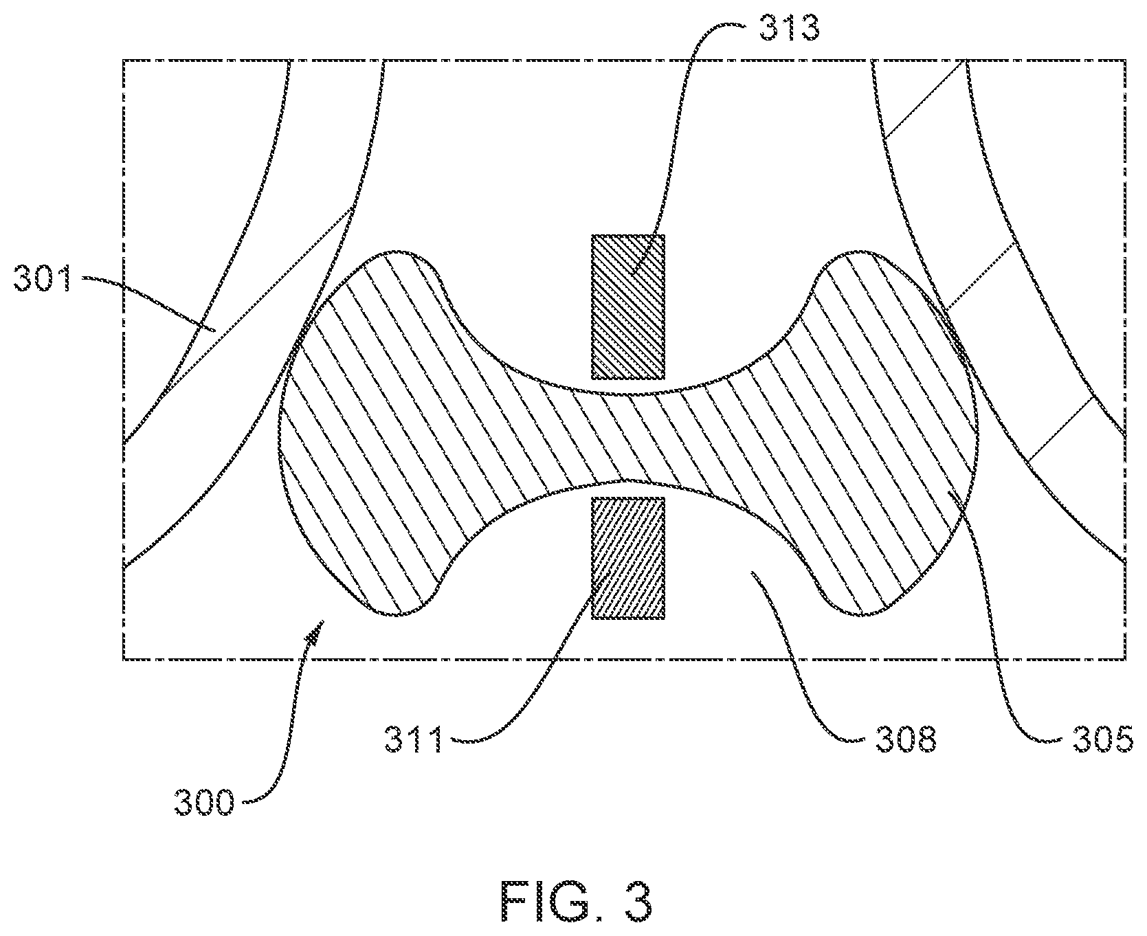
FIG. 3 is a cross-sectional side view of an ablation device disposed in a pulmonary vein, according to embodiments.
FIG. 4A is a cross-sectional side view of an ablation device disposed in a pulmonary vein, according to embodiments. FIG. 4B is a perspective view of an ablation zone associated with the ablation device depicted in FIG. 4A when disposed in a pulmonary vein, according to embodiments.
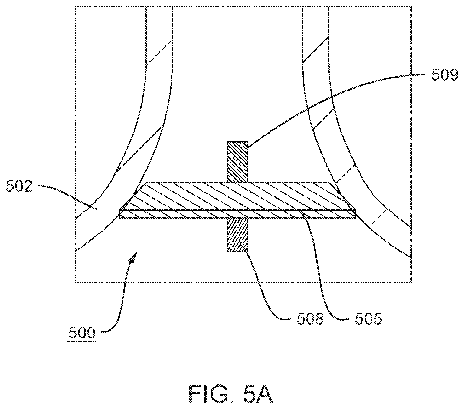
FIG. 5A is a cross-sectional side view of an ablation device disposed in a pulmonary vein, according to embodiments. FIG. 5B is a cross-sectional side view of the ablation device depicted in FIG. 5A disposed in a pulmonary vein.
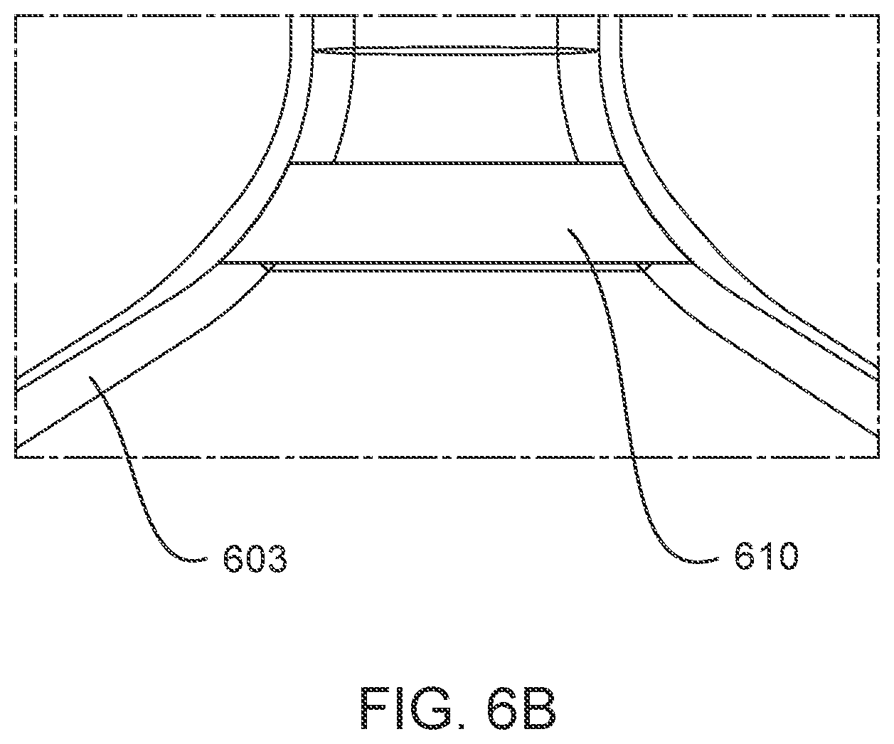
FIG. 6A is a cross-sectional side view of an ablation device disposed in a pulmonary vein, according to embodiments. FIG. 6B is a cross-sectional side view of an ablation zone of the ablation device depicted in FIG. 6A disposed in a pulmonary vein.
FIG. 7 is a side view of an ablation device, according to embodiments.
FIG. 8 is a side view of an ablation device, according to embodiments.
FIG. 9 is a perspective view of an ablation device, according to embodiments.
FIG. 10 is a schematic side view of a portion of a wall of an inflatable member of an ablation device, according to embodiments.
FIG. 11 is a schematic side view of a portion of a wall of an inflatable member of an ablation device, according to embodiments.
FIGS. 12A and 12B are different views of an ablation device, according to embodiments.
FIG. 13 is a cross-sectional side view of the ablation device depicted in FIGS. 12A and 12B.
FIG. 14 is a cross-sectional side view of an ablation zone of the ablation device depicted in FIGS. 12A and 12B.
FIG. 15 is an example waveform showing a sequence of voltage pulses with a pulse width defined for each pulse, according to embodiments.
FIG. 16 schematically illustrates a hierarchy of pulses showing pulse widths, intervals between pulses, and groupings of pulses, according to embodiments.
FIG. 17 provides a schematic illustration of a nested hierarchy of monophasic pulses displaying different levels of nested hierarchy, according to embodiments.
FIG. 18 is a schematic illustration of a nested hierarchy of biphasic pulses displaying different levels of nested hierarchy, according to embodiments.
FIG. 19 illustrates schematically a time sequence of electrocardiograms and cardiac pacing signals together with atrial and ventricular refractory time periods and indicating a time window for irreversible electroporation ablation, according to embodiments.
FIGS. 20A-20B illustrates a method for tissue ablation, according to embodiments.
DETAILED DESCRIPTION
Described here are systems, devices, and methods for ablating tissue through irreversible electroporation. Generally, an apparatus for delivering a pulse waveform to tissue may include a first catheter (e.g., shaft) defining a longitudinal axis. An expandable/inflatable member may be coupled to a distal portion of the first catheter. A first electrode may be coupled to the distal portion of the first catheter and proximal to the inflatable member. A second catheter (e.g., shaft) or tubular lumen may be disposed within a lumen of the first catheter and a chamber of the expandable/inflatable member where the second catheter may be slidable relative to the first catheter. The expandable/inflatable member may be coupled to a distal end of the second catheter. A second electrode may be coupled to the distal portion of the second catheter and distal to the inflatable member. In some embodiments the second catheter, and in particular its distal portion, may be steerable linearly relative to the first catheter. Thus in some embodiments, the second electrode may be steerable relative to the first electrode. A proximal portion of the expandable/inflatable member may be coupled to the distal portion of the first catheter and a distal portion of the expandable/inflatable member may be coupled to the distal portion of the second catheter or tubular lumen. The second catheter may have a lumen diameter sufficient to pass a guidewire through the lumen. The guidewire may provide mechanical support for the first and second catheters. In some embodiments, the first electrode may comprise a first set of electrodes and the second electrode may comprise a second set of electrodes.
Generally, a system for delivering a pulse waveform to tissue may include a signal generator configured for generating a pulse waveform and an ablation device coupled to the signal generator and configured to receive the pulse waveform. The ablation device may include an expandable/inflatable member (e.g., a balloon) coupled to a distal portion of a first catheter for delivering energy to ablate tissue by irreversible electroporation. One or more electrodes may be formed proximal to the expandable/inflatable member on a surface of the first catheter.
In some embodiments, a system may include a signal generator configured for generating a pulse waveform. An ablation device may be coupled to the signal generator and configured for receiving the pulse waveform. The ablation device may include a handle configured to move the second electrode relative to the first electrode. The system may include a cardiac stimulator for generation of pacing signals and for delivery of pulse waveforms in synchrony with the pacing signal. In some embodiments, one or more of the electrodes may have an insulated electrical lead associated therewith, the insulated electrical lead configured for sustaining a voltage potential of at least about 700 V without dielectric breakdown of its corresponding insulation, the insulated electrical lead disposed in a lumen of the catheter. In some embodiments, one or more of the electrodes may be independently addressable.
In some embodiments, a pulse waveform may include a first level of a hierarchy of the pulse waveform in the form of a first set of pulses, each pulse having a pulse time duration, a first time interval separating successive pulses. A second level of the hierarchy of the pulse waveform includes a plurality of first sets of pulses as a second set of pulses, a second time interval separating successive first sets of pulses, the second time interval being at least three times the duration of the first time interval. A third level of the hierarchy of the pulse waveform includes a plurality of second sets of pulses as a third set of pulses, a third time interval separating successive second sets of pulses, the third time interval being at least thirty times the duration of the second level time interval. In some of these embodiments, the pulse waveform includes a fourth level of the hierarchy of the pulse waveform includes a plurality of third sets of pulses as a fourth set of pulses, a fourth time interval separating successive third sets of pulses, the fourth time interval being at least ten times the duration of the third level time interval.
In some embodiments, a distal portion of the ablation device may further include a radiopaque portion. In some embodiments, the second catheter defines a lumen therethrough.
In some embodiments, a method of ablation via irreversible electroporation includes the steps of advancing an ablation device towards a pulmonary vein ostium. The ablation device may include a first catheter, a second catheter or tubular lumen, and an expandable/inflatable member coupled to a distal end of the catheter shaft. The inflatable member may be flanked by electrodes mounted on the device proximal and distal to the inflatable member. A pulse waveform may be generated. The pulse waveform may be delivered to the pulmonary vein ostium via the electrodes on the ablation device.
In some embodiments, the expandable/inflatable member of the ablation device may be transitioned from a first configuration to a second configuration. In some embodiments, transitioning the expandable/inflatable member from the first configuration to the second configuration includes infusing the expandable/inflatable member with distilled or deionized water which may induce mechanically expansion. In some embodiments, pulsed electric field ablation energy may be delivered through the first set of electrodes and the second set of electrodes of the ablation device. In some embodiments, the ablation device is configured to generate an electric field intensity of between about 200 V/cm and about 800 V/cm.
In some embodiments, the ablation device may include a handle. In some embodiments, a portion of the first catheter shaft proximal to the proximal or first set of electrodes can be deflectable, with the deflection controlled by a knob or other control mechanism on the handle. The method may further include the steps of deflecting a portion of the ablation device using the handle. For example, a second electrode may be moved relative to the first electrode and the shape of the expandable/inflatable member in the second configuration may be modified by infusion of distilled or deionized water through an infusion port attached to the handle, and the distal shaft may be deflected using a deflection knob on the handle.
In some embodiments, the method may include the steps of creating a transseptal opening into a left atrium, advancing a guidewire and a steerable sheath into the left atrium through the transseptal opening, and advancing the ablation device into a pulmonary vein over the guidewire. In some embodiments, the method may include the steps of creating a first access site in a patient, advancing the guidewire through the first access site and into a right atrium, advancing the dilator and a steerable sheath over the guidewire and into the right atrium, advancing the dilator from the right atrium into the left atrium through an interatrial septum to create the transseptal opening, and dilating the transseptal opening using the dilator. In some embodiments, a second access site may be created in the patient for advancing a cardiac pacing catheter. In some embodiments, the method may include the steps of advancing the pacing catheter into a right ventricle, generating a pacing signal for cardiac stimulation of the heart using the cardiac stimulator, and applying the pacing signal to the heart using the cardiac stimulator, and then delivering a pulsed electric field voltage pulse waveform in synchronization with the pacing signal once the ablation device with the inflatable member is suitably positioned at a pulmonary vein ostium.
In some embodiments, the method may include the step of fluoroscopically imaging a radiopaque portion of the ablation device during one or more steps. In some embodiments, the first access site is a femoral vein. In some embodiments, the interatrial septum includes a fossa ovalis.
In some embodiments, the pulse waveform may include a first level of a hierarchy of the pulse waveform in the form of a first set of pulses, each pulse having a pulse time duration, a first time interval separating successive pulses. A second level of the hierarchy of the pulse waveform includes a plurality of first sets of pulses as a second set of pulses, a second time interval separating successive first sets of pulses, the second time interval being at least three times the duration of the first time interval. A third level of the hierarchy of the pulse waveform includes a plurality of second sets of pulses as a third set of pulses, a third time interval separating successive second sets of pulses, the third time interval being at least thirty times the duration of the second level time interval. In some of these embodiments, the pulse waveform includes a fourth level of the hierarchy of the pulse waveform includes a plurality of third sets of pulses as a fourth set of pulses, a fourth time interval separating successive third sets of pulses, the fourth time interval being at least ten times the duration of the third level time interval.
The systems, devices, and methods described herein may be used to generate large electric field magnitudes at desired regions of interest to generate irreversible electroporation. An irreversible electroporation system as described herein may include a signal generator and a processor configured to apply one or more voltage pulse waveforms to a set of electrodes to deliver energy to a region of interest. The pulse waveforms disclosed herein may aid in therapeutic treatment of cardiac arrhythmias such as atrial fibrillation. In order to deliver the pulse waveforms generated by the signal generator, one or more electrodes of the ablation device may have an insulated electrical lead configured for sustaining a voltage potential of at least about 700 V without dielectric breakdown of its corresponding insulation. In some embodiments, at least some of the electrodes may be independently addressable such that each electrode may be controlled (e.g., deliver energy) independently of any other electrode of the device.
The term "electroporation" as used herein refers to the application of an electric field to a cell membrane to change the permeability of the cell membrane to the extracellular environment. The term "reversible electroporation" as used herein refers to the application of an electric field to a cell membrane to temporarily change the permeability of the cell membrane to the extracellular environment. For example, a cell undergoing reversible electroporation can observe the temporary and/or intermittent formation of one or more pores in its cell membrane that close up upon removal of the electric field. The term "irreversible electroporation" as used herein refers to the application of an electric field to a cell membrane to permanently change the permeability of the cell membrane to the extracellular environment. For example, a cell undergoing irreversible electroporation can observe the formation of one or more pores in its cell membrane that persist upon removal of the electric field.
Pulse waveforms for electroporation energy delivery as disclosed herein may enhance the safety, efficiency and effectiveness of energy delivery to tissue by reducing the electric field threshold associated with irreversible electroporation, thus yielding more effective ablative lesions with a reduction in total energy delivered. In some embodiments, the voltage pulse waveforms disclosed herein may be hierarchical and have a nested structure. For example, the pulse waveform may include hierarchical groupings of pulses having associated timescales. In some embodiments, the methods, systems, and devices disclosed herein may comprise one or more of the methods, systems, and devices described in one or more of International Application Serial No. PCT/US2016/057664, filed on Oct. 19, 2016, and titled "SYSTEMS, APPARATUSES AND METHODS FOR DELIVERY OF ABLATIVE ENERGY TO TISSUE," and U.S. patent application Ser. No. 16/405,515, filed on May 7, 2019, and titled "SYSTEMS, APPARATUSES AND METHODS FOR DELIVERY OF ABLATIVE ENERGY TO TISSUE," the contents of each of which are hereby incorporated by reference in its entirety.
In some embodiments, the systems may further include a cardiac stimulator used to synchronize the generation of the pulse waveform to a paced heartbeat. The cardiac stimulator may electrically pace the heart with a cardiac stimulator and ensure pacing capture to establish periodicity and predictability of the cardiac cycle. A time window within a refractory period of the periodic cardiac cycle may be selected for voltage pulse waveform delivery. Thus, voltage pulse waveforms may be delivered in the refractory period of the cardiac cycle so as to avoid disruption of the sinus rhythm of the heart. In some embodiments, an ablation device may include one or more catheters, guidewires, expandable/inflatable members, and electrodes. The ablation device may transform into different configurations (e.g., deflated and inflated) to position the device within an endocardial space.
Generally, to ablate tissue, one or more catheters may be advanced in a minimally invasive fashion through vasculature to a target location. The methods described here may include introducing a device into an endocardial space of the heart and disposing the device at the ostium of a pulmonary vein. A pulse waveform may be generated and delivered to electrodes of the device to ablate tissue. In some embodiments, the pulse waveform may be generated in synchronization with a pacing signal of the heart to avoid disruption of the sinus rhythm of the heart. In some embodiments, the electrodes may be configured in anode-cathode subsets. The pulse waveform may include hierarchical waveforms to aid in tissue ablation and reduce damage to healthy tissue.
I. Systems
Overview
Disclosed herein are systems and devices configured for tissue ablation via the selective and rapid application of voltage pulse waveforms to aid tissue ablation, resulting in irreversible electroporation. Generally, a system for ablating tissue described here may include a signal generator and an ablation device having one or more electrodes and an expandable/inflatable member (e.g., balloon) for the selective and rapid application of DC voltage to drive electroporation. As described herein, the systems and devices may be deployed endocardially to treat cardiac arrhythmias. Voltage pulse waveforms may be applied to a subset of the electrodes, with suitable anode/cathode electrode selections. A pacing signal for cardiac stimulation may be generated and used to generate the pulse waveform by the signal generator in synchronization with the pacing signal.
Generally, the systems and devices described herein include one or more catheters configured to ablate tissue in a ventricle of a heart. FIG. 1 illustrates an ablation system (100) configured to deliver voltage pulse waveforms. The system (100) may include an apparatus (120) including a signal generator (122), processor (124), memory (126), and cardiac stimulator (128). The apparatus (120) may be coupled to an ablation device (110), and optionally to a pacing device (130).
The signal generator (122) may be configured to generate pulse waveforms for irreversible electroporation of tissue, such as, for example, a pulmonary vein. For example, the signal generator (122) may be a voltage pulse waveform generator and be configured to deliver a pulse waveform to the ablation device (110). The return electrode (140) in some embodiments may be coupled to a patient (e.g., disposed on a patient's back) to allow current to pass from the ablation device (110) through the patient and then to the return electrode (140). In other embodiments, an electrode of the ablation device may serve as a return, such that a separate return electrode (140) may be absent. The processor (124) may incorporate data received from memory (126) to determine the parameters of the pulse waveform to be generated by the signal generator (122), while some parameters such as voltage can be input by a user. The memory (126) may further store instructions to cause the signal generator (122) to execute modules, processes and/or functions associated with the system (100), such as pulse waveform generation and/or cardiac pacing synchronization. For example, the memory (126) may be configured to store pulse waveform and/or heart pacing data for pulse waveform generation and/or cardiac pacing, respectively.
In some embodiments, the ablation device (110) may include a catheter having an expandable/inflatable member (e.g., balloon) configured to deliver the pulse waveforms described in more detail below. In each of the embodiments described herein, the expandable/inflatable member may be inflated using, for example, saline or, in some cases, an electrically non-conducting or very poorly conducting fluid (e.g., gas, liquid such as distilled water, deionized water, etc.). Fluid may be input through a lumen of a catheter coupled to the expandable/inflatable member. For example, the ablation device (110) may be introduced into an endocardial space and positioned at the ostium of a pulmonary vein and inflated so that the inflatable member is well apposed or engaged at the walls of the pulmonary vein, and then the pulse waveforms may be delivered to ablate tissue. The ablation device (110) may include one or more electrodes (112), which may, in some embodiments, be independently addressable electrodes. Each electrode may include an insulated electrical lead configured to sustain a voltage potential of at least about 700 V without dielectric breakdown of its corresponding insulation. In some embodiments, the insulation on each of the electrical leads may sustain an electrical potential difference of between about 200 V to about 3,000 V across its thickness without dielectric breakdown. For example, the electrodes (112) may be grouped into one or more anode-cathode subsets such as, for example, a subset including one proximal electrode and one distal electrode. In some embodiments, the distal electrode may include at least a portion of an expandable/inflatable member. As used herein, proximal is towards a handle of an ablation device and distal is towards a tip end of the ablation device.
When used, the pacing device (130) may be suitably coupled to the patient (not shown) and configured to receive a heart pacing signal generated by the cardiac stimulator (128). An indication of the pacing signal may be transmitted by the cardiac stimulator (128) to the signal generator (122). Based on detection of the pacing signal by the generator, a voltage pulse waveform may be generated by the signal generator (122) for ablation delivery. In some embodiments, the signal generator (122) may be configured to generate the pulse waveform in synchronization with the indication of the pacing signal (e.g., such that the ablation delivery occurs during a refractory window of a cardiac chamber). In some embodiments, the refractory window may be a common refractory window of two cardiac chambers such as an atrium and a ventricle. For example, in some embodiments, the common refractory window may start substantially immediately following a ventricular pacing signal (or after a very small delay) and last for a duration of approximately 250 ms or less thereafter. In such embodiments, an entire pulse waveform may be delivered within this duration.
The processor (124) may be any suitable processing device configured to run and/or execute a set of instructions or code. The processor may be, for example, a general purpose processor, a Field Programmable Gate Array (FPGA), an Application Specific Integrated Circuit (ASIC), a Digital Signal Processor (DSP), and/or the like. The processor may be configured to run and/or execute application processes and/or other modules, processes and/or functions associated with the system and/or a network associated therewith (not shown). The underlying device technologies may be provided in a variety of component types, e.g., metal-oxide semiconductor field-effect transistor (MOSFET) technologies like complementary metal-oxide semiconductor (CMOS), bipolar technologies like emitter-coupled logic (ECL), polymer technologies (e.g., silicon-conjugated polymer and metal-conjugated polymer-metal structures), mixed analog and digital, and/or the like.
The memory (126) may include a database (not shown) and may be, for example, a random access memory (RAM), a memory buffer, a hard drive, an erasable programmable read-only memory (EPROM), an electrically erasable read-only memory (EEPROM), a read-only memory (ROM), Flash memory, etc. The memory (126) may store instructions to cause the processor (124) to execute modules, processes and/or functions associated with the system (100), such as pulse waveform generation and/or cardiac pacing.
The system (100) may be in communication with other devices (not shown) via, for example, one or more networks, each of which may be any type of network. A wireless network may refer to any type of digital network that is not connected by cables of any kind. However, a wireless network may connect to a wireline network in order to interface with the Internet, other carrier voice and data networks, business networks, and personal networks. A wireline network is typically carried over copper twisted pair, coaxial cable or fiber optic cables. There are many different types of wireline networks including, wide area networks (WAN), metropolitan area networks (MAN), local area networks (LAN), campus area networks (CAN), global area networks (GAN), like the Internet, and virtual private networks (VPN). Hereinafter, network refers to any combination of combined wireless, wireline, public and private data networks that are typically interconnected through the Internet, to provide a unified networking and information access solution.
Ablation Device
The systems described here may include one or more multi-electrode ablation devices configured to ablate tissue in a pulmonary vein of a heart for treating indications such as arrhythmia. FIG. 2A is a side view of an ablation device (200) (e.g., structurally and/or functionally similar to the ablation device (110)) including a first catheter (203) (e.g., catheter shaft or outer shaft) defining a lumen, a second catheter (210) (e.g., a tubular guidewire or inner shaft defining a lumen), and an inflatable member (207). The second catheter (210) may be disposed within a lumen of the first catheter (203) and a chamber of the inflatable member (207) where the second catheter (210) may be slidable relative to the first catheter (203). The inflatable member (e.g., balloon) (207) may be coupled to the second catheter (210) such that the second catheter may pass through an inner chamber of the inflatable member (207). A first electrode (213) may be disposed on a surface of a distal portion (217) of the first catheter (203) and may be either separated from or attached to a proximal portion of the inflatable member (207). A second electrode (220) may be disposed on a distal portion (223) of the second catheter (210) and may be either separated from or attached to a distal portion of the inflatable member (207). The distal portion (223) of the second catheter (217) may be linearly moveable and about a portion distal to the first catheter (203). In some embodiments, the second electrode (223) may be moveable relative to the first electrode (213). A proximal portion of the inflatable member (207) may be coupled to the distal portion of the first catheter (203).
A proximal end of the inflatable member (207) may be attached proximal to a distal end of the first catheter (203). The first electrode (213) may be disposed on the first catheter (203) just proximal to the proximal end of the inflatable member (207). In FIGS. 2A-2B, the second catheter or tubular lumen (210) is shown as extending from the distal end (217) of the first catheter (203) and out of a distal end of the inflatable member (207). The second electrode (220) is disposed on a surface of the second catheter (210) proximal to the distal end (223) of the second catheter (210). The distal end of the inflatable member (207) may be attached to the second catheter (210) just proximal to the second electrode (220).
In some embodiments, a handle (not shown) may be coupled to a proximal portion of the ablation device (200) and may include a bending mechanism (not shown) (e.g., knob, switch, pull wires) configured to deflect a portion of the second catheter (210) just proximal to the first catheter (203). For example, operation of a pull wire of the handle may increase or decrease a curvature in a distal portion of the first catheter. A fluid port can attach to the handle for infusion of fluid such as distilled water or deionized water to inflate the inflatable member. In embodiments, the handle can incorporate a deployment mechanism configured to advance and retract the second catheter or guidewire lumen (210) such that a distance between the first electrode (213) and the second electrode (220) may be varied. For example, after the inflatable member is positioned suitably in a pulmonary vein, it can be inflated and well-apposed in the vein. Subsequently, the first electrode (213) and the second electrode (220) may be brought closer together by retracting the second catheter (210) relative to the first catheter (203). In this manner, the device may be configured for PEF ablation delivery.
The inflatable member (207) may be configured to transition between a first configuration (e.g., deflated inflatable member in FIG. 2B) and a second configuration (e.g., inflated inflatable member in FIG. 2A). The inflatable member (207) in the first configuration may be in a compact, deflated state suitable for advancement through vasculature. For example, the inflatable member (207) in the first configuration may be substantially empty of fluid, such as sterile distilled or deionized water or saline. In some embodiments, fluid may enter the inflatable member (207) via an infusion port of a handle coupled to the ablation device. The inflatable member (207) in the second configuration may hold a volume of saline or distilled or deionized water that fills and inflates the inflatable member (207) to an appropriate size and shape (e.g., having a diameter to contact a diameter of a pulmonary vein) under pressure from a syringe or other infusion device. The inflatable member (207) may transition to an intermediate configuration between the first and second configuration as necessary, for example, to conform to a lumen or advance the device through vasculature. In some embodiments, the inflatable member may be pressurized using one or more of a hand-operated syringe, pump, infusion device, combinations thereof, and the like. In some embodiments, an infusion pressure may be between about 2 psi and about 20 psi.
Although FIGS. 2A and 2B depict an ablation device having one proximal electrode (213) and one distal electrode (223), it should be appreciated that more electrodes can be used in other embodiments. For example, the first electrode (213) may include a set of electrodes (e.g., two or more proximal electrodes formed along a length of the first catheter). Likewise, the second electrode (220) may include a set of electrodes (e.g., two or more distal electrodes formed along a length of the second catheter). In some embodiments, a diameter of the electrodes (213, 220) may be between about 1 mm and about 6 mm, including all values and sub-ranges in between. A length of the electrodes (213, 220) (measured along a longitudinal axis of the first and second catheters) may be between about 1 mm and about 8 mm, including all values and sub-ranges in between. In some embodiments, a set of electrodes disposed on a surface of the first catheter (e.g., a set of two or more proximal electrodes (213)) may be spaced apart by between about 0.5 mm and about 9 mm, including all values and sub-ranges in between. In some embodiments, a set of electrodes disposed on a surface of the second catheter (e.g., a set of two or more distal electrodes (220)) may be spaced apart by between about 0.5 mm and about 9 mm, including all values and sub-ranges in between. In some embodiments, the inflatable member in a second configuration (e.g., inflated, deployed) may have an outer diameter (e.g., maximum width) of between about 20 mm and about 40 mm, including all values and sub-ranges in between. In some embodiments, the inflatable member in a first configuration (e.g., deflated, undeployed state) may have a length (measured along a longitudinal axis of the second catheter) of between about 10 mm and about 80 mm, including all values and sub-ranges in between, when the first and second electrodes (213, 220) are maximally separated.
FIG. 3 illustrates an ablation device (300) including an inflatable member (305) (e.g., structurally and/or functionally similar to the ablation device (110, 200)) in a second configuration (e.g., inflated) and deployed coaxially at an ostium of a pulmonary vein (301). The ablation device (300) includes a first electrode (311) coupled to a proximal end of the inflatable member (305) and a second electrode (313) coupled to a distal end of the inflatable member (305). A first catheter and a second catheter (e.g., a guidewire catheter defining a lumen), similar to those described herein, are not shown in FIG. 3 for the sake of clarity. In FIG. 3, the second catheter or guidewire lumen (not shown) has been retracted relative to the first catheter such that the first electrode (311) and second electrode (313) are minimally separated. When the inflatable member is in the second configuration and the first and second electrodes (311, 313) are retracted towards each other, a central region (308) of the inflatable member (305) may likewise be retracted towards each other or pulled in such that the proximal and distal ends of the inflatable member (305) are brought closer together. In this manner, the first and second electrodes (311, 313) may be at least partially surrounded by portions of the inflatable member (305) (where the balloon is folded inward).
FIG. 4A is a cross-sectional side view of an ablation device (400) (e.g., structurally and/or functionally similar to the ablation device (110, 200, 300)) disposed at a pulmonary vein ostium (402). In particular, a longitudinal axis of the ablation device (400) is disposed at an angle relative to a longitudinal axis of the pulmonary vein. FIG. 4B is a cross-sectional perspective view of an ablation zone (408) of the ablation device depicted in FIG. 4A disposed in a pulmonary vein (411). The ablation device (400) may include an inflatable member (404) and a first electrode (e.g., electrode proximal to the inflatable member (404)) and a second electrode (e.g., electrode distal to the inflatable member (404)). The first and second electrodes may be configured as an anode-cathode pair to deliver ablation energy to tissue. The ablation zone (408) may form a continuous ring-like shape on the pulmonary vein ostium (402) when the anode-cathode pair delivers energy that exceeds a threshold value required to generate irreversible electroporation.
FIG. 5A is a cross-sectional side view of an ablation device (500) (e.g., structurally and/or functionally similar to the ablation device (110, 200, 300, 400)) disposed in a pulmonary vein ostium (502) (e.g., deployed coaxially). The ablation device (500) includes a first electrode (508) coupled to a proximal end of the inflatable member (505) and a second electrode (509) coupled to a distal end of the inflatable member (505). Alternatively or in addition, the first and second electrodes may be respectively coupled to the distal portion of the first catheter proximal to the inflatable member and to the distal portion of the second catheter/guidewire lumen distal to the inflatable member. A first catheter or outer shaft and a second catheter or inner shaft (e.g., a guidewire lumen), similar to those described herein, are not shown in FIGS. 5A-5B for the sake of clarity. In FIG. 5A, the inflatable member (505) when inflated may form a frustum shape (e.g., a trapezoidal shape when viewed in lateral section). In some embodiments, a diameter of the inflatable member (505) at its widest portion may be between about 20 mm and about 40 mm, including all values and sub-ranges in between. A length of the inflatable member (505) (measured along a longitudinal axis of the first and second catheter) when fully deployed may be between about 3 mm and about 30 mm, including all values and sub-ranges in between. FIG. 5B is a cross-sectional side view of the ablation device (500) depicted in FIG. 5A where a longitudinal axis of the ablation device (500) is disposed at an angle relative to a longitudinal axis of the pulmonary vein (502).
FIG. 6A is a cross-sectional side view of an ablation device (600) (e.g., structurally and/or functionally similar to the ablation device (110, 200, 300, 400, 500)) disposed in a pulmonary vein ostium (603) (e.g., deployed coaxially). The ablation device (600) includes a first electrode (609) coupled to a proximal end of the inflatable member (606) and a second electrode (611) coupled to a distal end of the inflatable member (606). Additionally or alternatively, the first and second electrodes may be respectively coupled to the distal portion of the first catheter/outer shaft proximal to the inflatable member and to the distal portion of the second catheter/guidewire lumen distal to the inflatable member. A first catheter/outer shaft and a second catheter (e.g., an inner shaft defining a lumen), similar to those described herein, are not shown in FIGS. 6A-6B for the sake of clarity. The inflatable member (606) in the inflated configuration may form a rhombus-like shape in a lateral view, as shown in FIG. 6A. FIG. 6B is a lateral section view of an ablation zone (610) of the ablation device (600) depicted in FIG. 6A disposed in a pulmonary vein (603). The first and second electrodes (609, 611) may be configured as an anode-cathode pair to deliver ablation energy to tissue. The ablation zone (610) may form a ring-like shape on the pulmonary vein ostium (603) when the anode-cathode pair delivers energy that exceeds a threshold value required to generate irreversible electroporation.
FIG. 7 is a schematic cross-sectional side view of an ablation device (700) (e.g., structurally and/or functionally similar to the ablation device (110, 200, 300, 400, 500, 600)). The ablation device (700) may include a first catheter (703) (e.g., outer catheter shaft) defining a lumen, a second catheter (705) (e.g., an inner shaft defining a lumen), and an inflatable member (710). The second catheter (705) may be disposed within a lumen of the first catheter (703) and a chamber of the inflatable member (710) where the second catheter (705) may be slideable relative to the first catheter (703). The inflatable member (e.g., balloon) (710) may be coupled to the second catheter (705) such that the second catheter (705) may pass through an inner chamber of the inflatable member (710). A first electrode (707) may be disposed on a surface of a distal portion of the first catheter (703) and just proximal to the inflatable member (710). A second electrode (709) may be disposed on a distal portion (712) of the second catheter (705) and just distal to the inflatable member (710). The second catheter (705) may be linearly slideable relative to the first catheter (703). Thus, the second electrode (709) may be linearly slideable relative to the first electrode (707). A proximal portion of the inflatable member (710) may be coupled to the distal portion of the first catheter (703). In FIG. 7, the inflatable member (710) may form an approximately rhombus-like shape.
In some embodiments, the ablation device (700) may include a handle (not shown) coupled to a proximal portion of the ablation device (700) and may include a mechanism (not shown) (e.g., knob, switch, pull wires) configured to advance and retract the second catheter or guidewire (705) relative to the first catheter (703) such that a distance between the first electrode (707) and the second electrode (709) may be varied. For example, the first electrode (707) and the second electrode (709) may be brought closer together by retracting the second catheter (705) relative to the first catheter (703). In FIG. 7, a central portion (713) of a distal end of the inflatable member (710) is shown as retracted toward a proximal end of the inflatable member (710).
When suitably inflated, a proximal major portion (715) and a distal major portion (719) of the inflatable member (710) may be angled relative to a longitudinal axis of the first catheter (703) such that a surface of the inflatable member (710) forms an angle (731) with respect to the longitudinal axis that is greater than about 45 degrees. In some embodiments, a middle portion (721) of the inflatable member (710) may be relatively short compared to the major portions (715, 719).
Although FIG. 7 depicts an ablation device having one proximal electrode (707) and one distal electrode (709), it should be appreciated that more electrodes can be used in other embodiments. For example, the first electrode (707) may include a set of electrodes (e.g., two or more proximal electrodes). Likewise, the second electrode (709) may include a set of electrodes (e.g., two or more distal electrodes). In some embodiments, a diameter of the electrodes (707, 709) may be between about 1 mm and about 6 mm, including all values and sub-ranges in between. A length of the electrodes (707, 709) (measured along a longitudinal axis of the first and second catheters) may be between about 1 mm and about 8 mm, including all values and sub-ranges in between. In some embodiments, a set of electrodes disposed on a surface of the first catheter (703) (e.g., a set of two or more proximal electrodes (707)) may be spaced apart by between about 0.5 mm and about 9 mm, including all values and sub-ranges in between. In some embodiments, a set of electrodes disposed on a surface of the second catheter (705) (e.g., a set of two or more distal electrodes (709)) may be spaced apart by between about 0.5 mm and about 9 mm, including all values and sub-ranges in between. In some embodiments, the inflatable member (710) in a second configuration (e.g., inflated) may have an outer diameter of between about 20 mm and about 40 mm, including all values and sub-ranges in between. In some embodiments, the inflatable member (710) in a first configuration (e.g., deflated, undeployed state) may have a length (measured along a longitudinal axis of the second catheter) of between about 10 mm and about 80 mm, including all values and sub-ranges in between, when the first and second electrodes (707, 709) are maximally separated. In a fully deployed state with the second catheter (705) retracted for minimal separation between the first and second electrodes (707, 709), a length of the inflatable member (710) (measured along a longitudinal axis of the first catheter (703) may be between about 3 mm and about 30 mm, including all values and sub-ranges in between.
FIG. 8 is a schematic cross-sectional side view of an ablation device (800) (e.g., structurally and/or functionally similar to the ablation device (110, 200, 300, 400, 500, 600, 700)). The ablation device (800) may include a first catheter (803) (e.g., outer catheter shaft) defining a lumen, a second catheter (805) (e.g., an inner shaft defining a guidewire lumen), and an inflatable member (810). The second catheter (805) may be disposed within a lumen of the first catheter (803) and a chamber of the inflatable member (810) where the second catheter (805) may be slidable relative to the first catheter (803). The inflatable member (e.g., balloon) (810) may be coupled to the second catheter (805) such that the second catheter (805) may pass through an inner chamber of the inflatable member (810). A first electrode (807) may be disposed on a surface of a distal portion of the first catheter (803) and just proximal to the inflatable member (810). A second electrode (809) may be disposed on a distal portion (812) of the second catheter (805) and just distal to the inflatable member (810). The second catheter (805) may be linearly slideable relative to the first catheter (803). Thus, the second electrode (809) may be slideable relative to the first electrode (807). A proximal portion of the inflatable member (810) may be coupled to the first catheter (803) and a distal portion of the inflatable member (810) may be coupled to the second catheter (805) such that the second catheter (805) may pass through an inner chamber of the inflatable member (810).
In some embodiments, the ablation device (800) may include a handle (not shown) coupled to a proximal portion of the ablation device (800) and may include a mechanism (not shown) (e.g., knob, switch, pull wires) configured to advance and retract the second catheter (805) such that a distance between the first electrode (807) and the second electrode (809) may be varied. For example, the first electrode (807) and the second electrode (809) may be brought closer together by retracting the second catheter or guidewire (805) relative to the first catheter (803). In FIG. 8, a central portion (813) of a distal end of the inflatable member (810) is shown as retracted toward a proximal end of the inflatable member (810) using a handle and a bending mechanism as described herein.
When suitably inflated, a proximal major portion (815) and a distal major portion (819) of the inflatable member (810) may be gently curved with the surface locally having an angle relative to a longitudinal axis of the first catheter (803) such that a surface of the inflatable member (810) locally forms an angle (831) with respect to the longitudinal axis. In some embodiments, a middle portion (821) of the inflatable member (810) may be relatively short in length compared to the major portions (815, 819). In some embodiments, the major portions (815, 819) may be gently curved with steep slopes with respect to the longitudinal axis (825) of the first catheter (803). In FIG. 8, a local tangent (829) to a surface of the inflatable member (i.e., the component of the local tangent in the plane defined by radial and axial directions) may form an angle (831) with the longitudinal axis (825) that is greater than about 45 degrees.
In some embodiments, a middle portion (821) of the inflatable member (810) may be relatively short in length compared to the major portions (815, 819). When the inflatable member (810) is inflated (e.g., suitably pressurized), the middle portion (821) may bulge as shown in FIG. 8. In some embodiments, the middle portion (821) of the inflatable member (810) may be constructed of thinner material compared to the major portions (815, 819). For example, the thickness of a wall of an inflatable member (810) of the major portions (815, 819) may be at least 20% larger than the thickness of the wall at the middle portion (821). In some embodiments, the thickness of a wall of an inflatable member (810) of the major portions (815, 819) may be at least 50% larger than the thickness of the wall at the middle portion (821). In some embodiments, the thickness of a wall of an inflatable member (810) of the major portions (815, 819) may be at least 100% larger than the thickness of the wall at the middle portion (821).
FIG. 10 is a schematic side view of portion of the wall (1000) of an uninflated inflatable member including a proximal portion (1003), a middle portion (1005), and a distal portion (1007). FIG. 10 illustrates schematically that the thickness (1011) of the proximal portion and thickness (1013) of the distal portion may be significantly larger than the thickness (1012) of the middle portion.
FIG. 11 is a schematic side view of a portion of a wall (1700) of an inflatable member of an ablation device, including a proximal portion (1703), a middle portion (1705), and a distal portion (1707), as arranged along a longitudinal or central axis (1710) of the inflatable member. Any of the inflatable members described herein (e.g., inflatable members 207, 305, 404, 505, 606, etc.) can have a wall that is structurally and/or functionally similar to the wall (1700) depicted in FIG. 11. The proximal portion (1703) of the wall (1700) can have a length L1 extending along the longitudinal axis (1710), the middle portion (1705) of the wall (1700) can have a length L2 extending along the longitudinal axis (1710), and the distal portion (1707) of the wall (1700) can have a length L3 extending along the longitudinal axis (1710). The lengths L1 and L3 can be greater than L2, with the ratios L1/L2 and L3/L2 being greater than three.
As depicted in FIG. 11, the proximal portion (1703) of the wall (1700) of the inflatable member can have a maximum thickness D1, the middle portion (1705) of the wall (1700) can have a minimum thickness D2, and the distal portion (1707) of the wall (1700) can have a maximum thickness D3. In some embodiments, thicknesses D1 and D3 of the proximal and distal portions (1703, 1707), respectively, can be equal to one another (or about equal to one another), and the thickness D2 of the middle portion (1705) can be equal to or less than about a third of the thicknesses D1 and D3.
Although FIG. 8 depicts an ablation device having one proximal electrode (807) and one distal electrode (809), it should be appreciated that more electrodes can be used in other embodiments. For example, the first electrode (807) may include a set of electrodes (e.g., two or more proximal electrodes). Likewise, the second electrode (809) may include a set of electrodes (e.g., two or more distal electrodes). In some embodiments, a diameter of the electrodes (807, 809) may be between about 1 mm and about 6 mm, including all values and sub-ranges in between. A length of the electrodes (807, 809) (measured along a longitudinal axis of the first and second catheters) may be between about 1 mm and about 8 mm, including all values and sub-ranges in between. In some embodiments, a set of electrodes disposed on a surface of the first catheter (803) (e.g., a set of two or more proximal electrodes (807)) may be spaced apart by between about 0.5 mm and about 9 mm, including all values and sub-ranges in between. In some embodiments, a set of electrodes disposed on a surface of the second catheter (805) (e.g., a set of two or more distal electrodes (809)) may be spaced apart by between about 0.5 mm and about 9 mm, including all values and sub-ranges in between. In some embodiments, the inflatable member (810) in a second configuration (e.g., inflated) may have an outer diameter of between about 20 mm and about 40 mm, including all values and sub-ranges in between. In some embodiments, the inflatable member (810) in a first configuration (e.g., deflated, undeployed state) may have a length (measured along a longitudinal axis of the second catheter) of between about 10 mm and about 80 mm, including all values and sub-ranges in between, when the first and second electrodes (807, 809) are maximally separated. In a fully deployed state with the second catheter (805) retracted for minimal separation between the first and second electrodes (807, 809), a length of the inflatable member (810) (measured along a longitudinal axis of the first catheter (803) may be between about 3 mm and about 30 mm, including all values and sub-ranges in between.
FIG. 9 is a perspective view of an ablation device (900) (e.g., structurally and/or functionally similar to the ablation device (110, (801))). In particular, the ablation device (900) corresponds to a perspective view of the ablation device (800) depicted in FIG. 8. The ablation device (900) may include a first catheter (903) (e.g., an outer catheter shaft) defining a lumen, a second catheter (e.g., inner shaft or guidewire lumen) (whose tip (912) is shown), and an inflatable member (910). The second catheter may be disposed within a lumen of the first catheter (903) and a chamber of the inflatable member (910) where the second catheter may be slideable relative to the first catheter (903). The inflatable member (e.g., balloon) (910) may be coupled to the second catheter such that the second catheter may pass through an inner chamber of the inflatable member (910). A first electrode (907) may be disposed on a surface of a distal portion of the first catheter (903) and separated from the inflatable member (910). A second electrode (909) may be disposed on a distal portion (912) of the second catheter and separated from the inflatable member (910). The second catheter may be linearly slideable relative to the first catheter (903). Thus, the second electrode (909) may be slideable relative to the first electrode (907). A proximal portion of the inflatable member (910) may be coupled to the distal portion of the first catheter (903). A proximal major portion (915) and a distal major portion (919) of the inflatable member (910) may be gently curved with the surface locally having an angle relative to a longitudinal axis of the first catheter (903). In some embodiments, a middle portion (921) of the inflatable member (910) may be relatively short in length compared to the major portions (915, 919). In some embodiments, the major portions (915, 919) may be gently curved with steep slopes with respect to a longitudinal axis of the first catheter (903).
FIGS. 12A and 12B depict different views of an ablation device (1800), which can include components that are structurally and/or functionally similar to those of other ablation devices described herein. The ablation device (1800) can include a first electrode (1809) coupled to a proximal end of an inflatable member (1806), and a second electrode (1811) coupled to a distal end of the inflatable member (1806). In some embodiments, the second electrode (1811) can be coupled to an inner catheter or inner shaft or guidewire lumen, which in turn can be attached to a proximal handle (not depicted) for deploying the ablation device (1800). For example, the ablation device (1800) can be deployed by moving (e.g., pulling) the inner shaft proximally such that the second electrode (1811) is pulled toward the first electrode (1809) and the inflatable member (1806) is inflated. Once deployed, the ablation device (1800) can be locked in place with an appropriate locking mechanism, e.g., a locking mechanism disposed in the handle.
The inflatable member (1806) in the inflated and deployed configuration can form a conical shape, such as shown in FIGS. 12A and 12B. In the deployed configuration, which is shown in more detail in FIG. 13, the inflatable member (1806) can have a maximum width W, a height H, and rounded sides (e.g., a side portion) with a radius of curvature R. In some embodiments, e.g., when the inflatable member (1806) is designed for use within a pulmonary vein of a heart, the width W can be less than about 40 mm, the height H can be less than about 25 mm, and the radius R can be less than about 15 mm.
In some embodiments, the first and second electrodes (1809, 1811) can be structurally similar. For example, each of the first and second electrodes (1809, 1811) can have an outer diameter of about 1 mm to about 7 mm and a length of about 1 mm to about 15 mm. In some embodiments, the second electrode (1811) can have a rounded or atraumatic shape, e.g., as depicted in FIG. 14. The inner shaft or guidewire lumen can be used to pass a guidewire through it to assist with engaging a pulmonary vein, so that the catheter can be delivered to the target anatomy over the guidewire.
In some embodiments, a proximal portion of the inflatable member (1806) in the deployed configuration can be angled relative to a longitudinal axis of the ablation device (1800) by an angle A1, and a distal portion of the inflatable member (1806) can be angled relative to the longitudinal axis of the ablation device (1800) by an angle A2. In some embodiments, angle A2 can be greater than angle A1, such that the inflatable member (1806) when deployed has an asymmetrical shape. For example, in some embodiments, angle A1 can lie in the range between about 50 degrees and about 75 degrees, while angle A2 can be between about 80 degrees and about 90 degrees.
FIG. 14 depicts a cross-sectional side view of an ablation device (1900), e.g., including components that are structurally and/or functionally similar to those of other ablation devices described herein, while being disposed in a pulmonary vein ostium (1901) of a heart. In particular, similar to ablation device (1800), ablation device (1900) includes two electrodes (1909, 1911) disposed on opposite sides of an inflatable member (1906). Electrode (1911) disposed at a distal end of the inflatable member (1906) can have a rounded or atraumatic tip (1911a). When deployed, the inflatable member (1906) of the ablation device (1900) can have sides that engage with a wall (1902) of the pulmonary vein ostium (1901) and can hold the ablation device (1900) relative to the pulmonary vein ostium (1901). In the arrangement depicted in FIG. 14, the ablation device (1900) can be held such that its longitudinal axis is generally aligned with a longitudinal axis of the pulmonary vein ostium (1901), with a proximal side of the inflatable member (1906) facing the blood pool (1903) of the heart chamber. Alternatively, the ablation device (1900) can be held at other orientations with respect to the pulmonary vein ostium (1901) and generate different ablation zones within the surrounding tissue.
When oriented as shown in FIG. 14, the electrodes (1909, 1911) can generate an ablation zone (1920) when they are configured as an anode-cathode pair for delivering ablative energy, e.g., via irreversible electroporation as further described herein. The inflatable member (1906) can be formed of an insulating material and, as orientated and shaped, can direct the electric field generated by the electrodes (1909, 1911) toward the wall (1902) of the pulmonary vein ostium (1901).
Each of the ablation devices (110, 200, 300, 400, 500, 600, 700, 800, 900, 1800, 1900, etc.) described herein may include a handle (not shown) that may, in some embodiments, be coupled to a proximal portion of the ablation device and may include a mechanism (not shown) (e.g., knob, switch, pull wires) configured to modify the location of the second electrode relative to the first electrode. For example, the first electrode and the second electrode may be brought closer together by retracting the second catheter or guidewire lumen relative to the first catheter. In some embodiments, the first catheter may have a deflectable portion proximal to the proximal electrode whose shape is controlled by a steering knob or other control on the catheter handle. In embodiments, the device is tracked over a guidewire positioned in a pulmonary vein through a steerable sheath, and deflection of the sheath can provide steering control for positioning the guidewire and inflatable member of the ablation catheter in a pulmonary vein. The inflatable member may be inflated through a fluid port attached to the catheter handle wherein distilled or deionized water can be infused under pressure. In this manner, apposition of the ablation device to tissue may be provided at a desired position and orientation (e.g., at a pulmonary vein ostium).
The ablation devices described herein may be useful for forming lesions on endocardial surfaces, such as an inner surface of a pulmonary vein, as described herein. A distal portion of the inflatable member may include and/or be formed in an atraumatic shape that reduces trauma to tissue (e.g., prevents and/or reduces the possibility of tissue puncture). The inflatable member may be sized for advancement into an endocardial space. A set of electrical leads and/or a fluid (e.g., saline) may be disposed within the lumen of the first catheter.
In some embodiments, the electrodes may be shaped to conform to the shape of the catheter upon which they are disposed. For example, the electrodes may be press fit (e.g., crimped) to a first catheter or outer shaft, or attached using an adhesive with electrical leads attached to the electrodes. The first catheter may include flexible portions (e.g., may be deflectable) to enhance flexibility and allow the device to be deflected.
Each of the electrodes of any of the ablation devices discussed herein may be connected to an insulated electrical lead (not shown) leading to a handle (not shown) coupled to a proximal portion of the first catheter. The insulation on each of the electrical leads may sustain an electrical potential difference of at least 700 V across its thickness without dielectric breakdown. In other embodiments, the insulation on each of the electrical leads may sustain an electrical potential difference of between about 200 V to about 3,000 V across its thickness without dielectric breakdown, including all values and sub-ranges in between. This allows the electrodes and inflatable member coupled thereto to effectively deliver electrical energy and to ablate tissue through irreversible electroporation. The electrodes may, for example, receive pulse waveforms generated by a signal generator (122) as discussed above with respect to FIG. 1.
For each of the ablation devices discussed herein, the electrodes may include biocompatible metals such as titanium, palladium, gold, silver, platinum or a platinum alloy. For example, the electrode may preferably include platinum or a platinum alloy. In some embodiments, the proximal electrodes may have a biocompatible coating that permits capacitive voltage delivery with biphasic waveforms. Each electrode may include an electrical lead having sufficient electrical insulation to sustain an electrical potential difference of at least 700 V across its thickness without dielectric breakdown. In other embodiments, the insulation on each of the electrical leads may sustain an electrical potential difference of between about 200 V to about 3,000 V across its thickness without dielectric breakdown, including all values and sub-ranges in between. The insulated electrical leads may run to the proximal handle portion of the ablation device from where they may be connected to a suitable electrical connector. The first catheter may be made of a flexible polymeric material such as Teflon, Nylon, Pebax, etc.
In some embodiments, the inflatable members as described herein may have an expandable structure and may be composed of any of a variety of insulating or dielectric materials including, but not limited to polyvinyl chloride (PVC), polyethylene (PE), cross-linked polyethylene, polyolefins, polyolefin copolymer (POC), polyethylene terephthalate (PET), polyester, nylon, polymer blends, polyester, polyimide, polyamides, polyurethane, silicone, polydimethylsiloxane (PDMS), PEBAX, and the like. Preferred embodiments can be composed of polyurethane or silicone. Together with the use of distilled or deionized water to inflate the inflatable member, the inflatable member serves as an effective insulator during delivery of the Pulsed Electric Field waveform and drives the electric field to the region outside the inflatable member or balloon and surrounding the balloon.
II. Methods
Also described here are methods for ablating tissue in a pulmonary vein (e.g., pulmonary vein in the left atrium) using the systems and devices described above. Generally, the methods described here include introducing and disposing a device in an ostium of a pulmonary vein. A pulse waveform may be delivered by one or more electrodes and an inflatable member (e.g., balloon) of the device to ablate tissue. In some embodiments, a cardiac pacing signal may synchronize the delivered pulse waveforms with the cardiac cycle. Additionally or alternatively, the pulse waveforms may include a plurality of levels of a hierarchy to reduce total energy delivery. The tissue ablation thus performed may be delivered in synchrony with paced heartbeats and with less energy delivery to reduce damage to healthy tissue. It should be appreciated that any of the ablation devices described herein may be used to ablate tissue using the methods discussed below as appropriate.
Generally, and as illustrated in FIGS. 20A-20B, a method (1600) includes the introduction of a device (e.g., ablation device, such as the ablation devices (110, 200, 300, 400, 500, 600, 700, 800, 900) into an endocardial space of a pulmonary vein. The ablation device may be introduced in a first or deflated configuration and transitioned to a second or inflated configuration in an ostium of a pulmonary vein. Once positioned, voltage pulse waveforms may be applied to tissue during a refractory period of the cardiac cycle. Electrophysiology data of the cardiac chamber may be recorded to determine efficacy of the ablation.
The method (1600) may begin with creating an access site in a patient (1602). For example, a first access site may be via a femoral vein of the patient. A guidewire may be advanced into the access site via the femoral vein and into the right atrium of the patient (1604). A dilator and a deflectable sheath may be advanced over the guidewire and into the right atrium (1606). The sheath may, for example, be configured for deflecting up to about 180 degrees or more. The dilator may be advanced from the right atrium into the left atrium through the septum (1608) to create a transseptal opening. For example, the dilator may be advanced from the right atrium into the left atrium through the interatrial septum to create the transseptal opening. The interatrial septum may include the fossa ovalis of the patient. The transseptal opening may be dilated using the dilator (1610). For example, the dilator may be advanced out of the sheath and used to puncture the fossa ovalis to create the transseptal opening (assuming the patient is heparinized). Alternatively, a transseptal needle (e.g., Brockenbrough needle) may be used to create the transseptal opening. The sheath may be advanced from the right atrium into the left atrium (1612) through the transseptal opening. An ablation device may be advanced into the left atrium over the guidewire (1614), with the second catheter or guidewire lumen of the ablation device tracking over the guidewire.
In some embodiments, the ablation device may include a catheter lumen and a set of insulated electrical leads extending through the lumen. In embodiments, a thin microcatheter with a circular distal shape with electrodes mounted on the circular shape may be introduced through the second catheter or guidewire lumen into the pulmonary vein, and used to record intracardiac ECG data to confirm successful ablation.
Still referring to FIGS. 20A-20B, a second access site may be created in the patient to advance a lead or catheter for cardiac stimulation into the patient's heart. For example, the second access site may be via a jugular vein of the patient. The device for cardiac stimulation may be advanced into the right ventricle through the second access site (1620) (e.g., near the apex of the right ventricle). A pacing signal may be generated by a cardiac stimulator and applied to the heart for cardiac stimulation of the heart. An indication of the pacing signal may be transmitted from the cardiac stimulator to the signal generator. In some embodiments, the operator may confirm the pacing capture and determine that the ventricle is responding to the pacing signal as intended. For example, pacing capture may be confirmed on an ECG display on a signal generator. Confirmation of pacing capture is a safety feature in that ablation is delivered in synchrony with pacing through enforced periodicity of a Q-wave through pacing. Likewise, in some embodiments, an additional pacing catheter may be used for example to pace the right atrium in addition to the right ventricle, and ablation can be delivered during the common refractory window of both cardiac chambers.
The ablation device may be advanced towards a target pulmonary vein (1622) for delivering a pulse waveform configured for tissue ablation. In particular, the ablation device in the second configuration may be advanced towards a pulmonary vein of the heart to engage tissue surface. The sheath may be deflected as needed to direct the ablation device towards the target vein. The inflatable member may be transitioned to a second configuration where the inflatable member inflates to contact the inflatable member against the pulmonary vein. Once the ablation device is in position within the heart to deliver one or more pulse waveforms, an extension cable may be used to electrically couple a signal generator to a proximal end of the handle of the ablation device. After pacing the right ventricle using the pacing device (1624), the pulse waveform may be delivered to the target site using the ablation device to ablate tissue. The pulse waveform may be delivered in synchronization with the pacing signal.
While examples of ablation devices configured for delivery of irreversible electroporation pulsed electric field therapy have been described here, the examples described herein are provided for exemplary purposes only and those skilled in the art may devise other variations without departing from the scope of the present invention. For example, a range and variety of materials, polyhedral sides, electrode diameters, device dimensions, voltage levels, proximal electrodes, and other such details are possible and may be implemented as convenient for the application at hand without departing from the scope of the present invention. In embodiments where the distal shaft of the catheter is deflectable, the catheter shaft may undergo a range of deflections by controlling deflection from a catheter handle.
As discussed herein, the pulse waveform may be generated by a signal generator coupled to the ablation device. The signal generator may be electrically coupled to a proximal end of a handle of the ablation device. For example, an extension cable may electrically couple the signal generator to the proximal end of the handle. In some embodiments, the pulse waveform may include a time offset with respect to the pacing signal. In some embodiments, the pulse waveform may include a first level of a hierarchy of the pulse waveform including a first set of pulses. Each pulse has a pulse time duration and a first time interval separating successive pulses. A second level of the hierarchy of the pulse waveform may include a plurality of first sets of pulses as a second set of pulses. A second time interval may separate successive first sets of pulses. The second time interval may be at least three times the duration of the first time interval. A third level of the hierarchy of the pulse waveform may include a plurality of second sets of pulses as a third set of pulses. A third time interval may separate successive second sets of pulses. The third time interval may be at least thirty times the duration of the second level time interval. A fourth level of the hierarchy of the pulse waveform may include a plurality of third sets of pulses as a fourth set of pulses. A fourth time interval may separate successive third sets of pulses. The fourth time interval may be at least ten times the duration of the third level time interval.
In other embodiments, the ablation device may be withdrawn from the heart over the guidewire and a mapping catheter may be advanced over the guidewire to record the post-ablation electrophysiology data of the target site. If the ablation is not successful (1630--NO) based on the electrophysiology data and predetermined criteria, then the process may return to step 1626 for delivery of additional pulse waveforms. The pulse waveform parameters may be the same or changed for subsequent ablation cycles.
If analysis of the electrophysiology data indicates that the ablation is successful (e.g., tissue portion is electrically silent) (1630--YES), then a determination may be made of other target portions to ablate (1632) (e.g., other pulmonary veins). Another target portion may be selected (1624) and the process may return to step 1622 when other portions are to be ablated. When switching between target tissue, the inflatable member may be at least partially deflated, and the ablation device may be advanced towards another portion of tissue. If no other portions are to be ablated (1632--NO), the ablation device, pacing catheters, sheath, guidewire, and the like, may be removed from the patient (1636).
It should be noted that for any of the steps described herein, a radiopaque portion of the ablation device may be fluoroscopically imaged to aid an operator. For example, visual confirmation may be performed through fluoroscopic imaging that the inflatable members in the second configuration is in contact with and approximately centered in a vein, by means of a radio-opaque marker band placed on the distal portion of the device.
It should be understood that the examples and illustrations in this disclosure serve exemplary purposes and departures and variations such as inflatable member characteristics, number of electrodes, and so on can be built and deployed according to the teachings herein without departing from the scope of this invention.
Pulse Waveform
Disclosed herein are methods, systems and apparatuses for the selective and rapid application of pulsed electric fields/waveforms to effect tissue ablation with irreversible electroporation. The pulse waveform(s) as disclosed herein are usable with any of the systems (100), devices (e.g., 200, 300, 400, 500, 600, 700, 800, 900), and methods (e.g., 1600) described herein. Some embodiments are directed to pulsed high voltage waveforms together with a sequenced delivery scheme for delivering energy to tissue via sets of electrodes. In some embodiments, peak electric field values can be reduced and/or minimized while at the same time sufficiently large electric field magnitudes can be maintained in regions where tissue ablation is desired. In some embodiments, a system useful for irreversible electroporation includes a signal generator and a processor capable of being configured to apply pulsed voltage waveforms to a selected plurality or a subset of electrodes of an ablation device. In some embodiments, the processor is configured to control inputs whereby selected pairs of anode-cathode subsets of electrodes can be either simultaneously or sequentially triggered based on a pre-determined sequence, and in one embodiment the sequenced delivery can be triggered from a cardiac stimulator and/or pacing device. In some embodiments, the ablation pulse waveforms are applied in a refractory period of the cardiac cycle so as to avoid disruption of the sinus rhythm of the heart. One example method of enforcing this is to electrically pace the heart with a cardiac stimulator and ensure pacing capture to establish periodicity and predictability of the cardiac cycle, and then to define a time window well within the refractory period of this periodic cycle within which the ablation waveform is delivered.
In some embodiments, the pulsed voltage waveforms disclosed herein are hierarchical in organization and have a nested structure. In some embodiments, the pulsed waveform includes hierarchical groupings of pulses with a variety of associated timescales. Furthermore, the associated timescales and pulse widths, and the numbers of pulses and hierarchical groupings, can be selected so as to satisfy one or more of a set of Diophantine inequalities involving the frequency of cardiac pacing.
Pulsed waveforms for electroporation energy delivery as disclosed herein may enhance the safety, efficiency and effectiveness of the energy delivery by reducing the electric field threshold associated with irreversible electroporation, yielding more effective ablative lesions with reduced total energy delivered.
FIG. 15 illustrates a pulsed voltage waveform in the form of a sequence of rectangular double pulses, with each pulse, such as the pulse (1100) being associated with a pulse width or duration. The pulse width/duration can be about 0.5 microseconds, about 1 microsecond, about 5 microseconds, about 10 microseconds, about 25 microseconds, about 50 microseconds, about 100 microseconds, about 125 microseconds, about 140 microseconds, about 150 microseconds, including all values and sub-ranges in between. The pulsed waveform of FIG. 15 illustrates a set of monophasic pulses where the polarities of all the pulses are the same (all positive in FIG. 15, as measured from a zero baseline). In some embodiments, such as for irreversible electroporation applications, the height of each pulse (1100) or the voltage amplitude of the pulse (1100) can be in the range from about 400 volts, about 1,000 volts, about 5,000 volts, about 10,000 volts, about 15,000 volts, including all values and sub ranges in between. As illustrated in FIG. 15, the pulse (1100) is separated from a neighboring pulse by a time interval (1102), also sometimes referred to as a first time interval. As examples, the first time interval can be about 1 microsecond, about 50 microseconds, about 100 microseconds, about 200 microseconds, about 500 microseconds, about 800 microseconds, about 1 millisecond including all values and sub ranges in between, in order to generate irreversible electroporation.
FIG. 16 introduces a pulse waveform with the structure of a hierarchy of nested pulses. FIG. 16 shows a series of monophasic pulses such as pulse (1200) with pulse width/pulse time duration w, separated by a time interval (also sometimes referred to as a first time interval) such as (1202) of duration t1 between successive pulses, a number m1 of which are arranged to form a group of pulses (1210) (also sometimes referred to as a first set of pulses). Furthermore, the waveform has a number m2 of such groups of pulses (also sometimes referred to as a second set of pulses) separated by a time interval (1212) (also sometimes referred to as a second time interval) of duration t2 between successive groups. The collection of m2 such pulse groups, marked by (1220) in FIG. 16, constitutes the next level of the hierarchy, which can be referred to as a packet and/or as a third set of pulses. The pulse width and the time interval t1 between pulses can both be in the range of microseconds to hundreds of microseconds, including all values and sub ranges in between. In some embodiments, the time interval t2 can be at least three times larger than the time interval t1. In some embodiments, the ratio t2/t1 can be in the range between about 3 and about 300, including all values and sub-ranges in between.
FIG. 17 further elaborates the structure of a nested pulse hierarchy waveform. In this figure, a series of m1 pulses (individual pulses not shown) form a group of pulses (1300) (e.g., a first set of pulses). A series of m2 such groups separated by an inter-group time interval (1310) of duration t2 (e.g., a second time interval) between one group and the next form a packet (e.g., a second set of pulses). A series of m3 such packets separated by time intervals (1312) of duration t3 (e.g., a third time interval) between one packet and the next form the next level in the hierarchy, a super-packet labeled (1320) (e.g., a third set of pulses) in the figure. In some embodiments, the time interval t3 can be at least about thirty times larger than the time interval t2. In some embodiments, the time interval t3 can be at least fifty times larger than the time interval t2. In some embodiments, the ratio t3/t2 can be in the range between about 30 and about 800, including all values and sub-ranges in between. The amplitude of the individual voltage pulses in the pulse hierarchy can be anywhere in the range from 500 volts to 7,000 volts or higher, including all values and sub ranges in between.
FIG. 18 provides an example of a biphasic waveform sequence with a hierarchical structure. In the example shown in the figure, biphasic pulses such as (1400) have a positive voltage portion as well as a negative voltage portion to complete one cycle of the pulse. There is a time delay (1402) (e.g., a first time interval) between adjacent cycles of duration t1, and n1 such cycles form a group of pulses (1410) (e.g., a first set of pulses). A series of n2 such groups separated by an inter-group time interval (1412) (e.g., a second time interval) of duration t2 between one group and the next form a packet (1420) (e.g., a second set of pulses). The figure also shows a second packet (1430), with a time delay (1432) (e.g., a third time interval) of duration t3 between the packets. Just as for monophasic pulses, higher levels of the hierarchical structure can be formed as well. The amplitude of each pulse or the voltage amplitude of the biphasic pulse can be anywhere in the range from 500 volts to 7,000 volts or higher, including all values and sub ranges in between. The pulse width/pulse time duration can be in the range from nanoseconds or even sub-nanoseconds to tens of microseconds, while the delays t1 can be in the range from zero to several microseconds. The inter-group time interval t2 can be at least ten times larger than the pulse width. In some embodiments, the time interval t3 can be at least about twenty times larger than the time interval t2. In some embodiments, the time interval t3 can be at least fifty times larger than the time interval t2.
Embodiments disclosed herein include waveforms structured as hierarchical waveforms that include waveform elements/pulses at various levels of the hierarchy. The individual pulses such as (1200) in FIG. 16 comprise the first level of the hierarchy, and have an associated pulse time duration and a first time interval between successive pulses. A set of pulses, or elements of the first level structure, form a second level of the hierarchy such as the group of pulses/second set of pulses (1210) in FIG. 16. Among other parameters, associated with the waveform are parameters such as a total time duration of the second set of pulses (not shown), a total number of first level elements/first set of pulses, and second time intervals between successive first level elements that describe the second level structure/second set of pulses. In some embodiments, the total time duration of the second set of pulses can be between about 20 microseconds and about 10 milliseconds, including all values and subranges in between. A set of groups, second set of pulses, or elements of the second level structure, form a third level of the hierarchy such as the packet of groups/third set of pulses (1220) in FIG. 16. Among other parameters, there is a total time duration of the third set of pulses (not shown), a total number of second level elements/second set of pulses, and third time intervals between successive second level elements that describe the third level structure/third set of pulses. The generally iterative or nested structure of the waveforms can continue to a higher plurality of levels, such as ten levels of structure, or more.
For example, a pulse waveform may include a fourth level of the hierarchy of the pulse waveform may include a plurality of third sets of pulses as a fourth set of pulses, a fourth time interval separating successive third sets of pulses, the fourth time interval being at least ten times the duration of the third level time interval.
In some embodiments, hierarchical waveforms with a nested structure and hierarchy of time intervals as described herein are useful for irreversible electroporation ablation energy delivery, providing a good degree of control and selectivity for applications in different tissue types. A variety of hierarchical waveforms can be generated with a suitable pulse generator. It is understood that while the examples herein identify separate monophasic and biphasic waveforms for clarity, it should be noted that combination waveforms, where some portions of the waveform hierarchy are monophasic while other portions are biphasic, can also be generated/implemented.
In some embodiments, the ablation pulse waveforms described herein are applied during the refractory period of the cardiac cycle so as to avoid disruption of the sinus rhythm of the heart. In some embodiments, a method of treatment includes electrically pacing the heart with a cardiac stimulator to ensure pacing capture to establish periodicity and predictability of the cardiac cycle, and then defining a time window within the refractory period of the cardiac cycle within which one or more pulsed ablation waveforms can be delivered. FIG. 19 illustrates an example where both atrial and ventricular pacing is applied (for instance, with pacing leads or catheters situated in the right atrium and right ventricle respectively). With time represented on the horizontal axis, FIG. 19 illustrates a series of ventricular pacing signals such as (1500) and (1510), and a series of atrial pacing signals (1520, 1530), along with a series of ECG waveforms (1540, 1542) that are driven by the pacing signals. As indicated in FIG. 19 by the thick arrows, there is an atrial refractory time window (1522) and a ventricular refractory time window (1502) that respectively follow the atrial pacing signal (1522) and the ventricular pacing signal (1500). As shown in FIG. 19, a common refractory time window (1550) of duration Tr can be defined that lies within both atrial and ventricular refractory time windows (1522, 1502). In some embodiments, the electroporation ablation waveform(s) can be applied in this common refractory time window (1550). The start of this refractory time window (1522) is offset from the pacing signal (1500) by a time offset (1504) as indicated in FIG. 19. The time offset (1504) can be smaller than about 25 milliseconds, in some embodiments. At the next heartbeat, a similarly defined common refractory time window (1552) is the next time window available for application of the ablation waveform(s). In this manner, the ablation waveform(s) may be applied over a series of heartbeats, at each heartbeat remaining within the common refractory time window. In one embodiment, each packet of pulses as defined above in the pulse waveform hierarchy can be applied over a heartbeat, so that a series of packets is applied over a series of heartbeats, for a given electrode set.
As used herein, the terms "about" and/or "approximately" when used in conjunction with numerical values and/or ranges generally refer to those numerical values and/or ranges near to a recited numerical value and/or range. In some instances, the terms "about" and "approximately" may mean within .+-.10% of the recited value. For example, in some instances, "about 100 [units]" may mean within .+-.10% of 100 (e.g., from 90 to 110). The terms "about" and "approximately" may be used interchangeably.
Some embodiments described herein relate to a computer storage product with a non-transitory computer-readable medium (also may be referred to as a non-transitory processor-readable medium) having instructions or computer code thereon for performing various computer-implemented operations. The computer-readable medium (or processor-readable medium) is non-transitory in the sense that it does not include transitory propagating signals per se (e.g., a propagating electromagnetic wave carrying information on a transmission medium such as space or a cable). The media and computer code (also may be referred to as code or algorithm) may be those designed and constructed for the specific purpose or purposes. Examples of non-transitory computer-readable media include, but are not limited to, magnetic storage media such as hard disks, floppy disks, and magnetic tape; optical storage media such as Compact Disc/Digital Video Discs (CD/DVDs), Compact Disc-Read Only Memories (CD-ROMs), and holographic devices; magneto-optical storage media such as optical disks; carrier wave signal processing modules; and hardware devices that are specially configured to store and execute program code, such as Application-Specific Integrated Circuits (ASICs), Programmable Logic Devices (PLDs), Read-Only Memory (ROM) and Random-Access Memory (RAM) devices. Other embodiments described herein relate to a computer program product, which may include, for example, the instructions and/or computer code disclosed herein.
The systems, devices, and/or methods described herein may be performed by software (executed on hardware), hardware, or a combination thereof. Hardware modules may include, for example, a general-purpose processor (or microprocessor or microcontroller), a field programmable gate array (FPGA), and/or an application specific integrated circuit (ASIC). Software modules (executed on hardware) may be expressed in a variety of software languages (e.g., computer code), including C, C++, Java.RTM., Ruby, Visual Basic.RTM., and/or other object-oriented, procedural, or other programming language and development tools. Examples of computer code include, but are not limited to, micro-code or micro-instructions, machine instructions, such as produced by a compiler, code used to produce a web service, and files containing higher-level instructions that are executed by a computer using an interpreter. Additional examples of computer code include, but are not limited to, control signals, encrypted code, and compressed code.
The specific examples and descriptions herein are exemplary in nature and embodiments may be developed by those skilled in the art based on the material taught herein without departing from the scope of the present invention, which is limited only by the attached claims.
* * * * *
D00000
D00001
D00002
D00003
D00004
D00005
D00006
D00007
D00008
D00009
D00010
D00011
D00012

D00013

D00014

D00015

D00016

D00017
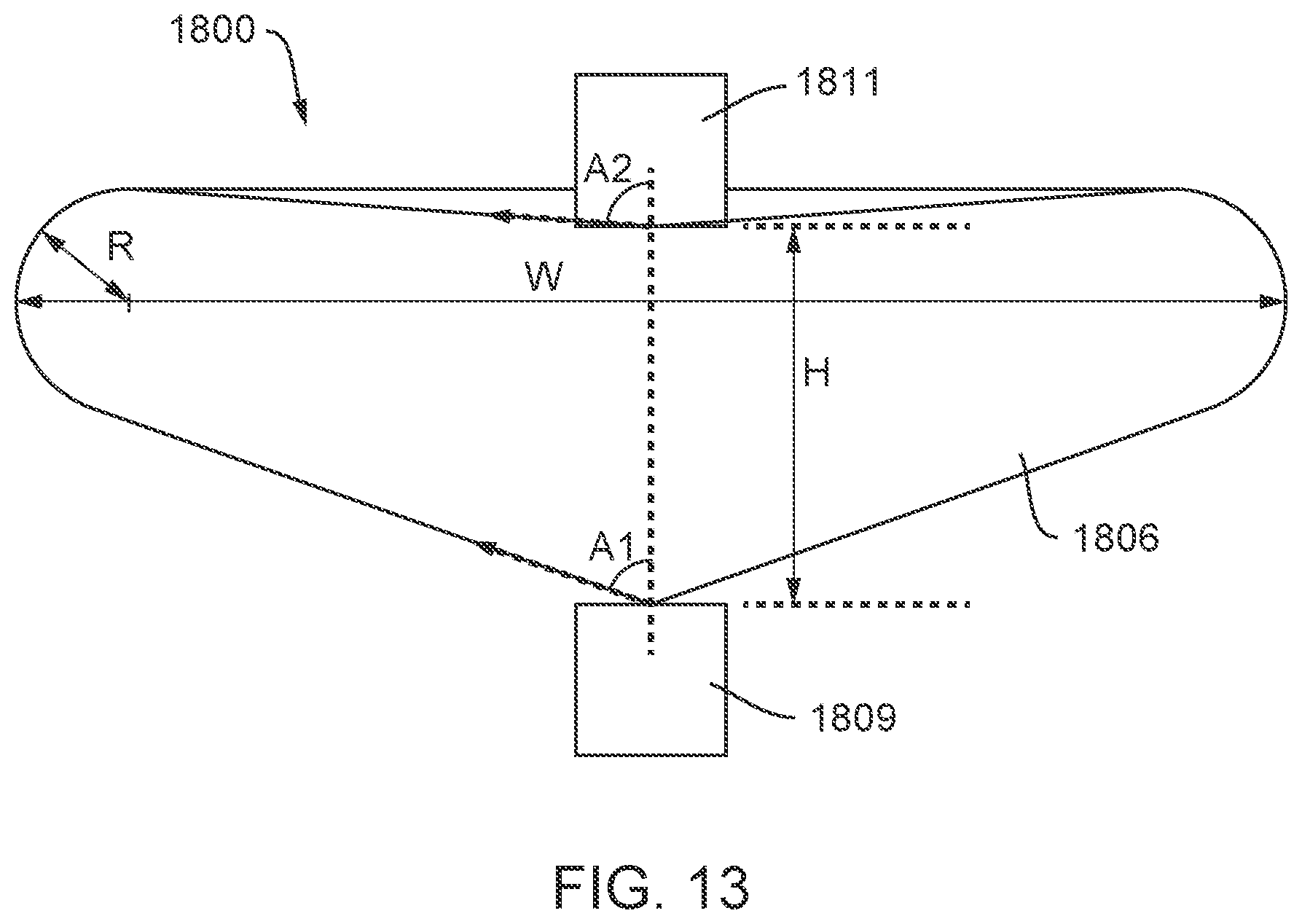
D00018

D00019

D00020

D00021

D00022
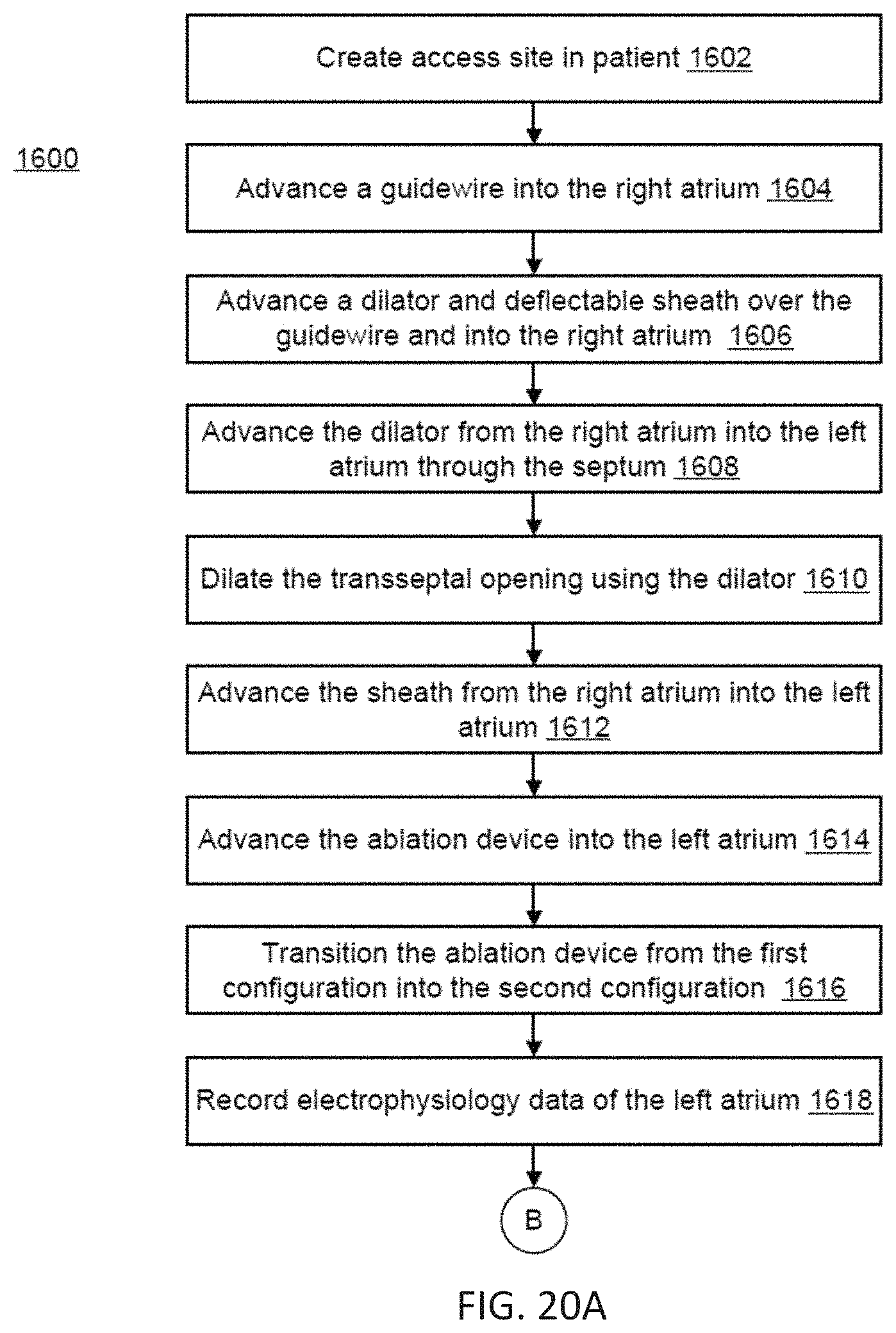
D00023

XML
uspto.report is an independent third-party trademark research tool that is not affiliated, endorsed, or sponsored by the United States Patent and Trademark Office (USPTO) or any other governmental organization. The information provided by uspto.report is based on publicly available data at the time of writing and is intended for informational purposes only.
While we strive to provide accurate and up-to-date information, we do not guarantee the accuracy, completeness, reliability, or suitability of the information displayed on this site. The use of this site is at your own risk. Any reliance you place on such information is therefore strictly at your own risk.
All official trademark data, including owner information, should be verified by visiting the official USPTO website at www.uspto.gov. This site is not intended to replace professional legal advice and should not be used as a substitute for consulting with a legal professional who is knowledgeable about trademark law.