Battery protection system
Kramer
U.S. patent number 10,686,180 [Application Number 15/834,373] was granted by the patent office on 2020-06-16 for battery protection system. This patent grant is currently assigned to Milwaukee Electric Tool Corporation. The grantee listed for this patent is MILWAUKEE ELECTRIC TOOL CORPORATION. Invention is credited to Scott G. Kramer.


View All Diagrams
| United States Patent | 10,686,180 |
| Kramer | June 16, 2020 |
Battery protection system
Abstract
A battery protection system for a power tool includes a power tool housing with a battery pack interface. The battery pack interface includes at least one tool electrical terminal. The battery protection system also includes a battery with a battery housing and at least one battery electrical terminal and a divider positioned between the at least one battery electrical terminal and the at least one tool electrical terminal. The divider includes at least one fold.
| Inventors: | Kramer; Scott G. (Brookfield, WI) | ||||||||||
|---|---|---|---|---|---|---|---|---|---|---|---|
| Applicant: |
|
||||||||||
| Assignee: | Milwaukee Electric Tool
Corporation (Brookfield, WI) |
||||||||||
| Family ID: | 62489656 | ||||||||||
| Appl. No.: | 15/834,373 | ||||||||||
| Filed: | December 7, 2017 |
Prior Publication Data
| Document Identifier | Publication Date | |
|---|---|---|
| US 20180166674 A1 | Jun 14, 2018 | |
Related U.S. Patent Documents
| Application Number | Filing Date | Patent Number | Issue Date | ||
|---|---|---|---|---|---|
| 62431962 | Dec 9, 2016 | ||||
| Current U.S. Class: | 1/1 |
| Current CPC Class: | B25F 5/02 (20130101); H01M 2/34 (20130101); H01M 2/1022 (20130101); H01M 2200/00 (20130101); H01M 2220/30 (20130101) |
| Current International Class: | H01M 2/34 (20060101); H01M 2/10 (20060101); B25F 5/02 (20060101) |
| Field of Search: | ;429/428 |
References Cited [Referenced By]
U.S. Patent Documents
| 4107765 | August 1978 | Singleton et al. |
| 4551028 | November 1985 | Rowan et al. |
| 5380602 | January 1995 | Kato et al. |
| 6329095 | December 2001 | Farnworth et al. |
| 6368287 | April 2002 | Hadas |
| 6389143 | May 2002 | Leedom et al. |
| 6410997 | June 2002 | Sjursen et al. |
| 6667936 | December 2003 | Ditzig |
| 6889840 | May 2005 | Schein et al. |
| 7190147 | March 2007 | Gileff et al. |
| 7267550 | September 2007 | Eckberg et al. |
| 7871720 | January 2011 | Myers et al. |
| 8086306 | December 2011 | Katzman et al. |
| 9077055 | July 2015 | Yau |
| 9189663 | November 2015 | Goren et al. |
| 9314900 | April 2016 | Vanko et al. |
| 2009/0321304 | December 2009 | Watson |
| 2011/0101780 | May 2011 | Johnson |
| 2014/0141309 | May 2014 | Suzuki |
| 2014/0355207 | December 2014 | Stephens et al. |
| 2016/0126533 | May 2016 | Velderman |
| 2016/0260958 | September 2016 | Weir et al. |
| 2016/0276678 | September 2016 | Jorgensen et al. |
| 2016/0329536 | November 2016 | Dorr et al. |
| 2015182050 | Dec 2015 | WO | |||
Attorney, Agent or Firm: Michael Best & Friedrich LLP
Parent Case Text
CROSS REFERENCE TO RELATED APPLICATIONS
This application claims priority to U.S. Provisional Patent Application No. 62/431,962 filed Dec. 9, 2016, the entire content of which is incorporated herein by reference.
Claims
What is claimed is:
1. A battery protection system for a power tool comprising: a power tool housing including a battery pack interface, the battery pack interface including at least one tool electrical terminal; a battery including a battery housing and at least one battery electrical terminal; and a divider positioned between the at least one battery electrical terminal and the at least one tool electrical terminal when the battery is coupled to the power tool, the divider including at least one fold.
2. The battery protection system of claim 1, wherein the divider is movable between a first position in which the at least one battery electrical terminal of the battery pack is galvanically isolated from the at least one tool electrical terminal of the battery pack interface and a second position in which the at least one battery electrical terminal of the battery pack and the at least one tool electrical terminal of the battery pack interface are electrically coupled.
3. The battery protection system of claim 2, wherein the divider further includes an indicator indicating to a user to move the divider from the first position to the second position before operation of the power tool.
4. The battery protection system of claim 1, wherein the at least one fold is one of a plurality of folds.
5. The battery protection system of claim 4, wherein the at least one tool electrical terminal of the battery pack interface is a first tool electrical terminal, and wherein the battery pack interface further includes a second tool electrical terminal and a third tool electrical terminal.
6. The battery protection system of claim 5, wherein the first tool electrical terminal is a positive terminal, the second tool electrical terminal is a ground terminal, and the third tool electrical terminal is a communication terminal.
7. The battery protection system of claim 5, wherein the plurality of folds include a first fold, a second fold, and a third fold.
8. The battery protection system of claim 7, wherein the at least one battery electrical terminal of the battery pack is a first battery electrical terminal, and wherein the battery pack further includes a second battery electrical terminal and a third battery electrical terminal.
9. The battery protection system of claim 8, wherein the first fold of the divider galvanically isolates the first battery electrical terminal from the first tool electrical terminal, the second fold of the divider galvanically isolates the second battery electrical terminal from the second tool electrical terminal, and the third fold of the divider galvanically isolates the third battery electrical terminal from the third tool electrical terminal.
10. The battery protection system of claim 9, wherein the first battery electrical terminal is a positive terminal, the second battery terminal is a ground terminal, and the third terminal is a communication terminal.
Description
FIELD
Embodiments relate to power tools, and more particularly, to a battery protection system for a power tool.
BACKGROUND
During shipping, battery packs may be physically connected to power tools within a kit. Although not in operation, when connected, the power tool may draw power from the battery packs. This connection during transport may result in the end user receiving a battery having low voltage and being inoperable.
SUMMARY
One embodiment provides a battery protection system for a power tool including a power tool housing including a battery pack interface. The battery pack interface includes at least one tool electrical terminal. The battery protection system also includes a battery with a battery housing and at least one battery electrical terminal and a divider positioned between the at least one battery electrical terminal and the at least one tool electrical terminal. The divider includes at least one fold.
Another embodiment provides a divider for a battery protection system of a power tool including a battery receptacle having a battery receptacle terminal, the battery receptacle configured to receive a battery pack having a battery pack terminal. The divider includes an outer portion with an indicator and an inner portion with a stem extending from the outer portion. The stem galvanically isolates the battery receptacle terminal and the battery pack terminal.
BRIEF DESCRIPTION OF THE DRAWINGS
FIG. 1 illustrates a perspective view of a power tool according to one embodiment.
FIG. 2 illustrates an enlarged perspective view of the power tool of FIG. 1 connected to a battery pack according to one embodiment.
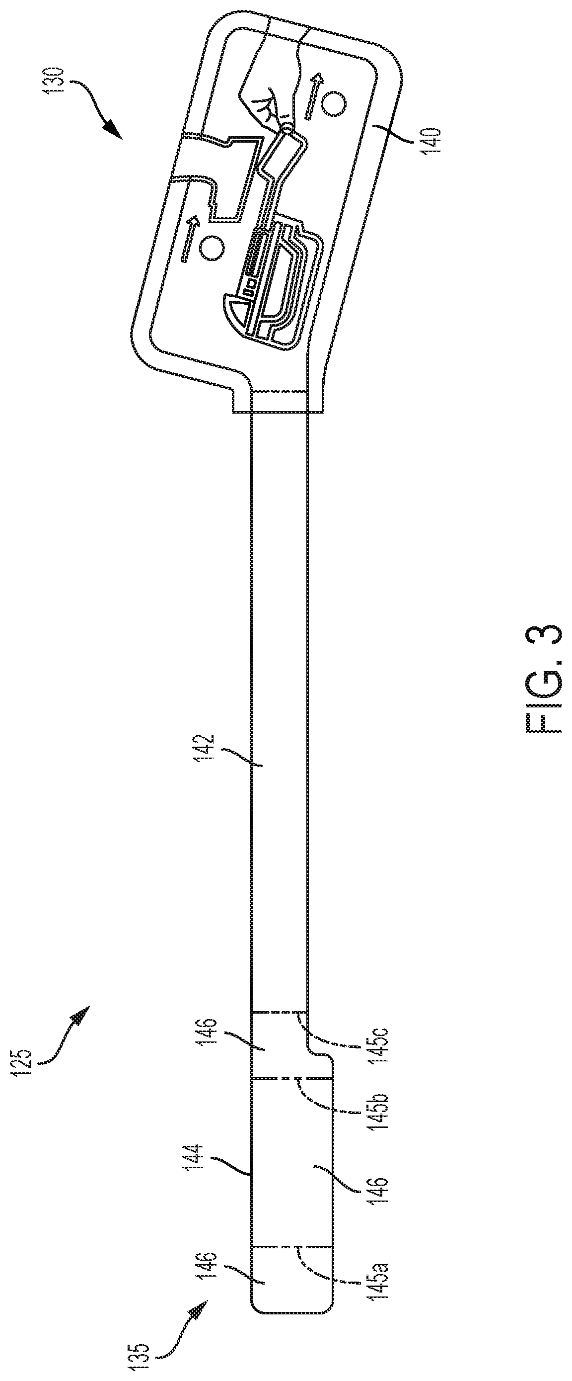
FIG. 3 illustrates a front view of a divider according to one embodiment.
FIG. 4 illustrates a perspective view of the divider of FIG. 3 in contact with a battery interface of the power tool of FIG. 1 according to one embodiment.
FIG. 5 illustrates the power tool of FIG. 1 without the divider according to one embodiment.
FIG. 6 illustrates a perspective view of the divider of FIG. 3 according to one embodiment.
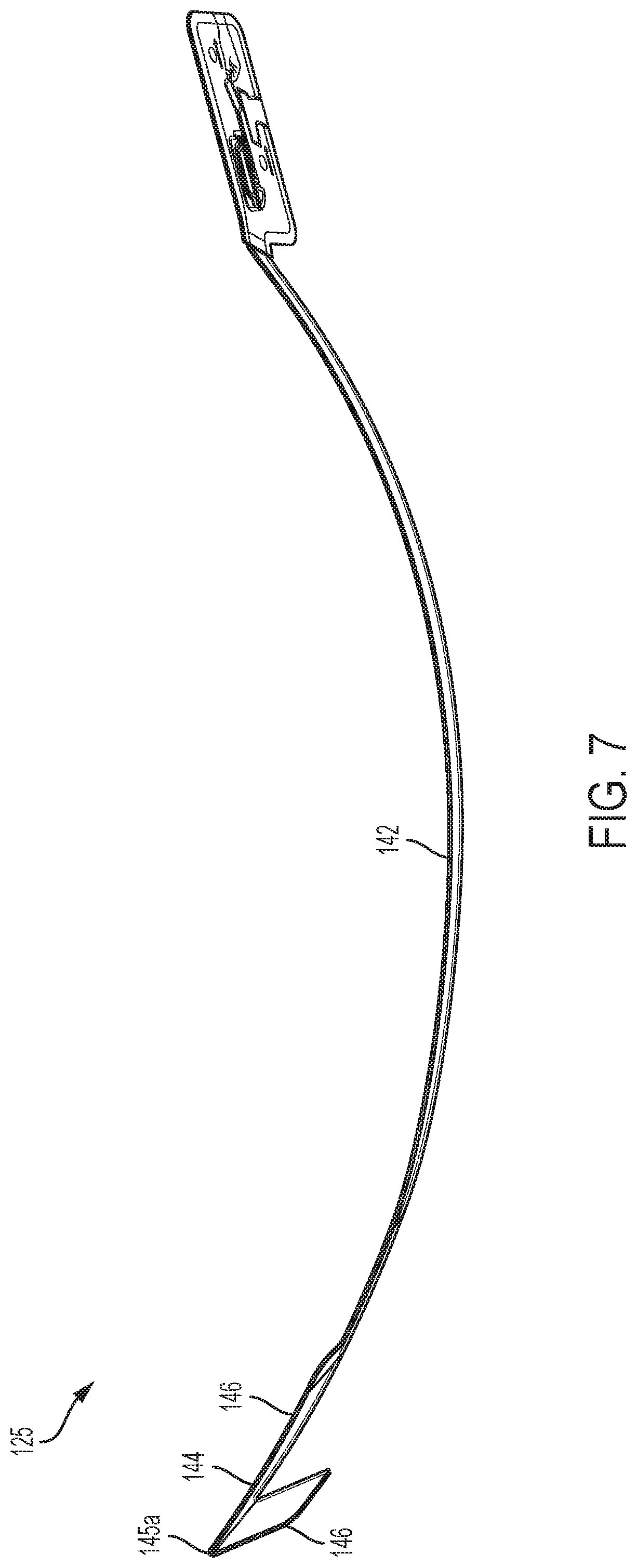
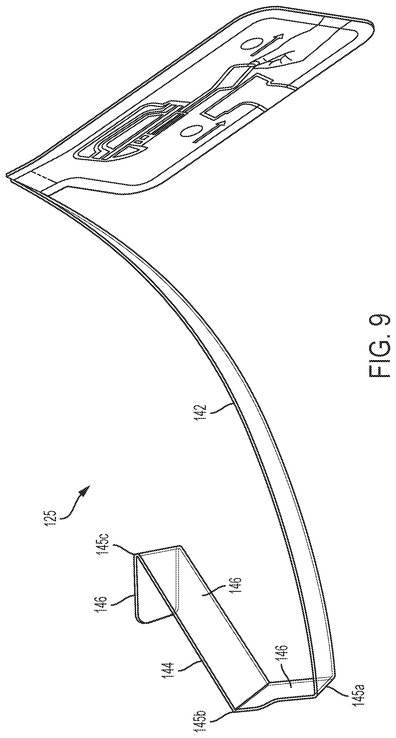
FIG. 7 illustrates a side view of the divider of FIG. 3 according to one embodiment.
FIG. 8 illustrates a side view of the divider of FIG. 3 according to one embodiment.
FIG. 9 illustrates a side view of the divider of FIG. 3 according to one embodiment.
FIG. 10 illustrates a top view of the divider of FIG. 3 in contact with a battery interface of the power tool according to one embodiment.
FIG. 11 illustrates a top view of the divider of FIG. 3 in contact with a battery interface of the power tool according to another embodiment.
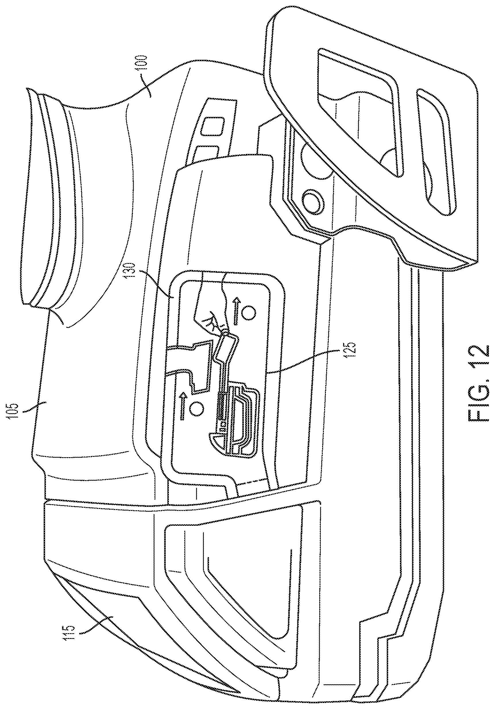
FIG. 12 illustrates a side perspective view of the divider of FIG. 3 placed between the power tool and battery pack of FIG. 2 according to one embodiment.
Before any embodiments of the invention are explained in detail, it is to be understood that the invention is not limited in its application to the details of construction and the arrangement of components set forth in the following description or illustrated in the following drawings. The invention is capable of other embodiments and of being practiced or of being carried out in various ways.
DETAILED DESCRIPTION
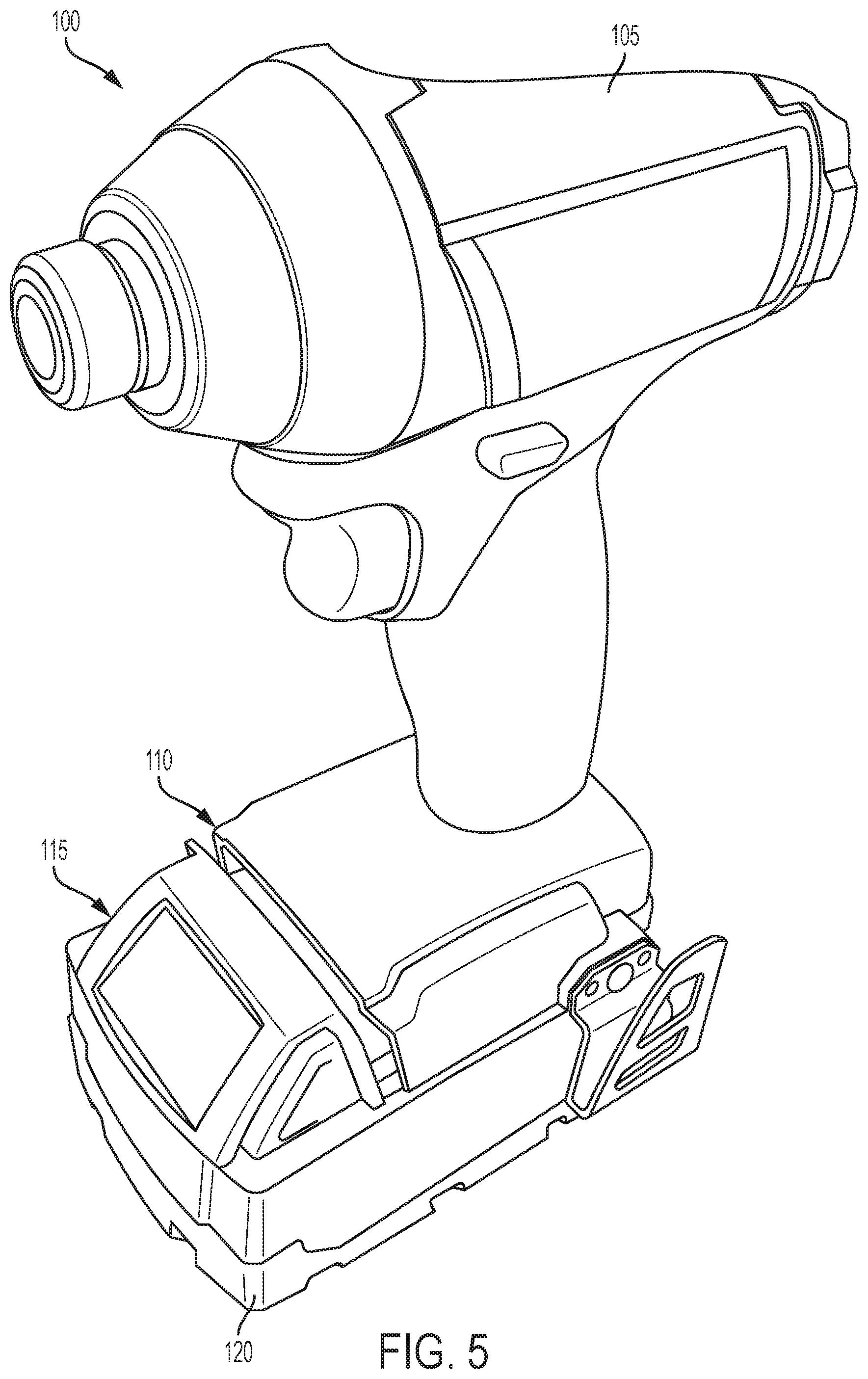
FIGS. 1 and 2 illustrate a power tool 100 according to one embodiment of the invention. Although illustrated as a power drill, in other embodiments, the power tool 100 may be another power tool and/or outdoor tool, for example but not limited to, a miter saw, a rotary hammer, a power saw, a chainsaw, a leaf blower, and a string trimmer.
The power tool 100 includes a power tool housing 105 having a battery pack interface 110 to physically and electrically connect to a battery pack 115 having a battery pack housing 120. In some embodiments, the battery pack interface 110 includes a positive tool terminal, a ground tool terminal, and a communication tool terminal, hereinafter the tool terminals, for electrically connecting to a positive battery terminal, a ground battery terminal, and a communication battery terminal of the battery pack 115, hereinafter the battery terminals. Although illustrated as a rail and groove interface, in other embodiments, the battery pack interface 110 may be a receptacle and stem interface. In further embodiments, the battery pack interface 110 may be a battery receptacle to receive a battery.
A divider 125 is placed between the power tool housing 105 and the battery pack housing 120 at the battery pack interface 110. In the illustrated embodiment, the divider 125, when placed between the power tool housing 105 and the battery pack housing 120, electrically isolates at least one of the tool terminals from at least one of the battery terminals. In some embodiments, the divider 125 may isolate all the tool terminals from the battery terminals.
FIG. 3 illustrates a front view of the divider 125. The divider 125 includes an outer portion 130 and an inner portion 135. The outer portion 130 further includes an indicator 140 that provides an indication, or instructions, to a user. For example, the instructions may inform the user that the divider 125 should be removed before use of power tool 100. The inner portion 135, when positioned between the power tool 100 and the battery pack 115, prevents direct contact between at least one of the tool terminals and at least one of the battery terminals. The inner portion 135 includes a long stem 142 with an increased width portion 144. The increased width portion 144 includes one or more folds 145a, 145b, and 145c. In further embodiments, the divider 125 may include fewer or more folds that define fewer or more sections 146 between the folds 145a, 145b, 145c of the divider 125. For example, the divider 125 may include additional folds defining additional sections so that the divider 125 may isolate additional tool terminals from the battery terminals as discussed below.
FIG. 4 illustrates the divider 125 in contact with a tool terminal 150a of the power tool housing 105. The tool terminal 150a may be the positive tool terminal, the ground tool terminal, or the communication tool terminal. In the illustrated embodiment, the divider 125 is placed in contact with the power tool housing 105, with the fold 145c substantially covering the tool terminal 150a, thus providing electrical isolation between the tool terminal 150a and at least one battery terminal when the battery pack 115 is connected to the power tool 100. In another embodiment, the divider 125 is placed in contact with a battery terminal of the battery pack housing 120. The battery terminal may be the positive battery terminal, the ground battery terminal, or the communication battery terminal. In such an embodiment, the fold 145c substantially covers the battery terminal, thus providing electrical isolation between the tool terminal 150a and at least one battery terminal when the battery pack 115 is connected to the power tool 100.
The divider 125 creates a galvanic isolation between at least one of the tool terminals and at least one of the battery terminals. The galvanic isolation allows signals to pass between at least one of the tool terminals and at least one of the battery terminals, however, stray currents, such as differences in ground potential or currents induced by AC/DC power, are blocked. As such, the divider 125 prevents draw of current from the battery pack 115 before the power tool 100 is ready for use. In some embodiments, the divider 125 may be used to isolate one of the tool terminals from the battery terminals while the power tool 100 is in its original packaging that way the power tool 100 does not draw current from the battery pack 115 while the power tool 100 is being shipped or while on a store shelf before being sold.
FIG. 5 illustrates the power tool 100 without the divider 125. Once the power tool 100 is ready for use, the divider 125 can be removed from the battery pack interface 110 without removing the battery pack 115. A user pulls the divider 125 from the battery pack interface 110 removing the galvanic isolation and allowing the power tool 100 to draw power from the battery pack 115.
FIGS. 6-9 illustrate perspective views of the divider 125 with a varying amount of folds. For example, FIG. 6 illustrates the divider 125 with no folds. FIG. 7 illustrates the divider 125 with a first fold 145a in the stem 142. FIG. 8 illustrates the divider 125 with a first fold 145a and a second fold 145b in the stem 142. FIG. 9 illustrates the divider 125 with a first fold 145a, a second fold 145b, and a third fold 145c.
As illustrated in FIG. 10, the divider 125 is covering the tool terminal 150a. The first and second folds 145a, 145b are positioned within a recess 155 of the battery pack interface 110 and the third fold 145c is positioned over the tool terminal 150a so that the tool terminal 150a is galvanically isolated from a battery terminal when the battery pack 115 is installed on the tool housing 105.
With reference to FIG. 11, in some embodiments, the divider 125 includes multiple folds 145a, 145b, that cover multiple tool terminals 150a, 150b. A first fold 145a substantially covers a tool terminal 150a, thus providing galvanic isolation between the tool terminal 150a and at least one battery terminal when the battery pack 115 is connected to the power tool 100. A second fold 145b substantially covers a tool terminal 150a, thus providing galvanic isolation between the tool terminal 150b and at least one battery terminal when the battery pack 115 is connected to the power tool 100.
FIG. 12 illustrates the power tool 100 with the battery pack 115 coupled to the battery pack interface 110 of the tool housing 105 with the divider 125 positioned in a first position. In the first position, the inner portion 135 of the divider 125 is positioned between the battery pack interface 110 and the battery pack 115. The outer portion 130 of the divider 125 is positioned outside the tool housing 105 so that a user may pull the outer portion 130 out of the tool housing 105 to electrical connect the battery pack 115 to the power tool 100.
Various features of the invention are set forth in the following claims.
* * * * *
D00000
D00001
D00002
D00003
D00004
D00005
D00006
D00007
D00008
D00009
D00010
D00011
D00012
XML
uspto.report is an independent third-party trademark research tool that is not affiliated, endorsed, or sponsored by the United States Patent and Trademark Office (USPTO) or any other governmental organization. The information provided by uspto.report is based on publicly available data at the time of writing and is intended for informational purposes only.
While we strive to provide accurate and up-to-date information, we do not guarantee the accuracy, completeness, reliability, or suitability of the information displayed on this site. The use of this site is at your own risk. Any reliance you place on such information is therefore strictly at your own risk.
All official trademark data, including owner information, should be verified by visiting the official USPTO website at www.uspto.gov. This site is not intended to replace professional legal advice and should not be used as a substitute for consulting with a legal professional who is knowledgeable about trademark law.