Vehicular driver assist system
Chundrlik, Jr. , et al.
U.S. patent number 10,685,243 [Application Number 16/105,218] was granted by the patent office on 2020-06-16 for vehicular driver assist system. This patent grant is currently assigned to MAGNA ELECTRONICS INC.. The grantee listed for this patent is MAGNA ELECTRONICS INC.. Invention is credited to William J. Chundrlik, Jr., Dominik Raudszus, Christopher L. Van Dan Elzen.


View All Diagrams
| United States Patent | 10,685,243 |
| Chundrlik, Jr. , et al. | June 16, 2020 |
Vehicular driver assist system
Abstract
A vehicular driver assistance system includes a camera disposed at a vehicle and a control having an image processor that processes image data captured by the camera to determine lane markings demarcating a traffic lane in which the vehicle is traveling and to estimate a path of travel for the vehicle to maintain the vehicle in the traffic lane in which the vehicle is traveling in situations where the lane markings demarcating the traffic lane in which the vehicle is traveling are not readily determinable. The control estimates the path of travel for the vehicle at least responsive to vehicle information. The system updates the estimated path of travel ahead of the vehicle even when no lane markings are determined present on the road ahead of the vehicle. The control adjusts processing of captured image data responsive at least in part to a driving situation that the vehicle is in.
| Inventors: | Chundrlik, Jr.; William J. (Rochester Hills, MI), Raudszus; Dominik (Aachen, DE), Van Dan Elzen; Christopher L. (Rochester, MI) | ||||||||||
|---|---|---|---|---|---|---|---|---|---|---|---|
| Applicant: |
|
||||||||||
| Assignee: | MAGNA ELECTRONICS INC. (Auburn
Hills, MI) |
||||||||||
| Family ID: | 59786686 | ||||||||||
| Appl. No.: | 16/105,218 | ||||||||||
| Filed: | August 20, 2018 |
Prior Publication Data
| Document Identifier | Publication Date | |
|---|---|---|
| US 20190005339 A1 | Jan 3, 2019 | |
Related U.S. Patent Documents
| Application Number | Filing Date | Patent Number | Issue Date | ||
|---|---|---|---|---|---|
| 15446221 | Mar 1, 2017 | 10055651 | |||
| 62305216 | Mar 8, 2016 | ||||
| Current U.S. Class: | 1/1 |
| Current CPC Class: | G08G 1/165 (20130101); G08G 1/167 (20130101); G06K 9/00798 (20130101); G08G 1/166 (20130101); B60R 1/00 (20130101); G08G 1/0962 (20130101); B60R 2300/302 (20130101); B60R 2300/607 (20130101); B60R 2300/804 (20130101); B60R 2300/8093 (20130101) |
| Current International Class: | G06K 9/00 (20060101); G08G 1/16 (20060101); G08G 1/0962 (20060101); B60R 1/00 (20060101) |
References Cited [Referenced By]
U.S. Patent Documents
| 5168378 | December 1992 | Black |
| 5170374 | December 1992 | Shimohigashi et al. |
| 5172235 | December 1992 | Wilm et al. |
| 5177685 | January 1993 | Davis et al. |
| 5182502 | January 1993 | Slotkowski et al. |
| 5184956 | February 1993 | Langlais et al. |
| 5189561 | February 1993 | Hong |
| 5193000 | March 1993 | Lipton et al. |
| 5289182 | February 1994 | Brillard et al. |
| 5289321 | February 1994 | Secor |
| 5305012 | April 1994 | Faris |
| 5307136 | April 1994 | Saneyoshi |
| 5309137 | May 1994 | Kajiwara |
| 5313072 | May 1994 | Vachss |
| 5325096 | June 1994 | Pakett |
| 5325386 | June 1994 | Jewell et al. |
| 5329206 | July 1994 | Slotkowski et al. |
| 5331312 | July 1994 | Kudoh |
| 5336980 | August 1994 | Levers |
| 5341437 | August 1994 | Nakayama |
| 5351044 | September 1994 | Mathur et al. |
| 5355118 | October 1994 | Fukuhara |
| 5374852 | December 1994 | Parkes |
| 5386285 | January 1995 | Asayama |
| 5394333 | February 1995 | Kao |
| 5410346 | April 1995 | Saneyoshi et al. |
| 5414257 | May 1995 | Stanton |
| 5414461 | May 1995 | Kishi et al. |
| 5416478 | May 1995 | Morinaga |
| 5424952 | June 1995 | Asayama |
| 5426294 | June 1995 | Kobayashi et al. |
| 5430431 | July 1995 | Nelson |
| 5434407 | July 1995 | Bauer et al. |
| 5440428 | August 1995 | Hegg et al. |
| 5444478 | August 1995 | Lelong et al. |
| 5451822 | September 1995 | Bechtel et al. |
| 5457493 | October 1995 | Leddy et al. |
| 5461357 | October 1995 | Yoshioka et al. |
| 5461361 | October 1995 | Moore |
| 5469298 | November 1995 | Suman et al. |
| 5471515 | November 1995 | Fossum et al. |
| 5475494 | December 1995 | Nishida et al. |
| 5498866 | March 1996 | Bendicks et al. |
| 5500766 | March 1996 | Stonecypher |
| 5510983 | April 1996 | Lino |
| 5515448 | May 1996 | Nishitani |
| 5521633 | May 1996 | Nakajima et al. |
| 5528698 | June 1996 | Kamei et al. |
| 5529138 | June 1996 | Shaw et al. |
| 5530240 | June 1996 | Larson et al. |
| 5530420 | June 1996 | Tsuchiya et al. |
| 5535314 | July 1996 | Alves et al. |
| 5537003 | July 1996 | Bechtel et al. |
| 5539397 | July 1996 | Asanuma et al. |
| 5541590 | July 1996 | Nishio |
| 5550677 | August 1996 | Schofield et al. |
| 5555555 | September 1996 | Sato et al. |
| 5568027 | October 1996 | Teder |
| 5574443 | November 1996 | Hsieh |
| 5581464 | December 1996 | Woll et al. |
| 5594222 | January 1997 | Caldwell |
| 5610756 | March 1997 | Lynam et al. |
| 5614788 | March 1997 | Mullins |
| 5619370 | April 1997 | Guinosso |
| 5632092 | May 1997 | Blank et al. |
| 5634709 | June 1997 | Iwama |
| 5642299 | June 1997 | Hardin et al. |
| 5648835 | July 1997 | Uzawa |
| 5650944 | July 1997 | Kise |
| 5660454 | August 1997 | Mori et al. |
| 5661303 | August 1997 | Teder |
| 5666028 | September 1997 | Bechtel et al. |
| 5670935 | September 1997 | Schofield et al. |
| 5677851 | October 1997 | Kingdon et al. |
| 5699044 | December 1997 | Van Lente et al. |
| 5724316 | March 1998 | Brunts |
| 5732379 | March 1998 | Eckert et al. |
| 5737226 | April 1998 | Olson et al. |
| 5760828 | June 1998 | Cortes |
| 5760931 | June 1998 | Saburi et al. |
| 5760962 | June 1998 | Schofield et al. |
| 5761094 | June 1998 | Olson et al. |
| 5765116 | June 1998 | Wilson-Jones |
| 5765118 | June 1998 | Fukatani |
| 5781437 | July 1998 | Wiemer et al. |
| 5790403 | August 1998 | Nakayama |
| 5790973 | August 1998 | Blaker et al. |
| 5793308 | August 1998 | Rosinski et al. |
| 5793420 | August 1998 | Schmidt |
| 5796094 | August 1998 | Schofield et al. |
| 5837994 | November 1998 | Stam et al. |
| 5844505 | December 1998 | Van Ryzin |
| 5844682 | December 1998 | Kiyomoto et al. |
| 5845000 | December 1998 | Breed et al. |
| 5848802 | December 1998 | Breed et al. |
| 5850176 | December 1998 | Kinoshita et al. |
| 5850254 | December 1998 | Takano et al. |
| 5867591 | February 1999 | Onda |
| 5877707 | March 1999 | Kowalick |
| 5877897 | March 1999 | Schofield et al. |
| 5878357 | March 1999 | Sivashankar et al. |
| 5878370 | March 1999 | Olson |
| 5883739 | March 1999 | Ashihara et al. |
| 5884212 | March 1999 | Lion |
| 5890021 | March 1999 | Onoda |
| 5896085 | April 1999 | Mori et al. |
| 5899956 | May 1999 | Chan |
| 5915800 | June 1999 | Hiwatashi et al. |
| 5923027 | July 1999 | Stam et al. |
| 5924212 | July 1999 | Domanski |
| 5929786 | July 1999 | Schofield et al. |
| 5949331 | September 1999 | Schofield et al. |
| 5959555 | September 1999 | Furuta |
| 5963247 | October 1999 | Banitt |
| 5990469 | November 1999 | Bechtel et al. |
| 5990649 | November 1999 | Nagao et al. |
| 6020704 | February 2000 | Buschur |
| 6049171 | April 2000 | Stam et al. |
| 6097024 | August 2000 | Stam et al. |
| 6144022 | November 2000 | Tenenbaum et al. |
| 6175300 | January 2001 | Kendrick |
| 6178034 | January 2001 | Allemand et al. |
| 6185492 | February 2001 | Kagawa et al. |
| 6223114 | April 2001 | Boros et al. |
| 6266082 | July 2001 | Yonezawa et al. |
| 6266442 | July 2001 | Laumeyer et al. |
| 6285393 | September 2001 | Shimoura et al. |
| 6297781 | October 2001 | Turnbull et al. |
| 6302545 | October 2001 | Schofield et al. |
| 6310611 | October 2001 | Caldwell |
| 6317057 | November 2001 | Lee |
| 6320282 | November 2001 | Caldwell |
| 6333759 | December 2001 | Mazzilli |
| 6353392 | March 2002 | Schofield et al. |
| 6370329 | April 2002 | Teuchert |
| 6392315 | May 2002 | Jones et al. |
| 6396397 | May 2002 | Bos et al. |
| 6420975 | July 2002 | DeLine et al. |
| 6424273 | July 2002 | Gutta et al. |
| 6430303 | August 2002 | Naoi et al. |
| 6442465 | August 2002 | Breed et al. |
| 6477464 | November 2002 | McCarthy et al. |
| 6487501 | November 2002 | Jeon |
| 6497503 | December 2002 | Dassanayake et al. |
| 6498620 | December 2002 | Schofield et al. |
| 6516664 | February 2003 | Lynam |
| 6539306 | March 2003 | Turnbull |
| 6547133 | April 2003 | Devries, Jr. et al. |
| 6553130 | April 2003 | Lemelson et al. |
| 6559435 | May 2003 | Schofield et al. |
| 6574033 | June 2003 | Chui et al. |
| 6589625 | July 2003 | Kothari et al. |
| 6594583 | July 2003 | Ogura et al. |
| 6611202 | August 2003 | Schofield et al. |
| 6611610 | August 2003 | Stam et al. |
| 6636258 | October 2003 | Strumolo |
| 6672731 | January 2004 | Schnell et al. |
| 6678614 | January 2004 | McCarthy et al. |
| 6690268 | February 2004 | Schofield et al. |
| 6700605 | March 2004 | Toyoda et al. |
| 6704621 | March 2004 | Stein et al. |
| 6711474 | March 2004 | Treyz et al. |
| 6714331 | March 2004 | Lewis et al. |
| 6735506 | May 2004 | Breed et al. |
| 6744353 | June 2004 | Sjonell |
| 6762867 | July 2004 | Lippert et al. |
| 6795221 | September 2004 | Urey |
| 6802617 | October 2004 | Schofield et al. |
| 6806452 | October 2004 | Bos et al. |
| 6819231 | November 2004 | Berberich et al. |
| 6822563 | November 2004 | Bos et al. |
| 6823241 | November 2004 | Shirato et al. |
| 6824281 | November 2004 | Schofield et al. |
| 6889161 | May 2005 | Winner et al. |
| 6891563 | May 2005 | Schofield et al. |
| 6909753 | June 2005 | Meehan et al. |
| 6946978 | September 2005 | Schofield |
| 6953253 | October 2005 | Schofield et al. |
| 6968736 | November 2005 | Lynam |
| 6975775 | December 2005 | Rykowski et al. |
| 6989736 | January 2006 | Berberich et al. |
| 7004606 | February 2006 | Schofield |
| 7005974 | February 2006 | McMahon et al. |
| 7038577 | May 2006 | Pawlicki et al. |
| 7062300 | June 2006 | Kim |
| 7065432 | June 2006 | Moisel et al. |
| 7079017 | July 2006 | Lang et al. |
| 7085637 | August 2006 | Breed et al. |
| 7092548 | August 2006 | Laumeyer et al. |
| 7111968 | September 2006 | Bauer et al. |
| 7116246 | October 2006 | Winter et al. |
| 7123168 | October 2006 | Schofield |
| 7145519 | December 2006 | Takahashi et al. |
| 7149613 | December 2006 | Stam et al. |
| 7161616 | January 2007 | Okamoto et al. |
| 7167796 | January 2007 | Taylor et al. |
| 7195381 | March 2007 | Lynam et al. |
| 7202776 | April 2007 | Breed |
| 7205904 | April 2007 | Schofield |
| 7227459 | June 2007 | Bos et al. |
| 7227611 | June 2007 | Hull et al. |
| 7311406 | December 2007 | Schofield et al. |
| 7325934 | February 2008 | Schofield et al. |
| 7325935 | February 2008 | Schofield et al. |
| 7338177 | March 2008 | Lynam |
| 7355524 | April 2008 | Schofield |
| 7355526 | April 2008 | Huang |
| 7380948 | June 2008 | Schofield et al. |
| 7388182 | June 2008 | Schofield et al. |
| 7400236 | July 2008 | Kade et al. |
| 7424364 | September 2008 | Gem et al. |
| 7425076 | September 2008 | Schofield et al. |
| 7446650 | November 2008 | Scholfield et al. |
| 7460951 | December 2008 | Altan |
| 7480149 | January 2009 | DeWard et al. |
| 7490007 | February 2009 | Taylor et al. |
| 7492281 | February 2009 | Lynam et al. |
| 7510038 | March 2009 | Kaufmann et al. |
| 7526103 | April 2009 | Schofield et al. |
| 7532981 | May 2009 | Kataoka et al. |
| 7561032 | July 2009 | Huang et al. |
| 7561181 | July 2009 | Schofield et al. |
| 7581859 | September 2009 | Lynam |
| 7592928 | September 2009 | Chinomi et al. |
| 7616781 | November 2009 | Schofield et al. |
| 7619508 | November 2009 | Lynam et al. |
| 7639149 | December 2009 | Katoh |
| 7681960 | March 2010 | Wanke et al. |
| 7711464 | May 2010 | Kaufmann |
| 7720580 | May 2010 | Higgins-Luthman |
| 7777611 | August 2010 | Desai |
| 7881496 | February 2011 | Camilleri et al. |
| 7885730 | February 2011 | Kaufmann et al. |
| 7914187 | March 2011 | Higgins-Luthman et al. |
| 8027029 | September 2011 | Lu et al. |
| 8164628 | April 2012 | Stein et al. |
| 8670903 | March 2014 | Lee et al. |
| 8694224 | April 2014 | Chundrlik, Jr. et al. |
| 8818606 | August 2014 | Lee et al. |
| 8930081 | January 2015 | Bolourchi et al. |
| 8965633 | February 2015 | Lee et al. |
| 9120486 | September 2015 | Mallinger |
| 9180908 | November 2015 | Van Dan Elzen et al. |
| 9264673 | February 2016 | Chundrlik, Jr. et al. |
| 10055651 | August 2018 | Chundrlik, Jr. et al. |
| 2002/0113873 | August 2002 | Williams |
| 2003/0137586 | July 2003 | Lewellen |
| 2003/0222982 | December 2003 | Hamdan et al. |
| 2004/0098197 | May 2004 | Matsumoto et al. |
| 2004/0107035 | June 2004 | Tange et al. |
| 2004/0114381 | June 2004 | Salmeen et al. |
| 2004/0128065 | July 2004 | Taylor et al. |
| 2004/0183663 | September 2004 | Shimakage |
| 2004/0200948 | October 2004 | Bos et al. |
| 2004/0230375 | November 2004 | Matsumoto et al. |
| 2004/0252020 | December 2004 | Matsumoto et al. |
| 2005/0015203 | January 2005 | Nishira |
| 2005/0078389 | April 2005 | Kulas et al. |
| 2005/0107931 | May 2005 | Shimakage et al. |
| 2005/0125153 | June 2005 | Matsumoto et al. |
| 2005/0264891 | December 2005 | Uken et al. |
| 2006/0018511 | January 2006 | Stam et al. |
| 2006/0018512 | January 2006 | Stam et al. |
| 2006/0050018 | March 2006 | Hutzel et al. |
| 2006/0091813 | May 2006 | Stam et al. |
| 2006/0103727 | May 2006 | Tseng |
| 2006/0250501 | November 2006 | Wildmann et al. |
| 2007/0091173 | April 2007 | Kade et al. |
| 2007/0104476 | May 2007 | Yasutomi et al. |
| 2007/0176080 | August 2007 | Schofield et al. |
| 2008/0061952 | March 2008 | Maass |
| 2008/0091318 | April 2008 | Deng et al. |
| 2008/0180529 | July 2008 | Taylor et al. |
| 2008/0183342 | July 2008 | Kaufmann et al. |
| 2009/0113509 | April 2009 | Tseng et al. |
| 2009/0132125 | May 2009 | Yonezawa et al. |
| 2009/0234553 | September 2009 | Sekiguchi |
| 2009/0243824 | October 2009 | Peterson et al. |
| 2009/0244361 | October 2009 | Gebauer et al. |
| 2009/0299573 | December 2009 | Thrun et al. |
| 2010/0020170 | January 2010 | Higgins-Luthman et al. |
| 2010/0045797 | February 2010 | Schofield et al. |
| 2010/0082195 | April 2010 | Lee et al. |
| 2010/0097469 | April 2010 | Blank et al. |
| 2010/0114431 | May 2010 | Switkes et al. |
| 2010/0121532 | May 2010 | Urai et al. |
| 2010/0228420 | September 2010 | Lee |
| 2010/0228437 | September 2010 | Hanzawa et al. |
| 2010/0231718 | September 2010 | Nakamori et al. |
| 2010/0295668 | November 2010 | Kataoka |
| 2011/0231095 | September 2011 | Nakada et al. |
| 2012/0057757 | March 2012 | Oyama |
| 2012/0062743 | March 2012 | Lynam et al. |
| 2012/0221168 | August 2012 | Zeng et al. |
| 2012/0316730 | December 2012 | Zhang et al. |
| 2013/0173115 | July 2013 | Gunia et al. |
| 2013/0231825 | September 2013 | Chundrlik, Jr. et al. |
| 2013/0231830 | September 2013 | Van Dan Elzen et al. |
| 2013/0253767 | September 2013 | Lee et al. |
| 2014/0176716 | June 2014 | Wallat et al. |
| 2015/0353085 | December 2015 | Lee |
| 2016/0046290 | February 2016 | Aharony |
| 2017/0323493 | November 2017 | Chundrlik, Jr. et al. |
Attorney, Agent or Firm: Honigman LLP
Parent Case Text
CROSS REFERENCE TO RELATED APPLICATIONS
The present application is a continuation of U.S. patent application Ser. No. 15/446,221, filed Mar. 1, 2017, now U.S. Pat. No. 10,055,651, which claims the filing benefits of U.S. provisional application Ser. No. 62/305,216, filed Mar. 8, 2016, which is hereby incorporated herein by reference in its entirety.
Claims
The invention claimed is:
1. A driver assistance system for a vehicle, said driver assistance system comprising: a camera disposed at a vehicle and having a field of view forward of the vehicle; a control comprising an image processor that is operable to process image data captured by said camera; wherein, responsive to processing by said image processor of image data captured by said camera, said control determines lane markings demarcating a traffic lane in which the vehicle is traveling; wherein, responsive to processing by said image processor of image data captured by said camera and responsive to a location input from a global positioning system to said control, said control estimates a path of travel for the vehicle to maintain the vehicle in the traffic lane in which the vehicle is traveling in situations where the lane markings demarcating the traffic lane in which the vehicle is traveling are not readily determinable; wherein said control estimates the path of travel for the vehicle at least responsive to vehicle information, and wherein the vehicle information comprises at least one selected from the group consisting of (i) vehicle speed, (ii) vehicle differential wheel speeds and (iii) vehicle yaw rate; wherein said driver assistance system updates the estimated path of travel ahead of the vehicle even when no lane markings are determined present on the road ahead of the vehicle; wherein said control adjusts processing by said image processor of image data captured by said camera responsive at least in part to a driving situation that the vehicle is in; and wherein the driving situation comprises at least one driving situation selected from the group consisting of (i) the vehicle cresting a hill, (ii) the vehicle crossing an intersection, (iii) the vehicle passing an entrance ramp and (iv) the vehicle passing an exit ramp.
2. The driver assistance system of claim 1, wherein, responsive to processing by said image processor of image data captured by said camera, said control estimates the path of travel for the vehicle to maintain the vehicle in the traffic lane in which the vehicle is traveling in situations where the lane markings demarcating the traffic lane in which the vehicle is traveling are lost by said camera for a period of time.
3. The driver assistance system of claim 1, wherein, responsive to processing by said image processor of image data captured by said camera, said control estimates the path of travel for the vehicle to maintain the vehicle in the traffic lane in which the vehicle is traveling in situations where the lane markings demarcating the traffic lane in which the vehicle is traveling are lost by said camera as the vehicle crosses an intersection.
4. The driver assistance system of claim 1, wherein, responsive to processing by said image processor of image data captured by said camera, said control estimates the path of travel for the vehicle to maintain the vehicle in the traffic lane in which the vehicle is traveling in situations where lane markings are erroneously determined by processing by said image processor of captured image data alone.
5. The driver assistance system of claim 1, wherein, responsive to processing by said image processor of image data captured by said camera, said control estimates the path of travel for the vehicle to maintain the vehicle in the traffic lane in which the vehicle is traveling in situations where processing by said image processor of image data alone determines lane markings that are not demarcating the traffic lane in which the vehicle is traveling.
6. The driver assistance system of claim 1, wherein said control estimates the path of travel for the vehicle at least in part responsive to a location input from a global positioning system to said control that provides the vehicle's current geographical location information.
7. The driver assistance system of claim 1, wherein said control estimates the path of travel for the vehicle at least in part responsive to a map input from a digital map to said control that provides road information pertaining to the road along which the vehicle is traveling.
8. The driver assistance system of claim 1, wherein, responsive to processing by said image processor of image data captured by said camera and responsive to a map input from a digital map to said control, said control estimates the path of travel for the vehicle to maintain the vehicle in the traffic lane in which the vehicle is traveling in situations where the lane markings demarcating the traffic lane in which the vehicle is traveling are not readily determinable.
9. A driver assistance system for a vehicle, said driver assistance system comprising: a camera disposed at a vehicle and having a field of view forward of the vehicle; a control comprising an image processor that is operable to process image data captured by said camera; wherein, responsive to processing by said image processor of image data captured by said camera, said control determines lane markings demarcating a traffic lane in which the vehicle is traveling; wherein, responsive to processing by said image processor of image data captured by said camera and responsive to at least one input selected from the group consisting of (i) a map input from a digital map to said control and (ii) a location input from a global positioning system to said control, said control estimates a path of travel for the vehicle to maintain the vehicle in the traffic lane in which the vehicle is traveling in situations where the lane markings demarcating the traffic lane in which the vehicle is traveling are not readily determinable; wherein, responsive to processing by said image processor ofimage data captured by said camera and responsive to the location input from the global positioning system to said control, said control estimates the path of travel for the vehicle to maintain the vehicle in the traffic lane in which the vehicle is traveling in situations where the lane markings demarcating the traffic lane in which the vehicle is traveling are not readily determinable; wherein said control estimates the path of travel for the vehicle at least responsive to vehicle information, and wherein the vehicle information comprises at least one selected from the group consisting of (i) vehicle speed, (ii) vehicle differential wheel speeds and (iii) vehicle yaw rate; wherein said control estimates the path of travel for the vehicle at least in part responsive to a location input from a global positioning system to said control that provides the vehicle's current geographical location information; wherein said driver assistance system updates the estimated path of travel ahead of the vehicle even when no lane markings are determined present on the road ahead of the vehicle; wherein said control adjusts processing by said image processor of image data captured by said camera responsive at least in part to a driving situation that the vehicle is in; and wherein the driving situation comprises at least one driving situation selected from the group consisting of (i) the vehicle cresting a hill, (ii) the vehicle crossing an intersection, (iii) the vehicle passing an entrance ramp and (iv) the vehicle passing an exit ramp.
10. The driver assistance system of claim 9, wherein, responsive to processing by said image processor of image data captured by said camera, said control estimates the path of travel for the vehicle to maintain the vehicle in the traffic lane in which the vehicle is traveling in situations where the lane markings demarcating the traffic lane in which the vehicle is traveling are lost by said camera for a period of time.
11. The driver assistance system of claim 9, wherein, responsive to processing by said image processor of image data captured by said camera, said control estimates the path of travel for the vehicle to maintain the vehicle in the traffic lane in which the vehicle is traveling in situations where the lane markings demarcating the traffic lane in which the vehicle is traveling are lost by said camera as the vehicle crosses an intersection.
12. The driver assistance system of claim 9, wherein, responsive to processing by said image processor of image data captured by said camera, said control estimates the path of travel for the vehicle to maintain the vehicle in the traffic lane in which the vehicle is traveling in situations where lane markings are erroneously determined by processing by said image processor of captured image data alone.
13. The driver assistance system of claim 9, wherein, responsive to processing by said image processor of image data captured by said camera, said control estimates the path of travel for the vehicle to maintain the vehicle in the traffic lane in which the vehicle is traveling in situations where processing by said image processor of image data alone determines lane markings that are not demarcating the traffic lane in which the vehicle is traveling.
14. The driver assistance system of claim 9, wherein, responsive to processing by said image processor of image data captured by said camera and responsive to a map input from a digital map to said control, said control estimates the path of travel for the vehicle to maintain the vehicle in the traffic lane in which the vehicle is traveling in situations where the lane markings demarcating the traffic lane in which the vehicle is traveling are not readily determinable.
15. A driver assistance system for a vehicle, said driver assistance system comprising: a camera disposed at a vehicle and having a field of view forward of the vehicle; a control comprising an image processor that is operable to process image data captured by said camera; wherein, responsive to processing by said image processor of image data captured by said camera, said control determines lane markings demarcating a traffic lane in which the vehicle is traveling; wherein, responsive to processing by said image processor of image data captured by said camera and responsive to at least one input selected from the group consisting of (i) a map input from a digital map to said control and (ii) a location input from a global positioning system to said control, said control estimates a path of travel for the vehicle to maintain the vehicle in the traffic lane in which the vehicle is traveling in situations where the lane markings demarcating the traffic lane in which the vehicle is traveling are not readily determinable; wherein, responsive to processing by said image processor of image data captured by said camera and responsive to a location input from a global positioning system to said control, said control estimates the path of travel for the vehicle to maintain the vehicle in the traffic lane in which the vehicle is traveling in situations where the lane markings demarcating the traffic lane in which the vehicle is traveling are not readily determinable; wherein said control estimates the path of travel for the vehicle at least responsive to vehicle information, and wherein the vehicle information comprises at least one selected from the group consisting of (i) vehicle speed, (ii) vehicle differential wheel speeds and (iii) vehicle yaw rate; wherein said driver assistance system updates the estimated path of travel ahead of the vehicle even when no lane markings are determined present on the road ahead of the vehicle; wherein said control adjusts processing by said image processor of image data captured by said camera responsive at least in part to a driving situation that the vehicle is in; and wherein the driving situation comprises at least one driving situation selected from the group consisting of (i) the vehicle cresting a hill, (ii) the vehicle crossing an intersection, (iii) the vehicle passing an entrance ramp and (iv) the vehicle passing an exit ramp.
16. The driver assistance system of claim 15, wherein, responsive to processing by said image processor of image data captured by said camera and responsive to a map input from a digital map to said control, said control estimates the path of travel for the vehicle to maintain the vehicle in the traffic lane in which the vehicle is traveling in situations where the lane markings demarcating the traffic lane in which the vehicle is traveling are not readily determinable.
17. The driver assistance system of claim 15, wherein, responsive to processing by said image processor of image data captured by said camera, said control estimates the path of travel for the vehicle to maintain the vehicle in the traffic lane in which the vehicle is traveling in situations selected from the group consisting of (i) situations where the lane markings demarcating the traffic lane in which the vehicle is traveling are lost by said camera for a period of time, (ii) situations where the lane markings demarcating the traffic lane in which the vehicle is traveling are lost by said camera as the vehicle crosses an intersection, (iii) situations where lane markings are erroneously determined by processing by said image processor of captured image data alone, and (iv) situations where processing by said image processor of image data alone determines lane markings that are not demarcating the traffic lane in which the vehicle is traveling.
Description
FIELD OF THE INVENTION
The present invention relates generally to a vehicle vision system for a vehicle and, more particularly, to a vehicle vision system that utilizes one or more cameras at a vehicle.
BACKGROUND OF THE INVENTION
Use of imaging sensors in vehicle imaging systems is common and known. Examples of such known systems are described in U.S. Pat. Nos. 5,949,331; 5,670,935 and/or 5,550,677, which are hereby incorporated herein by reference in their entireties.
SUMMARY OF THE INVENTION
The present invention provides a driver assistance system or vision system or imaging system for a vehicle that utilizes one or more cameras (preferably one or more CMOS cameras) to capture image data representative of images exterior of the vehicle, and provides enhanced tracking of lanes along the road on which the vehicle is tracking, such as in situations where the camera loses the lane markings and/or tends to track the wrong lane markings and/or the like. The system utilizes additional inputs, such as vehicle inputs and geographical location inputs (such as GPS data and digital map data and the like) to enhance tracking and estimation of the lane along which the vehicle is traveling even in situations where the lane markers are not readily determinable by the camera and image processing.
The system of the present invention thus creates an abstraction layer between the image processing and the feature that would use the path (such as automated driving or the like). With the system of the present invention, the lane marker data from image processing of captured image data becomes one of the inputs to the new abstraction layer, rather than the sole supplier of path information. That image processing based input is combined with map data, GPS positioning data or information, differential wheel speeds, and/or the like, to determine where the desired path is ahead of the vehicle when the image-based determinations are not sufficient.
These and other objects, advantages, purposes and features of the present invention will become apparent upon review of the following specification in conjunction with the drawings.
BRIEF DESCRIPTION OF THE DRAWINGS
FIG. 1 is a plan view of a vehicle with a vision system that incorporates cameras in accordance with the present invention;
FIG. 2 is an image showing a use case where the camera loses the lane markings for a short period of time;
FIG. 3 is an image showing a use case where the camera loses the lane markings for a short period of time at intersections;
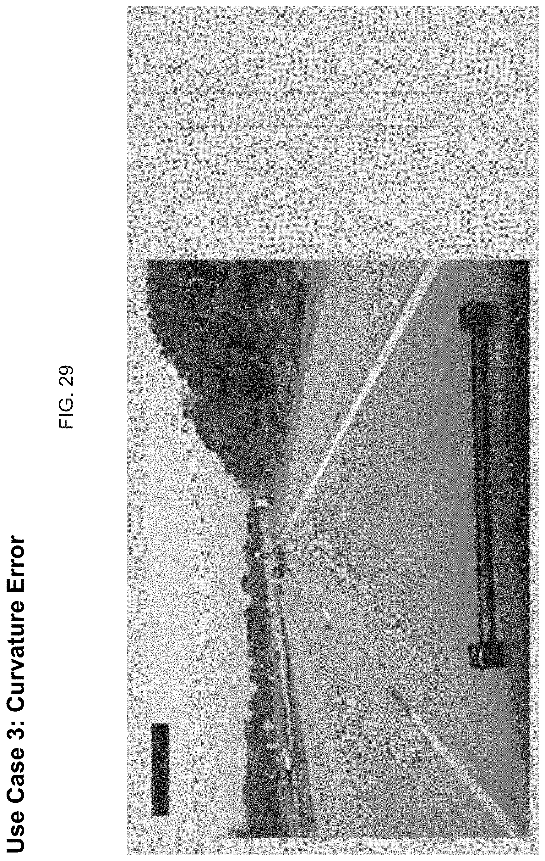
FIG. 4 is an image showing a use case where the camera may erroneously determine lane curvature;
FIG. 5 is an image showing a use case where the camera may track the wrong lane markers, such as by tracking an exit lane instead of the correct road lane markers;
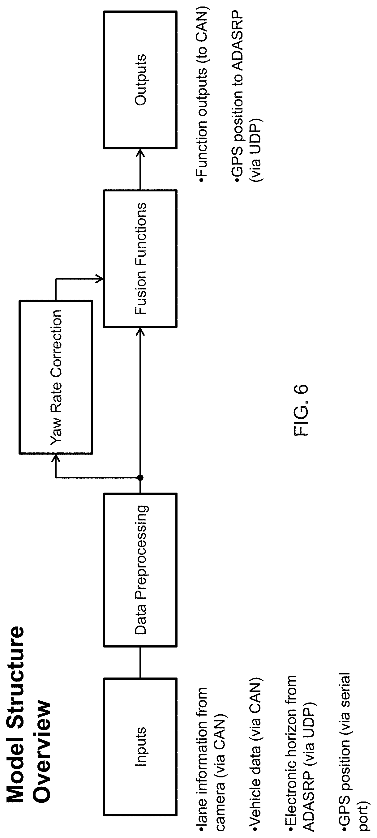
FIG. 6 is a block diagram of the system structure overview of the present invention;
FIG. 7 is a schematic showing the data preprocessing of the system of the present invention;
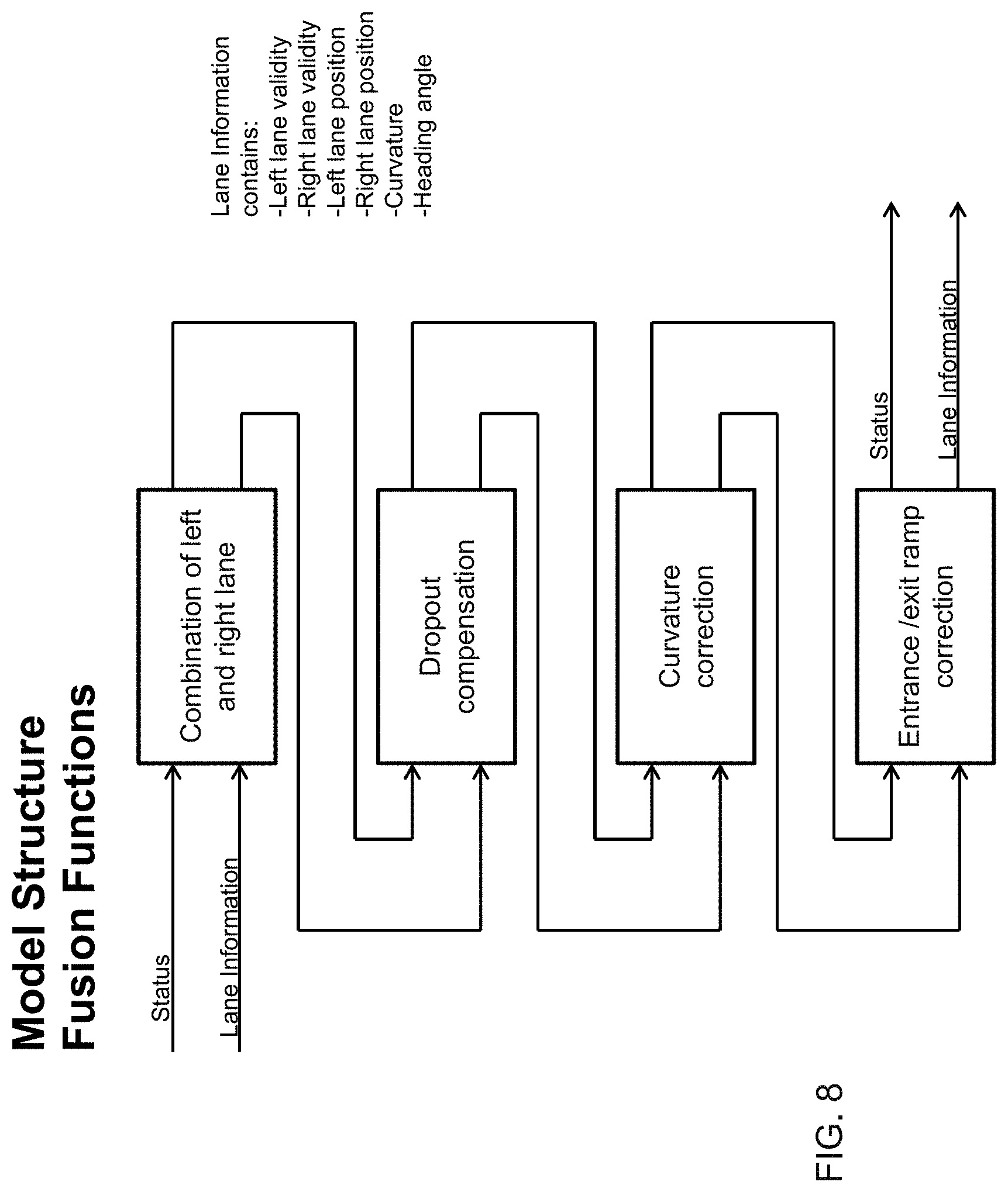
FIG. 8 is a schematic showing the fusion functions of the system of the present invention;
FIG. 9 is a schematic showing the process for determining the left lane and the right lane in accordance with the present invention;
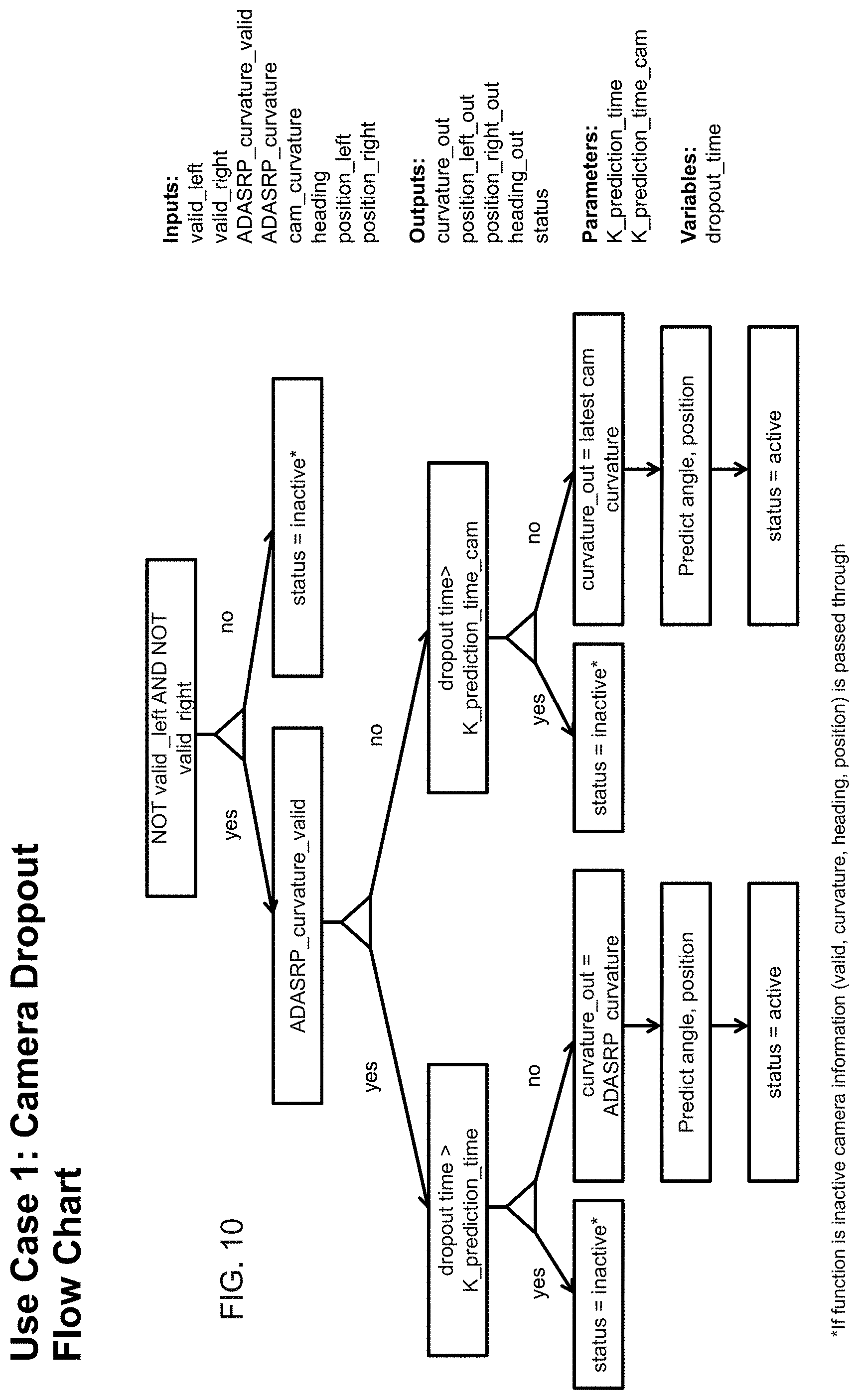
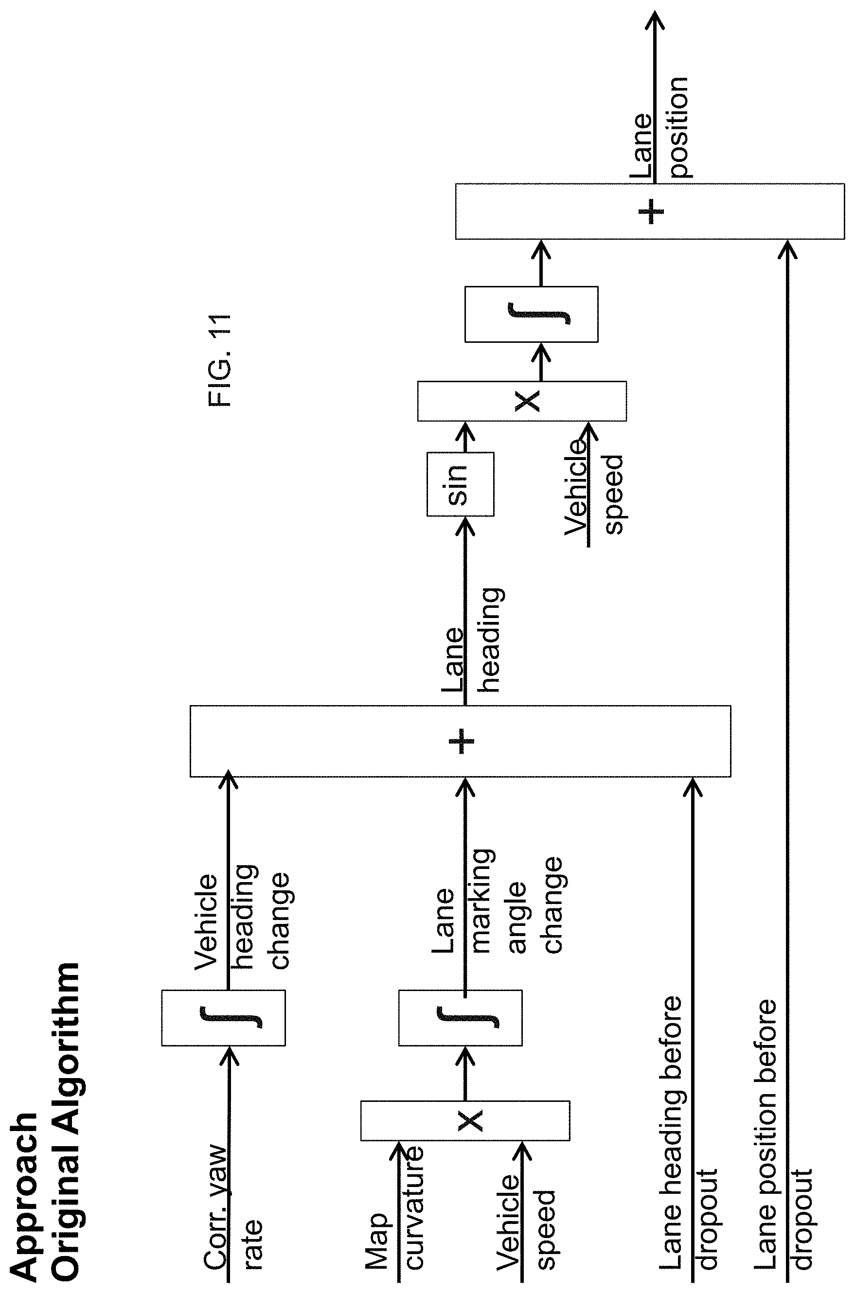
FIGS. 10-15 show application of the present invention to the first use case of FIG. 2;
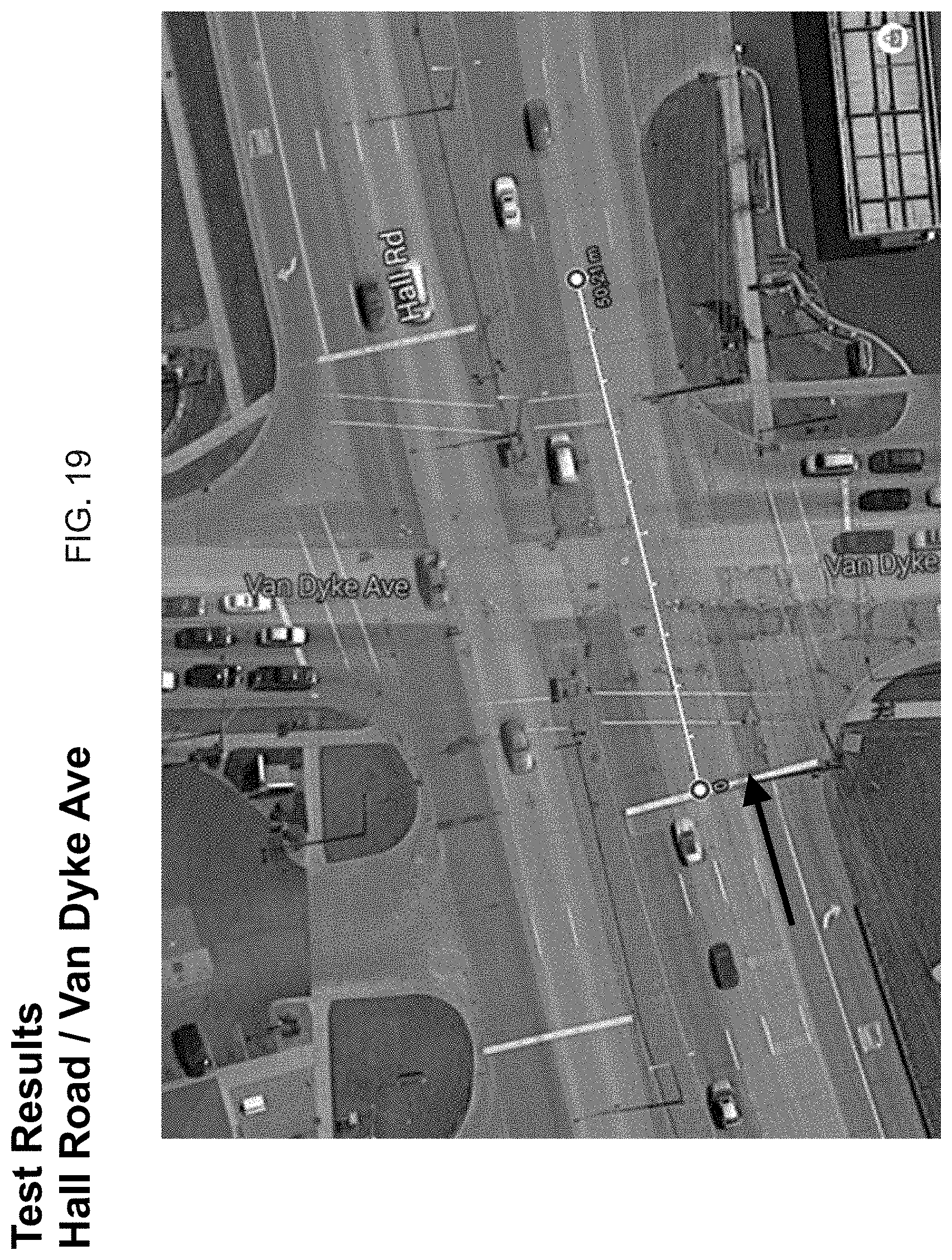
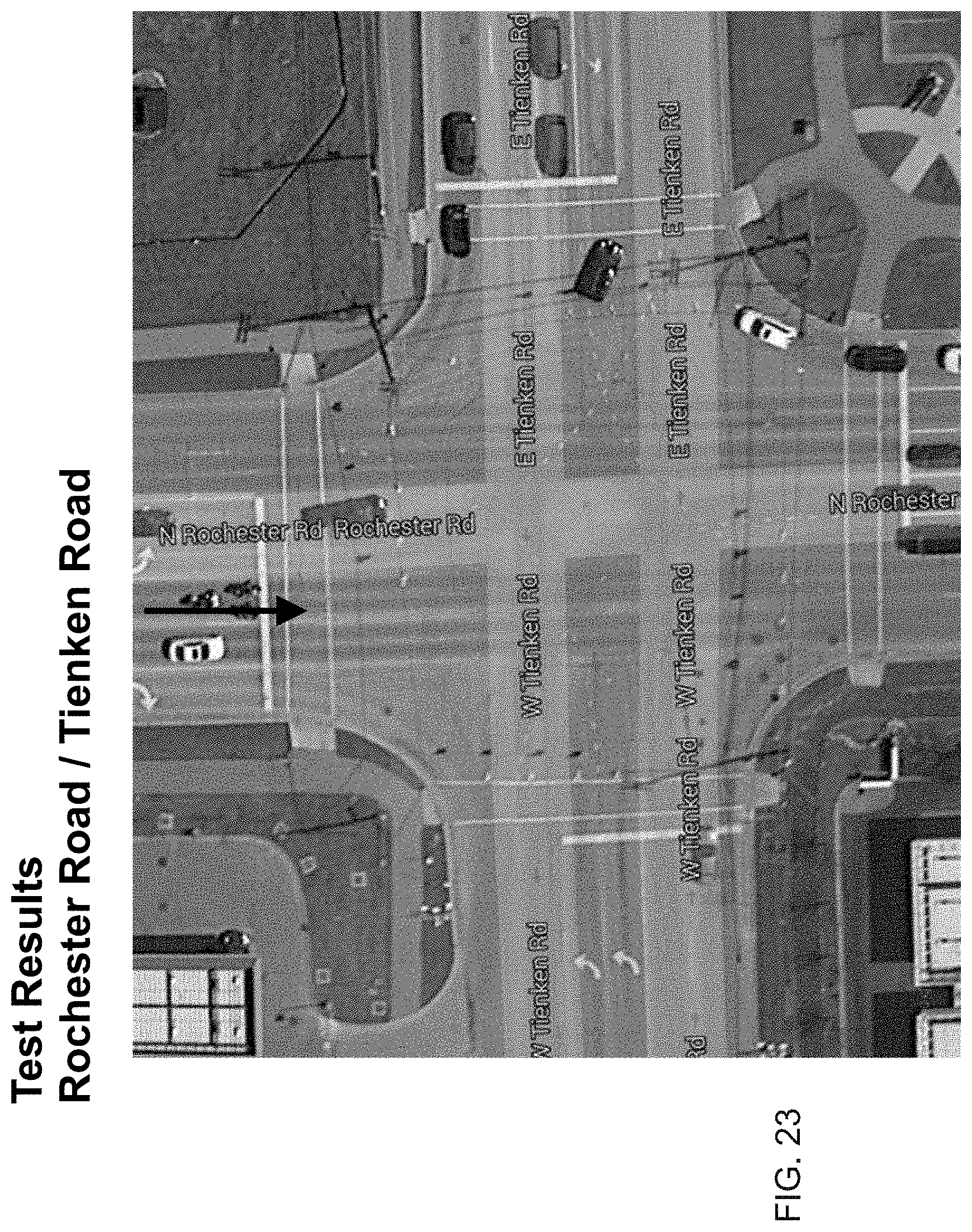
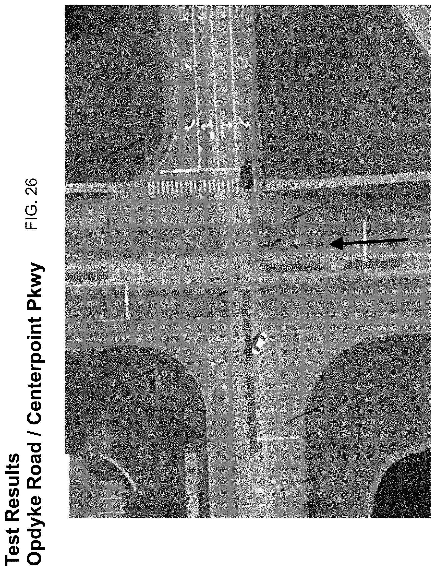
FIGS. 16-26 show application of the present invention to the second use case of FIG. 3;
FIGS. 27-29 show application of the present invention to the third use case of FIG. 4; and
FIGS. 30-32 show application of the present invention to the fourth use case of FIG. 5.
DESCRIPTION OF THE PREFERRED EMBODIMENTS
A vehicle vision system and/or driver assist system and/or object detection system and/or alert system operates to capture images exterior of the vehicle and may process the captured image data to display images and to detect objects at or near the vehicle and in the predicted path of the vehicle, such as to assist a driver of the vehicle in maneuvering the vehicle in a rearward direction. The vision system includes an image processor or image processing system that is operable to receive image data from one or more cameras and provide an output to a display device for displaying images representative of the captured image data. Optionally, the vision system may provide display, such as a rearview display or a top down or bird's eye or surround view display or the like.
Referring now to the drawings and the illustrative embodiments depicted therein, a vehicle 10 includes an imaging system or vision system 12 that includes at least one exterior facing imaging sensor or camera, such as a forward facing imaging sensor or camera 14a at a front portion of the vehicle or at and behind the windshield of the vehicle and viewing through the windshield, which captures images exterior and forward of the vehicle, with the camera having a lens for focusing images at or onto an imaging array or imaging plane or imager of the camera (FIG. 1). Optionally, the system may include multiple exterior facing imaging sensors or cameras, such as a rearwardly facing camera 14b at the rear of the vehicle, and a sidewardly/rearwardly facing camera 14c, 14d at respective sides of the vehicle, which capture images exterior of the vehicle. The forward viewing camera may be disposed at the windshield of the vehicle and view through the windshield and forward of the vehicle, such as for a machine vision system (such as for traffic sign recognition, headlamp control, pedestrian detection, collision avoidance, lane marker detection and/or the like). The vision system 12 includes a control or electronic control unit (ECU) or processor 18 that is operable to process image data captured by the camera or cameras and may detect objects or the like and/or provide displayed images at a display device 16 for viewing by the driver of the vehicle (although shown in FIG. 1 as being part of or incorporated in or at an interior rearview mirror assembly 20 of the vehicle, the control and/or the display device may be disposed elsewhere at or in the vehicle). The data transfer or signal communication from the camera to the ECU may comprise any suitable data or communication link, such as a vehicle network bus or the like of the equipped vehicle.
Lane information determined from image data captured by a forward viewing camera is erroneous in some situations. The camera information can be corrected by using an independent data source. By means of fusion of lane information from the camera and from a digital map, the quality of lane information can be improved. This function can be utilized by multiple ADAS features, such as, for example, Automated Driving and/or the like.
The present invention provides enhanced lane tracking in situations where the lane markers may not be present or where the lane markers are not readily detectable by processing of captured image data (such as when the view of the lane markings by the camera is obstructed, such as due to another vehicle or object on the road or due to a curvature in the road or undulation in the road or the like). The system of the present invention defines use cases and collects test data, such as video clips and CAN recording of camera outputs, vehicle chassis CAN, GPS position and the like. The system checks test data for use cases and develops functions to improve path reckoning performance in defined use cases where lane marking detection becomes unreliable, such as by replaying recorded CAN data in simulation. Thus, when the system determines that the vehicle is currently in one of the defined use cases, the system may adjust the path estimation process to adapt to the current condition or situation, thus providing enhanced path estimation in various conditions or types of situations that are typically encountered by a vehicle on the road. Testing has shown that the system functions in simulation and in test drives in Germany and USA.
Some exemplary use cases are shown in FIGS. 2-5 and include cases where the camera loses the lane markings for a few seconds (FIG. 2), where the camera loses lane markings at intersections (FIG. 3), where the system erroneously estimates the lane curvature (FIG. 4), and where the camera tracks an exit lane instead of the correct lane marking (FIG. 5).
The system structure overview is shown in FIG. 6, and the data preprocessing of the system is shown in FIG. 7. In the data preprocessing, a map database (such as ADASRP or the like) provides electronic horizon for configurable preview distance (such as, for example, about one kilometer or thereabouts). For this preview distance, attribute values (such as, for example, the radius of the road ahead of the subject vehicle) are provided along with the distance to the current subject vehicle position. The distance values are updated at 1 Hz rate, and additional attribute values are transmitted when the preview distance falls below a desired value. The fusion functions of the system are shown in FIG. 8, and the process for determining the left lane and the right lane is shown in FIG. 9.
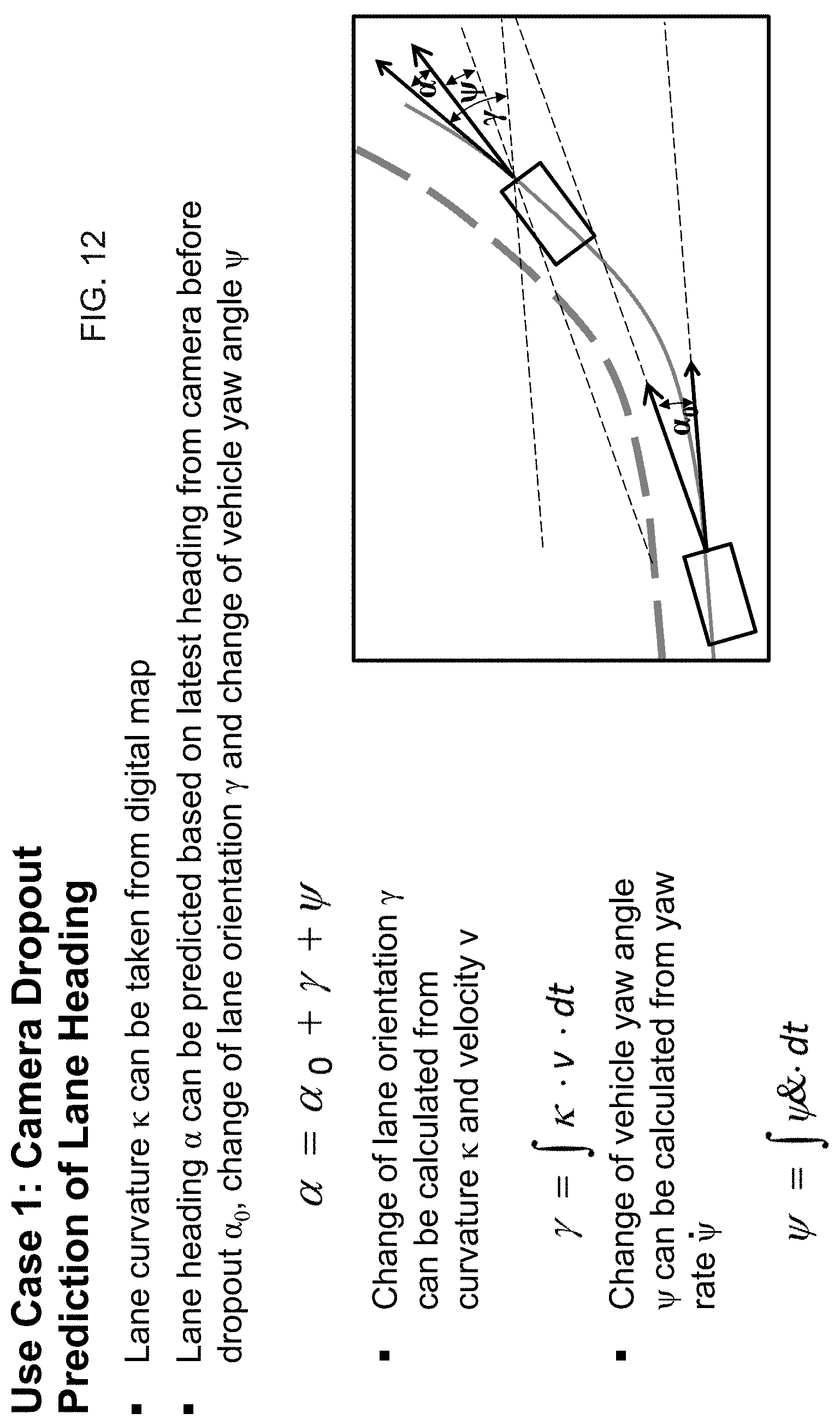
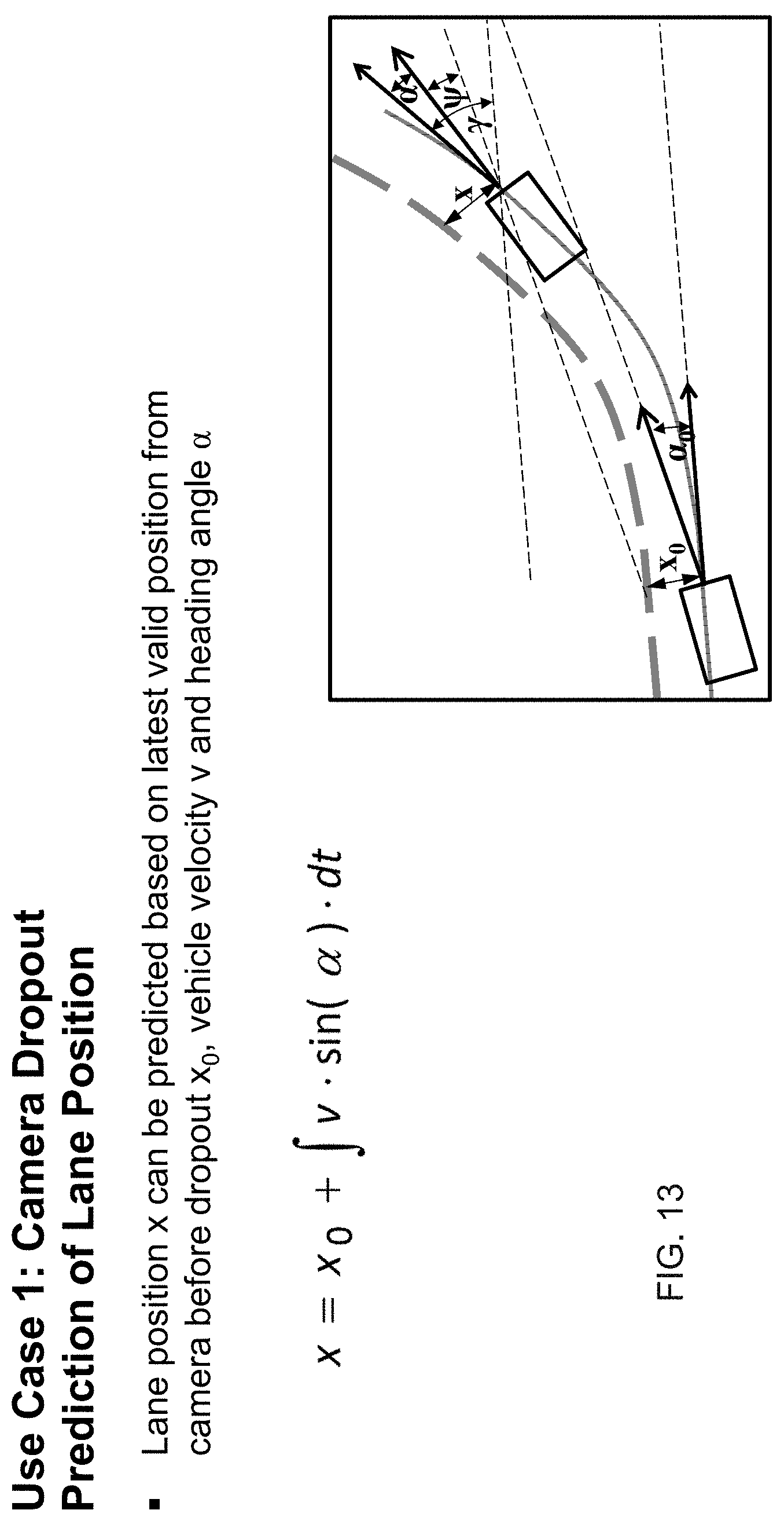
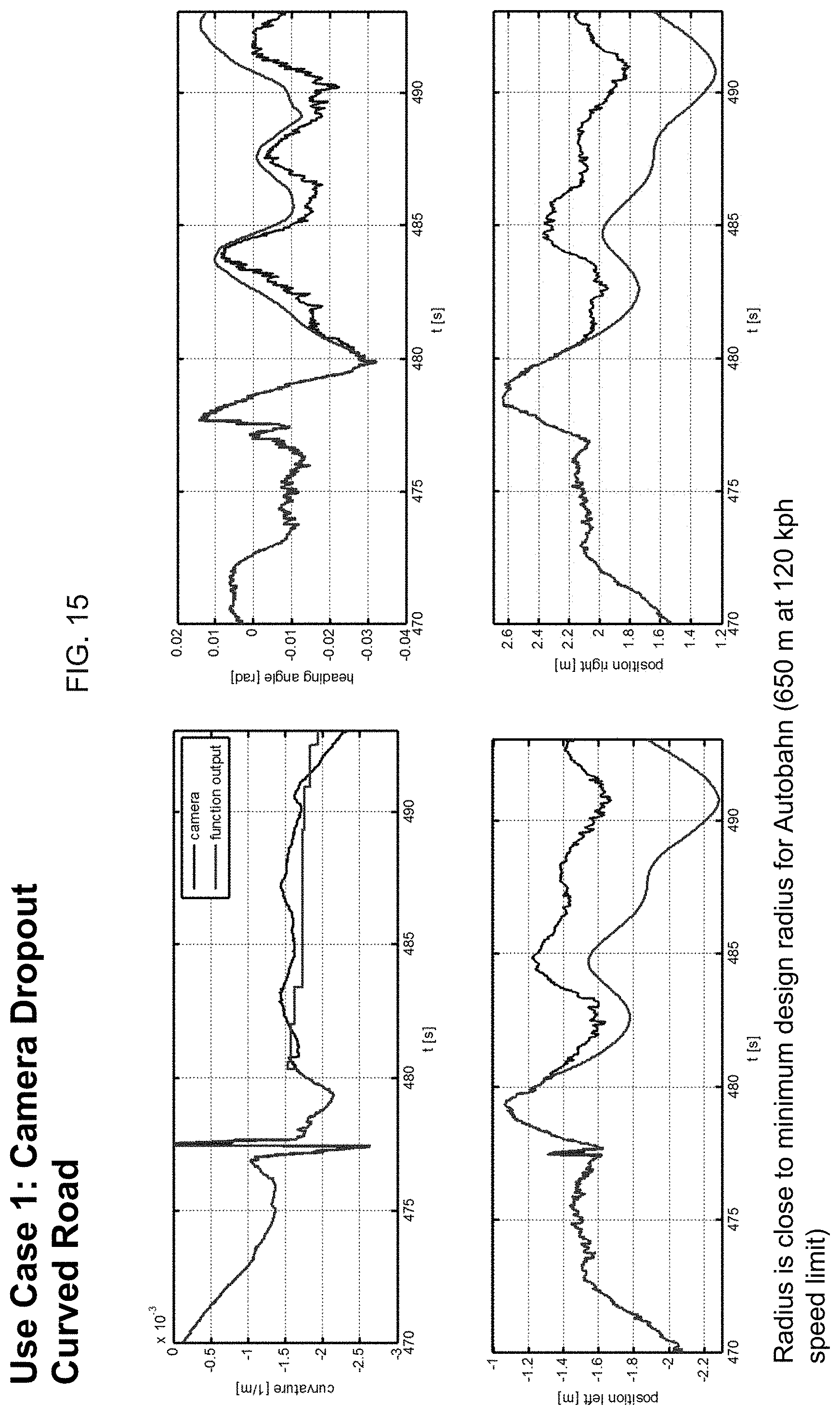
FIGS. 10-15 show application of the present invention to the first use case (FIG. 2), where the camera loses the lane markings for a few seconds. When such loss of lane markings occurs, the system predicts the lane heading responsive to a digital map, the latest heading from the camera before the loss, with changes calculated such as shown in FIGS. 12 and 13.
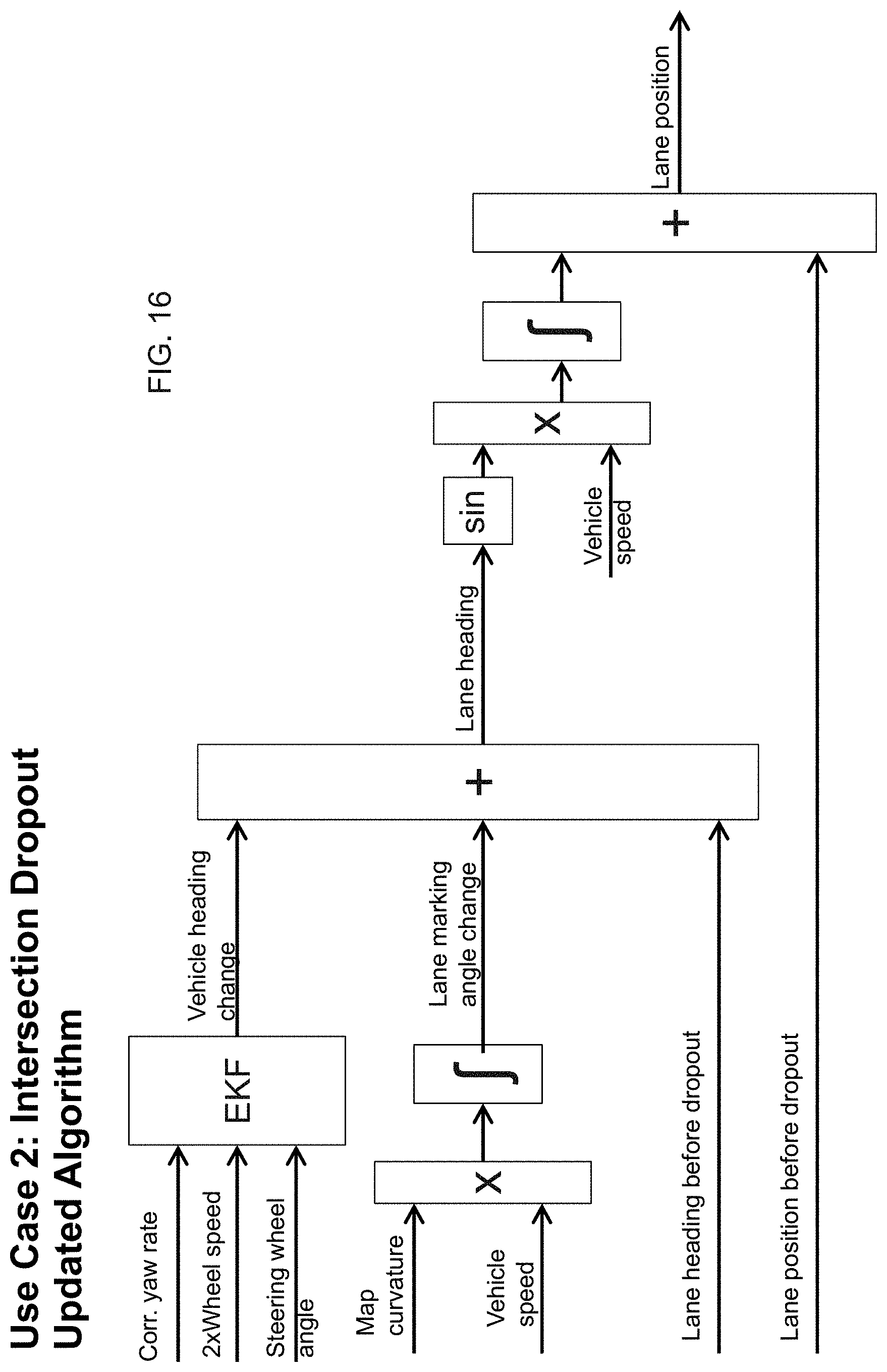
FIGS. 16-26 show application of the present invention to the second use case (FIG. 3), where the camera loses the lane markings at intersections. An enhanced dropout compensation algorithm has been developed based on use case 1 in order to compensate dropouts at intersections. The system and algorithm provide more accurate heading angle by using additional sensor data which are fused such as by means of an Extended Kalman Filter (EKF). The algorithm and heading angle estimation calculations are shown in FIGS. 16-18, and the results of test and parameterize algorithms in intersection scenarios are shown in FIGS. 19-26.
FIGS. 27-29 show application of the present invention to the third use case (FIG. 4), where the system erroneously estimates the lane curvature. The algorithm (see FIG. 27) determines whether or not to use the determined left and/or right curvatures to estimate the path of travel for the vehicle to maintain the vehicle in the lane it was traveling along.
FIGS. 30-32 show application of the present invention to the fourth use case (FIG. 5), where the camera tracks an exit lane instead of the correct lane marking. The algorithm (see FIG. 30) uses map data to determine distances (from the vehicle's current geographical location) to intersections or road crossings and determines whether or not a determined lane marking may be an exit lane marking to estimate the path of travel for the vehicle to maintain the vehicle in the lane it was traveling along.
Thus, the present invention provides enhanced tracking or estimation of lanes of the road on which the vehicle is traveling for situations where the camera or system loses the lane markings or may track the wrong lane markings. The system provides compensation of camera errors and increases the availability of automated driving functions (such as, for example, lane keeping or the like). The compensation of camera errors requires a map data base that has to be available in the vehicle. The algorithms to compensate for camera dropouts are not complex and thus the system of the present invention does not require high processing power. The system may utilize camera and navigation fusion functions, which may be implemented in the camera ECU or at a control unit of the vehicle that is separate from the camera (and that may communicate with the camera via a communication bus of the vehicle). The system may utilize a sensor CAN bus and a vehicle CAN bus, and may use inputs such as vehicle velocity and yaw rate and position and heading information and the like, along with GPS information pertaining to the vehicle location and the road along which the vehicle is traveling.
Therefore, the present invention provides a system that resolves some issues with lane data received from the image processing system, where there are situations like cresting a hill, crossing an intersection, passing entrance/exit ramps, or just unique situations where vehicles line up oddly with the lane markings and the image processing system may report bad data. For lane keeping (nudging at the marking) and particularly for lane centering (always active), it is important to have a good model of the path ahead. The system of the present invention thus creates an abstraction layer between the image processing and the feature that would use the path (such as automated driving or adaptive cruise control or the like). With the system of the present invention, the lane data from the image processing becomes one of the inputs to the new abstraction layer, rather than the sole supplier of path information. That input is combined with map data, GPS positioning data or information, differential wheel speeds, and/or the like, to determine where the desired path is ahead of the vehicle (even when lane markings are not present or are difficult to discern via image processing of captured image data). The vehicle is allowed to maneuver about this predicted or estimated path of travel and the path will update independently of the vehicle "virtually under the vehicle," even when no lane marking data is present ahead of the vehicle or discernible by the camera and image processing.
The present invention provides an abstraction layer that has the image processing lane output as one of the inputs. It also takes inputs from map data, GPS positioning, yaw rate, steering angle and differential wheel speeds (preferably non-driven wheels, but even 4wd vehicles can be taken into consideration). The system may determine objects on the road plane that obstruct the path. All of this is fused together to make a path reckoning system. The output of such a system provides an enhanced model of the path ahead of the subject vehicle. The system of the present invention is not a typical dead reckoning system that tries to maintain the vehicle's trajectory when the sensor data drops out. Instead, the present invention creates a path for the vehicle using multiple inputs that may drop out. The vehicle can move about on this path and the control system will still react to the path boundaries, even if there are no lane markings. Testing has found the system to be accurate to within about 10 cm of the actual lane markings after traveling as much as 100 meters. As shown in the drawings, FIGS. 20 and 22, bottom left graph, the lane data drop out is bounded between the vertical bars (at around 40 and 43 in FIG. 20 and at around 63.6 and 69.4 in FIG. 22). As the vehicle approaches the far side the lane markings come back and the error is about 0.1 m (which is about the width of a lane marking).
The camera or sensor may comprise any suitable camera or sensor. Optionally, the camera may comprise a "smart camera" that includes the imaging sensor array and associated circuitry and image processing circuitry and electrical connectors and the like as part of a camera module, such as by utilizing aspects of the vision systems described in International Publication Nos. WO 2013/081984 and/or WO 2013/081985, which are hereby incorporated herein by reference in their entireties.
The system includes an image processor operable to process image data captured by the camera or cameras, such as for detecting objects or other vehicles or pedestrians or the like in the field of view of one or more of the cameras. For example, the image processor may comprise an image processing chip such as a chip of the EyeQ family of image processing chips available from Mobileye Vision Technologies Ltd. of Jerusalem, Israel, and may include object detection software (such as the types described in U.S. Pat. Nos. 7,855,755; 7,720,580 and/or 7,038,577, which are hereby incorporated herein by reference in their entireties), and may analyze image data to detect vehicles and/or other objects. Responsive to such image processing, and when an object or other vehicle is detected, the system may generate an alert to the driver of the vehicle and/or may generate an overlay at the displayed image to highlight or enhance display of the detected object or vehicle, in order to enhance the driver's awareness of the detected object or vehicle or hazardous condition during a driving maneuver of the equipped vehicle.
The vehicle may include any type of sensor or sensors, such as imaging sensors or radar sensors or lidar sensors or ladar sensors or ultrasonic sensors or the like. The system may also communicate with other systems, such as via a vehicle-to-vehicle communication system or a vehicle-to-infrastructure communication system or the like. Such car2car or vehicle to vehicle (V2V) and vehicle-to-infrastructure (car2X or V2X or V2I or 4G or 5G) technology provides for communication between vehicles and/or infrastructure based on information provided by one or more vehicles and/or information provided by a remote server or the like. Such vehicle communication systems may utilize aspects of the systems described in U.S. Pat. Nos. 6,690,268; 6,693,517 and/or 7,580,795, and/or U.S. Publication Nos. US-2014-0375476; US-2014-0218529; US-2013-0222592; US-2012-0218412; US-2012-0062743; US-2015-0251599; US-2015-0158499; US-2015-0124096; US-2015-0352953; US-2016-0036917 and/or US-2016-0210853, which are hereby incorporated herein by reference in their entireties.
The imaging sensor or camera may capture image data for image processing and may comprise any suitable camera or sensing device, such as, for example, a two dimensional array of a plurality of photosensor elements arranged in at least 640 columns and 480 rows (at least a 640.times.480 imaging array, such as a megapixel imaging array or the like), with a respective lens focusing images onto respective portions of the array. The photosensor array may comprise a plurality of photosensor elements arranged in a photosensor array having rows and columns. Preferably, the imaging array has at least 300,000 photosensor elements or pixels, more preferably at least 500,000 photosensor elements or pixels and more preferably at least 1 million photosensor elements or pixels. The imaging array may capture color image data, such as via spectral filtering at the array, such as via an RGB (red, green and blue) filter or via a red/red complement filter or such as via an RCC (red, clear, clear) filter or the like. The logic and control circuit of the imaging sensor may function in any known manner, and the image processing and algorithmic processing may comprise any suitable means for processing the images and/or image data.
For example, the vision system and/or processing and/or camera and/or circuitry may utilize aspects described in U.S. Pat. Nos. 9,233,641; 9,146,898; 9,174,574; 9,090,234; 9,077,098; 8,818,042; 8,886,401; 9,077,962; 9,068,390; 9,140,789; 9,092,986; 9,205,776; 8,917,169; 8,694,224; 7,005,974; 5,760,962; 5,877,897; 5,796,094; 5,949,331; 6,222,447; 6,302,545; 6,396,397; 6,498,620; 6,523,964; 6,611,202; 6,201,642; 6,690,268; 6,717,610; 6,757,109; 6,802,617; 6,806,452; 6,822,563; 6,891,563; 6,946,978; 7,859,565; 5,550,677; 5,670,935; 6,636,258; 7,145,519; 7,161,616; 7,230,640; 7,248,283; 7,295,229; 7,301,466; 7,592,928; 7,881,496; 7,720,580; 7,038,577; 6,882,287; 5,929,786 and/or 5,786,772, and/or U.S. Publication Nos. 2014/0340510; 2014/0313339; 2014/0347486; 2014/0320658; 2014/0336876; 2014/0307095; 2014/0327774; 2014/0327772; 2014/0320636; 2014/0293057; 2014/0309884; 2014/0226012; 2014/0293042; 2014/0218535; 2014/0218535; 2014/0247354; 2014/0247355; 2014/0247352; 2014/0232869; 2014/0218529; 2014/0211009; 2014/0160276; 2014/0168437; 2014/0168415; 2014/0160291; 2014/0152825; 2014/0139676; 2014/0138140; 2014/0104426; 2014/0098229; 2014/0085472; 2014/0067206; 2014/0049646; 2014/0052340; 2014/0025240; 2014/0028852; 2014/005907; 2013/0314503; 2013/0298866; 2013/0222593; 2013/0300869; 2013/0278769; 2013/0258077; 2013/0258077; 2013/0242099; 2013/0222592; 2013/0215271; 2013/0141578 and/or 2013/0002873, which are all hereby incorporated herein by reference in their entireties.
Optionally, the vision system may include a display for displaying images captured by one or more of the imaging sensors for viewing by the driver of the vehicle while the driver is normally operating the vehicle. Optionally, for example, the vision system may include a video display device, such as by utilizing aspects of the video display systems described in U.S. Pat. Nos. 5,530,240; 6,329,925; 7,855,755; 7,626,749; 7,581,859; 7,446,650; 7,338,177; 7,274,501; 7,255,451; 7,195,381; 7,184,190; 5,668,663; 5,724,187; 6,690,268; 7,370,983; 7,329,013; 7,308,341; 7,289,037; 7,249,860; 7,004,593; 4,546,551; 5,699,044; 4,953,305; 5,576,687; 5,632,092; 5,677,851; 5,708,410; 5,737,226; 5,802,727; 5,878,370; 6,087,953; 6,173,508; 6,222,460; 6,513,252 and/or 6,642,851, and/or U.S. Publication Nos. US-2012-0162427; US-2006-0050018 and/or US-2006-0061008, which are all hereby incorporated herein by reference in their entireties. Optionally, the vision system (utilizing the forward facing camera and a rearward facing camera and other cameras disposed at the vehicle with exterior fields of view) may be part of or may provide a display of a top-down view or birds-eye view system of the vehicle or a surround view at the vehicle, such as by utilizing aspects of the vision systems described in International Publication Nos. WO 2010/099416; WO 2011/028686; WO 2012/075250; WO 2013/019795; WO 2012/075250; WO 2012/145822; WO 2013/081985; WO 2013/086249 and/or WO 2013/109869, and/or U.S. Publication No. US-2012-0162427, which are hereby incorporated herein by reference in their entireties.
Changes and modifications in the specifically described embodiments can be carried out without departing from the principles of the invention, which is intended to be limited only by the scope of the appended claims, as interpreted according to the principles of patent law including the doctrine of equivalents.
* * * * *
D00000
D00001
D00002
D00003
D00004
D00005
D00006
D00007
D00008
D00009
D00010
D00011
D00012
D00013
D00014

D00015
D00016
D00017

D00018

D00019
D00020

D00021

D00022

D00023
D00024

D00025

D00026
D00027

D00028

D00029
D00030

D00031

D00032

XML
uspto.report is an independent third-party trademark research tool that is not affiliated, endorsed, or sponsored by the United States Patent and Trademark Office (USPTO) or any other governmental organization. The information provided by uspto.report is based on publicly available data at the time of writing and is intended for informational purposes only.
While we strive to provide accurate and up-to-date information, we do not guarantee the accuracy, completeness, reliability, or suitability of the information displayed on this site. The use of this site is at your own risk. Any reliance you place on such information is therefore strictly at your own risk.
All official trademark data, including owner information, should be verified by visiting the official USPTO website at www.uspto.gov. This site is not intended to replace professional legal advice and should not be used as a substitute for consulting with a legal professional who is knowledgeable about trademark law.