Method of producing hydrogen peroxide using nanostructured bismuth oxide
Shaddad , et al.
U.S. patent number 10,683,577 [Application Number 16/592,713] was granted by the patent office on 2020-06-16 for method of producing hydrogen peroxide using nanostructured bismuth oxide. This patent grant is currently assigned to King Saud University. The grantee listed for this patent is KING SAUD UNIVERSITY. Invention is credited to Abdullah M. Almayouf, Prabhakarn Arunachalam, Maged N. Shaddad.


| United States Patent | 10,683,577 |
| Shaddad , et al. | June 16, 2020 |
Method of producing hydrogen peroxide using nanostructured bismuth oxide
Abstract
The method of producing hydrogen peroxide using nanostructured bismuth oxide is an electrochemical process for producing hydrogen peroxide using a cathode formed as oxygen-deficient nanostructured bismuth oxide deposited as a film on the surface of a conducting substrate. An anode and the cathode are immersed in an alkaline solution saturated with oxygen in an electrolytic cell. An electrical potential is established across the cathode and the anode to initiate electrochemical reduction of the oxygen in the alkaline solution to produce hydrogen peroxide by oxygen reduction reaction.
| Inventors: | Shaddad; Maged N. (Riyadh, SA), Arunachalam; Prabhakarn (Riyadh, SA), Almayouf; Abdullah M. (Riyadh, SA) | ||||||||||
|---|---|---|---|---|---|---|---|---|---|---|---|
| Applicant: |
|
||||||||||
| Assignee: | King Saud University (Riyadh,
SA) |
||||||||||
| Family ID: | 71075214 | ||||||||||
| Appl. No.: | 16/592,713 | ||||||||||
| Filed: | October 3, 2019 |
| Current U.S. Class: | 1/1 |
| Current CPC Class: | C25B 11/0415 (20130101); C25B 11/0452 (20130101); C25B 1/30 (20130101); C25B 11/0405 (20130101); C25B 11/0426 (20130101) |
| Current International Class: | C25B 11/04 (20060101); C25B 1/30 (20060101) |
References Cited [Referenced By]
U.S. Patent Documents
| 7011908 | March 2006 | Atwater |
| 105951117 | Sep 2016 | CN | |||
| 105970247 | Sep 2016 | CN | |||
| 106086922 | Nov 2016 | CN | |||
| H0733410 | Feb 1995 | JP | |||
Other References
|
Shinnanoe et al, "Bismuth Oxide Thin Film as New Electrochromic Material," Solid State Ionics, 1998, 113-115 415-419. cited by examiner . Liu et al., "Engineering Bi2O3-Bi2S3 heterostructure for superior lithium storage," Scientific Reports, vol. 5, Article No. 9307, Mar. 23, 2015. cited by applicant. |
Primary Examiner: Jain; Salil
Attorney, Agent or Firm: Litman; Richard C. Nath, Goldberg & Meyer
Claims
We claim:
1. A method of making an electrode for electrochemical production of hydrogen peroxide, comprising the steps of: electrodepositing a film of bismuth on a substrate, the substrate having a surface; annealing the film of bismuth in air, thereby oxidizing the bismuth to form a film of bismuth oxide (Bi.sub.2O.sub.3) on the surface of the substrate; and annealing the film of bismuth oxide under vacuum, thereby reducing the bismuth oxide to form a film of oxygen-deficient bismuth oxide of formula Bi.sub.2O.sub.3-x on the surface of the substrate, wherein x is greater than 0 and less than 3.
2. The method of making an electrode according to claim 1, wherein said substrate comprises fluorine-doped tin oxide.
3. The method of making an electrode according to claim 1, wherein said step of annealing the film of bismuth in air comprises heating the bismuth film deposited on the substrate at 450.degree. C. in air.
4. The method of making an electrode according to claim 3, wherein said step of annealing the film of bismuth in air comprises heating the bismuth film deposited on the substrate at 450.degree. C. in air for two hours.
5. The method of making an electrode according to claim 1, wherein said step of annealing the film of bismuth oxide under vacuum comprises heating the bismuth oxide film deposited on the substrate at 350.degree. C. under vacuum.
6. The method of making an electrode according to claim 4, wherein said step of annealing the film of bismuth oxide under vacuum comprises heating the bismuth oxide film deposited on the substrate at 350.degree. C. under vacuum for between 0.5 and 5 hours.
Description
BACKGROUND
1. Field
The disclosure of the present patent application relates to the production of hydrogen peroxide, and particularly to a method of producing hydrogen peroxide using nanostructured bismuth oxide by electrochemical reduction of oxygen using an electrode comprising a dendritic nanostructured bismuth oxide (Bi.sub.2O.sub.3-x).
2. Description of the Related Art
Hydrogen peroxide (H.sub.2O.sub.2) is an essential chemical feedstock for chemical industries, medicine and environmental remediation, as well as supplying an oxidant in renewable energy conversion applications and in storage devices. Due to its powerful oxidizing nature, H.sub.2O.sub.2 is also used in water treatment and as an energy carrier in many chemical processes without generating toxic by-products. At present, the industrial production of high-purity H.sub.2O.sub.2 solution typically relies on an anthraquinone method (i.e., the Riedl-Pfleiderer process), which involves the use of toxic solvents and requires high energy consumption. Transport, handling, and storage of concentrated H.sub.2O.sub.2 produced by the method raises further safety concerns. Therefore, an effective in situ H.sub.2O.sub.2 production technology is desirable.
H.sub.2O.sub.2 may be directly generated electrochemically by oxygen reduction reaction (ORR). ORR in aqueous solutions occurs primarily through two pathways, the direct 4-electron reduction pathway from O.sub.2 to H.sub.2O, and the 2-electron reduction pathway from O.sub.2 to hydrogen peroxide (H.sub.2O.sub.2). Non-precious metal electrocatalysts with high selectivity for the electrocatalytic reduction of O.sub.2 to H.sub.2O.sub.2 are desired for the establishment of green and sustainable chemistry. Bismuth oxide (Bi.sub.2O.sub.3) is a p-type semiconductor material with potential as an efficient ORR electrocatalyst due to its low conductivity and reactivity. The effect of oxygen vacancies induced in Bi.sub.2O.sub.3, i.e., Bi.sub.2O.sub.3-x, on electrochemical generation of H.sub.2O.sub.2 is not known or predicted.
Thus, a method of producing hydrogen peroxide using nanostructured bismuth oxide solving the aforementioned problems is desired.
SUMMARY
The method of producing hydrogen peroxide using nanostructured bismuth oxide as described herein is an electrochemical approach for producing hydrogen peroxide using a cathode formed as a nanostructured dendritic (ND) oxygen-deficient bismuth oxide (Bi.sub.2O.sub.3-x) electrode surface. Bi.sub.2O.sub.3-x dendritic nanostructures may be grown on a conducting substrate, for example, by first depositing a bismuth film on the substrate, annealing the bismuth film in air to convert the bismuth film to a film of bismuth oxide (Bi.sub.2O.sub.3), and then annealing the bismuth oxide film under vacuum to create oxygen vacancies (Bi.sub.2O.sub.3-x). The deposition step may be electrodeposition. The conducting substrate may be a transparent conducting substrate, such as fluorine-doped tin oxide (FTO). In use, an anode and the cathode prepared in this manner may be immersed in an alkaline medium saturated with oxygen in an electrochemical cell to produce hydrogen peroxide by oxygen reduction reaction.
These and other features of the present subject matter will become readily apparent upon further review of the following specification and drawings.
BRIEF DESCRIPTION OF THE DRAWINGS
FIG. 1A is a Field Emission Scanning Electron Microscopy (FESEM) micrograph top view of bismuth film electrodeposited on a fluorine-doped tin oxide (FTO) substrate as a first step in forming an electrode.
FIG. 1B is a FESEM micrograph side view of bismuth electrodeposited on an FTO substrate.
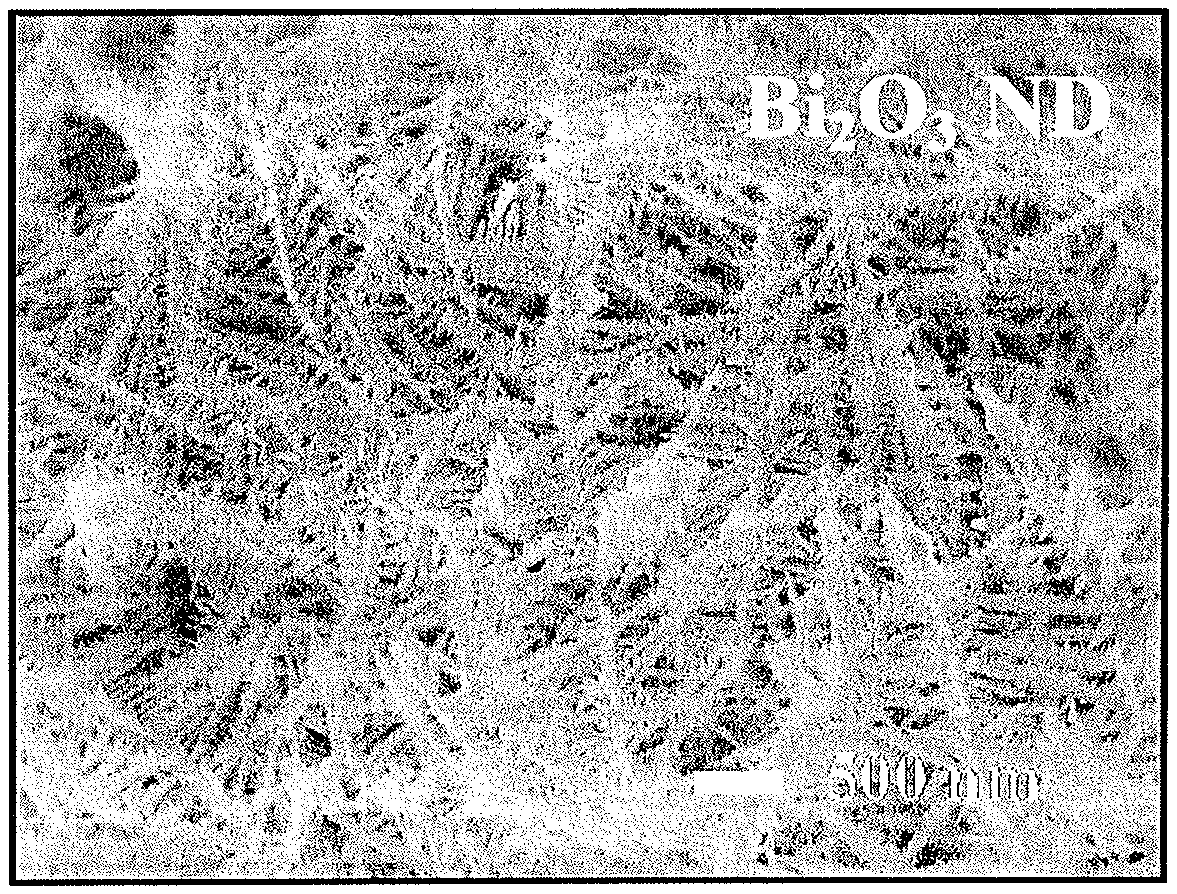
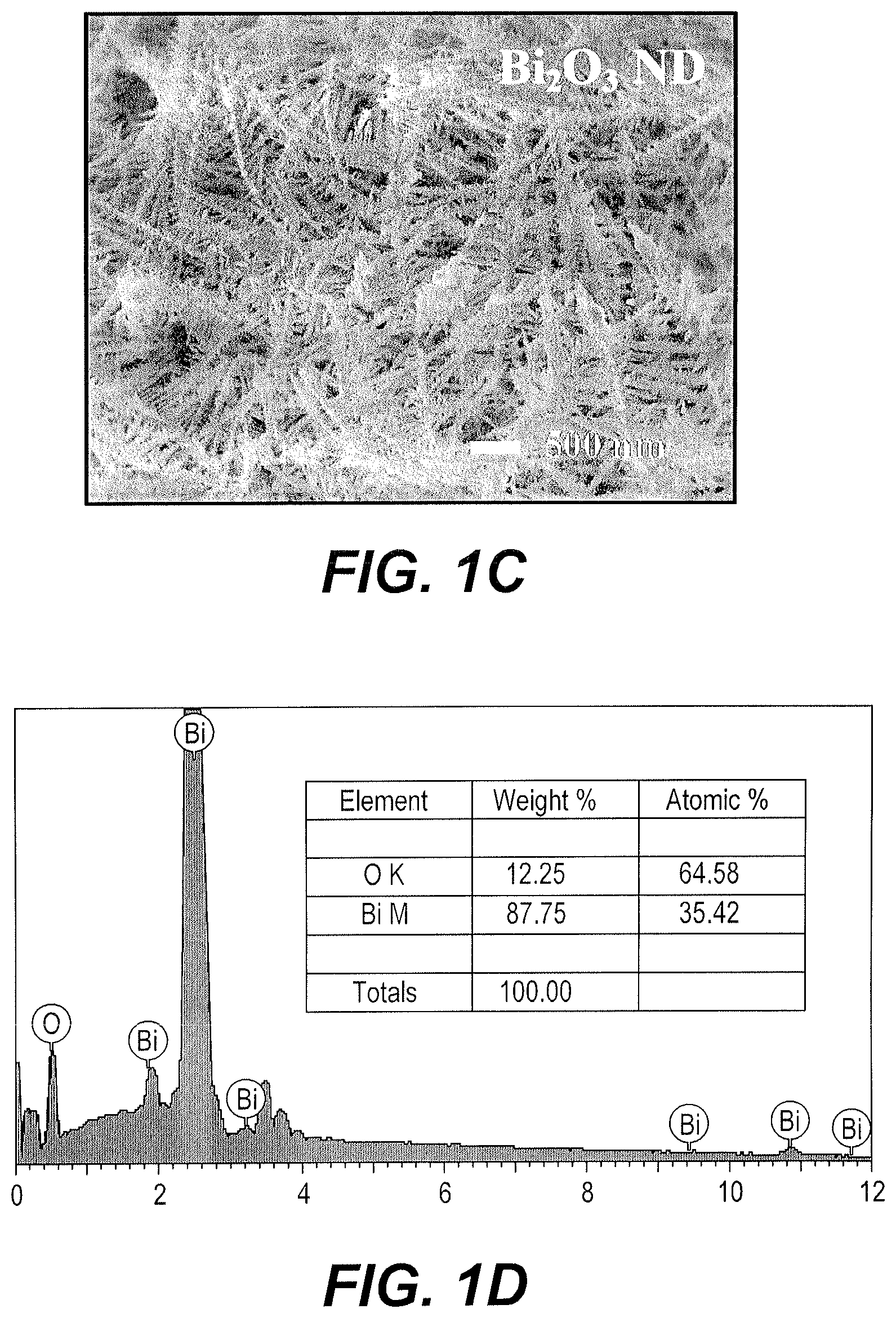
FIG. 1C is a FESEM micrograph of the electrode of FIG. 1A after annealing the electrode in air to convert the bismuth to Bi.sub.2O.sub.3.
FIG. 1D is an Energy Dispersive Spectrographic (EDS) spectrum of the Bi.sub.2O.sub.3 deposited on the electrode of FIG. 1C.
FIG. 1E is a FESEM micrograph of the electrode of FIG. 1C after subsequently annealing the electrode under vacuum to form an oxygen deficient Bi.sub.2O.sub.3-x/FTO electrode.
FIG. 1F is an EDS spectrum of the oxygen deficient Bi.sub.2O.sub.3-x deposited on the electrode of FIG. 1E.
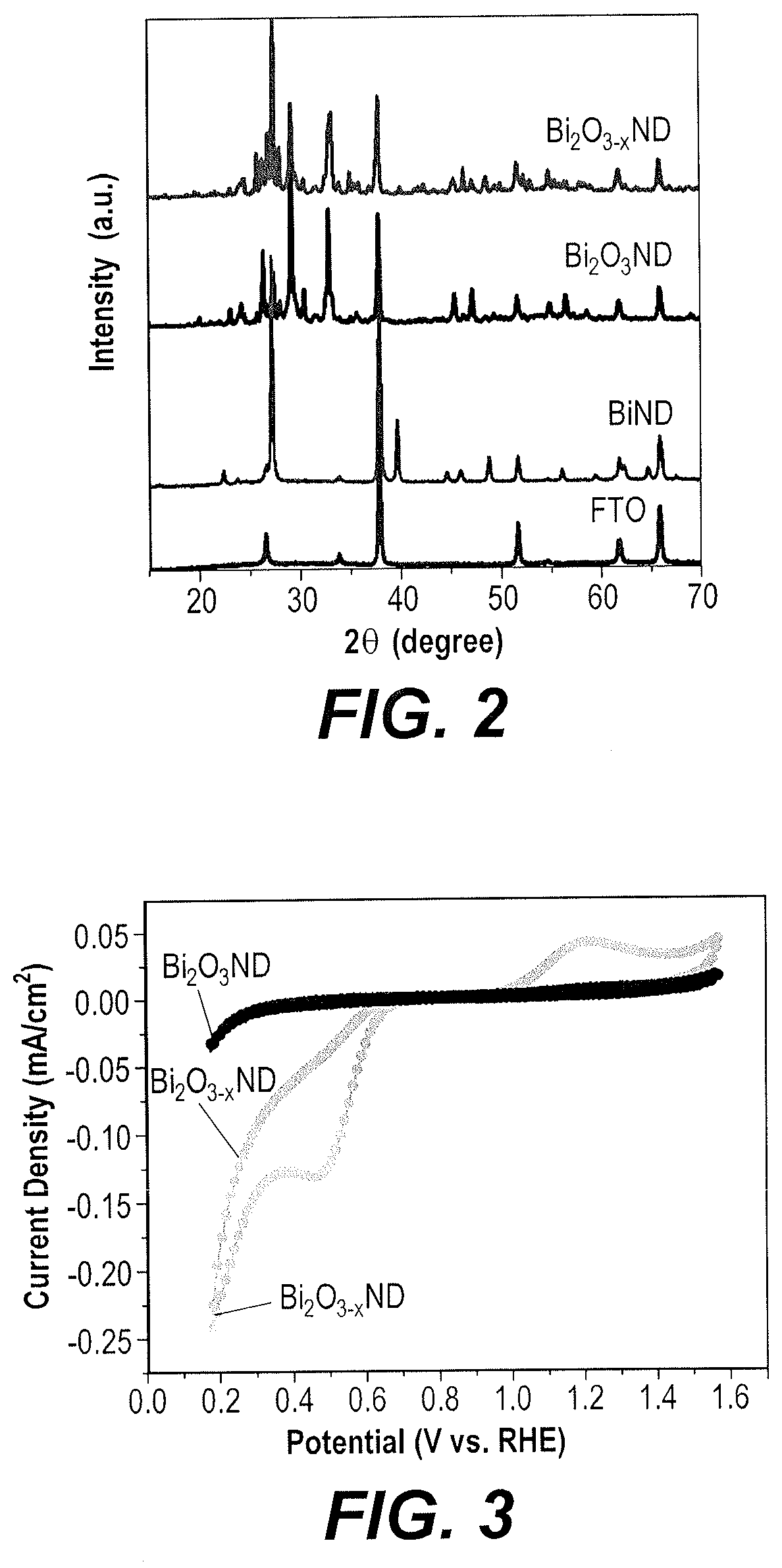
FIG. 2 is a composite X-ray powder diffraction (XRD) diffractogram comparing patterns for Bi nanostructured dendritic (ND) film, Bi.sub.2O.sub.3 ND and Bi.sub.2O.sub.3-x ND on FTO substrates.
FIG. 3 is a composite cyclic voltammetry (CV) voltammogram comparing traces of Bi.sub.2O.sub.3 ND/FTO electrodes (without being annealed under vacuum) with Bi.sub.2O.sub.3-x ND/FTO electrodes (rendered oxygen deficient by annealing under vacuum) in alkaline solution.
FIG. 4 is a composite linear sweep voltammetry (LSV) voltammogram comparing traces of Bi.sub.2O.sub.3 ND/FTO electrodes, Bi.sub.2O.sub.3-x ND/FTO electrodes, and Pt (20%)/C electrodes in alkaline solution.
FIG. 5A is a composite LSV voltammogram comparing traces taken with a Bi.sub.2O.sub.3 ND/FTO electrode in alkaline solution where the solution was purged for 20 min with either pure nitrogen (N.sub.2), air or pure oxygen (O.sub.2).
FIG. 5B is a composite LSV voltammogram comparing traces taken with a Bi.sub.2O.sub.3-xND/FTO electrode in alkaline solution where the solution was purged for 20 min with either pure nitrogen (N.sub.2), air, or pure oxygen (O.sub.2).
FIG. 5C is a composite LSV voltammogram comparing a trace taken with a Bi.sub.2O.sub.3 ND/FTO electrode in alkaline solution saturated with oxygen to a trace taken with a Bi.sub.2O.sub.3-x ND/FTO electrode in alkaline solution saturated with oxygen.
FIG. 6A is a composite CV voltammogram taken in alkaline solution comparing a CV trace of a Bi.sub.2O.sub.3 ND/FTO electrode before addition of H.sub.2O.sub.2 with a CV trace of a Bi.sub.2O.sub.3 ND/FTO electrode after addition of 0.4M H.sub.2O.sub.2 (30%).
FIG. 6B is a composite CV voltammogram taken in alkaline solution comparing a CV trace of a Bi.sub.2O.sub.3-x ND/FTO electrode before addition of H.sub.2O.sub.2 with a CV trace of a Bi.sub.2O.sub.3-xND/FTO electrode after addition of 0.4M H.sub.2O.sub.2 (30%).
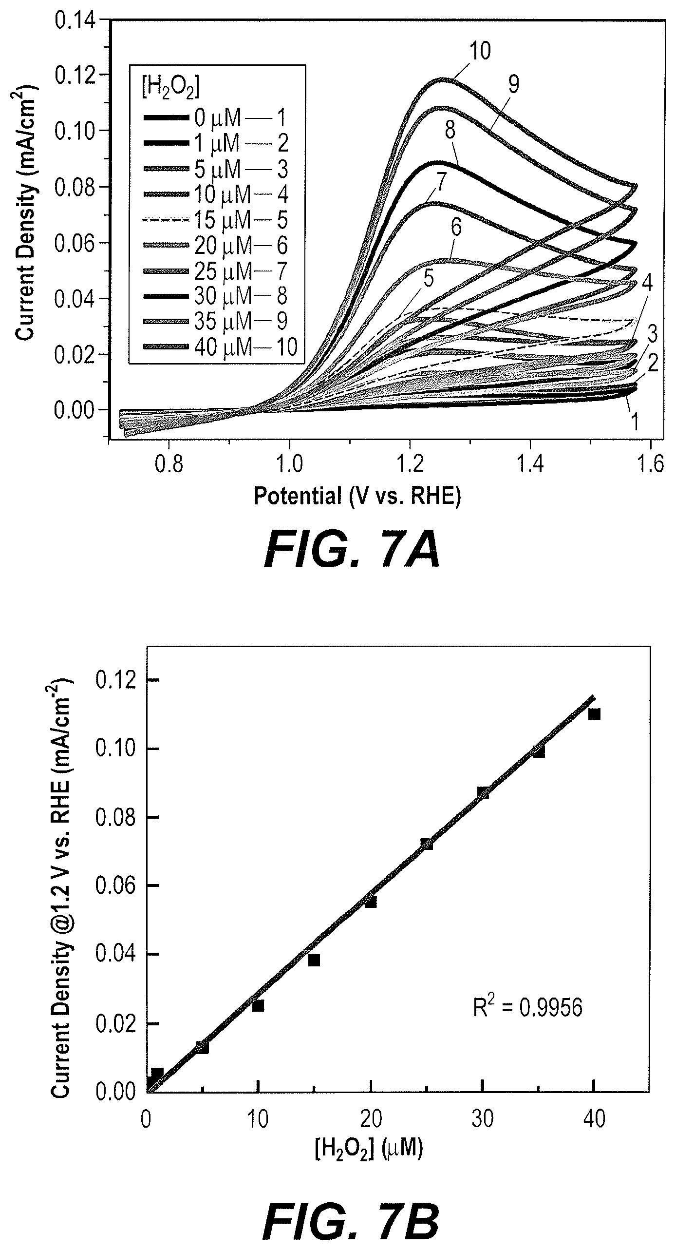
FIG. 7A is a composite CV voltammogram taken in alkaline solution comparing CV traces made upon sequential additions of M aliquots of H.sub.2O.sub.2 to the solution.
FIG. 7B is a plot of peak current as a function of H.sub.2O.sub.2 content/concentration based upon the traces in FIG. 7A.
FIG. 7C is a composite CV voltammogram taken in alkaline solution comparing CV traces made upon sequential additions of mM aliquots of H.sub.2O.sub.2 to the solution.
FIG. 7D is a plot of peak current as a function of H.sub.2O.sub.2 content/concentration based upon the traces in FIG. 7C.
FIG. 8A is a composite LSV voltammogram comparing LSV traces taken at different scan rates for a Bi.sub.2O.sub.3-x ND/FTO electrode in oxygen saturated alkaline solution.
FIG. 8B is a plot of peak currents as a function of the square root of the scan rate for the traces in FIG. 8A.
Similar reference characters denote corresponding features consistently throughout the attached drawings.
DETAILED DESCRIPTION OF THE PREFERRED EMBODIMENTS
The method of producing hydrogen peroxide using nanostructured bismuth oxide is an electrochemical method for producing and sensing hydrogen peroxide using a cathode formed as a nanostructured dendritic (ND) oxygen-deficient bismuth oxide (Bi.sub.2O.sub.3-x) electrode. The cathode is formed by depositing a bismuth film on a conducting substrate using an electrodeposition method, followed by annealing the bismuth film in air to oxidize bismuth to form a film of bismuth oxide (Bi.sub.2O.sub.3), and then annealing the bismuth oxide film under vacuum to partially reduce the bismuth oxide to form an oxygen-deficient reduced bismuth oxide (Bi.sub.2O.sub.3-x, where x is greater than 0 and less than 3) surface on the electrode. The cathode prepared in this manner and an anode are immersed in an alkaline medium saturated with oxygen to form an electrochemical cell for the production of H.sub.2O.sub.2.
Oxygen deficient nanodendrite Bi.sub.2O.sub.3-x electrodes were controllably prepared through electrodeposition of bismuth on FTO as an exemplary conductive substrate, followed by heat treatment in air to oxidize the bismuth and form bismuth oxide (Bi.sub.2O.sub.3), and then by annealing again under vacuum to create oxygen deficiency and reduce the bismuth oxide. Such electrodes will hereto for be referred to as Bi.sub.2O.sub.3-x ND/FTO electrodes. The effect of annealing gases on the surface chemistry of Bi.sub.2O.sub.3-x ND/FTO electrodes was examined by cyclic voltammetry (CV) and by scanning electron microscopy (SEM), and compared with Bi.sub.2O.sub.3 ND/FTO and conventional electrodes, with results shown in the drawings. The overvoltage to perform ORR by cyclic polarization using the exemplary fabricated Bi.sub.2O.sub.3-x ND/FTO electrodes is considerably reduced relative to when using the exemplary Bi.sub.2O.sub.3 ND/FTO electrodes. The exemplary Bi.sub.2O.sub.3-x ND/FTO electrodes result in efficient production of H.sub.2O.sub.2 at low overpotential.
The following details the particular materials and methods used in the exemplary implementation of the method. Bismuth (III) nitrate (Bi(NO.sub.3).sub.3.5H.sub.2O, .gtoreq.98.0%) and ethylene glycol (EG; HOCH.sub.2CH.sub.2OH, .gtoreq.99.8%) were acquired from Fisher Scientific. All chemicals were used as is. Electrodeposition was carried out in a one compartment cell via a VMP2 multichannel potentiostat system. A classical 3-electrode system comprising a fluoride-doped tin oxide (FTO) working electrode, an Ag/AgCl (4 M KCl) reference electrode, and a Pt counter electrode was used. Bi-metallic films were prepared starting with a 20 mM Bi(NO.sub.3).sub.3.5H.sub.2O solution in EG. The electrodeposition was performed by passing 0.1 C/cm.sup.2 at E=-1.8 V vs. Ag/AgCl, then resting for 2 s. The cycle was repeated 5 times to pass a total charge of 0.50 C/cm.sup.2. The electrodeposited Bi-metallic films were annealed at 450.degree. C. for 2 h in air after ramping to the target temperature of 450.degree. C. at a ramping rate of 3.0.degree. C./min to form Bi.sub.2O.sub.3 films. The Bi.sub.2O.sub.3 films were placed in a porcelain combustion boat and maintained at 350.degree. C. for various times (0.5 to 5.0 h) under vacuum to obtain Bi.sub.2O.sub.3-x films.
The fabricated materials were allowed to cool to room temperature under vacuum. The morphology of the electrodes was examined using FESEM (JSM-6380LA). Ultraviolet-visible diffuse reflectance spectroscopy (UV-DRS) measurements were performed using a Hitachi U-3010. The crystallinity and purity of exemplary electrodes fabricated as described herein were investigated by X-ray diffraction (XRD) on a Bruker D8-Advance Diffractometer via Cu Ka radiation (.lamda.=1.5418 .ANG.).
The theoretical value of the Levich slope (B) is evaluated from the following equation: B=0:62.times.n.times.F.times.C.sub.O2.times.D.sub.O2.sup.2/3.times..nu..s- up.-1/6 where n is the electron transfer number in ORR, F is the Faradic constant (96,485 C mol.sup.-1), C.sub.O2 is the saturated oxygen concentration in 0.1M NaOH aqueous solution (1.2.times.10.sup.-6 mol cm.sup.-3), D.sub.O2 is the oxygen diffusion coefficient (1.73.times.10.sup.-5 cm.sup.2 s.sup.-1) and .nu. is the kinematic viscosity of the solution (0.01 cm.sup.2 s.sup.-1).
The structure and morphology of the Bi-metallic film, Bi.sub.2O.sub.3 film, and Bi.sub.2O.sub.3-x film during the electrophoretic deposition and annealing processes in the fabrication of Bi.sub.2O.sub.3-x ND/FTO were characterized by SEM. FIG. 1A shows FESEM images of the Bi-metallic dendritic nanostructures electrodeposited (charge: 0.5 C cm.sup.-2) on an FTO substrate. The FESEM images show that nano-aggregates of deposited Bi form randomly arranged nanodendrites with a micro-nano hierarchical structure (see also FIG. 1B) suitable for electrochemical applications. Dendrites in the range of 1-2 .mu.m in length feature many nano-scaled dendrite side branches less than 200 nm in length. Bi ND/FTO electrodes are converted to Bi.sub.2O.sub.3 ND/FTO by annealing in air, as described previously, the resulting nanostructures being shown in FIG. 1C and further characterized by EDS analysis, as shown in FIG. 1D. After air annealing, the main branches appear to increase in length and the side branches exhibit more defined, leaf-like morphologies. In other words, well-defined nanodendrites are formed in the process of forming the Bi.sub.2O.sub.3 film. The FESEM image of a Bi.sub.2O.sub.3-x ND/FTO electrode shows no significant changes occur in morphology during vacuum annealing, as shown in FIG. 1E. The corresponding EDS analysis is provided in FIG. 1F.
The XRD diffractogram patterns of the Bi ND, Bi.sub.2O.sub.3 ND and Bi.sub.2O.sub.3-x ND films are shown in FIG. 2. The 2.theta. values may be compared with standard values to identify crystalline structures in the material. The diffraction peaks observed in Bi.sub.2O.sub.3 ND and Bi.sub.2O.sub.3-xND match well with the standard JCPDS card number 27-0050 of .beta.-Bi.sub.2O.sub.3, which crystallizes in a tetragonal system. The diffraction peaks of the Bi.sub.2O.sub.3 ND and Bi.sub.2O.sub.3-x ND samples can be indexed well to corresponding single phases, which crystallize in a tetragonal .beta.-Bi.sub.2O.sub.3 system (JCPDS No. 27-0050). The sharp diffraction peaks of Bi.sub.2O.sub.3 ND and Bi.sub.2O.sub.3-x ND indicate that each exhibits high crystallinity. However, in the case of Bi.sub.2O.sub.3-x ND, the diffraction peaks become much broader and weaker, which indicates its reduced crystallinity relative to the Bi.sub.2O.sub.3 ND.
The electrochemical activity of Bi.sub.2O.sub.3 ND and Bi.sub.2O.sub.3-x ND electrodes was further examined for application as catalysts in ORRs performed in O.sub.2-saturated alkaline solution. For the Bi.sub.2O.sub.3-x ND, annealing under vacuum was performed at 350.degree. C. for 120 min. FIG. 3 shows the results of cyclic voltammograms (CVs) for each of the exemplary electrodes performed at 50 mV s.sup.-1 in 0.1 M NaOH. In the presence of O.sub.2, the Bi.sub.2O.sub.3 ND electrode displays a low current plateau in the potential window from 0.2 to 1.5 V vs. RHE (reversible hydrogen electrode, used to calibrate the reference electrode). Further, the Bi.sub.2O.sub.3 ND electrode does not show any reduction peak in the measured potential region. In contrast, the Bi.sub.2O.sub.3-x ND electrode show well-defined reduction peaks at 0.45 V vs RHE. The Bi.sub.2O.sub.3-x ND electrode exhibits well-defined high redox peak currents, indicating greater electrochemical reversibility than the Bi.sub.2O.sub.3 ND electrode. The peak-to-peak separation for the Bi.sub.2O.sub.3-x ND electrode is estimated to be 0.75 V. In comparison to Bi.sub.2O.sub.3 ND electrodes, oxygen deficient Bi.sub.2O.sub.3-x ND electrodes produced by vacuum annealing of Bi.sub.2O.sub.3 ND show considerably enhanced electronic conductivity and reactivity in the ORR process. This could possibly, but without being bound by theory, be due to the large number of oxygen defects created, which provide oxygen vacancies that could serve as acceptors, resulting in semiconducting activity, thereby facilitating reactant adsorption and charge transfer.
During ORR, linear sweep voltammogram (LSV) measurements were carried out for the Bi.sub.2O.sub.3 ND electrode and the Bi.sub.2O.sub.3-x ND electrode, in comparison with state of the art Pt/C catalysts. Results of these measurements are presented in FIG. 4. FIG. 4 illustrates that the oxygen deficient Bi.sub.2O.sub.3-x ND electrodes provide significantly more electrocatalytic activity compared to Bi.sub.2O.sub.3 ND (but lower than Pt/C catalysts in the alkaline electrolyte), demonstrated by the more positive onset and half-wave potentials. Additionally, the different electrocatalytic behavior observed with Bi.sub.2O.sub.3-x ND/FTO and Bi.sub.2O.sub.3 ND/FTO electrodes during ORR indicates that more active ORR sites are available on the Bi.sub.2O.sub.3-x ND/FTO electrodes, possibly due to the available oxygen vacancies.
The oxygen reduction potentials are more positive for the Bi.sub.2O.sub.3-x ND electrode relative to the Bi.sub.2O.sub.3 ND and Pt/C electrodes, which suggests enhanced catalytic performance towards ORR.
To confirm the identity for the oxygen reduction peaks at the Bi.sub.2O.sub.3 ND and Bi.sub.2O.sub.3-x ND electrodes, the effect of oxygen concentration in alkaline media was examined by purging the medium with one of O.sub.2, air or N.sub.2. FIGS. 5A-5C show the CV traces taken at exemplary a Bi.sub.2O.sub.3 ND and Bi.sub.2O.sub.3-x ND electrodes in the different oxygen concentrations in 0.1 M NaOH. The CV for the Bi.sub.2O.sub.3-x ND electrodes in deoxygenated (N.sub.2) solution (FIG. 5A) shows no reduction peak in the measured region. The CV for the Bi.sub.2O.sub.3-x ND electrodes in moderate oxygen conditions (electrolyte solution purged with air, FIG. 5B) exhibits oxygen reduction peaks, and in high oxygen conditions (electrolyte purged with O.sub.2, FIG. 5C) shows further increased electrocatalytic current. Finally, these results suggest the observed peaks are due to the reduction of oxygen at Bi.sub.2O.sub.3-x ND electrodes, and we speculate that the reduction process at potential 0.46 V vs RHE, which corresponds to the reduction of O.sub.2 by two electrons to give H.sub.2O.sub.2 (or more correctly HO.sub.2.sup.-). Comparing the CV curves of Bi.sub.2O.sub.3-x ND electrodes and Bi.sub.2O.sub.3 ND electrodes, it appears that electrocatalytic reduction of oxygen on the electrode is more effective in the Bi.sub.2O.sub.3-x system, which provides greater cathodic current than Bi.sub.2O.sub.3 ND in 0.1 M NaOH aqueous electrolyte. In comparison with the Bi.sub.2O.sub.3 ND electrode, the increase of current response of Bi.sub.2O.sub.3-x suggests that generated oxygen vacancies play a main part in the electrochemical production of H.sub.2O.sub.2.
To determine the electrochemical response to H.sub.2O.sub.2, CV was performed in the absence and presence of 0.4 M H.sub.2O.sub.2, where Bi.sub.2O.sub.3 and Bi.sub.2O.sub.3-x electrodes were compared and are demonstrated in FIGS. 6A-6B. FIG. 6A shows the CVs with addition of 0.4 M H.sub.2O.sub.2 aliquots into 0.1 M NaOH solution at Bi.sub.2O.sub.3 ND electrode. The Bi.sub.2O.sub.3 ND electrode shows nearly no reduction behavior, demonstrating that the reduction of H.sub.2O.sub.2 was hardly attained at this electrode. In contrast, the Bi.sub.2O.sub.3-x ND electrode displays much greater response signals with much greater catalytic current and lowers the over potential value, as shown in FIG. 6B. This result clearly indicates that the oxygen deficient nature of Bi.sub.2O.sub.3-x plays a critical role in H.sub.2O.sub.2 reduction behavior.
FIG. 7A displays CVs taken with sequential addition of H.sub.2O.sub.2 aliquots in the range of 0-40 .mu.M into 0.1 M NaOH solution at Bi.sub.2O.sub.3-x ND electrodes. In N.sub.2 saturated 0.1 M NaOH, the reduction peak current of H.sub.2O.sub.2 increases gradually following the addition of H.sub.2O.sub.2 concentration. As shown in FIG. 7B, there is a good linear relationship between the peak current and H.sub.2O.sub.2 concentration in the range of 0.about.40 .mu.M (R=0.9957). FIG. 7C displays CVs taken with sequential addition of H.sub.2O.sub.2 aliquots in the range of 0-100 mM into 0.1 M NaOH solution at Bi.sub.2O.sub.3-x electrodes. FIG. 7D displays a good linear relationship between the peak current and H.sub.2O.sub.2 concentration at the range of 0.about.100 mM (R=0.984). Upon the continued addition of H.sub.2O.sub.2, remarkable current increase at the oxidation peak is observed, confirming the exceptional oxidizing effect of Bi.sub.2O.sub.3-x toward H.sub.2O.sub.2. In addition, the oxidation potential exhibits a slight positive shift, potentially signifying a kinetic limitation of the H.sub.2O.sub.2 oxidation reaction.
FIG. 8A displays the influence of the scan rate on the ORR process at Bi.sub.2O.sub.3-x ND electrodes in 0.1 M NaOH saturated with O.sub.2. Further, the association between the cathodic current and the square root of the scan rate is shown in FIG. 8B. For Bi.sub.2O.sub.3-x ND electrodes, both oxygen reduction peak currents increase linearly with the square root of potential scan rate, signifying that the overall ORR process at this electrode is dominated by the diffusion of O.sub.2 from solution to the oxygen vacancies at surface sites. Moreover, with increased H.sub.2O.sub.2 concentration, the reduction peak currents shifted toward more negative potentials, suggesting a possible kinetic limitation in the reaction between Bi.sub.2O.sub.3-x ND/FTO and H.sub.2O.sub.2.
The Bi.sub.2O.sub.3-x ND electrodes allow for production of H.sub.2O.sub.2 at low overpotentials. Annealing of metal oxides under vacuum is a simple, scalable and low cost way of creating oxygen vacancies to create highly efficient catalysts for H.sub.2O.sub.2 generation.
It is to be understood that the method of producing hydrogen peroxide using nanostructured bismuth oxide are not limited to the specific embodiments described above, but encompasses any and all embodiments within the scope of the generic language of the following claims enabled by the embodiments described herein, or otherwise shown in the drawings or described above in terms sufficient to enable one of ordinary skill in the art to make and use the claimed subject matter.
* * * * *
D00000
D00001
D00002
D00003
D00004
D00005
D00006
D00007
D00008
D00009
D00010
XML
uspto.report is an independent third-party trademark research tool that is not affiliated, endorsed, or sponsored by the United States Patent and Trademark Office (USPTO) or any other governmental organization. The information provided by uspto.report is based on publicly available data at the time of writing and is intended for informational purposes only.
While we strive to provide accurate and up-to-date information, we do not guarantee the accuracy, completeness, reliability, or suitability of the information displayed on this site. The use of this site is at your own risk. Any reliance you place on such information is therefore strictly at your own risk.
All official trademark data, including owner information, should be verified by visiting the official USPTO website at www.uspto.gov. This site is not intended to replace professional legal advice and should not be used as a substitute for consulting with a legal professional who is knowledgeable about trademark law.