Shelving assembly having an adjustable bridge shelf
Lim , et al.
U.S. patent number 10,681,978 [Application Number 16/183,291] was granted by the patent office on 2020-06-16 for shelving assembly having an adjustable bridge shelf. This patent grant is currently assigned to Seville Classics Inc.. The grantee listed for this patent is Seville Classics Inc.. Invention is credited to Gary Lim, James Sokol.


| United States Patent | 10,681,978 |
| Lim , et al. | June 16, 2020 |
Shelving assembly having an adjustable bridge shelf
Abstract
A closet organizer assembly has a first tower unit and a second tower unit, each tower unit having a plurality of shelves separated by vertical posts, each tower unit also having a plurality of top vertical posts, and a cantilevered shelf removably connected to the plurality of top vertical posts, with each cantilevered shelf having a border wall that includes a plurality of border wall openings. The assembly also includes a bridge shelf having a left end that is removably connected to the cantilevered shelf of the first tower unit, and a right end that is removably connected to the cantilevered shelf of the second tower unit.
| Inventors: | Lim; Gary (Palos Verdes Peninsula, CA), Sokol; James (Brea, CA) | ||||||||||
|---|---|---|---|---|---|---|---|---|---|---|---|
| Applicant: |
|
||||||||||
| Assignee: | Seville Classics Inc.
(Torrance, CA) |
||||||||||
| Family ID: | 70458115 | ||||||||||
| Appl. No.: | 16/183,291 | ||||||||||
| Filed: | November 7, 2018 |
Prior Publication Data
| Document Identifier | Publication Date | |
|---|---|---|
| US 20200138187 A1 | May 7, 2020 | |
| Current U.S. Class: | 1/1 |
| Current CPC Class: | A47B 96/021 (20130101); A47F 5/14 (20130101); A47B 47/04 (20130101); A47F 5/10 (20130101); A47B 45/00 (20130101); A47B 61/00 (20130101); A47F 5/0031 (20130101); A47B 47/021 (20130101); A47B 47/022 (20130101); A47B 47/0041 (20130101); A47F 5/13 (20130101); A47B 47/0058 (20130101); A47B 55/02 (20130101); A47B 47/027 (20130101); A47F 5/01 (20130101); A47B 87/001 (20130101); A47B 87/008 (20130101); A47B 47/0083 (20130101) |
| Current International Class: | A47B 61/00 (20060101); A47B 47/00 (20060101); A47B 47/04 (20060101); A47B 47/02 (20060101); A47B 96/02 (20060101); A47F 5/14 (20060101); A47F 5/01 (20060101); A47B 55/02 (20060101); A47B 87/00 (20060101); A47F 5/00 (20060101); A47F 5/10 (20060101); A47F 5/13 (20060101); A47B 45/00 (20060101) |
| Field of Search: | ;211/191,123,194,188,187,186,134,189,181.1,204,206,175 ;108/27,106-110,180,186,187,147.11 ;312/107,108,111,238 |
References Cited [Referenced By]
U.S. Patent Documents
| 3730601 | May 1973 | Misenheimer, III |
| 3756168 | September 1973 | Bushyhead |
| 3948581 | April 1976 | Heiman |
| 4099472 | July 1978 | Kellogg |
| 4805785 | February 1989 | Pfeifer |
| 4919280 | April 1990 | Phillips |
| 4928833 | May 1990 | Huizenga |
| 4934858 | June 1990 | Beaulieu |
| 5195642 | March 1993 | Dardashti |
| 5588541 | December 1996 | Goetz |
| 5601038 | February 1997 | Welch |
| 5752610 | May 1998 | Remmers |
| 5913270 | June 1999 | Price |
| 6230632 | May 2001 | Moore |
| 6644484 | November 2003 | Sardis |
| 8905247 | December 2014 | Artigues |
| 2002/0130098 | September 2002 | Simard |
| 2004/0256337 | December 2004 | Humberto |
| 2006/0054063 | March 2006 | Ryan, Jr. |
| 2006/0157435 | July 2006 | Oberhaus |
| 2006/0169659 | August 2006 | Robinson |
| 2007/0095773 | May 2007 | Schwerman |
| 2007/0108147 | May 2007 | Chen |
| 2007/0227994 | October 2007 | Cho |
| 2008/0302748 | December 2008 | Tsai |
| 2009/0184078 | July 2009 | Lee |
| 2011/0220602 | September 2011 | Chen |
| 2011/0233164 | September 2011 | Chang |
| 2012/0031863 | February 2012 | Horn |
| 2012/0298607 | November 2012 | Chen |
| 2014/0263135 | September 2014 | Sabounjian |
| 2014/0353271 | December 2014 | Kruse |
| 2016/0073774 | March 2016 | Lim |
| 2017/0065078 | March 2017 | Sabounjian |
| 2017/0215579 | August 2017 | Cooper |
Attorney, Agent or Firm: Sun; Raymond
Claims
What is claimed is:
1. A closet organizer assembly, comprising: a first tower unit and a second tower unit, each tower unit having a plurality of shelves separated by vertical posts, each tower unit having a plurality of top vertical posts, and a cantilevered shelf removably connected to the plurality of top vertical posts, each cantilevered shelf having at least one border wall having a plurality of border wall openings; a bridge shelf having a left end, a right end, and a central shelf section and having a front border frame and a rear border frame, each border frame defining a plurality of border frame openings; and a first connector assembly that removably connects the left end of the bridge shelf to the cantilevered shelf of the first tower unit, and a second connector assembly that removably connects the right end of the bridge shelf to the cantilevered shelf of the second tower unit, with each connector assembly having at least one rod that extends through an aligned pair of one border wall opening and one border frame opening.
2. The assembly of claim 1, wherein each connector assembly comprises a front plate having at least one rod, and a rear plate having an opening through the rod extends.
3. A closet organizer assembly, comprising: a first tower unit and a second tower unit, each tower unit having a plurality of shelves separated by vertical posts, each tower unit having a plurality of top vertical posts, and a cantilevered shelf removably connected to the plurality of top vertical posts, each cantilevered shelf having at least one border wall that includes a plurality of border wall openings; a bridge shelf having a left end that is removably connected to the cantilevered shelf of the first tower unit, and a right end that is removably connected to the cantilevered shelf of the second tower unit; and a hanging rod having a first end that is connected to one of the plurality of shelves in the first tower unit, and a second end that is connected to one of the plurality of shelves in the second tower unit, with the hanging rod positioned below the cantilevered shelves; wherein the bridge shelf further includes a central shelf section and having a front border frame and a rear border frame, each border frame defining a plurality of border frame openings.
4. The assembly of claim 3, further including a first connector assembly that removably connects the left end of the bridge shelf to the cantilevered shelf of the first tower unit, and a second connector assembly that removably connects the right end of the bridge shelf to the cantilevered shelf of the second tower unit, with each connector assembly having at least one rod that extends through an aligned pair of one border wall opening and one border frame opening.
5. The assembly of claim 4, wherein each connector assembly comprises a front plate having at least one rod, and a rear plate having an opening through the rod extends.
6. A closet organizer assembly, comprising: a first tower unit and a second tower unit, each tower unit having a plurality of shelves separated by vertical posts, each tower unit having a plurality of top vertical posts, and a cantilevered shelf removably connected to the plurality of top vertical posts, each cantilevered shelf having a front border wall and a rear border wall; a bridge shelf having a horizontal central shelf section, a left end, and a right end, with the central shelf section having a front edge and a rear edge, the bridge shelf further including a front vertical border frame provided along the front edge and a rear vertical border frame provided along the rear edge; wherein the front border wall is adapted to slide along and be retained interior to the front vertical border frame, and the rear border wall is adapted to slide along and be retained interior to the rear vertical border frame; and wherein the left end is removably connected to the cantilevered shelf of the first tower unit, and the right end that is removably connected to the cantilevered shelf of the second tower unit.
7. The assembly of claim 6, wherein each border frame is C-shaped and defines a rail track.
8. The assembly of claim 7, wherein each border frame has two horizontal strips and a vertical bordering wire.
9. The assembly of claim 8, wherein the bordering wire has a boundary, and a zig-zag wire is housed inside the boundary of the bordering wire and defining border frame openings.
10. The assembly of claim 6, further including a hanging rod having a first end that is connected to one of the plurality of shelves in the first tower unit, and a second end that is connected to one of the plurality of shelves in the second tower unit, with the hanging rod positioned below the cantilevered shelves.
11. The assembly of claim 6, wherein each border frame defines a plurality of border frame openings, and the border wall of each cantilevered shelf have a plurality of border wall openings, the assembly further including a first connector assembly that removably connects the left end of the bridge shelf to the cantilevered shelf of the first tower unit, and a second connector assembly that removably connects the right end of the bridge shelf to the cantilevered shelf of the second tower unit, with each connector assembly having at least one rod that extends through an aligned pair of one border wall opening and one border frame opening.
12. The assembly of claim 11, wherein each connector assembly comprises a front plate having at least one rod, and a rear plate having an opening through the rod extends.
Description
BACKGROUND OF THE INVENTION
1. Field of the Invention
The present invention relates to a shelving assembly, and in particular, to a shelving assembly that has two columns of shelves, and an adjustable bridge shelf that connects the two columns.
2. Description of the Related Art
"Knock-down" or portable shelving assemblies have become very popular. There are many different types of shelving assembles that can be adapted for use in many different locations around the house. One type of shelving assembly is a closet organizer assembly that has two tower units, and a bridge shelf that connects at the top to cantilevered shelves extending from each tower unit.
Because closets in different rooms come in different sizes, it is important for the user to be able to adjust the closet organizer assembly to fit the dimensions of the specific closets. In this regard, the length of the bridge shelf may need to be adjusted to fit the specific closet that it is to be used in. Thus, there remains a need for a closet organizer assembly that provides an adjustable bridge shelf that can be conveniently and effectively adjusted to fit into almost any closet.
SUMMARY OF THE INVENTION
To accomplish the objectives of the present invention, there is provided a closet organizer assembly having a first tower unit and a second tower unit, each tower unit having a plurality of shelves separated by vertical posts, each tower unit having a plurality of top vertical posts, and a cantilevered shelf removably connected to the plurality of top vertical posts, with each cantilevered shelf having a border wall that includes a plurality of border wall openings. The assembly also includes a bridge shelf having a left end that is removably connected to the cantilevered shelf of the first tower unit, and a right end that is removably connected to the cantilevered shelf of the second tower unit.
In one embodiment of the present invention, a hanging rod is provided, and has a first end that is connected to one of the plurality of shelves in the first tower unit, and a second end that is connected to one of the plurality of shelves in the second tower unit, with the hanging rod positioned below the cantilevered shelves.
In another embodiment, the bridge shelf includes a central shelf section, a front border frame and a rear border frame, with each border frame defining a plurality of border frame openings. A first connector assembly removably connects the left end of the bridge shelf to the cantilevered shelf of the first tower unit, and a second connector assembly removably connects the right end of the bridge shelf to the cantilevered shelf of the second tower unit, with each connector assembly having at least one rod that extends through an aligned pair of one border wall opening and one border frame opening.
In another embodiment, the bridge shelf has a horizontal central shelf section, a left end, and a right end, with the central shelf section having a front edge and a rear edge. The bridge shelf further includes a front vertical border frame provided along the front edge and a rear vertical border frame provided along the rear edge, with the front border wall adapted to slide along and be retained interior to the front vertical border frame, and the rear border wall adapted to slide along and be retained interior to the rear vertical border frame.
BRIEF DESCRIPTION OF THE DRAWINGS
FIG. 1 is a perspective view of a closet assembly according to the present invention.
FIG. 2 is a perspective view of the closet assembly of FIG. 1 shown without the bridge shelf.
FIG. 3 is a perspective view of the closet assembly of FIG. 1 shown with the bridge shelf partially installed.
FIG. 4 is a perspective view of the bridge shelf of the present invention.
FIG. 5 is a perspective view of a cantilevered shelf of the present invention.
FIG. 6 is an exploded view of the connector assembly of the present invention.
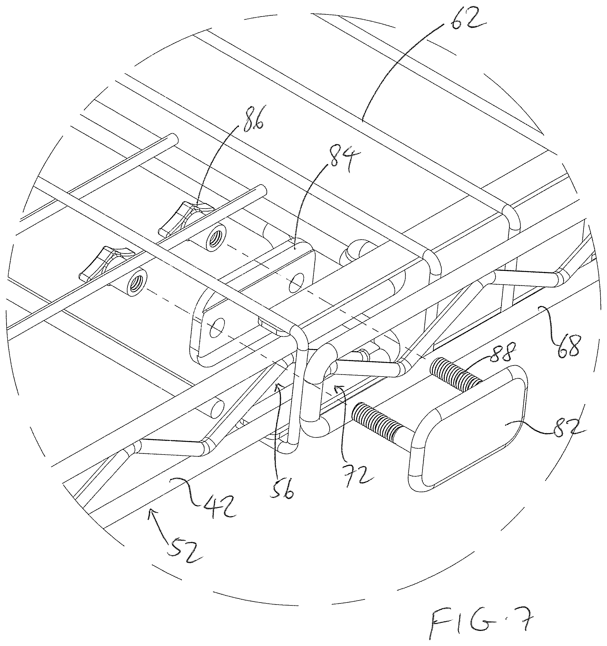
FIG. 7 illustrates how the connector assembly of FIG. 6 is used to adjustably connect one end of the bridge shelf to one cantilevered shelf.
DESCRIPTION OF THE PREFERRED EMBODIMENTS
The following detailed description is of the best presently contemplated modes of carrying out the invention. This description is not to be taken in a limiting sense, but is made merely for the purpose of illustrating general principles of embodiments of the invention. The scope of the invention is best defined by the appended claims.
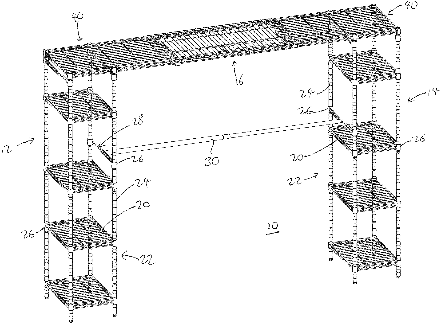
As shown in FIGS. 1-5, the closet organizer 10 according to the present invention has a left tower unit 12 and a right tower unit 14 that is interconnected at the top by a bridge shelf 16.
Each tower unit 12 and 14 is identical, and has a plurality of shelves 20 that are spaced apart along the height of a frame 22. The frame 22 includes a plurality of vertical posts 24 that has opposing ends that are removably connected to shelf collars or connectors 26 provided at the corners of each shelf 20. Each connector 26 can be configured in the form of an open cylinder having two opposite open ends that function as connector joints, one on top of, and one below, the connector 26, so that each connector joint receives an end of a vertical post 24. The vertical posts 24 can be provided in different lengths to allow the user to vary the distance or height between adjacent shelves 20. In addition, it is possible to provide an end support 28 for a hanging rod 30. The end support 28 can also include two connectors 26 that allow the vertical posts 24 to be removably connected thereto. Alternatively, the opposite first and second ends of the hanging rod 30 can be connected directly to opposite and height-aligned shelves 20 on the two tower units 12, 14.
Each shelf 20 can be provided in the form of a wire shelf having a frame or border with wires extending across the border. The border and the wires can be made from one of a variety of materials, including a metal (e.g., stainless steel), a plastic, a type of resin, wood or bamboo. Each shelf can also have a rectangular or square shape, and can be provided in any desired size.
A cantilevered shelf 40 is removably coupled to the top of each tower unit 12, 14. Referring to FIG. 5, the cantilevered shelf 40 can also have a border 42 with shelf collars or connectors 26 provided at the locations corresponding to the top four vertical posts 24 in each tower unit 12, 14. Wires 44 can extend across the border 42. The border 42 can have a short border wall that is defined by a wavy (e.g., sinusoidal) or zig-zag wire 46 that is retained between an upper wire 48 and a lower wire 50, and which functions as a truss wire. Openings 56 are defined by the upper wire 48, the lower wire 50, and the zig-zags in the zig-zag wire 46. An extension section 52 can extend from the main part 54 of the cantilevered shelf 40, and is adapted to removably connect to the bridge shelf 16.
Referring to FIG. 4, the bridge shelf 16 has a central shelf section 60 that is made up of a plurality of parallel transverse wires 62 supported by one or more longitudinal wires 64. The wires 62, 64 can be made of the same material as the wires for the shelves 20 and 40. The opposite end of each wire 62 is bent by ninety degrees to define a front border and a rear border for the bridge shelf 16. A border frame 66 is provided along the front border and the rear border. Each border frame 66 is generally C-shaped, and has two horizontal strips 74 and 76, and a vertical bordering wire 68. A zig-zag wire 70 is housed inside the boundary of the bordering wire 68 and functions as a truss wire. Openings 72 are defined by the bordering wire 68 and the zig-zags in the zig-zag wire 70. The strips 74 and 76 can be elongated strips of metal material that are connected (e.g., welded) to portions of the wires 62, with the upper strip 74 positioned on the underside of the wires 62 along the central shelf section 60, and the lower strip 76 positioned inside the bent ends of the wires 62. The two opposing C-shaped border frames 66 are adapted to function as opposing rail for the borders 42 of the cantilevered shelves 40.
FIG. 6 illustrates the connector assembly 80 that is used to removably connect the bridge shelf 16 to the cantilevered shelves 40. Four connector assemblies are needed, as two connector assemblies 80 are needed to connect opposing front and rear borders of the bridge shelf 16 to each cantilevered shelf 40. Each connector assembly 80 has one front plate 82, one rear plate 84, and two bolts 86. Two threaded bolts 88 extend from the rear of the front plate 82, and each extends through a corresponding opening 90 in the rear plate 84, before being secured by a threaded nut 92 of a corresponding bolt 86. Even though the present invention is being described as having threaded bolts 88, any rod-like element or clip mechanism that can extend through openings can also be used.
In use, the user unpacks all the shelves 16, 20 and 40 and the posts 24 from the box packaging, and begins assembly. The tower units 12 and 14 are assembled first by connecting ends of the posts 24 into the joints of the connectors 26. One cantilevered shelf 40 is then connected to the top of each tower unit 12, 14 in a manner where the extension sections 52 extend towards each other. See FIG. 2.
Next, the extension section 52 for one tower unit 12 or 14 is slid into the C-shaped border frames 66 of the bridge shelf 16. Specifically, one end of the bridge shelf 16 can be slid over the extension section 52 so that the borders 42 of that extension section 52 will slide into the rail track defined by the two C-shaped border frames 66. The same step is repeated for the other end of the bridge shelf 16 over the other extension section 52 for the other tower unit 14 or 12. Therefore, the front and rear border frames 66 of the bridge shelf 16 are positioned outside, or exterior to, the border 42 of the extension sections 52. Portions of the ends of the central shelf 60 will overlap, or lie on top of, portions of the extension sections 52, as best shown in FIGS. 1 and 3. The position of the bridge shelf 16 on top of the extension sections 52 can be adjusted by sliding the cantilevered shelves 40 along the rail track, depending on the size of the closet or room that the closet organizer 10 is to be used in.
Now, referring to FIG. 7, two sets of openings 56 and 72 are aligned, and a rear plate 84 is positioned interior of (inside) the border 42 of the extension section 52, and then a front plate 82 is positioned outside the border frame 66, with each threaded bolt 88 extending through adjacent sets of aligned openings 56 and 72, and through the openings 90 in the rear plate 84. The threaded nuts 86 are then used to secure the front plate 82 to the rear plate 84, thereby securing the bridge shelf 16 to the cantilevered shelf 40 at the specific location. Connector assemblies 80 can be used to secure the front and rear connections for each end of the bridge shelf 16 with each cantilevered shelf 40.
Thus, the present invention provides a closet organizer 10 which has a bridge shelf 16 that can be quickly installed on to the top thereof for use in a closet or room of any size. The connector assembly 80 and the alignment of the openings 56 and 72 in the border walls of the cantilevered shelves 40 and the bridge shelf 16 provide a simple yet effective way of allowing the user to adjust the position of the bridge shelf 16.
While the description above refers to particular embodiments of the present invention, it will be understood that many modifications may be made without departing from the spirit thereof.
* * * * *
D00000
D00001
D00002
D00003
D00004
D00005
D00006
D00007
XML
uspto.report is an independent third-party trademark research tool that is not affiliated, endorsed, or sponsored by the United States Patent and Trademark Office (USPTO) or any other governmental organization. The information provided by uspto.report is based on publicly available data at the time of writing and is intended for informational purposes only.
While we strive to provide accurate and up-to-date information, we do not guarantee the accuracy, completeness, reliability, or suitability of the information displayed on this site. The use of this site is at your own risk. Any reliance you place on such information is therefore strictly at your own risk.
All official trademark data, including owner information, should be verified by visiting the official USPTO website at www.uspto.gov. This site is not intended to replace professional legal advice and should not be used as a substitute for consulting with a legal professional who is knowledgeable about trademark law.