Battery system for vehicle
Hong , et al.
U.S. patent number 10,680,298 [Application Number 15/744,684] was granted by the patent office on 2020-06-09 for battery system for vehicle. This patent grant is currently assigned to LG CHEM, LTD.. The grantee listed for this patent is LG CHEM, LTD.. Invention is credited to Sung Gi Hong, Ho Yul Jeong, Geun Jeong Kim, Kwang Min Kim, Jae Kwon Lim, Nam Hyun Park.


| United States Patent | 10,680,298 |
| Hong , et al. | June 9, 2020 |
Battery system for vehicle
Abstract
The present invention relates to a battery system for a vehicle, which comprises: a battery pack installed in a trunk room of the vehicle and provided with a plurality of battery cells and an electrolyte; a cooling device circulating cooling water to cool an engine installed in the vehicle; and a safety device that injects the cooling water of the cooling device into the battery pack to cool the battery pack through impregnation of the cooling water to the plurality of battery cells when a temperature of the battery pack increases to a preset temperature or more.
| Inventors: | Hong; Sung Gi (Daejeon, KR), Kim; Kwang Min (Daejeon, KR), Lim; Jae Kwon (Daejeon, KR), Jeong; Ho Yul (Daejeon, KR), Park; Nam Hyun (Daejeon, KR), Kim; Geun Jeong (Daejeon, KR) | ||||||||||
|---|---|---|---|---|---|---|---|---|---|---|---|
| Applicant: |
|
||||||||||
| Assignee: | LG CHEM, LTD. (Seoul,
KR) |
||||||||||
| Family ID: | 59744163 | ||||||||||
| Appl. No.: | 15/744,684 | ||||||||||
| Filed: | February 13, 2017 | ||||||||||
| PCT Filed: | February 13, 2017 | ||||||||||
| PCT No.: | PCT/KR2017/001549 | ||||||||||
| 371(c)(1),(2),(4) Date: | January 12, 2018 | ||||||||||
| PCT Pub. No.: | WO2017/150818 | ||||||||||
| PCT Pub. Date: | September 08, 2017 |
Prior Publication Data
| Document Identifier | Publication Date | |
|---|---|---|
| US 20180212287 A1 | Jul 26, 2018 | |
Foreign Application Priority Data
| Mar 3, 2016 [KR] | 10-2016-0025586 | |||
| Current U.S. Class: | 1/1 |
| Current CPC Class: | B60L 58/26 (20190201); H01M 10/625 (20150401); H01M 10/635 (20150401); H01M 10/6568 (20150401); H01M 10/663 (20150401); B60L 3/00 (20130101); B62D 25/08 (20130101); B60L 50/60 (20190201); H01M 10/613 (20150401); H01M 10/63 (20150401); H01M 2220/20 (20130101) |
| Current International Class: | H01M 10/625 (20140101); H01M 10/613 (20140101); H01M 10/663 (20140101); H01M 10/635 (20140101); H01M 10/6568 (20140101); H01M 10/63 (20140101); B60L 3/00 (20190101); B60L 50/50 (20190101); B60L 58/26 (20190101); B62D 25/08 (20060101) |
References Cited [Referenced By]
U.S. Patent Documents
| 2006/0169507 | August 2006 | Inoue et al. |
| 2010/0047681 | February 2010 | Mitsui |
| 2012/0263988 | October 2012 | Obasih |
| 2013/0017421 | January 2013 | Onnerud |
| 2014/0342201 | November 2014 | Andres |
| 2 804 188 | Nov 2014 | EP | |||
| 2 851 973 | Mar 2015 | EP | |||
| S59-79964 | May 1984 | JP | |||
| 6-24238 | Feb 1994 | JP | |||
| 9-130917 | May 1997 | JP | |||
| 2006-216303 | Aug 2006 | JP | |||
| 2008-166169 | Jul 2008 | JP | |||
| 2008-290636 | Dec 2008 | JP | |||
| 2010-277737 | Dec 2010 | JP | |||
| 2011-173543 | Sep 2011 | JP | |||
| 2013-237355 | Nov 2013 | JP | |||
| 10-2012-0069334 | Jun 2011 | KR | |||
| 10-2015-0062783 | Jun 2015 | KR | |||
Other References
|
European Search Report for Appl. No. 17760222.4 dated May 11, 2018. cited by applicant . International Search Report for PCT/KR2017/001549 (PCT/ISA/210) dated Apr. 28, 2017. cited by applicant. |
Primary Examiner: Amponsah; Osei K
Attorney, Agent or Firm: Birch, Stewart, Kolasch & Birch, LLP
Claims
The invention claimed is:
1. A battery system for a vehicle, comprising: a battery pack installed in a trunk room of the vehicle and provided with a plurality of battery cells and an electrolyte; a cooling device configured to circulate cooling water to cool an engine installed in the vehicle; a safety device having an injection tube configured to inject the cooling water of the cooling device into the battery pack to cool the battery pack through impregnation of the cooling water to the plurality of battery cells when a temperature of the battery pack increases to a preset temperature or more; a felt having fine holes located in the battery pack near the injection tube; and a material comprising salt being provided in the felt, the material being dissolvable into the cooling water injected into the battery pack to increase electrical conductivity.
2. A battery system for a vehicle, comprising: a battery pack installed in a trunk room of the vehicle and provided with a plurality of battery cells and an electrolyte; a cooling device circulating cooling water to cool an engine installed in the vehicle; a safety device that injects the cooling water of the cooling device into the battery pack to cool the battery pack through impregnation of the cooling water to the plurality of battery cells when a temperature of the battery pack increases to a preset temperature or more, the safety device including: an injection tube through which the cooling water of the cooling device is injected into the battery pack; a switching valve that switches an opening and closing of the injection tube; a temperature sensor detecting a temperature of the battery pack; and a controller that opens the switching valve to inject the cooling water of the cooling device into the battery pack when the temperature of the battery pack, which is detected by the temperature sensor, is above the preset temperature, a felt having fine holes located in the battery pack near the injection tube; and a material comprising salt being provided in the felt, the material being dissolvable into the cooling water injected into the battery pack to increase electrical conductivity.
3. The battery system of claim 1, wherein the battery pack comprises a check valve that discharges air within the battery pack to the outside.
4. The battery system of claim 2, wherein the battery pack comprises a check valve that discharges air within the battery pack to the outside.
Description
CROSS-REFERENCE TO RELATED APPLICATION
The present application claims the benefit of the priority of Korean Patent Application No. 10-2016-0025586, filed on Mar. 3, 2016, which is hereby incorporated by reference in its entirety.
TECHNICAL FIELD
The present invention relates to a battery system for a vehicle, and more particularly, to a battery system for a vehicle, which prevents a battery pack from being ignited through cooling water for cooling an engine of the vehicle to improve safety.
BACKGROUND ART
In general, secondary batteries refer to chargeable and dischargeable, unlike primary batteries that are not chargeable. The secondary batteries are being widely used for mobile phones, notebook computers, and camcorders, electric vehicles, and the like. Among them, a secondary battery used in an electric vehicle uses a battery pack in which two or more battery cells are connected in parallel or in series.
DISCLOSURE OF THE INVENTION
Technical Problem
The battery pack for the vehicle according to the related art may cause fire and explosion when burn-out of the battery pack occurs by a fatal external impact such as collision of a vehicle. Also, when the short circuit occurs due to circuit problems in the battery pack, the fire and explosion may occur.
The present invention has been made to solve the above problems, and thus an object of the present invention is to provide a battery system for a vehicle, which prevents the battery pack from being exploded by injecting cooling water for cooling an engine of the vehicle into the battery pack to suppress an occurrence of the explosion of the battery pack when problems of the battery pack occur due an external impact or short circuit.
Technical Solution
To achieve the abovementioned object, a battery system for a vehicle according to the present invention comprises: a battery pack installed in a trunk room of the vehicle and provided with a plurality of battery cells and an electrolyte; a cooling device circulating cooling water to cool an engine installed in the vehicle; and a safety device that injects the cooling water of the cooling device into the battery pack to cool the battery pack through impregnation of the cooling water to the plurality of battery cells when a temperature of the battery pack increases to a preset temperature or more.
The safety device may comprise: an injection tube through which the cooling water of the cooling device is injected into the battery pack; a switching valve that switches an opening and closing of the injection tube; a temperature sensor detecting a temperature of the battery pack; and a controller that opens the switching valve to inject the cooling water of the cooling device into the battery pack when the temperature of the battery pack, which is detected by the temperature sensor, is above the preset temperature.
A material that is dissolved into the cooling water injected into the battery pack and increases electrical conductivity may be provided in the battery pack.
The material that increases the electrical conductivity may comprise salt.
The material that increases the electrical conductivity may be provided in the battery pack, in which the injection tube is disposed, in a state of being built in felt having fine holes.
The battery pack may comprise a check valve that discharges air within the battery pack to the outside.
Advantageous Effects
According to the present invention, since the battery pack is cooled by using the cooking water for cooling the engine provided in the vehicle, the battery pack may be prevented from being exploded by the external or internal factors. Particularly, the cooling water of the vehicle may be used to significantly reduce the manufacturing costs.
Also, according to the present invention, the material that is capable of increasing the electrical conductivity may be provided in the battery pack to quickly discharge the battery pack by the material, which is capable of increasing the electrical conductivity, together with the cooling water, thereby previously preventing the accidents that may occur later due to the battery pack from being occurring.
BRIEF DESCRIPTION OF THE DRAWINGS
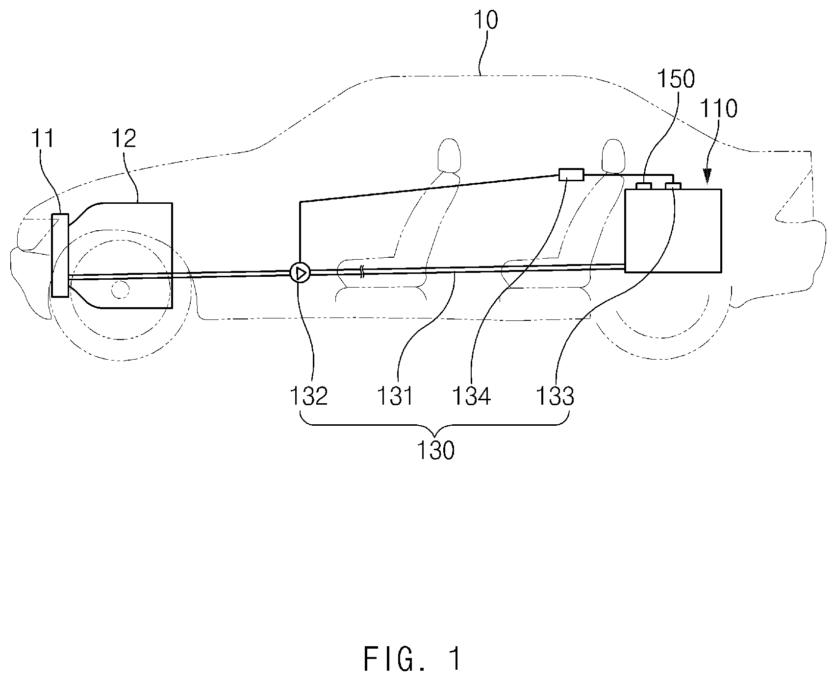
FIG. 1 is a view of a battery system for a vehicle according to the present invention.
FIG. 2 is an enlarged view of the battery system for the vehicle according to the present invention.
FIG. 3 is a view of the battery system for the vehicle, which comprises a material that increases electrical conductivity according to the present invention.
NODE FOR CARRYING OUT THE INVENTION
Hereinafter, embodiments of the present invention will be described in detail with reference to the accompanying drawings in such a manner that the technical idea of the present invention may easily be carried out by a person with ordinary skill in the art to which the invention pertains. The present invention may, however, be embodied in different forms and should not be construed as limited to the embodiments set forth herein. In the drawings, anything unnecessary for describing the present invention will be omitted for clarity, and also like reference numerals in the drawings denote like elements.
As illustrated in FIG. 1, a battery system for a vehicle according to the present invention comprises a battery pack 110 installed in a trunk room 11 of a vehicle 10 and provided with a plurality of battery cells 111 and an electrolyte 112, a cooling device 120 circulating cooling water to cool an engine 12 installed in the vehicle 10, and a safety device 130 that injects the cooling water of the cooling device 120 into the battery pack 110 to cool the battery pack 110 through impregnation of the cooling water to the plurality of battery cells 111 when a temperature of the battery pack 110 increases to a preset temperature or more.
The battery system for the vehicle according to the present invention may drive the engine 12 or electronic devices such as lighting devices of the vehicle by using electric energy generated in the battery pack 110. Here, when the engine 12 is driven, high-temperature heat may be generated. The high-temperature heat of the engine 12 may be cooled while the cooling water of the cooing device 120 circulates around the engine 12.
Here, when a collision accident of the vehicle 10 occurs, the vehicle 10 may be buckled to cause deformation of the battery pack 110. Here, a circuit connected to the plurality of battery cells 111 provided in the battery pack 110 may be short-circuited or ignited due to the short circuit to cause explosion of the vehicle 10.
To solve the above problems, the battery system for the vehicle according to the present invention may comprises the safety device 130 that injects the cooling water of the cooling device 120 into the battery pack 110 to suppress the short circuit and ignition of the battery pack 110 when a temperature of the battery pack 110 increases to the preset temperature or more. The safety device 130 may previously prevent the vehicle 10 from being exploded.
That is, the safety device 130 provided in the battery system for the vehicle according to the present invention comprises an injection tube 131 connecting the cooling device 120 to the battery pack 110 to inject the cooling water of the cooling device 120 into the battery pack 110, a switching valve 132 that switches an opening and closing of the injection tube 131, a temperature sensor 133 detecting a temperature of the battery pack 110, and a controller 134 that opens the switching valve 132 to inject the cooling water of the cooling device 120 into the battery pack 110 when the temperature of the battery pack 110, which is detected by the temperature sensor 133, is above the preset temperature. Here, the preset temperature may range from 50.degree. C. to 100.degree. C.
The safety device 130 comprises a check valve 150 that discharges air within the battery pack 110 to the outside and also blocks introduction of external air into the battery pack 110.
That is, when the cooling water is injected into the battery pack 110, the air within the battery pack 110 may be discharged to the outside through the check valve 150. Thus, the cooling water may be more quickly injected into the battery pack 110.
As described above, in the safety device 130 provided in the battery system for the vehicle according to the present invention, when the battery pack 110 increases in temperature by collision of the vehicle, the temperature sensor 133 detects the increasing temperature of the battery pack 110 to transmit the temperature value to the controller 134, and then, the controller 134 compares the temperature of the battery pack 110, which is detected by the temperature sensor 133, with the preset temperature. Here, when the temperature of the battery pack 110 is above the preset temperature, the controller 134 determines that a problem occurs in the battery pack 110 to open the switching valve 132. As a result, the cooling water of the cooling device 120 is injected into the battery pack 110 through the injection tube 131, and the cooling water injected into the battery pack 110 is mixed with the electrolyte 112 and simultaneously impregnated into the plurality of battery cells 111 to suppress the short circuit and the ignition. Particularly, the circuit within the battery pack 110 is sunk into the cooling water to prevent the circuit from being ignited due to the short circuit.
That is, while the cooling water is injected into the battery pack 110, the temperature of the battery pack 110 is cooled to a temperature less than the preset temperature to prevent the battery pack and the vehicle from being exploded.
Here, the air within the battery pack 110 may be discharged to the check valve 150, and thus, the cooling water may be more quickly injected.
When the vehicle in which the collision accident occurs is left for a long time, the cooling water injected into the battery pack 110 may be discharged to the outside of the battery pack 110 and thus removed. Here, when the cooling water injected into the battery pack 110 is removed, the short circuit may occur again due to energy remaining in the battery cells of the battery pack 110.
To prevent this phenomenon, the battery system for the vehicle according to the present invention may quickly consume the energy remaining the battery cells while cooling the battery cells to previously prevent an accident that may occur later from occurring.
That is, in the battery system for vehicle according to the present invention, a material 140, which increases electrical conductivity for maximizing properties of the electrolyte 112 while being dissolved into the cooling water injected into the battery pack 110, is provided in the battery pack 110. The material that is capable of increasing the electrical conductivity may be provided in the battery pack 110 in which the injection tube 131 is disposed and gradually dissolved into the cooling water injected into the battery pack 110 through the injection tube 131. Then, the material together with the cooling water may be mixed with the electrolyte to maximize the properties of the electrolyte 112 and thereby to quickly consume the energy of the battery cells 111, thereby discharging the battery cells 111. Here, the material 140 that increases the electrical conductivity may be salt.
The material 140 that increases the electrical conductivity may be provided in the battery pack 110 in a state in which the material 140 is built in felt 141 having fine holes. Thus, a storage property of the material 140 that increases the electrical conductivity may be improved.
Also, the check valve 150 that discharges a gas generated in the battery pack 110 to the outside may be provided in the battery pack 110. The check valve 150 may discharge the gas generated in the battery pack 110 to the outside to previously prevent the battery pack 110 from being exploded, and particularly, to prevent the inside of the battery pack 110 from being contaminated due to the introduction of external air and foreign substances.
Thus, in the battery system for the vehicle according to the present invention, the cooling water of the cooling device 120 that cools the engine 12 of the vehicle may be directly supplied into the battery pack 110 to cool the battery pack 110, thereby previously preventing the accident due to the battery pack 110 from occurring.
Accordingly, the scope of the present invention is defined by the appended claims rather than the foregoing description and the exemplary embodiments described therein. Various modifications made within the meaning of an equivalent of the claims of the invention and within the claims are to be regarded to be in the scope of the present invention.
* * * * *
D00000
D00001
D00002
D00003
XML
uspto.report is an independent third-party trademark research tool that is not affiliated, endorsed, or sponsored by the United States Patent and Trademark Office (USPTO) or any other governmental organization. The information provided by uspto.report is based on publicly available data at the time of writing and is intended for informational purposes only.
While we strive to provide accurate and up-to-date information, we do not guarantee the accuracy, completeness, reliability, or suitability of the information displayed on this site. The use of this site is at your own risk. Any reliance you place on such information is therefore strictly at your own risk.
All official trademark data, including owner information, should be verified by visiting the official USPTO website at www.uspto.gov. This site is not intended to replace professional legal advice and should not be used as a substitute for consulting with a legal professional who is knowledgeable about trademark law.