Method for detecting an unsealed location in a heat recovery system of an internal combustion engine
Neunteufl , et al.
U.S. patent number 10,677,678 [Application Number 15/754,521] was granted by the patent office on 2020-06-09 for method for detecting an unsealed location in a heat recovery system of an internal combustion engine. This patent grant is currently assigned to AVL List GmbH, FPT Industrial S.P.A., Iveco S.P.A.. The grantee listed for this patent is AVL LIST GMBH, FPT INDUSTRIAL S.P.A., IVECO S.P.A.. Invention is credited to Helmut Altendorfer, Fabio Cococcetta, Thomas Eckhardt, Gerald Gradwohl, Klemens Neunteufl.

| United States Patent | 10,677,678 |
| Neunteufl , et al. | June 9, 2020 |
Method for detecting an unsealed location in a heat recovery system of an internal combustion engine
Abstract
The invention relates to a method for detecting an unsealed location in a heat recovery system (5) of an internal combustion engine (1) of a motor vehicle. The heat recovery system (5) has at least one combustible working medium, a working medium circuit (6) with at least one EGR evaporator (7), a pump (8), and at least one expansion machine (9). The aim of the invention is to allow an early and reliable detection of leakages in the EGR evaporator (7) of a heat recovery system (5) in the simplest manner possible. This is achieved in that the internal combustion engine (1) is operated in the overrun mode, the oxygen concentration in the exhaust gas is ascertained and compared with a defined lower threshold, and if the lower threshold is undershot, a leakage in the EGR evaporator (7) is detected.
| Inventors: | Neunteufl; Klemens (Graz, AT), Gradwohl; Gerald (Graz, AT), Altendorfer; Helmut (Peilstein/Muhl, AT), Cococcetta; Fabio (Zurich, CH), Eckhardt; Thomas (Romanshorn, CH) | ||||||||||
|---|---|---|---|---|---|---|---|---|---|---|---|
| Applicant: |
|
||||||||||
| Assignee: | AVL List GmbH (Graz,
AT) Iveco S.P.A. (Turin, IT) FPT Industrial S.P.A. (Turin, IT) |
||||||||||
| Family ID: | 56320668 | ||||||||||
| Appl. No.: | 15/754,521 | ||||||||||
| Filed: | August 19, 2016 | ||||||||||
| PCT Filed: | August 19, 2016 | ||||||||||
| PCT No.: | PCT/AT2016/050254 | ||||||||||
| 371(c)(1),(2),(4) Date: | February 22, 2018 | ||||||||||
| PCT Pub. No.: | WO2017/035547 | ||||||||||
| PCT Pub. Date: | March 09, 2017 |
Prior Publication Data
| Document Identifier | Publication Date | |
|---|---|---|
| US 20180252609 A1 | Sep 6, 2018 | |
Foreign Application Priority Data
| Aug 28, 2015 [AT] | 50744/2015 | |||
| Current U.S. Class: | 1/1 |
| Current CPC Class: | F02D 41/123 (20130101); G01M 3/025 (20130101); F02D 41/146 (20130101); F02D 41/22 (20130101); F02D 41/1454 (20130101); F02D 41/005 (20130101); Y02T 10/47 (20130101); Y02T 10/40 (20130101) |
| Current International Class: | G01M 3/02 (20060101); F02D 41/22 (20060101); F02D 41/12 (20060101); F02D 41/14 (20060101); F02D 41/00 (20060101) |
References Cited [Referenced By]
U.S. Patent Documents
| 6526358 | February 2003 | Mathews et al. |
| 6568246 | May 2003 | Ponagai |
| 6752128 | June 2004 | Ozeki |
| 10024159 | July 2018 | Glensvig |
| 2003/0230287 | December 2003 | Ozeki |
| 2010/0313565 | December 2010 | Kaplan |
| 2015/0120133 | April 2015 | Dudar et al. |
| 2017/0138302 | May 2017 | Leon-Rovira |
| 2017/0152766 | June 2017 | Andersson |
| 2017/0335783 | November 2017 | Cakallik |
| 2018/0156143 | June 2018 | Hussain |
| 2019/0242274 | August 2019 | Glensvig |
| 2010156314 | Jul 2010 | JP | |||
Other References
|
IP.Com English Translation of JP 201010156314 (Year: 2010). cited by examiner . English Abstract of JP 2010156314. 2010. cited by applicant. |
Primary Examiner: Fitzgerald; John
Attorney, Agent or Firm: Dykema Gossett PLLC
Claims
The invention claimed is:
1. A method for recognizing a leak in a heat-recovery system of an internal combustion engine of a motor vehicle, wherein the heat-recovery system comprises at least one combustible working medium, a working medium circuit with at least one EGR evaporator, a pump and at least one expansion machine, the method including the following steps: operating the internal combustion engine in motor-braking mode; determining an oxygen concentration in an exhaust gas of the internal combustion engine; comparing the determined oxygen concentration with a defined bottom threshold value; and recognizing the leakage in the at least one EGR evaporator in response to the determined oxygen concentration dropping beneath the bottom threshold value.
2. The method according to claim 1, wherein the step of recognizing the leakage in the at least one EGR evaporator is only active when the internal combustion engine is in motor-braking mode.
3. The method according to claim 1, wherein the step of recognizing the leakage in the at least one EGR evaporator is only active when the fuel injection to the internal combustion engine is deactivated.
4. The method according to claim 1, wherein the step of recognizing the leakage in the at least one EGR evaporator is deactivated in response to a fault in the fuel injection system.
5. The method according to claim 1, wherein the step of recognizing the leakage in the at least one EGR evaporator requires the drop in the determined oxygen concentration beneath the bottom threshold value to occur over a defined minimum duration.
6. The method according to claim 1, wherein the determined oxygen concentration in the exhaust gas of the internal combustion engine is determined by means of at least one sensor.
7. The method according to claim 6, wherein the at least one sensor is a .lamda. sensor.
8. The method according to claim 6, wherein the step of recognizing the leakage in the at least one EGR evaporator is only active when the sensor is active.
9. The method according to claim 6, wherein the at least one sensor is arranged upstream of an exhaust-gas aftertreatment system.
10. The method according to claim 6, wherein the at least one sensor is a NOx sensor.
Description
CROSS-REFERENCE TO RELATED APPLICATIONS
This application is a national stage filing based upon International PCT Application No. PCT/AT2016/050254, filed 19 Aug. 2016, which claims the benefit of priority to Austria application No. A 50744/2015, filed 28 Aug. 2015.
BACKGROUND OF THE INVENTION
The invention relates to a method for detecting a leak in a heat-recovery system of an internal combustion engine of a motor vehicle, wherein the heat-recovery system comprises at least one combustible working medium, a working medium circuit with at least one EGR evaporator, a pump and at least one expansion machine.
When operating a system for heat recovery with a combustible working medium in conjunction with an internal combustion engine and an exhaust gas recirculation evaporator (EGR evaporator: EGR=Exhaust Gas Recirculation), the detection of leaks in the system is of high priority. Leakages in a heat-recovery system can lead, among other things, to the following critical scenarios: Discharge of the working medium into the environment--leads to the risk of fire when using a combustible working medium such as ethanol. Entry of the combustible working medium into the internal combustion engine, which causes damage when, for example, the working medium passes into the combustion chamber via an EGR evaporator. Overheating of system components due to insufficient working medium level, which, for example, can lead to overheating of the exhaust gas evaporator if the mass flow of the working medium is too low.
To detect a leakage in a heat-recovery system, for example, the following methods are known: Monitoring of the filling level of the working medium in the expansion tank by means of a level sensor. If the filling level is too low, a leak is assumed. Leak test by pressurizing the deactivated cold system and then observing the pressure gradient. A too rapid pressure drop indicates a leak. Measuring the electrical conductivity of the insulation of the heat-recovery system. A change in conductivity is a sign of a leak.
U.S. Pat. No. 6,526,358 B1 describes a method for the detection of leaks and blockages in a fluid circuit, wherein pressure, temperature and flow rate at different points of the circuit are measured and correlated.
JP 2010-156314 A discloses a heat-recovery system for an internal combustion engine, wherein O.sub.2 sensors are arranged for leakage detection in the coolant circuit of the heat-recovery system.
Known methods have the disadvantage that they can either be performed only in the deactivated state and/or that devices such as additional sensors or the like are required.
BRIEF SUMMARY OF THE INVENTION
It is the object of the invention to be able to detect leakages in the EGR evaporator of a heat-recovery system in an early and reliable manner on the basis of existing sensors and in the simplest possible way.
According to the invention, this takes place in that the internal combustion engine is operated in motor-braking mode, the oxygen concentration in the exhaust gas is determined and is compared with a defined bottom threshold value, and a leakage in the EGR evaporator is recognized when said concentration drops beneath the bottom threshold value.
It is preferably provided that the detection of a leakage in the EGR evaporator is only active when the internal combustion engine is in motor-braking mode.
A particularly low effort in detecting a leak in the EGR evaporator is necessary if the oxygen concentration in the exhaust gas of the internal combustion engine is determined by means of a sensor, preferably a .lamda. sensor or a NOx sensor. .lamda. sensors and/or NOx sensors are used by default for the control of the internal combustion engine to comply with exhaust regulations. These existing .lamda. sensors and/or the NOx sensors can thus also be used in accordance with the teachings of the present invention to detect leaks in the EGR evaporator.
The measurement of the oxygen concentration is appropriately performed upstream of an exhaust gas aftertreatment system to avoid falsification of the measurement result.
Especially when a combustible working medium is used in the heat-recovery system, leaks can be detected in the EGR evaporator with little effort in this way.
Prerequisite for the error-free detection of leaks by means of determining the oxygen concentration is that the internal combustion engine is in a defined operating condition. In particular, the following conditions must be met: Motor-braking mode of the internal combustion engine, Sensor for measuring the oxygen concentration is active, No fuel injection to raise the exhaust gas temperature for example, No error in the fuel injection system.
If recognition of leaks is activated, the oxygen concentration is compared with a lower threshold for a defined period of time. If the oxygen concentration is below this threshold value, then it can be assumed that combustible working medium reaches the combustion chambers of the internal combustion engine via a leakage in the EGR evaporator and the oxygen concentration in the exhaust gas is reduced there by thermal conversion (combustion). This reduction of the oxygen concentration in the exhaust gas is measured via a sensor which is already necessary for the operation of the internal combustion engine. If the measured oxygen concentration is below a defined threshold value for more than a specific time, a leakage in the EGR evaporator is detected. In the case of large leakages in the EGR evaporator, the oxygen concentration can also reach zero in extreme cases.
The heat-recovery system can be operated as a closed or open circuit.
The method in accordance with the invention has the advantage, in comparison to the prior art, that no further sensors or devices are necessary.
BRIEF DESCRIPTION OF THE DRAWINGS
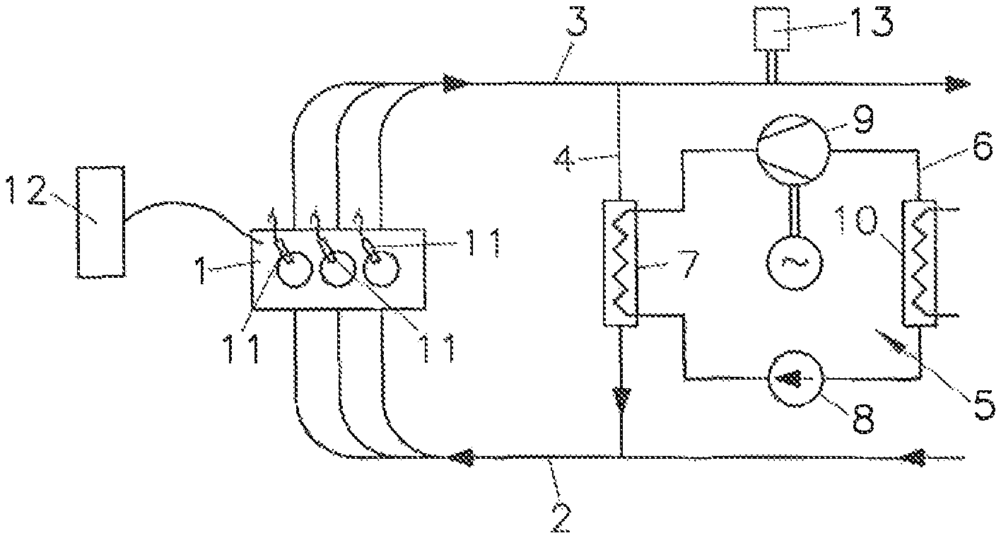
The drawing schematically shows an internal combustion engine 1 with an inlet branch 2 and an outlet branch 3, and an exhaust gas recirculation line 4 between the inlet branch 2 and the outlet branch 3. For recovering the exhaust heat, a heat-recovery system 5 is provided with a working medium circuit 6 for a working medium, having at least one EGR evaporator 7, a pump 8 and at least one expansion machine 9. Reference numeral 10 designates a condenser. Reference numeral 12 denotes the control unit of the internal combustion engine. Possible filters, catalytic converters, control elements and heat exchangers in the inlet branch 2 and outlet branch 3 are not shown.
DETAILED DESCRIPTION OF THE INVENTION
Fuel is injected via injectors 11 into the combustion chambers of the internal combustion engine 1.
In outlet branch 3, a sensor 13, e.g. a .lamda. sensor or a NOx sensor, is arranged, which is already installed by default for regulating the emissions in current conventional motor vehicles. If the detection of the leakages is activated, the oxygen concentration measured in the outlet branch 3 via the sensor 13 is compared with a predefined lower threshold value for a defined period of time.
If the oxygen concentration measured via the sensor 13 lies below this threshold, it is assumed that combustible working medium passes through a leakage in the EGR evaporator into the combustion chambers of the engine and the oxygen concentration in the exhaust gas is reduced there by thermal conversion (combustion). If the measured oxygen concentration is below the defined threshold value for longer than a predefined minimum time, a leakage in the EGR evaporator is detected. In the case of large leakages in the EGR evaporator, the oxygen concentration can also reach zero in extreme cases.
Leakage detection is enabled if the following conditions are met: The internal combustion engine 1 is in motor-braking mode, The sensor 13 is active, There is no fuel injection, for example, to raise the exhaust gas temperature and There is no error in the fuel injection system.
With the method described, it is possible to detect leakages in the EGR evaporator 7 of the heat-recovery system 5 with extremely little effort and without additional components or sensors.
* * * * *
D00000
D00001
XML
uspto.report is an independent third-party trademark research tool that is not affiliated, endorsed, or sponsored by the United States Patent and Trademark Office (USPTO) or any other governmental organization. The information provided by uspto.report is based on publicly available data at the time of writing and is intended for informational purposes only.
While we strive to provide accurate and up-to-date information, we do not guarantee the accuracy, completeness, reliability, or suitability of the information displayed on this site. The use of this site is at your own risk. Any reliance you place on such information is therefore strictly at your own risk.
All official trademark data, including owner information, should be verified by visiting the official USPTO website at www.uspto.gov. This site is not intended to replace professional legal advice and should not be used as a substitute for consulting with a legal professional who is knowledgeable about trademark law.