Vehicle seat with load sensor
Takayasu , et al.
U.S. patent number 10,677,638 [Application Number 16/157,379] was granted by the patent office on 2020-06-09 for vehicle seat with load sensor. This patent grant is currently assigned to TS TECH CO., LTD.. The grantee listed for this patent is TS TECH CO., LTD.. Invention is credited to Shigeru Endo, Shinya Ishima, Kenji Sato, Wataru Takayasu.


| United States Patent | 10,677,638 |
| Takayasu , et al. | June 9, 2020 |
Vehicle seat with load sensor
Abstract
A passenger's weight measurement device for a vehicle seat includes an upper rail provided on a lower rail that is fixable to a vehicle floor, the upper rail being movable in at least one of rear and front directions; a load sensor fixed onto the upper rail; and a frame provided on the load sensor and below the vehicle seat. In plan view, the load sensor protrudes from the frame in at least one of left and right directions.
| Inventors: | Takayasu; Wataru (Reynoldsburg, OH), Ishima; Shinya (Shioya-gun, JP), Endo; Shigeru (Shioya-gun, JP), Sato; Kenji (Sakura, JP) | ||||||||||
|---|---|---|---|---|---|---|---|---|---|---|---|
| Applicant: |
|
||||||||||
| Assignee: | TS TECH CO., LTD. (Asaka-shi,
JP) |
||||||||||
| Family ID: | 37899795 | ||||||||||
| Appl. No.: | 16/157,379 | ||||||||||
| Filed: | October 11, 2018 |
Prior Publication Data
| Document Identifier | Publication Date | |
|---|---|---|
| US 20190041254 A1 | Feb 7, 2019 | |
Related U.S. Patent Documents
| Application Number | Filing Date | Patent Number | Issue Date | ||
|---|---|---|---|---|---|
| 14842185 | Sep 1, 2015 | 10126159 | |||
| 13836773 | Oct 13, 2015 | 9156384 | |||
| 13137713 | Sep 24, 2013 | 8540047 | |||
| 12875594 | Oct 4, 2011 | 8028786 | |||
| 11992548 | Nov 23, 2010 | 7836997 | |||
| PCT/JP2006/319477 | Sep 29, 2006 | ||||
Foreign Application Priority Data
| Sep 30, 2005 [JP] | 2005-286881 | |||
| Current U.S. Class: | 1/1 |
| Current CPC Class: | B60R 21/01516 (20141001); G01G 19/08 (20130101); B60N 2/4263 (20130101); G01G 19/4142 (20130101); B60N 2/002 (20130101); B60R 21/0152 (20141001); B60N 2/06 (20130101); B60R 21/015 (20130101); B60N 2/90 (20180201); Y10S 411/946 (20130101); Y10S 177/09 (20130101) |
| Current International Class: | G01G 19/08 (20060101); B60N 2/06 (20060101); B60N 2/42 (20060101); B60R 21/015 (20060101); B60N 2/00 (20060101); B60N 2/90 (20180101); G01G 19/414 (20060101) |
References Cited [Referenced By]
U.S. Patent Documents
| 1679620 | August 1928 | Moore |
| 2252970 | August 1941 | Gedris |
| 2589570 | March 1952 | Phillips |
| 2589922 | March 1952 | Bowman |
| 4178037 | December 1979 | Pickles |
| 4182255 | January 1980 | Reid |
| 4209198 | June 1980 | Apple, Sr. |
| 4281443 | August 1981 | Threlfall |
| 4353565 | October 1982 | Smith et al. |
| 4509796 | April 1985 | Takagi |
| 4588225 | May 1986 | Sakamoto |
| 4597552 | July 1986 | Nishino |
| 4630864 | December 1986 | Toll |
| 4715651 | December 1987 | Wakamatsu |
| 5110177 | May 1992 | Akio |
| 5222399 | June 1993 | Kropp |
| 5240310 | August 1993 | Rink |
| 5286076 | February 1994 | DeVoss et al. |
| 5308148 | May 1994 | Peterson et al. |
| 5421124 | June 1995 | Zuccaro |
| 5478975 | December 1995 | Ford |
| 5492388 | February 1996 | Kawasaki |
| 5600104 | February 1997 | McCauley et al. |
| 5714695 | February 1998 | Bruns |
| 5775780 | July 1998 | Murphy et al. |
| 5921624 | July 1999 | Wu |
| 5942695 | August 1999 | Verma et al. |
| 5991676 | November 1999 | Podoloff et al. |
| 6010195 | January 2000 | Masters et al. |
| 6039344 | March 2000 | Mehney et al. |
| 6050635 | April 2000 | Pajon et al. |
| 6089478 | July 2000 | Truan et al. |
| 6145909 | November 2000 | Staley et al. |
| 6150619 | November 2000 | Borngasser |
| 6176543 | January 2001 | Nawata et al. |
| 6231076 | May 2001 | Blakesley et al. |
| 6356200 | March 2002 | Hamada et al. |
| 6367859 | April 2002 | Flory et al. |
| 6405987 | June 2002 | Andrigo et al. |
| 6499360 | December 2002 | Bruns |
| 6520023 | February 2003 | Kimura |
| 6555756 | April 2003 | Nakamura et al. |
| 6555765 | April 2003 | Paine |
| 6559392 | May 2003 | Haynes et al. |
| 6595570 | July 2003 | Susko |
| 6616239 | September 2003 | Guillot |
| 6637824 | October 2003 | Yokota |
| 6644903 | November 2003 | Arand |
| 6677539 | January 2004 | Miura et al. |
| 6682146 | January 2004 | Minai |
| 6684718 | February 2004 | Muraishi |
| 6695379 | February 2004 | Ishida |
| 6702376 | March 2004 | Shen |
| 6772985 | August 2004 | Lee |
| 6773069 | August 2004 | Kaneko et al. |
| 6774625 | August 2004 | Suzuki et al. |
| 6786691 | September 2004 | Alden, III |
| 6810984 | November 2004 | Sakai et al. |
| 6916997 | July 2005 | Thakur et al. |
| 6969809 | November 2005 | Rainey |
| 6981717 | January 2006 | Sakamoto et al. |
| 7036864 | May 2006 | Rehfuss et al. |
| 7038146 | May 2006 | Saito et al. |
| 7091426 | August 2006 | Nagai et al. |
| 7137665 | November 2006 | Osawa et al. |
| 7137669 | November 2006 | Nagayama |
| 7185867 | March 2007 | Hill et al. |
| 7189931 | March 2007 | Hida et al. |
| 7195261 | March 2007 | Yoshida et al. |
| 7210358 | May 2007 | Yamazaki |
| 7281766 | October 2007 | Fujita et al. |
| 7322605 | January 2008 | Ventura et al. |
| 7328627 | February 2008 | Kawabata et al. |
| 7373846 | May 2008 | Furukawa et al. |
| 7422291 | September 2008 | Nagayama |
| 7435918 | October 2008 | Becker et al. |
| 7438350 | October 2008 | Peterson et al. |
| 7455343 | November 2008 | Endo et al. |
| 7488026 | February 2009 | Jovicevic |
| 7510161 | March 2009 | Fischer et al. |
| 7520175 | April 2009 | Matsukawa et al. |
| 7566086 | July 2009 | Gray et al. |
| 7604213 | October 2009 | Choi et al. |
| 7614680 | November 2009 | Endo et al. |
| 7729122 | June 2010 | Wong |
| 7731281 | June 2010 | Kurita et al. |
| 7762150 | July 2010 | Kawabata et al. |
| 7793557 | September 2010 | Endo et al. |
| 7823951 | November 2010 | Endo et al. |
| 7836997 | November 2010 | Takayasu et al. |
| 7870927 | January 2011 | Endo et al. |
| 7878570 | February 2011 | Endo et al. |
| 8002071 | August 2011 | Endo et al. |
| 8011715 | September 2011 | Endo et al. |
| 8028786 | October 2011 | Takayasu et al. |
| 8051941 | November 2011 | Takayasu et al. |
| 8136619 | March 2012 | Hwang et al. |
| 8136620 | March 2012 | Hwang et al. |
| RE43989 | February 2013 | Furukawa et al. |
| 8371655 | February 2013 | Nonomiya |
| 8540047 | September 2013 | Takayasu et al. |
| 8548687 | October 2013 | Jefferies et al. |
| 2003/0168895 | September 2003 | Sakai et al. |
| 2004/0100388 | May 2004 | Yoshida et al. |
| 2004/0160113 | August 2004 | Rehfuss et al. |
| 2005/0061643 | March 2005 | Rainey |
| 2005/0099041 | May 2005 | Becker et al. |
| 2005/0109909 | May 2005 | Osawa et al. |
| 2005/0284238 | December 2005 | Wilkie et al. |
| 2005/0284668 | December 2005 | Hida et al. |
| 2005/0284669 | December 2005 | DiPaola et al. |
| 2006/0010984 | January 2006 | Yamazaki |
| 2006/0048582 | March 2006 | Furukawa et al. |
| 2007/0012487 | January 2007 | Becker et al. |
| 2007/0028702 | February 2007 | Sakamoto et al. |
| 2007/0057527 | March 2007 | Endo et al. |
| 2008/0036251 | February 2008 | Endo et al. |
| 2008/0079296 | April 2008 | Endo et al. |
| 2008/0084086 | April 2008 | Endo et al. |
| 2009/0079239 | March 2009 | Endo et al. |
| 2009/0139774 | June 2009 | Takayasu et al. |
| 2009/0139775 | June 2009 | Takayasu et al. |
| 2009/0294185 | December 2009 | Bruzzone et al. |
| 2009/0301793 | December 2009 | Endo et al. |
| 2009/0301794 | December 2009 | Endo et al. |
| 2010/0044117 | February 2010 | Takayasu et al. |
| 2010/0282522 | November 2010 | Endo et al. |
| 2011/0006580 | January 2011 | Ishimoto et al. |
| 2011/0018301 | January 2011 | Endo et al. |
| 2011/0018302 | January 2011 | Endo et al. |
| 2011/0073381 | March 2011 | Endo et al. |
| 2011/0094803 | April 2011 | Takayasu et al. |
| 2011/0108330 | May 2011 | Endo et al. |
| 2011/0147096 | June 2011 | Endo et al. |
| 2011/0303469 | December 2011 | Saito et al. |
| 103 15 400 | Oct 2004 | DE | |||
| 2 415 787 | Jan 2006 | GB | |||
| S63-26466 | Feb 1988 | JP | |||
| H05-43031 | Jun 1993 | JP | |||
| H08-164039 | Jun 1996 | JP | |||
| H09-207638 | Aug 1997 | JP | |||
| H10-297334 | Nov 1998 | JP | |||
| H11-108746 | Apr 1999 | JP | |||
| H11-304579 | Nov 1999 | JP | |||
| 2000-280813 | Oct 2000 | JP | |||
| 2001-030819 | Feb 2001 | JP | |||
| 2001-050329 | Feb 2001 | JP | |||
| 2001-158269 | Jun 2001 | JP | |||
| 2003-011709 | Jan 2003 | JP | |||
| 2003-166872 | Jun 2003 | JP | |||
| 2003-237535 | Aug 2003 | JP | |||
| 2003-287458 | Oct 2003 | JP | |||
| 2004-210167 | Jul 2004 | JP | |||
| 2004-268620 | Sep 2004 | JP | |||
| 2004-306849 | Nov 2004 | JP | |||
| 2005-049272 | Feb 2005 | JP | |||
| 2008-296657 | Dec 2008 | JP | |||
| 2005/012849 | Feb 2005 | WO | |||
Other References
|
Oct. 9, 2013 Office Action issued in U.S. Appl. No. 12/588,922. cited by applicant . Oct. 22, 2013 Office Action issued in U.S. Appl. No. 13/010,429. cited by applicant . Aug. 23, 2013 Office Action issued in U.S. Appl. No. 13/242,780. cited by applicant . Jun. 13, 2013 Office Action issued in U.S. Appl. No. 13/175,565. cited by applicant . Apr. 3, 2013 Office Action in U.S. Appl. No. 12/588,922. cited by applicant . Sep. 22, 2014 Office Action issued in U.S. Appl. No. 13/840,930. cited by applicant . Jan. 13, 2011 Office Action issued in U.S. Appl. No. 11/992,418. cited by applicant . Jan. 18, 2011 Notice of Allowance issued in U.S. Appl. No. 12/536,124. cited by applicant . Dec. 6, 2011 Office Action issued in U.S. Appl. No. 13/039,458. cited by applicant . Nov. 29, 2011 Office Action issued in Japanese Application No. 2007-537702 (with translation). cited by applicant . Nov. 30, 2011 Office Action issued in Chinese Application No. 201010552150.5 (with translation). cited by applicant . Jan. 12, 2012 Office Action issued in European Application No. 10007613.2. cited by applicant . Sep. 22, 2014 Office Action issued in U.S. Appl. No. 13/836,773. cited by applicant . Aug. 24, 2017 Office Action Issued in U.S. Appl. No. 14/842,185. cited by applicant . Jan. 23, 2018 Office Action issued in U.S. Appl. No. 14/842,185. cited by applicant . Jul. 13, 2018 Notice of Allowance issued in U.S. Appl. No. 14/842,185. cited by applicant . Oct. 10, 2018 Notice of Allowability issued in U.S. Appl. No. 14/842,185. cited by applicant . Jan. 28, 2015 Office Action issued in U.S. Appl. No. 13/840,865. cited by applicant . Jan. 23, 2015 Office Action issued in U.S. Appl. No. 13/840,930. cited by applicant . European Search Report for European Application No. 10007613.2 dated Oct. 9, 2010. cited by applicant . Feb. 3, 2015 Office Action issued in U.S. Appl. No. 13/841,207. cited by applicant . Jan. 26, 2015 Office Action issued in U.S. Appl. No. 13/841,156. cited by applicant . "Radius" from eFunda Design Standards website, Copyright 2010 by eFunda, Inc. (http://www.efunda.com/designstandards/plastic_design/radius.cfm). cited by applicant . "What is eFunda" from eFunda Design Standards website, Copyright 2010 by eFunda, Inc. (http://www.efunda.com/about/about.cfm). cited by applicant . Aug. 3, 2010 English-language translation of Japanese Office Action in Application No. 2004-223456. cited by applicant . Office Action for U.S. Appl. No. 12/536,075, dated Apr. 7, 2010. cited by applicant . Office Action for U.S. Appl. No. 12/536,075, dated Oct. 15, 2010. cited by applicant . Office Action for U.S. Appl. No. 12/536,124, dated Jul. 1, 2010. cited by applicant . Notice of Allowance for U.S. Appl. No. 12/536,075, dated Nov. 8, 2010. cited by applicant . Office Action for U.S. Appl. No. 12/536,151, dated Aug. 10, 2010. cited by applicant . Office Action for U.S. Appl. No. 11/992,418, dated Jul. 2, 2009. cited by applicant . Notice of Allowance for U.S. Appl. No. 11/992,418, dated Feb. 18, 2010. cited by applicant . Office Action for U.S. Appl. No. 11/992,418, dated Jun. 3, 2010. cited by applicant . Office Action for U.S. Appl. No. 12/588,922, dated Sep. 29, 2010. cited by applicant . Jan. 8, 2014 Office Action issued in U.S. Appl. No. 13/175,565. cited by applicant . Nov. 13, 2013 Office Action issued in U.S. Appl. No. 12/985,932. cited by applicant . Dec. 13, 2013 Office Action issued in U.S. Appl. No. 13/601,330. cited by applicant . May 14, 2014 Office Action issued in U.S. Appl. No. 13/010,429. cited by applicant . Sep. 25, 2014 Office Action issued in U.S. Appl. No. 13/841,156. cited by applicant . Sep. 25, 2014 Office Action issued in U.S. Appl. No. 13/841,207. cited by applicant . Jun. 3, 2015 Notice of Allowance issued in U.S. Appl. No. 13/836,773. cited by applicant . May 24, 2012 Second Office Action issued in Chinese Application No. 201010552150.5 with English-language translation. cited by applicant . Aug. 2, 2012 Office Action issued in U.S. Appl. No. 13/137,713. cited by applicant . Apr. 9, 2012 Office Action issued in U.S. Appl. No. 13/105,483. cited by applicant . Dec. 15, 2011 Search Report issued in European Application No. 11181454.7. cited by applicant . Jan. 31, 2011 Office Action issued in U.S. Appl. No. 12/536,151. cited by applicant . Sep. 9, 2011 Notice of Allowance issued in U.S. Appl. No. 12/961,758. cited by applicant . Sep. 15, 2011 Office Action issued in U.S. Appl. No. 12/985,932. cited by applicant . Nov. 16, 2011 Office Action issued in U.S. Appl. No. 13/010,429. cited by applicant . U.S. Appl. No. 13/242,780, filed Sep. 23, 2011. cited by applicant . Sep. 24, 2014 Office Action issued in U.S. Appl. No. 13/840,865. cited by applicant . Feb. 11, 2013 Office Action issued in U.S. Appl. No. 13/175,565. cited by applicant . Jan. 28, 2013 Final Office Action issued in U.S. Appl. No. 13/137,713. cited by applicant . Office Action for U.S. Appl. No. 12/588,922, dated Mar. 8, 2011. cited by applicant . Notice of Allowance for U.S. Appl. No. 12/536,151, dated Mar. 25, 2011. cited by applicant . Office Action for U.S. Appl. No. 12/961,758, dated Mar. 28, 2011. cited by applicant . Office Action for U.S. Appl. No. 13/010,429, dated May 2, 2011. cited by applicant. |
Primary Examiner: Gibson; Randy W
Attorney, Agent or Firm: Oliff PLC
Parent Case Text
This is Continuation of U.S. application Ser. No. 14/842,185 filed on Sep. 1, 2015, which is a continuation of U.S. application Ser. No. 13/836,773 filed Mar. 15, 2013, which is a Continuation of U.S. application Ser. No. 13/137,713 filed Sep. 7, 2011, which is a Continuation of U.S. application Ser. No. 12/875,594 filed Sep. 3, 2010, which is a Continuation of U.S. application Ser. No. 11/992,548 filed Mar. 25, 2008, which is a National Stage of International Application No. PCT/JP2006/319477 filed Sep. 29, 2006, which in turn claims the benefit of priority from Japanese Application No. 2005-286881 filed Sep. 30, 2005. The disclosures of the prior applications are hereby incorporated by reference herein in their entirety.
Claims
What is claimed is:
1. A vehicle seat, comprising: left and right rails, each comprising (i) a lower rail fixable to a vehicle floor and (ii) an upper rail provided on the lower rail so as to be movable in forward and rear directions; a load sensor fixed onto at least one of the upper rails; a frame that is provided on the load sensor and that consists of (i) left and right longitudinal members that extend in the forward and rear directions, (ii) a cross pipe bridging rear portions of the longitudinal members, and (iii) a pan frame bridging front portions of the longitudinal members; a seat spring that extends forward from the cross pipe and that comprises (i) a link fixed to the cross pipe and (ii) spring wires hooked to the link; and a lower bracket bridging the rails, wherein the load sensor comprises a connector that is forward of the link and is directed forward, and wherein forward and rear widths of the lower bracket (i) are larger than a width of a center of the lower bracket in the forward and rear directions and (ii) are larger than a length of the connector of the load sensor in the forward and rear directions.
2. The vehicle seat according to claim 1, wherein: the link of the seat spring comprises a single link that extends in left and right directions; the spring wires extend in the forward and rear directions; and a width of the link in the left and right directions is larger than a width of the connector of the load sensor in the left and right directions.
3. The vehicle seat according to claim 1, wherein: at least one of the longitudinal members comprises a bead that expands outward; and a length of the bead in the forward and rear directions is larger than a width of the connector of the load sensor in left and right directions.
4. The vehicle seat according to claim 3, wherein the cross pipe penetrates the longitudinal members rearward of the load sensor and the bead.
5. The vehicle seat according to claim 1, further comprising a forward said load sensor and a rear said load sensor, wherein at least one of the longitudinal members comprises: two beads that expand outwardly around the forward load sensor and the rear load sensor, respectively; and a hole between the two beads.
6. The vehicle seat according to claim 1, wherein: each of the longitudinal members comprises: a wide portion that is wider than a center of the longitudinal member in up and down directions, and a bead that expands outward at the wide portion; and the cross pipe penetrates the longitudinal members at the wide portion.
7. The vehicle seat according to claim 1 wherein: the lower bracket comprises an oblique portion along a rear edge of the lower bracket, the oblique portion extending obliquely such that an end of the lower bracket is rearward of a center of the lower bracket; and an end of the lower bracket is forward of the connector of the load sensor.
8. The vehicle seat according to claim 1, further comprising a forward said load sensor and a rear said load sensor, wherein: the lower bracket is closer to the forward load sensor than to the rear load sensor; and the lower bracket comprises holes that align in left and right directions.
9. The vehicle seat according to claim 1, wherein: at least one of the longitudinal members comprises a bead; and the cross pipe penetrates a portion of the at least one longitudinal member other than the bead.
Description
TECHNICAL FIELD
The present invention relates to a passenger's weight measurement device for a vehicle seat, which measures a weight of a passenger seated on the vehicle seat, and to an attachment structure for attaching a load sensor to the passenger's weight measurement device.
BACKGROUND ART
In recent years, in some cases, operations of various safety devices such as a seat belt and an air bag have been controlled in accordance with a weight of a passenger seated on a vehicle seat for the purpose of enhancing performance of the safety devices. In a conventional passenger's weight measurement device that measures the weight of the seated passenger, a load sensor is interposed between a vehicle floor and the vehicle seat (for example, refer to Patent Document 1 and Patent Document 2).
Patent Document 1: JP A H8-164039
Patent Document 2: JP A H9-207638
DISCLOSURE OF THE INVENTION
Problems to be Solved by the Invention
However, there is a dimension error or an assembling position error when the passenger's weight measurement device is assembled, when the vehicle seat is fixed to the passenger's weight measurement device or when the passenger's weight measurement device is fixed to the vehicle floor, or the like. Accordingly, it has been difficult to assemble the passenger's weight measurement device.
In this connection, it is an object of the present invention to provide a passenger's weight measurement device for a vehicle seat, which is more easily assembled, and to provide an attachment structure for a load sensor.
Means for Solving the Problems
In order to solve the above-described problem, a passenger's weight measurement device for a vehicle seat according to the present invention comprises: an upper rail provided on a lower rail fixed to a vehicle floor so as to be movable in a rear and front direction; a load sensor fixed onto the upper rail; and a frame provided on the load sensor and below the vehicle seat, wherein a rod is extended from the load sensor, the rod sequentially penetrates the frame and a spring holder and is inserted into a coil spring, a nut is screwed to the rod from above the spring holder, and the coil spring is sandwiched between the spring holder and the frame and is compressed by tightening the nut to the spring holder.
An attachment structure for a load sensor according to the present invention is an attachment structure for attaching the load sensor to a frame provided below a vehicle seat, wherein a rod is extended from the load sensor, the rod sequentially penetrates the frame and a spring holder and is inserted into a coil spring, a nut is screwed to the rod from above the spring holder, and the coil spring is sandwiched between the spring holder and the frame and is compressed by tightening the nut to the spring holder.
In the present invention, preferably, the spring holder includes a cup portion in which a through hole through which the rod penetrates is formed in a bottom, and a flange formed on an outer circumference of the cup portion, and the cup portion is inserted through the coil spring, the nut is inserted into the cup portion to tighten the bottom of the cup portion, and the coil spring is sandwiched between the flange and the flame.
In the present invention, preferably, a collar through which the rod is inserted penetrates the frame, the spring holder is sandwiched between the collar and the nut, and the coil spring and the collar are sandwiched between the nut and the load sensor.
In accordance with the present invention, the nut is screwed to the rod from above the spring holder, and the coil spring is sandwiched between the spring holder and the frame by tightening the nut. Accordingly, the frame can be shifted in the vertical direction with respect to the load sensor.
Effect of the Invention
In accordance with the present invention, the frame can be shifted in the vertical direction with respect to the load sensor. Accordingly, even if the lower rail, the upper rail, the frame and the like are distorted during the assembling or the like, an initial load generated by such distortions can be prevented from being applied to the load sensor.
Moreover, the coil spring is sandwiched between the frame and the spring holder in a state of being compressed by tightening the nut. Accordingly, the load sensor is fixed to the frame more stably and appropriately. Therefore, it becomes easier to assemble the passenger's weight measurement device.
Furthermore, the load is stably applied from the coil spring to the nut owing to elastic deformation of the coil spring, which is caused by tightening the nut.
BRIEF DESCRIPTION OF THE DRAWINGS
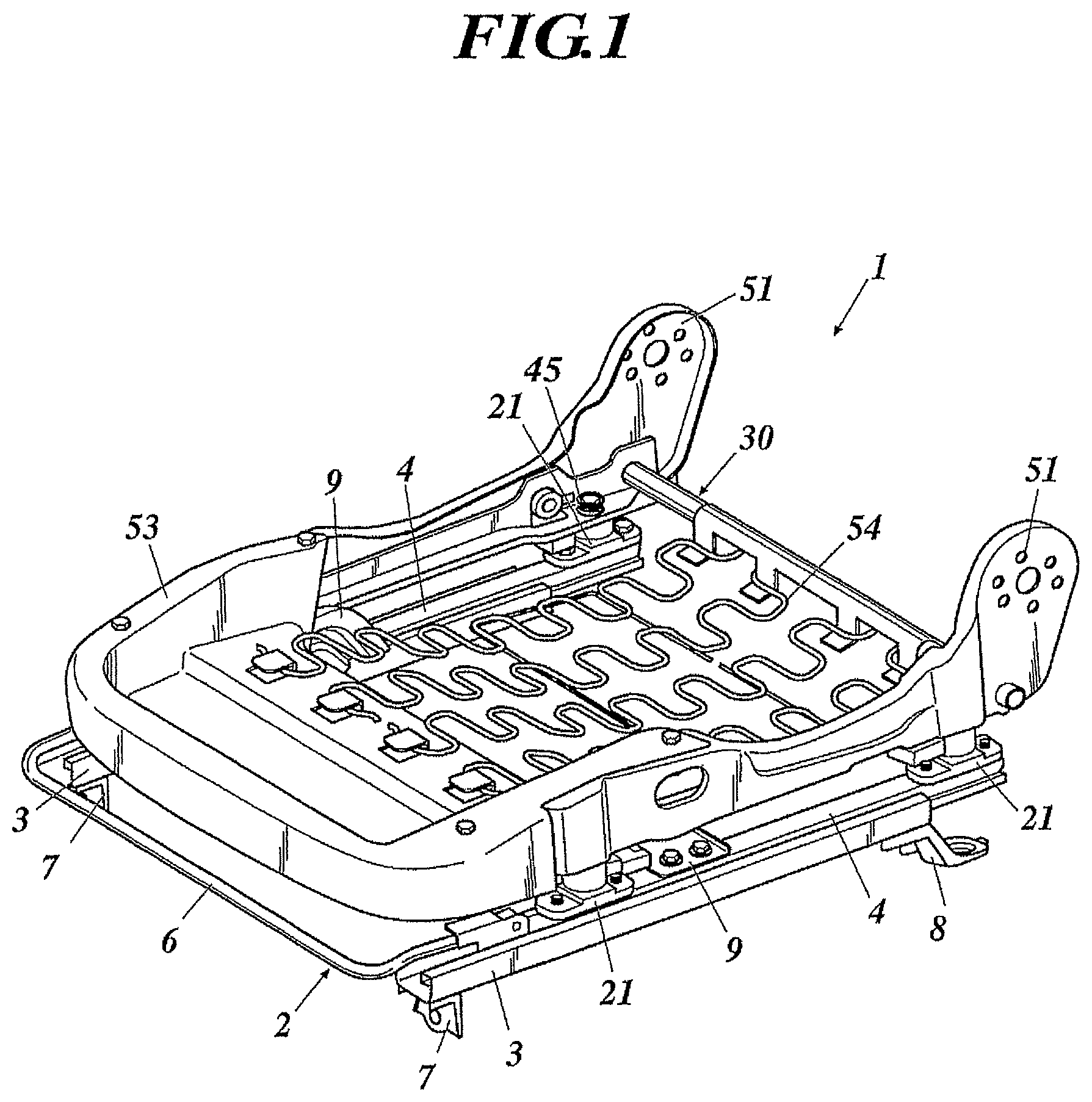
FIG. 1 This is a perspective diagram of a passenger's weight measurement device 1 for a vehicle seat.
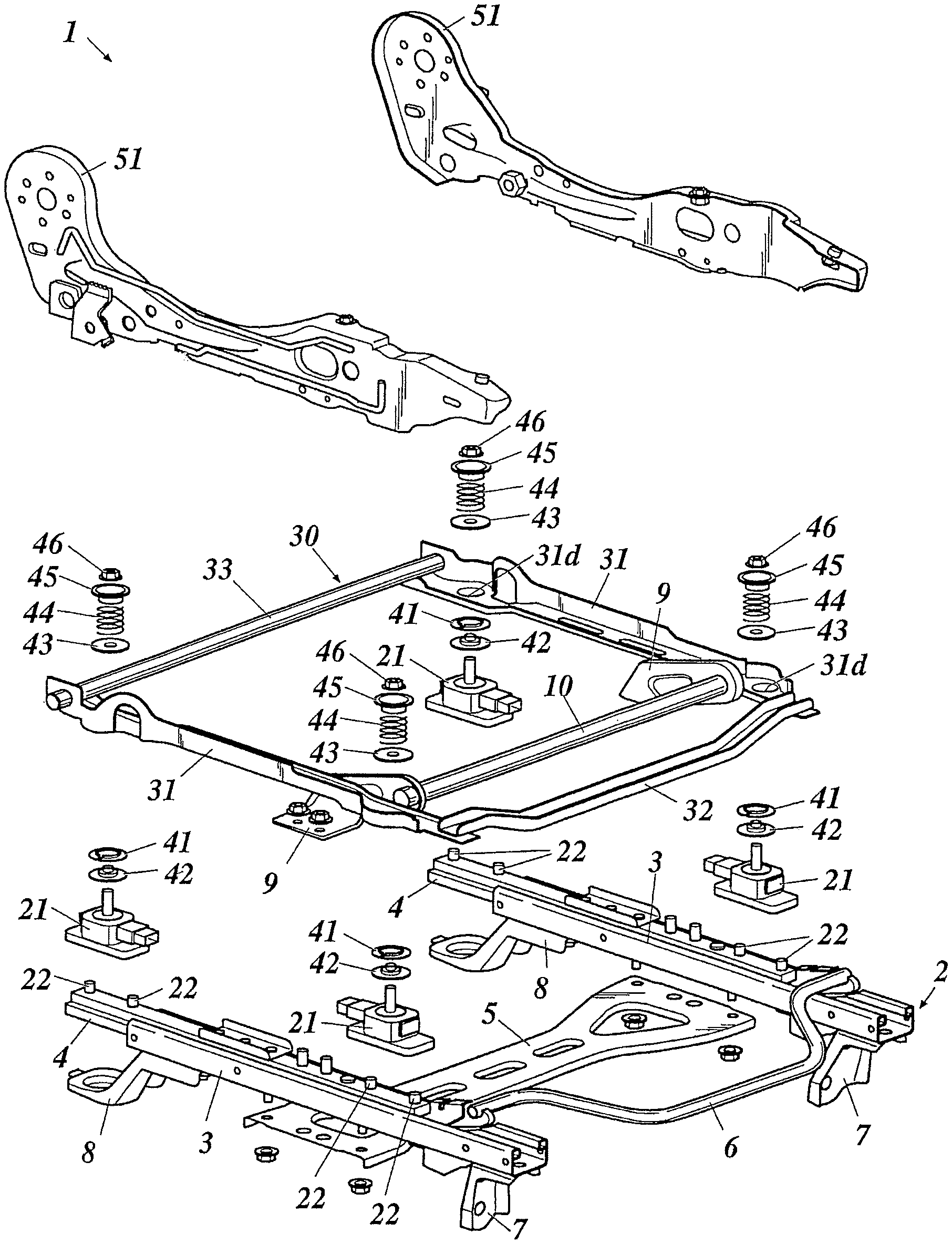
FIG. 2 This is an exploded perspective diagram of the passenger's weight measurement device 1.
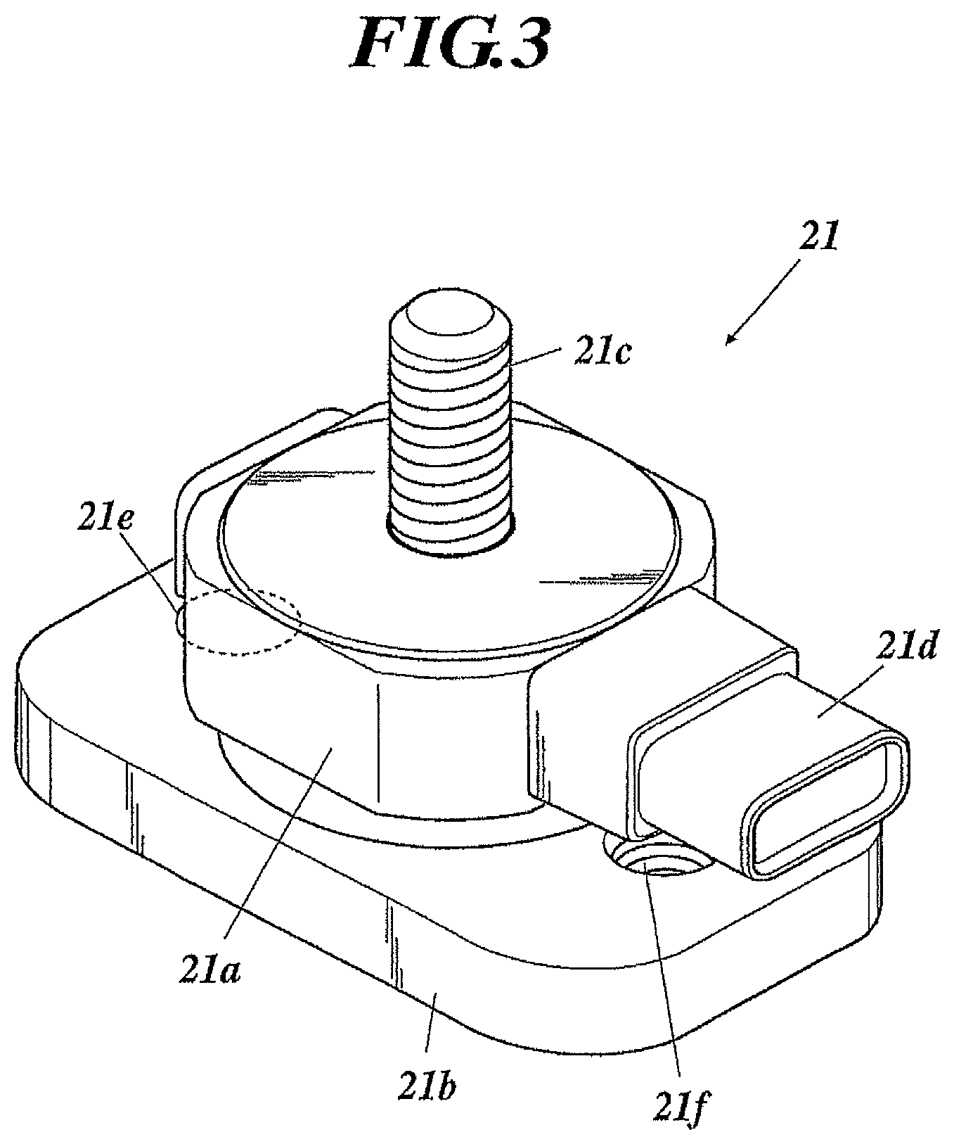
FIG. 3 This is a perspective diagram of a load sensor 21.
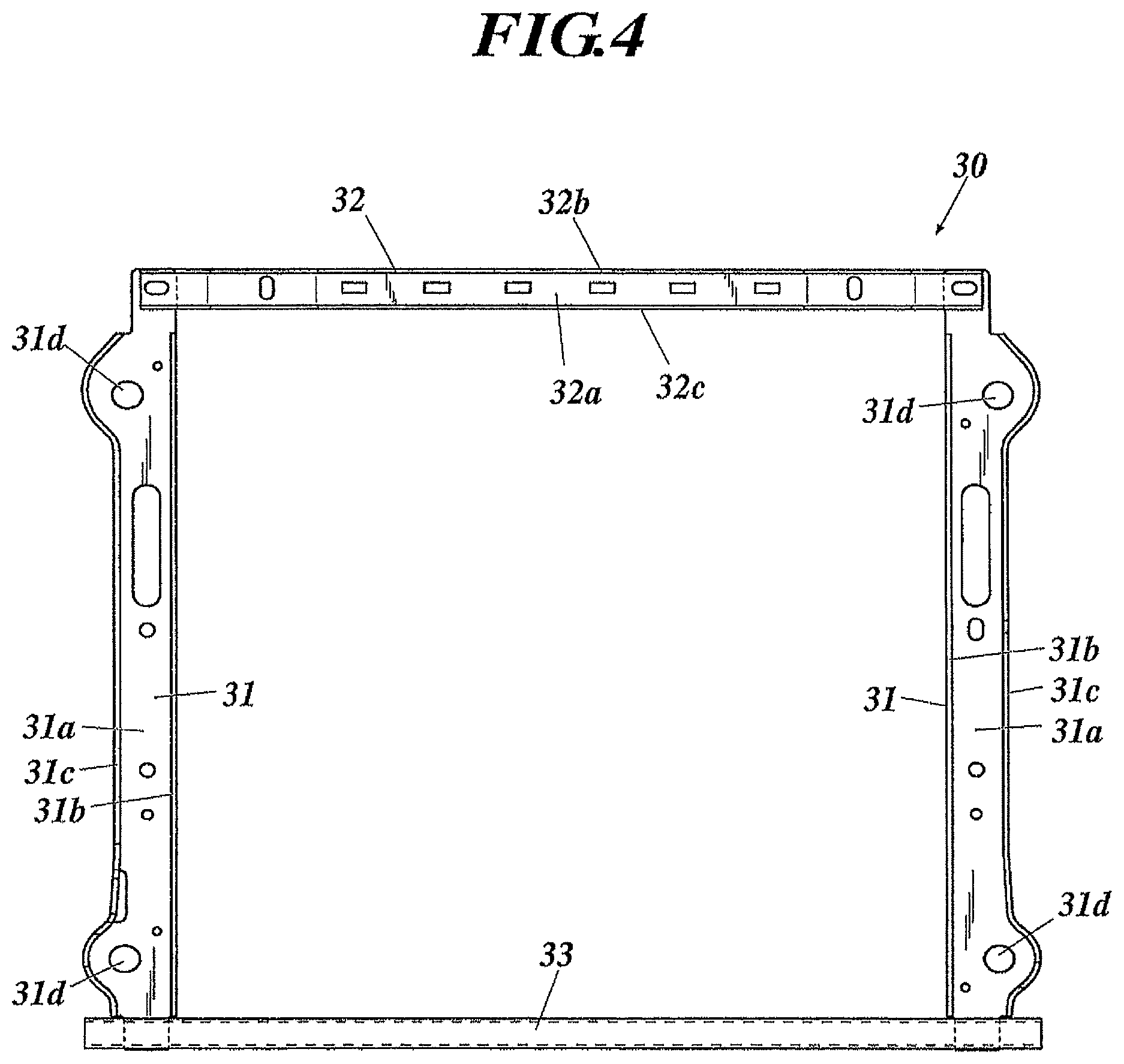
FIG. 4 This is a plan diagram of a rectangular frame 30.
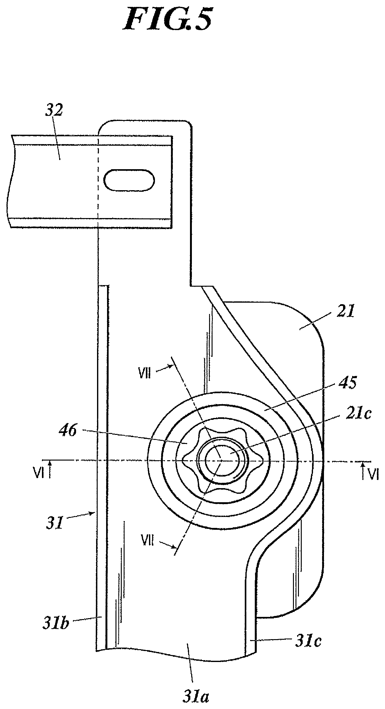
FIG. 5 This is a plan diagram of a right front portion of the rectangular frame 30.
FIG. 6 This is a cross-sectional diagram showing a cross section along a section line VI-VI of FIG. 5.
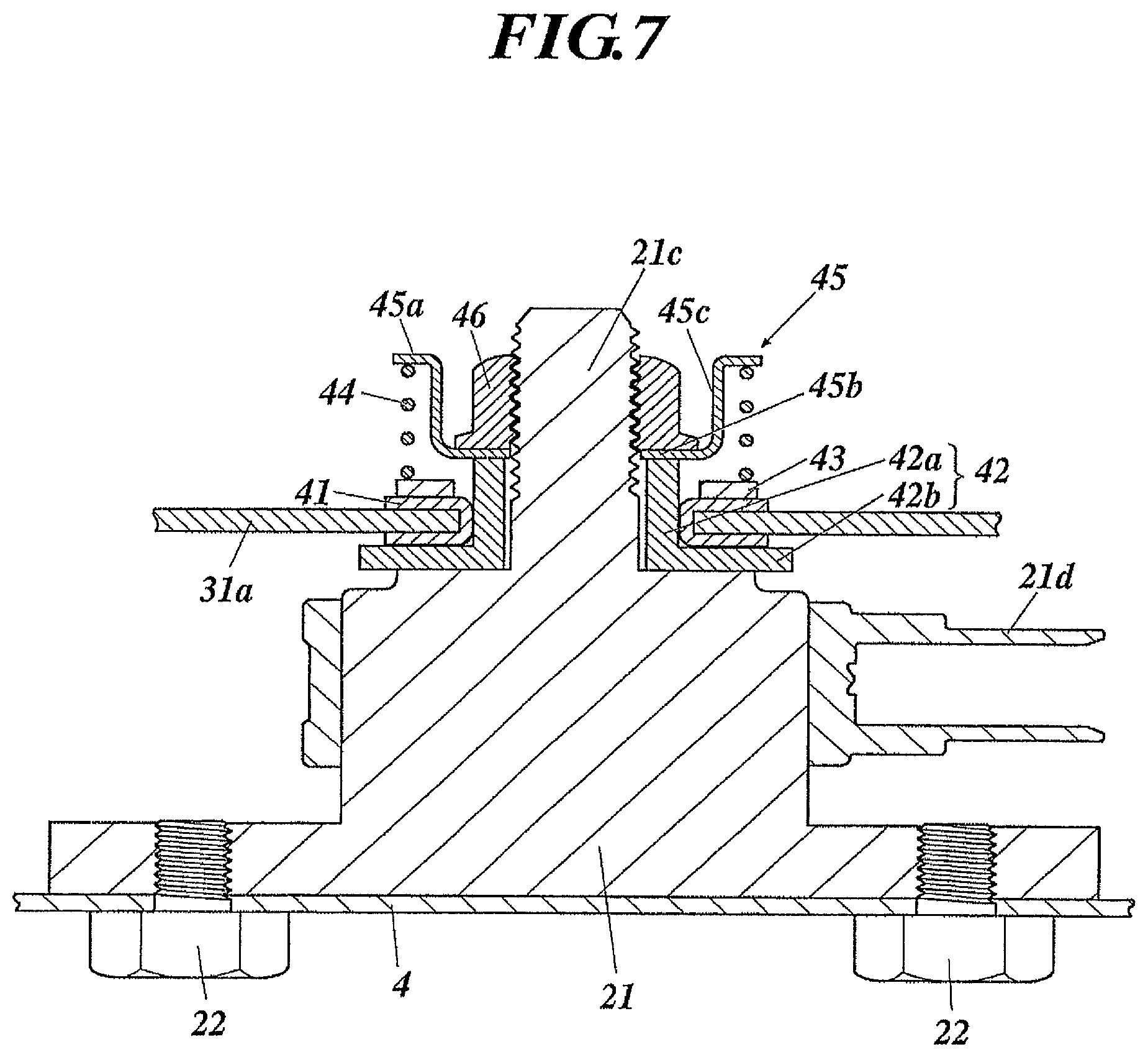
FIG. 7 This is a cross-sectional diagram showing a cross section along a section line VII-VII of FIG. 5.
FIG. 8 This is a cross-sectional diagram showing a modification example of FIG. 6, and showing a cross section along the section line VI-VI in a similar way to FIG. 6.
FIG. 9 This is a cross-sectional diagram showing a modification example of FIG. 7, and showing a cross section along the section line VII-VII in a similar way to FIG. 7.
BEST MODE FOR CARRYING OUT THE INVENTION
A best mode for carrying out the present invention will be described below by using the drawings. On embodiments to be described below, a variety of technically preferable limitations are imposed in order to carry out the present invention; however, the scope of the invention is not limited to the following embodiments and illustrated examples.
FIG. 1 is a perspective diagram of a passenger's weight measurement device 1 for a vehicle seat, and FIG. 2 is an exploded perspective diagram of the passenger's weight measurement device 1.
As shown in FIG. 1 and FIG. 2, a slide adjuster 2 for adjusting a back-and-forth position of the vehicle seat is attached onto a floor of a passenger's room. The slide adjuster 2 includes a left and right pair of lower rails 3 provided in parallel to each other, a left and right pair of upper rails 4 engaged with the lower rails 3 so as to be capable of sliding on the respective lower rails 3 in a rear and front direction with respect to the lower rails 3, a lower bracket 5 fixed to lower surfaces of the lower rails 3 by bolt/nut coupling or rivet coupling and bridged between the left and right lower rails 3, a lock mechanism 6 for locking the upper rails 4 to the lower rails 3 and for releasing the locking, brackets 7 attached onto front end portions of the lower surfaces of the respective lower rails 3, and brackets 8 attached onto rear end portions of the lower surfaces of the respective lower rails 3. These brackets 7 and 8 are attached onto the vehicle floor, and the lower rails 3 are fixed to the vehicle floor.
Brackets 9 are fixed to middle positions of upper surfaces of the respective upper rails 4 in a rear and front direction by the bolt/nut coupling or the rivet coupling. The brackets 9 are provided in a state of being erected with respect to upper surfaces of the upper rails 4. A right end portion of a submarine pipe 10 is welded to the brackets 9, and the submarine pipe 10 is bridged between the two left and right brackets 9.
A load sensor 21 is mounted on a front end portion of the upper surface of the right upper rail 4, and another load sensor 21 is mounted on a rear end portion thereof. Also on the upper surface of the left upper rail 4, load sensors 21 are mounted on a front end portion and rear end portion thereof, respectively. When viewed from the above, these four load sensors 21 are arranged so as to be apexes of a square or a rectangle.
FIG. 3 is a perspective diagram of the load sensor 21. All of the load sensors 21 are provided in a similar way. As shown in FIG. 3, the load sensor 21 includes a columnar sensing portion 21a that senses a load, a plate-like flange portion 21b extending horizontally in a rear and front direction from a lower end of the sensing portion 21a, a rod 21c extending upward from an upper end of the sensing portion 21a, and a connector 21d extending from the sensing portion 21a so as to be parallel to the flange portion 21b. The rod 21c is formed into a male screw shape. Female screw-shaped circular holes 21e and 21f which penetrate the flange portion 21b in the vertical direction are formed in front and rear portions of the flange portion 21b, respectively. The sensing portion 21a incorporates a strain gauge therein, and the load is converted into an electric signal by the strain gauge.
As shown in FIG. 2, the load sensor 21 is fixed to the right upper rail 4. Specifically, a lower surface of the flange portion 21b abuts on the upper surface of the upper rail 4, and two bolts 22 inserted through the upper rail 4 upward from below are screwed to the circular holes 21e and 21f, respectively. Therefore, the load sensor 21 is fixed. Note that the load sensor 21 may be fixed to the upper rail 4 by fastening nuts to the bolts 22 on the flange portion 21b without forming any screw threads in the circular holes 21e and 21f.
Any load sensor 21 is fixed to the upper rails 4 as described above. However, with regard to the two load sensors 21 fixed to the rear portions thereof, the connectors 21d are directed forward, and with regard to the two load sensors 21 fixed to the front portions thereof, the connectors 21d are directed backward.
As shown in FIG. 1 and FIG. 2, the frame 30 having a rectangular frame shape is mounted on these four load sensors 21. FIG. 4 is a top diagram of the rectangular frame 30. As shown in FIG. 4, the rectangular frame 30 is composed of a left and right pair of beams 31, a front beam 32, and a rear cross pipe 33.
Either of the beams 31 is a metal member having a U-shaped cross section, and has a web 31a, an inner flange 31b, and an outer flange 31c. Attachment holes 31d are formed in a front portion and a rear portion of the web 31a, respectively.
The front beam 32 is a metal member having a U-shaped cross section, and has a web 32a, a front flange 32b, and a rear flange 32c. The front beam 32 is bridged between front end portions of the left and right beams 31, and is welded to these beams 31.
The cross pipe 33 is bridged between rear end portions of the left and right beams 31, and is welded to these beams 31.
The rods 21c of the load sensors 21 are inserted into the respective attachment holes 21d upward from below, and nuts 46 are screwed to the rods 21c. Therefore, the load sensors 21 are attached onto a right front portion, a right rear portion, a left front portion and a left rear portion of the rectangular frame 30, respectively. Referring to FIG. 5 to FIG. 7, an attachment structure for attaching the right front load sensor 21 onto the right front portion of the rectangular frame 30 will be described. FIG. 5 is a plan diagram of the right front portion of the rectangular frame 30, FIG. 6 is a cross-sectional diagram showing a cross section along a line VI-VI, and FIG. 7 is a cross-sectional diagram showing a cross section along a line VII-VII. As shown in FIG. 5 to FIG. 7, an annular bush 41 is fitted to an edge of the right front attachment hole 31d, and grease is applied on the bush 41. The bush 41 is an oilless bush formed by impregnating oil into a metal material, or is made of synthetic resin. The bush 41 may be one made of other materials. Moreover, a stepped collar 42 composed of a cylindrical portion 42a and an annular plate-like flange portion 42b formed on one end surface of the cylindrical portion 42a is inserted through the attachment hole 31d in an inside of the bush 41. Here, the cylindrical portion 42a is inserted through the attachment hole 31d upward from below, and the flange portion 42b engages with a lower surface of the web 31a via the bush 41. Therefore, the stepped collar 42 is not pulled out upward. Moreover, the cylindrical portion 42a protrudes from an upper surface of the web 31a, and an upper end surface of the cylindrical portion 42a is located at a higher position than the upper surface of the web 31a. Here, the cylindrical portion 42a is fitted to the bush 41, and there is no gap between the cylindrical portion 42a and the bush 41.
The rod 21c of the load sensor 21 is inserted through the stepped collar 42 upward from below. An inner diameter of the stepped collar 42 is designed to be slightly larger than a diameter of the rod 21c, and by such designing, a dimension error and an attachment position error are solved.
The nut 46 is screwed to the rod 21c. A plain washer 43, a coil spring 44 and a spring holder 45 are interposed between the upper surface of the web 31a of the beam 31 and the nut 46. The rod 21c and the cylindrical portion 42a of the stepped collar 42 are inserted through the plain washer 43, and the plain washer 43 is set in a state of being mounted on the web 31a, and particularly, on the bush 41. Furthermore, the rod 21c is inserted through the coil spring 44, and the coil spring 44 is set in a state of being mounted on the plain washer 43. A portion of the coil spring 44, which is brought into contact with the plain washer 43, is formed to be flat.
The spring holder 45 includes a cup portion 45c in which a through hole is formed in a bottom 45b, and an annular flange 45a formed on an outer circumferential surface in an opening of the cup portion 45c. Then, the rod 21c penetrates through the through hole of the bottom 45b of the cup portion 45c, the bottom 45b of the cup portion 45c is set in a state of being mounted on an end surface of the stepped collar 42, and the cup portion 45c is inserted into the coil spring 44. Moreover, the coil spring 44 and the plain washer 43 are set in a state of being sandwiched between the flange 45a of the spring holder 45 and the web 31a.
The nut 46 is screwed to the rod 21c in a state of being inserted into the cup portion 45c, and by tightening the nut 46, the bottom 45b of the cup portion 45c is sandwiched between the nut 46 and the upper end surface of the cylindrical portion 42a, and the coil spring 44 and the plain washer 43 are sandwiched between the flange 45a and the web 31a of the beam 31. Moreover, since the coil spring 44 is compressed by tightening the nut 46, the load is applied to the nut 46, and accordingly, the nut 46 is prevented from being loosened. Note that the coil spring 44 is set in a state of being mounted on the web 31a of the beam 31 via the plain washer 43. However, the coil spring 44 may be set in a state of being directly mounted on the web 31a of the beam 31, and the coil spring 44 may be sandwiched between the flange 45a and the web 31a.
Like the right front load sensor 21, the left front, left rear and right rear load sensors 21 are attached onto the left front, left rear and right rear attachment holes 31d, respectively. In a state where the four load sensors 21 are attached onto the rectangular frame 30, the submarine pipe 10 is located behind the front beam 32.
As shown in FIG. 1 and FIG. 2, side frames 51 are welded to the outer flanges 31c of the left and right beams 31, respectively. These side frames 51 are parts of a bottom frame of the vehicle seat.
From above, front portions of the side frames 51 are covered with a pan frame 53, and the side frames 51 and the pan frame 53 are fixed to each other by the bolt/nut coupling or the rivet coupling. A seat spring 54 is bridged between the cross pipe 33 and the pan frame 53, a cushion is mounted on the pan frame 53 and the seat spring 54, and the cushion, the pan frame 53 and the side frames 51 are entirely covered with a cover.
A backrest frame is coupled to rear ends of the side frames 51, and is capable of rising and falling by a reclining mechanism. Note that the backrest frame and the cushion are not shown in order to make it easy to view the drawings.
In the passenger's weight measurement device 1 configured as described above, when a passenger is seated on a seat bottom, a weight of the passenger is applied to the four load sensors 21 through the rectangular frame 30, and is converted into electric signals by these load sensors 21.
Here, the load sensors 21 are attached between the upper rails 4 and the rectangular frame 30, and the load sensors 21 move in a rear and front direction integrally with the vehicle seat. Accordingly, a load inputted from the vehicle seat to the load sensors 21 can be always kept constant irrespective of position of the vehicle seat in a rear and front direction. Therefore, measuring accuracy of the passenger's weight can be enhanced.
Moreover, the spring holder 45 is mounted on the upper end surface of the stepped collar 42, and the coil spring 44 is sandwiched between the spring holder 45 and the web 31a by tightening the nut 46. Accordingly, the rectangular frame 30 can be shifted in the vertical direction with respect to the load sensors 21. Therefore, noise of the load generated by distortion of the slide adjuster 2 and the like becomes smaller.
Moreover, even if the rectangular frame 30 can be shifted in the vertical direction with respect to the load sensors 21, the coil springs 44 are interposed between the nuts 46 and the webs 31a, and accordingly, the load sensors 21 can be fixed to the rectangular frame 30 more stably and appropriately. Therefore, it becomes easier to assemble the passenger's weight measurement device 1.
Moreover, the load is stably applied from each of the coil springs 44 to each of the nuts 46 owing to elastic deformation of the coil spring 44, which is caused by tightening the nut 46.
Moreover, the submarine pipe 10 is located behind the front beam 32, and accordingly, when forward inertial force is applied to the passenger owing to a frontal collision or the like of the vehicle, buttocks of the passenger seated on the vehicle seat are restrained by the submarine pipe 10. Therefore, a so-called submarine phenomenon in which the passenger moves under a waist belt can be prevented.
Note that the present invention is not limited to the above-described embodiment, and various improvements and design changes can be made within the scope without departing from the gist of the present invention.
In the above-described embodiment, the coil spring 44 is set in the state of being mounted on the plain washer 43, and the portion of the coil spring 44, which is brought into contact with the plain washer 43, is made flat. However, for example as shown in FIG. 8 and FIG. 9, a washer 431 in which an inner portion thereof is formed as a protruding portion 431a protruding upward, may be used. An outer edge portion of the protruding portion 431a is formed into a curved surface, and a step difference 431b formed by the protruding portion 431a is formed on an upper surface of the washer 431. An end portion of the coil spring 44 is set in a state of being engaged with the step difference 431b, and the coil spring 44 abuts on the curved surface of the protruding portion 431a and a flat surface of the washer 431. Therefore, the coil spring 44 is centered by the protruding portion 431a of the washer 431 so as not to slip on the flat surface of the washer 431.
* * * * *
References
D00000
D00001
D00002
D00003
D00004
D00005
D00006
D00007
D00008
D00009
XML
uspto.report is an independent third-party trademark research tool that is not affiliated, endorsed, or sponsored by the United States Patent and Trademark Office (USPTO) or any other governmental organization. The information provided by uspto.report is based on publicly available data at the time of writing and is intended for informational purposes only.
While we strive to provide accurate and up-to-date information, we do not guarantee the accuracy, completeness, reliability, or suitability of the information displayed on this site. The use of this site is at your own risk. Any reliance you place on such information is therefore strictly at your own risk.
All official trademark data, including owner information, should be verified by visiting the official USPTO website at www.uspto.gov. This site is not intended to replace professional legal advice and should not be used as a substitute for consulting with a legal professional who is knowledgeable about trademark law.