Air conditioner
Kim , et al.
U.S. patent number 10,677,476 [Application Number 15/317,850] was granted by the patent office on 2020-06-09 for air conditioner. This patent grant is currently assigned to Samsung Electronics Co., Ltd.. The grantee listed for this patent is Samsung Electronics Co., Ltd. Invention is credited to Sung June Cho, Hee Jae Jeong, Yong Hyun Kil, Jung Ho Kim, Young Sun Shin.


View All Diagrams
| United States Patent | 10,677,476 |
| Kim , et al. | June 9, 2020 |
Air conditioner
Abstract
An air conditioner according to the present invention includes a main body in which a compressor for compressing a refrigerant, a condenser for condensing the refrigerant compressed by the compressor into a liquid phase, an expansion device for expanding the refrigerant condensed by the condenser into a refrigerant in a low pressure state, and an evaporator for exchanging heat with surroundings by evaporating the refrigerant in a low temperature and low pressure state are arranged, a first discharge port that is provided in the main body and discharges air heat-exchanged with the condenser to an air-conditioned space, and a second discharge port that is provided in the main body and discharges air heat-exchanged with the evaporator to the air-conditioned space. Through this structure, it is possible to perform intensive air conditioning with respect to a predetermined area of an air-conditioned space, and attain miniaturization of the air conditioner.
| Inventors: | Kim; Jung Ho (Gyeonggi-do, KR), Kil; Yong Hyun (Gyeonggi-do, KR), Shin; Young Sun (Seoul, KR), Cho; Sung June (Gyeonggi-do, KR), Jeong; Hee Jae (Gyeonggi-do, KR) | ||||||||||
|---|---|---|---|---|---|---|---|---|---|---|---|
| Applicant: |
|
||||||||||
| Assignee: | Samsung Electronics Co., Ltd.
(Suwon-si, KR) |
||||||||||
| Family ID: | 54833784 | ||||||||||
| Appl. No.: | 15/317,850 | ||||||||||
| Filed: | June 3, 2015 | ||||||||||
| PCT Filed: | June 03, 2015 | ||||||||||
| PCT No.: | PCT/KR2015/005575 | ||||||||||
| 371(c)(1),(2),(4) Date: | December 09, 2016 | ||||||||||
| PCT Pub. No.: | WO2015/190740 | ||||||||||
| PCT Pub. Date: | December 17, 2015 |
Prior Publication Data
| Document Identifier | Publication Date | |
|---|---|---|
| US 20170138617 A1 | May 18, 2017 | |
Foreign Application Priority Data
| Jun 9, 2014 [KR] | 10-2014-0069726 | |||
| Current U.S. Class: | 1/1 |
| Current CPC Class: | F24F 1/022 (20130101); F24F 13/20 (20130101); F24F 2221/36 (20130101); F24F 2221/26 (20130101); F24F 2221/38 (20130101); F24F 2221/54 (20130101); F24F 2221/17 (20130101) |
| Current International Class: | F24F 1/022 (20190101); F24F 13/20 (20060101) |
References Cited [Referenced By]
U.S. Patent Documents
| 3324677 | June 1967 | Brown |
| 3742725 | July 1973 | Berger |
| 6425255 | July 2002 | Hoffman |
| 7603873 | October 2009 | Tonin |
| 2008/0000251 | January 2008 | Lee |
| 2008/0034770 | February 2008 | Al-Azmi |
| 2013/0133351 | May 2013 | Kil |
| 2013/0143480 | June 2013 | Trevelyan |
| 2014/0150488 | June 2014 | Black |
| 2014/0232022 | August 2014 | Chung |
| 2014/0290301 | October 2014 | Law |
| 2014/0361101 | December 2014 | Maher |
| 2015/0084215 | March 2015 | Ojeda |
| 2015/0090429 | April 2015 | Jeong |
| 1668878 | Sep 2005 | CN | |||
| 2116785 | Nov 2009 | EP | |||
| 0914692 | Jan 1997 | JP | |||
| 10-2004-0050560 | Jun 2004 | KR | |||
| 1020050048868 | May 2005 | KR | |||
| 1020050102065 | Oct 2005 | KR | |||
| 1020080065176 | Jul 2008 | KR | |||
| 10-2009-0028856 | Mar 2009 | KR | |||
| 2020090008974 | Sep 2009 | KR | |||
Other References
|
International Search Report dated Sep. 11, 2015 in connection with International Application No. PCT/KR2015/005575, 3 pages. cited by applicant . Written Opinion of the International Searching Authority dated Sep. 11, 2015 in connection with International Application No. PCT/KR2015/005575, 11 pages. cited by applicant . Extended European Search Report, dated Nov. 17, 2017, regarding Application No. 15805892.5, 7 pages. cited by applicant . Office Action dated Oct. 23, 2018 in connection with Chinese Patent Application No. 201580030380.6, 14 pages. cited by applicant . Office Action dated Jun. 13, 2019 in connection with Chinese Patent Application No. 201580030380.6, 12 pages. cited by applicant . National Intellectual Property Administration, PRC, "Decision of Rejection," Application No. CN201580030380.6, Sep. 30, 2019, 18 pages. cited by applicant. |
Primary Examiner: Crenshaw; Henry T
Claims
The invention claimed is:
1. An air conditioner comprising: a mounting base provided on a support surface; a main body separated from the support surface by the mounting base, the main body including: a lower panel supported by the mounting base, a compressor configured to compress a refrigerant, a condenser configured to condense the refrigerant into a liquid phase, and an evaporator configured to evaporate the refrigerant by exchanging heat between the refrigerant and external air; and a first suction port and a second suction port provided on the lower panel and separated from the support surface by the mounting base and configured to allow the external air into the main body, wherein the condenser is arranged on the first suction port within the main body and the evaporator is arranged on the second suction port within the main body.
2. The air conditioner of claim 1, wherein the condenser and the evaporator are positioned on the same plane within the main body.
3. The air conditioner of claim 1, wherein each of the condenser and the evaporator is arranged to be inclined at a predetermined angle with respect to the first suction port and a second suction port within the main body.
4. The air conditioner of claim 1, further comprising: a first discharge port that is provided in the main body to discharge air heat-exchanged with the condenser to an air-conditioned space; and a second discharge port that is provided in the main body to discharge air heat-exchanged with the evaporator to the air-conditioned space, wherein the first discharge port and the second discharge port are arranged on mutually different surfaces of the main body.
5. The air conditioner of claim 1, wherein a power consumption of the compressor is 300 w or less.
6. The air conditioner of claim 1, wherein the main body is provided to be movable.
7. The air conditioner of claim 1, wherein the main body further includes: a first main body that has a condensation space in which the condenser is arranged, a second main body that has an evaporation space in which the evaporator is arranged, and a partition separating the first main body and the second main body.
Description
CROSS-REFERENCE TO RELATED APPLICATION(S)
The present application claims priority under 35 U.S.C. .sctn. 365 to International Patent Application No. PCT/KR2015/005575 filed Jun. 3, 2015, entitled "AIR CONDITIONER", and, through International Patent Application No. PCT/KR2015/005575, to Korean Patent Application No. 10-2014-0069726 filed Jun. 9, 2014, each of which are incorporated herein by reference into the present disclosure as if fully set forth herein.
TECHNICAL FIELD
The present invention relates to an air conditioner, and more particularly, to a wall type air conditioner.
BACKGROUND ART
In general, an air conditioner is a device that removes dust and the like in the air while adjusting a temperature, humidity, an air current, distribution, and the like which are suitable for human activities using a refrigeration cycle. As main components constituting the refrigeration cycle, a compressor, a condenser, an evaporator, a blowing fan, and the like are included.
The air conditioner is classified into a split type air conditioner in which an indoor unit and an outdoor unit are separately installed and a wall type air conditioner in which the indoor unit and the outdoor unit are installed together in a single cabinet.
In general, even in a case of the wall type air conditioner, an indoor portion is provided toward a room and an outdoor portion is provided toward the outside while interposing a wall or a window therebetween.
Such an air conditioner has a larger volume, and even the wall type air conditioner occupies a part of the wall or the window so that there is a poor aesthetic effect.
In addition, even when air conditioning is performed in a predetermined area, air conditioning is performed with respect to the entire space rather than only the predetermined area, which is inefficient.
DISCLOSURE OF INVENTION
Technical Problem
The present invention is directed to providing an air conditioner whose structure is improved so that intensive air conditioning is performed with respect to a predetermined area.
Solution to Problem
One aspect of the present invention provides an air conditioner including: a main body in which a compressor for compressing a refrigerant, a condenser for condensing the refrigerant compressed by the compressor into a liquid phase, an expansion device for expanding the refrigerant condensed by the condenser into a refrigerant in a low pressure state, and an evaporator for exchanging heat with surroundings by evaporating the refrigerant in a low temperature and low pressure state are arranged; a mounting portion that is provided below the main body to separate the main body and a support surface; and a suction port that is provided on a bottom portion of the main body to correspond to the support surface, and into which air flows to perform heat exchange with the condenser or the evaporator.
Each of the condenser and the evaporator may be arranged on an inner side of the suction port within the main body.
The condenser and the evaporator may be arranged on the same plane within the main body.
Each of the condenser and the evaporator may be arranged to be inclined at a predetermined angle to the suction port within the main body.
The air conditioner may further include a first discharge port that is provided in the main body to discharge air heat-exchanged with the condenser to an air-conditioned space; and a second discharge port that is provided in the main body to discharge air heat-exchanged with the evaporator to the air-conditioned space, wherein the first discharge port and the second discharge port are arranged on mutually different surfaces of the main body.
A power consumption of the compressor may be 300 w or less.
The main body may be provided to be movable.
The main body may include a first main body that has a condensation space in which the condenser is arranged and a second main body that has an evaporation space in which the evaporator is arranged and that is partitioned from the condensation space.
Another aspect of the present invention provides an air conditioner including: a main body; a compressor that is provided inside the main body to compress a refrigerant; a condenser that condenses the refrigerant compressed by the compressor into a liquid phase; an expansion device that expands the refrigerant condensed by the condenser into a refrigerant in a low pressure state; an evaporator that exchanges heat with surroundings by evaporating the refrigerant in a low temperature and low pressure state; and a cross-flow fan that is provided inside the main body to discharge air heat-exchanged with the condenser or the evaporator to the outside, wherein the evaporator is arranged along a first region of the cross-flow fan, and the condenser is arranged along a second region adjacent to the first region in a longitudinal direction of the cross-flow fan.
The condenser and the evaporator may be arranged opposite to each other with respect to a rotational center of the cross-flow fan.
Each of the condenser and the evaporator may be formed into an arc shape to correspond to a circumference of the cross-flow fan.
Still another aspect of the present invention provides an air conditioner including: a main body; a compressor that is provided inside the main body to compress a refrigerant; a condenser that condenses the refrigerant compressed by the compressor into a liquid phase; an expansion device that expands the refrigerant condensed by the condenser into a refrigerant in a low pressure state; an evaporator that exchanges heat with surroundings by evaporating the refrigerant in a low temperature and low pressure state; and a blowing fan that is provided inside the main body to discharge air heat-exchanged with the condenser or the evaporator to the outside, wherein the blowing fan includes a first blowing fan that is arranged side by side with a support surface in which the main body is supported to thereby discharge the air heat-exchanged with the evaporator in a direction parallel with the support surface, and a second blowing fan that is provided to discharge the air heat-exchanged with the condenser in a direction different from the direction in which air is discharged by the first blowing fan.
Each of the first blowing fan and the second blowing fan may include a sirocco fan.
Yet another aspect of the present invention provides an air conditioner including: a main body; a compressor that is provided inside the main body to compress a refrigerant; a condenser that condenses the refrigerant compressed by the compressor into a liquid phase; an expansion device that expands the refrigerant condensed by the condenser into a refrigerant in a low pressure state; and an evaporator that exchanges heat with surroundings by evaporating the refrigerant in a low temperature and low pressure state, wherein the main body includes a circular flat panel that is provided to be flat, and a curved panel that is formed into a hemispherical shape and is connected to an end portion of the flat panel.
The main body may include a first discharge port that discharges air heat-exchanged with the condenser to an air-conditioned space, and a second discharge port that discharges air heat-exchanged with the evaporator to the air-conditioned space.
Each of the first discharge port and the second discharge port may be arranged on the curved panel.
The first discharge port and the second discharge port may be arranged opposite to each other with respect to a center of the curved panel.
Further aspect of the present invention provides an air conditioner including: a main body that includes an upper panel provided in a triangular shape, a lower panel provided to face the upper panel, and a plurality of side panels connecting the upper panel and the lower panel; a compressor that is provided inside the main body to compress a refrigerant; a condenser that condenses the refrigerant compressed by the compressor into a liquid phase; an expansion device that expands the refrigerant condensed by the condenser into a refrigerant in a low pressure state; and an evaporator that exchanges heat with surroundings by evaporating the refrigerant in a low temperature and low pressure state, wherein the main body includes a first discharge port that discharges air heat-exchanged with the condenser to an air-conditioned space and a second discharge port that discharges air heat-exchanged with the evaporator to the air-conditioned space, the first discharge port is arranged in any one of the plurality of side panels, and the second discharge port is arranged in another one of the plurality of side panels to be spaced apart from the first discharge port.
Further aspect of the present invention provides an air conditioner including: a main body that includes an upper panel provided in a circular shape, a lower panel provided to face the upper panel, and a plurality of side panels provided in a curved shape to connect the upper panel and the lower panel; a compressor that is provided inside the main body to compress a refrigerant; a condenser that condenses the refrigerant compressed by the compressor into a liquid phase; an expansion device that expands the refrigerant condensed by the condenser into a refrigerant in a low pressure state; and an evaporator that exchanges heat with surroundings by evaporating the refrigerant in a low temperature and low pressure state, wherein the main body includes a first discharge port that discharges air heat-exchanged with the condenser to an air-conditioned space and a second discharge port that discharges air heat-exchanged with the evaporator to the air-conditioned space, the first discharge port is arranged on the side panel, and the second discharge port is arranged on the side panel so as to face the first discharge port.
Further aspect of the present invention provides an air conditioner including: a main body; a compressor that is provided inside the main body to compress a refrigerant; a condenser that condenses the refrigerant compressed by the compressor into a liquid phase; an expansion device that expands the refrigerant condensed by the condenser into a refrigerant in a low pressure state; and an evaporator that exchanges heat with surroundings by evaporating the refrigerant in a low temperature and low pressure state, wherein the main body includes a first main body that includes the evaporator and a second main body that includes the condenser and is arranged so as to be spaced apart from the first main body.
The air conditioner may further include: a refrigerant pipe that connects the first main body and the second main body so that the refrigerant is movable.
Advantageous Effects of Invention
In an air conditioner according to the present invention, air conditioning may be performed with respect to only a predetermined area rather than the entire space, thereby attaining miniaturization of the air conditioner.
Also, the air conditioner may be provided to be movable and enable an intensive operation with respect to a predetermined area, and thereby be available for personal use.
BRIEF DESCRIPTION OF DRAWINGS
FIG. 1a is a view showing arrangement of an air conditioner according to a first embodiment of the present invention;
FIG. 1b is a perspective view showing an air conditioner according to a first embodiment of the present invention;
FIG. 2 is a perspective view showing an air conditioner according to a second embodiment of the present invention;
FIG. 3 is a perspective view showing an air conditioner according to a third embodiment of the present invention;
FIG. 4 is a perspective view showing an air conditioner according to a 4th embodiment of the present invention;
FIG. 5 is a is a perspective view showing an air conditioner according to a 5th embodiment of the present invention;
FIG. 6 is a is a perspective view showing an air conditioner according to a 6th embodiment of the present invention;
FIG. 7 is a is a perspective view showing an air conditioner according to a 7th embodiment of the present invention;
FIG. 8 is a is a perspective view showing an air conditioner according to an 8th embodiment of the present invention;
FIG. 9 is a is a perspective view showing an air conditioner according to a 9th ninth embodiment of the present invention;
FIG. 10 is a is a perspective view showing an air conditioner according to a 10th embodiment of the present invention;
FIG. 11 is a is a perspective view showing an air conditioner according to an 11th embodiment of the present invention;
FIG. 12 is a is a perspective view showing an air conditioner according to a 12th embodiment of the present invention;
FIG. 13 is a is a perspective view showing an air conditioner according to a 13th embodiment of the present invention;
FIG. 14 is a is a perspective view showing an air conditioner according to a 14th embodiment of the present invention;
FIG. 15 is a is a perspective view showing an air conditioner according to a 15th embodiment of the present invention;
FIG. 16 is a is a perspective view showing an air conditioner according to a 16th embodiment of the present invention;
FIG. 17 is a is a perspective view showing an air conditioner according to a 17th embodiment of the present invention; and
FIG. 18 is a is a perspective view showing an air conditioner according to a 18th embodiment of the present invention.
MODE FOR THE INVENTION
Hereinafter, embodiments of the present invention will be described in detail with reference to the accompanying drawings.
Prior to description, reference numerals are given as numerals according to configuration and alphabets according to embodiments in order to distinguish a plurality of embodiments.
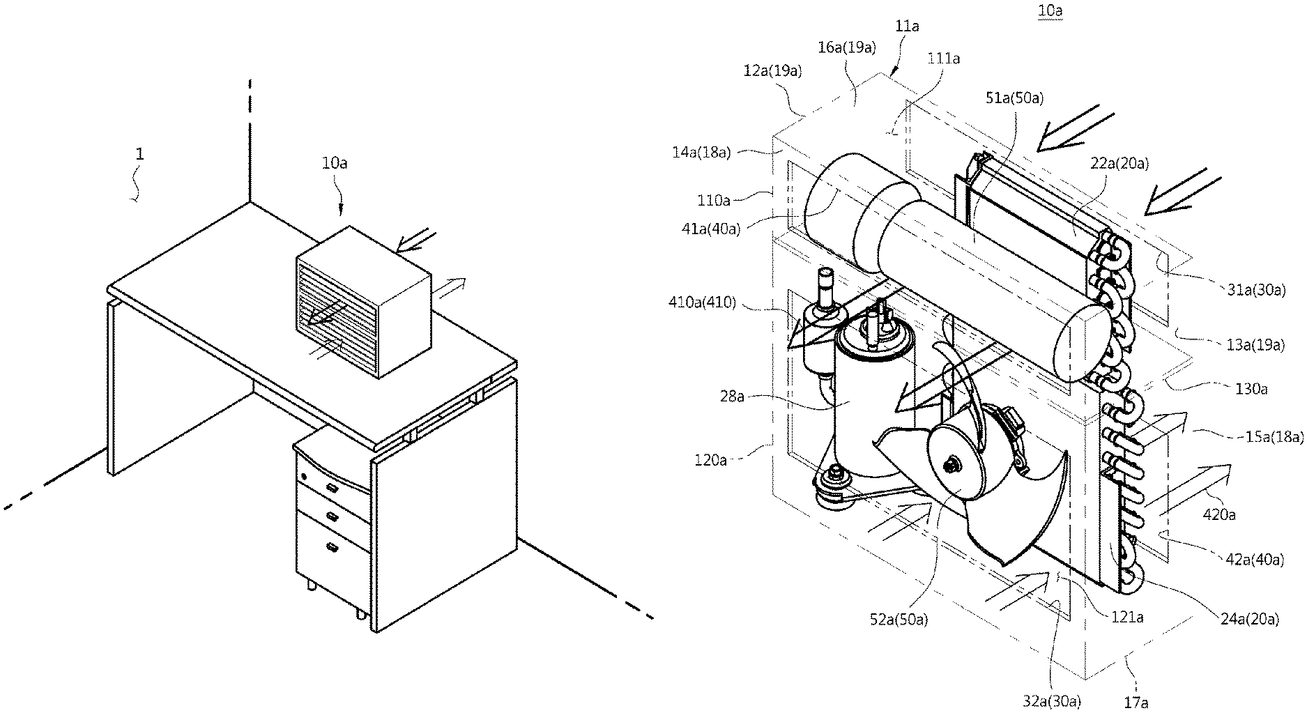
FIG. 1 is a view showing an air conditioner 10a according to a first embodiment of the present invention.
The air conditioner 10a according to the present invention performs an air conditioning operation with respect to a localized region within an air-conditioned space 1 to be air-conditioned. That is, the air conditioning operation is intensively performed with respect to the localized region rather than the whole of the air-conditioned space 1.
The air conditioner 10a may be provided to be movable. That is, a handle portion (not shown) is movably provided in a main body 11a so that the air conditioner 10a may be movable to a required position within the air-conditioned space 1. According to an embodiment of the present invention, the air conditioner 10a may discharge air-conditioned discharge air only to a predetermined space, and thereby may be provided to be miniaturized.
FIG. 1b is a perspective view showing an air conditioner 10a according to a first embodiment of the present invention.
The air conditioner 10a includes the main body 11a, a heat exchanger 20a, and an expansion device 26a. The heat exchanger 20a may include a condenser 24a and an evaporator 22a.
The main body 11a is provided to form an appearance thereof. The main body 11a may be formed by a plurality of appearance panels forming an appearance thereof. The main body 11a may have a substantially hexahedral shape, and provided to partition an inner structure and the outside.
The appearance panel includes left and right panels 12a and 13a forming left and right surfaces thereof, a front panel 14a forming a front surface thereof, a rear panel 15a forming a rear surface thereof, and upper and lower panels 16a and 17a formed on upper and lower portions thereof.
The main body 11a may include a suction port 30a for introducing air from the outside and a discharge port 40a for discharging air inside the main body 11a to the outside.
The main body 11a may include a first main body 110a and a second main body 120a. The first main body 110a and the second main body 120a may be partitioned. Specifically, the first main body 110a and the second main body 120a may be partitioned so as to prevent air from flowing between the first main body 110a and the second main body 120a. In the main body 11a, a partition wall 130a for separating the first main body 110a and the second main body 120a may be provided.
The first main body 110a may function as an indoor unit of a split type air conditioner, and include the evaporator 22a and a first blowing fan 51a which will be described later. The main body 120a may function as an outdoor unit of the split type air conditioner, and include the condenser 24a and a second blowing fan 52a which will be described later. However, the present invention is not limited thereto, and thus the first main body 110a may function as the outdoor unit and the second main body 120a may function as the indoor unit. The evaporator 22a is arranged inside the first main body 110a, and thereby the inside of the first main body 110a may be referred to as an evaporation space 111a, and the condenser 24a is arranged inside the second main body 120a and thereby the inside of the second main body 120a may be referred to as a condensation space 121a.
A compressor 28a compresses a refrigerant into a high temperature and high pressure state to discharge the compressed refrigerant, and the compressed refrigerant flows into the condenser 24a. The condenser 24a condenses the refrigerant compressed by the compressor 28a into a liquid phase. Heat is emitted to the surroundings through a condensation process.
The expansion device 26a may expand a liquid refrigerant in the high temperature and high pressure state condensed by the condenser 24a into a liquid refrigerant in a low pressure state, and the evaporator 22a may evaporate the refrigerant expanded by the expansion device 26a while attaining refrigeration effects by heat exchange with an object to be cooled using evaporation latent heat of the refrigerant and allow the refrigerant in a low temperature and low pressure state to return to the compressor 28a.
The compressor 28a may be provided to be heavy, and thereby arranged in a lower portion inside the main body 11a. Thus, the overall center of gravity of the air conditioner 10a is positioned downward, so that the air conditioner 10a may be stably supported.
The air conditioner 10a according to the present invention is to perform air conditioning with respect to a predetermined region rather than the whole of the air-conditioned space 1, and therefore a compression date of the refrigerant may be provided to be smaller compared to the air conditioner 10a to perform air conditioning with respect to the whole of the air-conditioned space 1. That is, power consumption of the compressor 28a applied to the air conditioner 10a according to the present invention may be smaller than that of the compressor 28a of the air conditioner 10a to perform air conditioning with respect to the whole of the air-conditioned space 1. According to the present embodiment, the power consumption of the compressor 28a is provided to be smaller than 300 W. Thus, the air conditioner 10a may perform air conditioning with respect to the predetermined region of the air-conditioned space 1.
In the first main body 110a, a first suction port 31a through which external air is introduced and a first discharge port 41a through which the air introduced through the first suction port 31a is discharged may be provided. In the second main body 120, a second suction port 32a through which external air is introduced and a second discharge port 42a through which the air introduced through the second suction port 32a is discharged may be provided.
The air conditioner 10a according to the present invention performs air conditioning with respect to the predetermined region of the air-conditioned space 1, and therefore the first discharge port 41a and the second discharge port 42a are arranged within the same air-conditioned space 1. That is, air cooled through the evaporator 22a is discharged through the first discharge port 41a, air heated through the condenser 24a is discharged through the second discharge port 42a, and the first discharge port 41a and the second discharge port 42a are arranged within the same air-conditioned space 1. In an operation process of the air conditioner 10a, the first discharge port 41a is allowed to face a predetermined region in the air-conditioned space 1, and therefore air conditioning may be performed with respect to the corresponding region.
The first discharge port 41a and the second discharge port 42a may be arranged so as to be spaced apart from each other. That is, the air discharged from the first discharge port 41a and the air discharged from the second discharge port 42a may be prevented from being mixed together. In addition, the first discharge port 41a and the second discharge port 42a are spaced apart from each other, so that the air discharged from the second discharge port 42a may be arranged so as not to affect the predetermined region on which air conditioning is to be performed.
Specifically, the first discharge port 41a may be provided in any one of the plurality of appearance panels, and the second discharge port 42a may be provided in another one of the plurality of appearance panels. In the present embodiment, the first discharge port 41a may be arranged in the front panel 14a and the second discharge port 42a may be arranged in the rear panel 15a so that the air discharged from the first discharge port 41a and the air discharged from the second discharge port 42a are provided so as not to affect each other. That is, when it is assumed that an air flow of the air discharged from the first discharge port 41a is first discharge air 410a and an air flow of the air discharged from the second discharge port 42a is second discharge air 420a, the first discharge port 41a and the second discharge port 42a may be provided in such a manner that the first discharge air 410a and the second discharge air 420a are discharged so as not to interfere with each other.
The air conditioner 10a may include a blowing fan 50a.
The blowing fan 50a is arranged adjacent to the heat exchanger 20a so that air heat-exchanged with the heat exchanger 20a is allowed to flow in and out. Specifically, the blowing fan 50a includes the first blowing fan 51a arranged adjacent to the evaporator 22a and the second blowing fan 52a arranged adjacent to the condenser 24a.
The first blowing fan 51a discharges air that is introduced into the air-conditioned space 1 to be heat-exchanged with the evaporator 22a to a predetermined region of the air-conditioned space 1 through the first discharge port 41a, and the second blowing fan 52a discharges air that is introduced into the air-conditioned space 1 to be heat-exchanged with the condenser 24a to the air-conditioned space 1 through the second discharge port 42a.
The type of the blowing fan 50a is not limited, and may include at least one of a cross-flow fan, a sirocco fan, and a propeller fan. In the present embodiment, the cross-flow fan may be applicable as the first blowing fan 51a and the propeller fan may be applicable as the second blowing fan 52a, but the present invention is not limited thereto. Thus, other types of fans may be applicable.
In the present embodiment, the main body 11a is provided to have a slim shape in a front and back direction. That is, when it is assumed that the front panel 14a and the rear panel 15a are first surfaces 18a, and the left panel 12a, the right panel 13a, the upper panel, and the lower panel are second surfaces 19a, the main body 11a includes a pair of first surfaces 18a facing each other and the second surfaces 19a each having a smaller area than that of the first surface 18a between the pair of first surfaces 18a. The condenser 24a and the evaporator 22a may be arranged side by side with the first surface 18a. The main body 11a may have a slim shape in the front and back direction, and therefore the condenser 24a and the evaporator 22a may be arranged substantially side by side with each other.
In the present embodiment, the evaporator 22a and the condenser 24a may be vertically arranged. Thus, the first main body 110a and the second main body 120a may be vertically arranged. The evaporator 22a and the condenser 24a are vertically arranged side by side and condensed water generated from the evaporator 22a falls down to the condenser 24a, so that heat exchange efficiency in the condenser 24a may be improved.
The first blowing fan 51a may be provided inside the first main body 110a, and discharge the air heat-exchanged with the evaporator 22a through the first discharge port 41a to the predetermined region of the air-conditioned space 1.
The second blowing fan 52a may be provided inside the second main body 120a and discharge the air heat-exchanged with the condenser 24a through the second discharge port 42a to the air-conditioned space 1. The first blowing fan 51a and the second blowing fan 52a allow the air discharged from the inside of the main body 11a to blow in mutually different directions, and therefore the air discharged by the first blowing fan 51a and the second blowing fan 52a may be prevented from being mixed together.
Hereinafter, an air conditioner 10b according to a second embodiment of the present invention will be described.
Prior to description, reference numerals are given as numerals according to configuration and alphabets according to embodiments in order to distinguish a plurality of embodiments. Thus, even when the alphabets are different, reference numerals having the same numerals may have the same configuration. Descriptions of reference numerals in embodiments which will be described below are the same as those of the reference numerals of the above-described embodiment. Thus, repeated description with respect to the above-described embodiment will be omitted. In the second embodiment unlike the first embodiment, the end of each reference numeral is given as "b".
FIG. 2 is a perspective view showing an air conditioner according to a second embodiment of the present invention.
In the present embodiment, the type of a blowing fan 50b and a blowing direction are different from those in the first embodiment.
In the present embodiment, a main body 11b is provided to have a slim shape in a front and back direction. That is, when it is assumed that a front panel 14b and a rear panel 15b are first surfaces 18b, and a left panel 12b, a right panel 13b, an upper panel, and a lower panel are second surfaces 19b, the main body 11b includes a pair of first surfaces 18b facing each other and second surfaces 19b each having a smaller area than that of the first surface 18b between the pair of first surfaces 18b.
In the present embodiment, both a first blowing fan 51b and a second blowing fan 52b may be formed as a sirocco fan.
Both a first suction port 31b and a second suction port 32b may be provided in the rear panel 15b. A first discharge port 41b and a second discharge port 42b may be respectively provided in the left panel 12b and the right panel 13b. Through this structure, first discharge air 410b and second discharge air 420b are prevented from interfering with each other. However, positions of a suction port 30b and a discharge port 40b are not limited thereto.
Hereinafter, an air conditioner 10c according to a third embodiment of the present invention will be described.
Repeated description with respect to the above-described embodiments will be omitted. In the third embodiment unlike the first embodiment, the end of each reference numeral is given as "c".
FIG. 3 is a perspective view showing an air conditioner according to a third embodiment of the present invention.
In the present embodiment, arrangement of components is different from that in the first embodiment.
In the present embodiment, a main body 11c may be provided to have a slim shape in a front and back direction. That is, when it is assumed that a front panel 14c and a rear panel 15c are first surfaces 18c and a left panel 12c, a right panel 13c, an upper panel, and a lower panel are second surfaces 19c, the main body 11c includes a pair of first surfaces 18c facing each other and second surfaces 19c each having a smaller area than that of the first surface 18c between the pair of first surfaces 18c.
In the present embodiment, an evaporator 22c and a condenser 24c may be arranged on right and left sides. Thus, in the present embodiment, a first main body 110c and a second main body 120c may be arranged on right and left sides. The evaporator 22c and the condenser 24c may be arranged side by side on right and left sides. In the evaporator 22c, condensed water is generated on the surface of the evaporator 22c in a heat exchange process, and the surface of the condenser 24c is wet with the generated condensed water using a drain pump (not shown), thereby improving heat exchange efficiency in the condenser 24c.
Both a first blowing fan 51c and a second blowing fan 52c may be formed as a propeller fan. A first suction port 31c may be provided in the rear panel 15c, a first discharge port 41c may be provided in the front panel 14c, and the first blowing fan 51c may be disposed between the first suction port 31c and the first discharge port 41c. A second suction port 32c may be provided in the front panel 14c, a second discharge port 42c may be provided in the rear panel 15c, and the second blowing fan 52c may be disposed between the second suction port 32c and the second discharge port 42c. Through this structure, first discharge air 410c and second discharge air 420c are prevented from interfering with each other.
Hereinafter, an air conditioner 10d according to a 4th embodiment of the present invention will be described.
Repeated description with respect to the above-described embodiments will be omitted. In the 4th embodiment unlike the first embodiment, the end of each reference numeral is given as "d".
FIG. 4 is a perspective view showing an air conditioner according to a 4th embodiment of the present invention.
In the present embodiment, arrangement of a condenser 24d is different from that in the third embodiment.
In the third embodiment, the evaporator 22c and the condenser 24c are arranged side by side on right and left sides, but in the present embodiment, an evaporator 22d and the condenser 24d are arranged on right and left sides to be spaced apart from each other in a front and back direction.
In the third embodiment, the evaporator 22c is disposed between the first blowing fan 51c and the first suction port 31c, and the condenser 24c is disposed between the second blowing fan 52c and the second discharge port 42c. However, in the 4th embodiment, the evaporator 22d is disposed between a first blowing fan 51d and a first suction port 31d, and the condenser 24d is disposed between a second blowing fan 52d and a second suction port 32d. Through this structure, first discharge air 410d and second discharge air 420d are prevented from interfering with each other.
Hereinafter, an air conditioner 10e according to a 5th embodiment of the present invention will be described.
Repeated description with respect to the above-described embodiments will be omitted. In the 5th embodiment unlike the first embodiment, the end of each reference numeral is given as "e".
FIG. 5 is a perspective view showing an air conditioner according to a 5th embodiment of the present invention.
In the present embodiment, a main body 11e may be provided to have a slim shape in a front and back direction. That is, when it is assumed that a front panel 14e and a rear panel 15e are first surfaces 18e, and a left panel 12e, a right panel 13e, an upper panel, and a lower panel are second surfaces 19e, the main body 11e includes a pair of first surfaces 18e facing each other, and second surfaces 19e each having a smaller area than that of the first surface 18e between the pair of first surfaces 18e.
In the present embodiment, both a first blowing fan 51e and a second blowing fan 52e may be formed as a cross-flow fan. The first blowing fan 51e and the second blowing fan 52e may be vertically disposed.
An evaporator 22e is provided adjacent to the first blowing fan 51e, and a condenser 24e is disposed adjacent to the second blowing fan 52e. A first suction port 31e may be provided in the rear panel 15e, a first discharge port 41e may be disposed in the front panel 14e, a second suction port 32e may be provided in the front panel 14e, and a second discharge port 42e may be disposed in the rear panel 15e. Through this, first discharge air 410e and second discharge air 420e are prevented from interfering with each other.
Hereinafter, an air conditioner 10f according to a 6th embodiment of the present invention will be described.
Repeated description with respect to the above-described embodiments will be omitted. In the 6th embodiment unlike the first embodiment, the end of each reference numeral is given as "f".
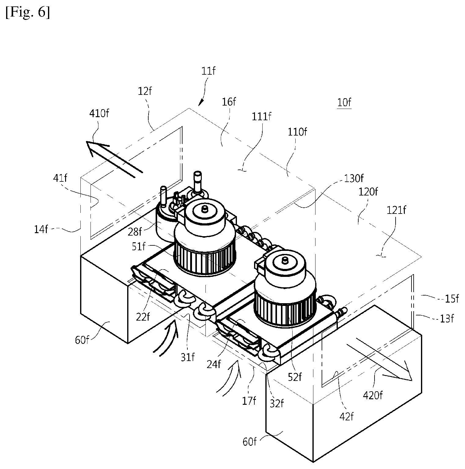
FIG. 6 is a perspective view showing an air conditioner according to a 6th embodiment of the present invention.
In the present embodiment, the air conditioner 10f includes a mounting portion 60f.
The mounting portion 60f is provided below a main body 11f, and provided so as to stably support the main body 11f on the floor. In addition, the mounting portion 60f is provided to separate a support surface on which the air conditioner is supported and the main body 11f.
A first suction port 31f and a second suction port 32f may be provided on a lower portion of the main body 11f. That is, the suction ports 31f and 32f are provided to correspond to the support surface so as not to be easily exposed from the outside.
An evaporator 22f and a condenser 24f may be respectively arranged on inner sides of the first suction port 31f and the second suction port 32f. In addition, the evaporator 22f and the condenser 24f may be arranged on the same plane parallel to the suction ports 31f and 32f.
The first suction port 31f and the second suction port 32f are provided on a lower panel 17f of the main body 11f. The main body 11f is provided to be spaced apart from the bottom surface by the mounting portion 60f, and therefore external air may be introduced into the main body 11f through the first suction port 31f and the second suction port 32f of the lower panel 17f.
Both a first blowing fan 51f and a second blowing fan 52f may be formed as a sirocco fan. In addition, a first discharge port 41f and a second discharge port 42f may be respectively provided in a left panel 12f and a right panel 13f. The evaporator 22f and the condenser 24f may be arranged to correspond to the first suction port 31f and the second suction port 32f.
Through this, air introduced through the first suction port 31f is discharged to the first discharge port 41f via the evaporator 22f and the first blowing fan 51f, and air introduced through the second suction port 32f is discharged to the second discharge port 42f via the condenser 24f and the second blowing fan 52f. Through this structure, first discharge air 410f and second discharge air 420f may be prevented from interfering with each other.
Hereinafter, an air conditioner 10g according to a 7th embodiment of the present invention will be described.
Repeated description with respect to the above-described embodiments will be omitted. In the 7th embodiment unlike the first embodiment, the end of each reference numeral is given as "g".
FIG. 7 is a perspective view showing an air conditioner according to a 7th embodiment of the present invention.
In the present embodiment, arrangement of an evaporator 22g and a condenser 24g is different from that in the 6th embodiment.
The evaporator 22g and the condenser 24g may be provided so as to be spaced apart from each other at a predetermined angle with respect to a lower panel 17g. That is, the evaporator 22g and the condenser 24g may be arranged so as to be inclined at a predetermined angle from suction ports 31g and 32g. In addition, the evaporator 22g and the condenser 24g may be arranged on the same plane parallel to the suction ports 31g and 32g.
A first discharge port 41g may be provided in a right panel 13g, and a second discharge port 42g may be provided in a left panel 12g. Both a first blowing fan 51g and a second blowing fan 52g may be formed as a sirocco fan.
The first suction port 31g may be provided in an upper panel 16g, and air passing through the evaporator 22g may be discharged to the first discharge port 41g of the right panel 13g by the first blowing fan 51g. The second suction port 32g may be provided in the lower panel 17g, and air passing through the condenser 24g may be discharged to the second discharge port 42g of the left panel 12g by the second blowing fan 52g.
A louver portion 62g may be provided in the evaporator 22g and the condenser 24g. The louver portion 62g may be provided to guide air passing through the inside of a first main body 110g to the evaporator 22g and the first blowing fan 51g. In addition, the louver portion 62g may be provided to guide air passing through the inside of a second main body 120g to the condenser 24g and the second blowing fan 52g.
Hereinafter, an air conditioner 10h according to an 8th embodiment of the present invention will be described.
Repeated description with respect to the above-described embodiments will be omitted. In the 8th embodiment unlike the first embodiment, the end of each reference numeral is given as "h".
FIG. 8 is a perspective view showing an air conditioner according to an 8th embodiment of the present invention.
In the present embodiment, a main body 11h is provided to have a height larger than a width of a lower surface thereof. That is, the main body 11h may be provided to have a tower shape. The shape of the main body 11h is not limited, and the main body 11h may be provided to have a cylindrical shape with circular upper and lower surfaces thereof.
In the present embodiment, a first blowing fan 51h and a second blowing fan 52h may be vertically arranged side by side. In addition, the first blowing fan 51h and the second blowing fan 52h may be applicable as a cross-flow fan, and arranged long in a vertical direction.
In addition, the first blowing fan 51h and the second blowing fan 52h may be divided into a first region and a second region by the cross-flow fan. Each of the blowing fans 51h and 52h may include the first region and the second region adjacent to the first region in a longitudinal direction of the cross-flow fan. In the first region, an evaporator 22h may be disposed, and in the second region, a condenser 24h may be disposed. The first region and the second region may be provided to be connected to each other, or arranged to be spaced apart from each other while having a predetermined space therebetween.
The first blowing fan 51h and the second blowing fan 52h may be provided to be respectively divided into the first region and the second region so as to correspond to a size of each of the evaporator 22h and the condenser 24h.
The first blowing fan 51h and the second blowing fan 52h may be provided to be rotated together using a single motor. The first blowing fan 51h and the second blowing fan 52h are rotated together in the same rotational direction using the single motor, and therefore blades of the first blowing fan 51h and the second blowing fan 52h may be arranged in the opposite direction to each other.
Through this structure, the first blowing fan 51h and the second blowing fan 52h may be rotated in the same direction, but first discharge air 410h and second discharge air 420h may have different directions from each other.
The evaporator 22h and the condenser 24h may be provided adjacent to the first blowing fan 51h and the second blowing fan 52h. In addition, the evaporator 22h and the condenser 24h may be formed into an arc shape having a predetermined curvature, and thereby surrounded by a predetermined section of the first blowing fan 51h and the second blowing fan 52h, respectively.
The evaporator 22h and the condenser 24h may be arranged opposite to each other with respect to a rotational center of each of the first blowing fan 51h and the second blowing fan 52h, and arranged to be vertically spaced apart from each other.
A first suction port 31h, a second suction port 32h, a first discharge port 41h, and a second discharge port 42h may be provided so as to correspond to this, and each of suction ports 30h and each of discharge ports 40h may be arranged to cross each other, so that the first discharge air 410h and the second discharge air 420h may be prevented from interfering with each other.
Hereinafter, an air conditioner 10i according to a 9th embodiment of the present invention will be described.
Repeated description with respect to the above-described embodiments will be omitted. In the 9th embodiment unlike the first embodiment, the end of each reference numeral is given as "i".
FIG. 9 is a perspective view showing an air conditioner according to a 9th embodiment of the present invention.
In the present embodiment, structures of an evaporator 22i and a condenser 24i are different from those in the 8th embodiment.
The evaporator 22i and the condenser 24i may be arranged to have a plane shape, arranged opposite to each other with respect to a rotational center of each of a first blowing fan 51i and a second blowing fan 52i, and vertically arranged to be spaced apart from each other.
Hereinafter, an air conditioner 10j according to a 10th embodiment of the present invention will be described.
Repeated description with respect to the above-described embodiments will be omitted. In the 10th embodiment unlike the first embodiment, the end of each reference numeral is given as "j".
FIG. 10 is a perspective view showing an air conditioner according to a 10th embodiment of the present invention.
In the present embodiment, a structure of a blowing fan 50j is different from that in the 8th embodiment.
In the 8th embodiment, the first blowing fan 51h and the second blowing fan 52h are provided to be rotated together using a single motor, but in the present embodiment, each of a first blowing fan 51j and a second blowing fan 52j may be operated using its own motor.
A first suction port 31j may be provided in a left panel 12j, and a first discharge port 41j may be provided in a right panel 13j. In contrast, a second suction port 32j may be provided in the right panel 13j, and a second discharge port 42j may be provided in the left panel 12j.
Hereinafter, an air conditioner 10k according to an 11th embodiment of the present invention will be described.
Repeated description with respect to the above-described embodiments will be omitted. In the 11th embodiment unlike the first embodiment, the end of each reference numeral is given as "k".
FIG. 11 is a perspective view showing an air conditioner according to an 11th embodiment of the present invention.
A main body 11k includes a left panel 12k, a right panel 13k, a rear panel 15k, and a front panel 14k. In addition, the main body 11k includes a discharge main body 63k that is provided in an upper portion of the main body 11k and formed into a disc shape so as to encircle a blowing fan 50k. The discharge main body 63k may be included in a first main body 110k.
A first suction port 31k and a second suction port 32k may be provided on the left panel 12k. In the present embodiment, the first main body 110k may be provided in an upper portion of the main body 11k and a second main body 120k is provided in a lower portion thereof, and therefore the first suction port 31k may be provided in an upper portion of the left panel 12k and the second suction port 32k may be provided in a lower portion thereof.
The first main body 110k may include the discharge main body 63k.
A first blowing fan 51k may be disposed inside the discharge main body 63k. The first blowing fan 51k may be disposed side by side with a support surface on which the main body 11k is supported, and discharge air heat-exchanged with an evaporator 22k in a direction parallel to the support surface. The discharge main body 63k may be formed into a substantially disc shape.
A first discharge port 41k may be provided in the discharge main body 63k, and a second discharge port 42k may be provided in the rear panel 15k. The first discharge port 41k may be provided to have an arc shape along a circumference of the discharge main body 63k. Through this shape, air discharged from the first discharge port 41k may be discharged in a planar direction parallel to the support surface.
The evaporator 22k may be provided inside the first main body 110k, and air passing through the evaporator 22k flows upward and is discharged to a front side of the main body 11k by the first discharge port 41k provided on a front side of the discharge main body 63k by a sirocco fan that is the first blowing fan 51k.
A condenser 24k may be provided inside the second main body 120k, and air passing through the condenser 24k flows rearward and is discharged to a rear side of the main body 11k by the second discharge port 42k provided in the rear panel 15k by the sirocco fan that is a second blowing fan 52k. That is, the second blowing fan 52k may discharge air heat-exchanged with the condenser in a direction different from an air discharge direction by the first blowing fan 51k.
Hereinafter, an air conditioner 10l according to a 12th embodiment of the present invention will be described.
Repeated description with respect to the above-described embodiments will be omitted. In the 12th embodiment unlike the first embodiment, the end of each reference numeral is given as "l".
FIG. 12 is a perspective view showing an air conditioner according to a 12th embodiment of the present invention.
A main body 11l may be provided to have a hemispherical shape. Specifically, the main body 11l may include a circular flat panel 70l provided to be flat and a curved panel 71l formed into a hemispherical curved surface.
The main body 11l may include a first main body 110l and a second main body 120l.
The first main body 110l and the second main body 120l may be arranged to form a half of the hemispherical shape from the hemispherical main body 11l.
In the present embodiment, a first suction port 31l, a second suction port 32l, a first discharge port 41l, and a second discharge port 42l may be provided on the curved panel 71l.
An evaporator 22l and a condenser 24l may be arranged on an inner surface of the curved panel 71l, and arranged opposite to each other. The first suction port 31l and the second suction port 32l may be provided on the curved panel 71l to correspond to the evaporator 22l and the condenser 24l, and arranged opposite to each other. However, the present invention is not limited thereto, and the first suction port 31l and the second suction port 32l may be arranged any one of the curved panel 71l and the flat panel 70l.
The first discharge port 41l and the second discharge port 42l may be arranged opposite to each other between the first suction port 31l and the second suction port 32l. In other words, the first discharge port 41l and the second discharge port 42l may be arranged opposite to each other with respect to a center of the curved panel 71l.
A first blowing fan 51l and a second blowing fan 52l may be arranged inside the evaporator 22l and the condenser 24l, and respectively discharge air introduced from the first suction port 31l and the second suction port 32l to the first discharge port 41l and the second discharge port 42l arranged between the first suction port 31l and the second suction port 32l by converting a flow path of the air introduced from the first suction port 31l and the second suction port 32l. Both the first blowing fan 51l and the second blowing fan 52l may be applicable as a sirocco fan.
Hereinafter, an air conditioner 10m according to a 13th embodiment of the present invention will be described.
Repeated description with respect to the above-described embodiments will be omitted. In the 13th embodiment unlike the first embodiment, the end of each reference numeral is given as "m".
FIG. 13 is a perspective view showing an air conditioner according to a 13th embodiment of the present invention.
In the present embodiment, arrangement of the air conditioner 10m, an evaporator 22m, a condenser 24m, a blowing fan 50m, a suction port 30m, and a discharge port 40m is different from that in the 12th embodiment.
A flat panel 70m is disposed to be inclined at a predetermined angle with respect to a bottom surface on which a main body 11m is supported, and a curved panel 71m may be provided to be supported by the bottom surface.
The condenser 24m is disposed to be perpendicular to the bottom surface. The evaporator 22m may be disposed on an inner surface of the flat panel 70m so as to be side by side with the flat panel 70m. A first suction port 31m may be provided on the flat panel 70m, so that air may be introduced into the evaporator 22m through the first suction port 31m. A second suction port 32m may be provided on the curved panel 71m, so that air may be introduced into the condenser 24m.
A first discharge port 41m may be provided on the curved panel 71m, and provided in an upper portion of the main body 11m. Through this, air introduced into the flat panel 70m may be discharged to the upper portion of the main body 11m via the evaporator 22m. A second discharge port 42m may be provided on the curved panel 71m, and provided on a side portion of the main body 11m. Both a first blowing fan 51m and a second blowing fan 52m may be applicable as a sirocco fan.
Hereinafter, an air conditioner 10n according to a 14th embodiment of the present invention will be described.
Repeated description with respect to the above-described embodiments will be omitted. In the 14th embodiment unlike the first embodiment, the end of each reference numeral is given as "n".
FIG. 14 is a perspective view showing an air conditioner according to a 14th embodiment of the present invention.
A main body 11n may be provided to have a triangular prism shape while having a substantially triangular cross-section.
The main body 11n may include an upper panel 16n, a lower panel 17n, and a plurality of side panels 12n.
The main body 11n may be provided to have a triangular prism shape, and therefore the number of the side panels is three. In the present embodiment, the main body 11n is formed into a triangular prism shape with a triangular cross-section, but is not limited thereto, and the main body 11n may be formed into a polyprism shape with a polygonal cross-section.
An evaporator 22n and a condenser 24n may be vertically arranged on any one of the plurality of side panels 12n. That is, the evaporator 22n may be disposed in an upper portion of the side panel and the condenser 24n may be disposed in a lower portion thereof. To correspond to the evaporator 22n and the condenser 24n, a first suction port 31n and a second suction port 32n may be vertically arranged on the side panel 12n.
A first discharge port 41n and a second discharge port 42n may be arranged on the remaining plurality of side panels 12n excluding the side panel on which the evaporator 22n and the condenser 24n are arranged among the plurality of side panels 12n. In the present embodiment, the first suction port 31n and the second suction port 32n are arranged on one of three side panels 12n, the first discharge port 41n is disposed on another one thereof, and the second discharge port 42n is disposed on still another one thereof.
Both a first blowing fan 51n and a second blowing fan (not shown) may be used as a cross-flow fan, and the first blowing fan 51n and the second blowing fan may be vertically arranged side by side to change a flow path direction of air introduced from the first suction port 31n and the second suction port 32n.
Hereinafter, an air conditioner 10o according to a 15th embodiment of the present invention will be described.
Repeated description with respect to the above-described embodiments will be omitted. In the 15th embodiment unlike the first embodiment, the end of each reference numeral is given as "o".
FIG. 15 is a perspective view showing an air conditioner according to a 15th embodiment of the present invention.
In the present embodiment, arrangement of internal components of an air conditioner and a main body is different from that in the 14th embodiment.
A main body 11o includes a first main body 110o provided in an upper portion thereof and a second main body 120o provided in a lower portion thereof.
A first discharge port 41o and a second suction port 32o may be arranged in any one of a plurality of side panels 12o, and a second discharge port 42o and a first suction port 31o may be arranged in another one thereof.
Both a first blowing fan 51o and a second blowing fan 52o may be used as a sirocco fan and vertically arranged side by side, so that a flow path direction of air introduced from the first suction port 31o and the second suction port 32o may be changed.
Hereinafter, an air conditioner 10p according to a 16th embodiment of the present invention will be described.
Repeated description with respect to the above-described embodiments will be omitted. In the 16th embodiment unlike the first embodiment, the end of each reference numeral is given as "p".
FIG. 16 is a perspective view showing an air conditioner according to a 16th embodiment of the present invention.
A main body 11p may be provided to have a cylinder shape. The main body 11p includes an upper panel 16p, a lower panel 17p, and a side panel 12p that connects the upper panel 16p and the lower panel 17p.
Inside the main body 11p, an evaporator 22p and a condenser 24p may be arranged to face each other. That is, the evaporator 22p and the condenser 24p may be arranged on an inner side of the side panel, and arranged opposite to each other. A first suction port 31p and a second suction port 32p may be arranged on the side panel so as to correspond to the evaporator 22p and the condenser 24p.
A first blowing fan 51p and a second blowing fan 52p may arranged between the evaporator 22p and the condenser 24p, and a sirocco fan may be applicable in order to change a flow path. A first discharge port 41p and a second discharge port 42p may be provided on the side panel so that air introduced through the first suction port 31p and the second suction port 32p may be discharged in a direction perpendicular to a center of the main body 11p. That is, the air is sucked in a right and left direction of the main body 11p and discharged in a front and back direction.
The first blowing fan 51p and the second blowing fan 52p may be provided to be rotated using a single motor.
Hereinafter, an air conditioner 10q according to a 17th embodiment of the present invention will be described.
Repeated description with respect to the above-described embodiments will be omitted. In the 17th embodiment unlike the first embodiment, the end of each reference numeral is given as "q".
FIG. 17 is a perspective view showing an air conditioner according to a 17th embodiment of the present invention.
A main body 11q includes a first main body 110q in which an evaporator 22q is disposed and a second main body 120q in which a condenser 24q is disposed.
The first main body 110q and the second main body 120q may be provided so as to be spaced apart from each other, and connected to each other through a pipe. Movement of a refrigerant between the first main body 110q and the second main body 120q may be carried out through a pipe 75q.
In the first main body 110q, the evaporator 22q and a first blowing fan 51q may be arranged, and in the second main body 120q, the condenser 24q and a second blowing fan 52q may be arranged.
Through this structure, cooling may be performed through the first main body 110q, and heating may be performed through the second main body 120q.
Hereinafter, an air conditioner 10r according to an 18th embodiment of the present invention will be described.
Repeated description with respect to the above-described embodiments will be omitted. In the 18th embodiment unlike the first embodiment, the end of each reference numeral is given as "r".
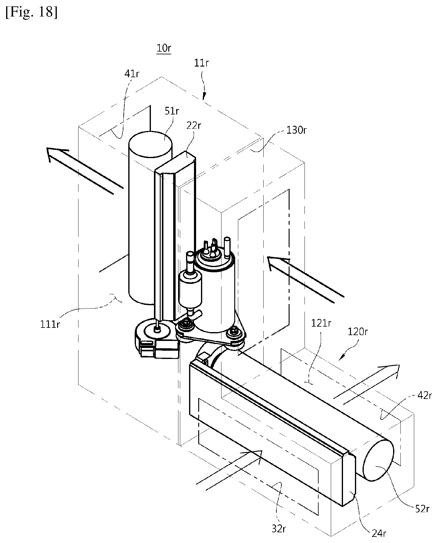
FIG. 18 is a perspective view showing an air conditioner according to an 18th embodiment of the present invention.
A main body 11r includes a first main body 110r in which an evaporator 22r is disposed and a second main body 120r in which a condenser 24r is disposed. The first main body 110r and the second main body 120r may be provided to have different shapes from each other, and provided adjacent to each other.
In the first main body 110r, the evaporator 22r and a first blowing fan 51r may be arranged, and in the second main body 120r, the condenser 24r and a second blowing fan 52r may be disposed.
Through this structure, cooling may be performed through the first main body 110r and heating may be performed through the second main body 120r.
While the invention has been shown and described with reference to certain exemplary embodiments thereof, it will be understood by those skilled in the art that various changes in form and details may be made therein without departing from the spirit and scope of the invention as defined by the appended claims.
* * * * *
D00000
D00001
D00002
D00003
D00004
D00005
D00006
D00007
D00008
D00009
D00010
D00011
D00012

D00013

D00014

D00015

D00016

D00017
XML
uspto.report is an independent third-party trademark research tool that is not affiliated, endorsed, or sponsored by the United States Patent and Trademark Office (USPTO) or any other governmental organization. The information provided by uspto.report is based on publicly available data at the time of writing and is intended for informational purposes only.
While we strive to provide accurate and up-to-date information, we do not guarantee the accuracy, completeness, reliability, or suitability of the information displayed on this site. The use of this site is at your own risk. Any reliance you place on such information is therefore strictly at your own risk.
All official trademark data, including owner information, should be verified by visiting the official USPTO website at www.uspto.gov. This site is not intended to replace professional legal advice and should not be used as a substitute for consulting with a legal professional who is knowledgeable about trademark law.