Method for creating airfoil leading and trailing edges
Rizzo, Jr.
U.S. patent number 10,675,697 [Application Number 15/022,571] was granted by the patent office on 2020-06-09 for method for creating airfoil leading and trailing edges. This patent grant is currently assigned to Raytheon Technologies Corporation. The grantee listed for this patent is United Technologies Corporation. Invention is credited to John P. Rizzo, Jr..


| United States Patent | 10,675,697 |
| Rizzo, Jr. | June 9, 2020 |
Method for creating airfoil leading and trailing edges
Abstract
A method of forming a component using electro-chemical machining includes the steps of providing a shield in a current distribution path between a workpiece and an electrode, with the shield concentrating current distribution upon an end of the workpiece.
| Inventors: | Rizzo, Jr.; John P. (Vernon, CT) | ||||||||||
|---|---|---|---|---|---|---|---|---|---|---|---|
| Applicant: |
|
||||||||||
| Assignee: | Raytheon Technologies
Corporation (Farmington, CT) |
||||||||||
| Family ID: | 52993353 | ||||||||||
| Appl. No.: | 15/022,571 | ||||||||||
| Filed: | September 24, 2014 | ||||||||||
| PCT Filed: | September 24, 2014 | ||||||||||
| PCT No.: | PCT/US2014/057174 | ||||||||||
| 371(c)(1),(2),(4) Date: | March 17, 2016 | ||||||||||
| PCT Pub. No.: | WO2015/060975 | ||||||||||
| PCT Pub. Date: | April 30, 2015 |
Prior Publication Data
| Document Identifier | Publication Date | |
|---|---|---|
| US 20160221096 A1 | Aug 4, 2016 | |
Related U.S. Patent Documents
| Application Number | Filing Date | Patent Number | Issue Date | ||
|---|---|---|---|---|---|
| 61895035 | Oct 24, 2013 | ||||
| Current U.S. Class: | 1/1 |
| Current CPC Class: | C25D 7/00 (20130101); B23H 3/04 (20130101); B23H 9/10 (20130101); B23H 7/38 (20130101) |
| Current International Class: | C25D 7/00 (20060101); B23H 7/38 (20060101); B23H 3/04 (20060101); B23H 9/10 (20060101) |
References Cited [Referenced By]
U.S. Patent Documents
| 3514390 | May 1970 | Stark et al. |
| 5256262 | October 1993 | Blomsterberg |
| 5985127 | November 1999 | Greenslade |
| 9682437 | June 2017 | Platz et al. |
| 2010/0051475 | March 2010 | Eto, II et al. |
| 2011/0262771 | October 2011 | Trimmer et al. |
| 2011/0290663 | December 2011 | Luo et al. |
| 69601849 | Sep 1999 | DE | |||
| 02243800 | Sep 1990 | JP | |||
Other References
|
International Preliminary Report on Patentability for International Application No. PCT/US2014/057174 dated May 6, 2016. cited by applicant . International Search Report from corresponding PCT/US14/57174. cited by applicant . Supplementary European Search Report for European Application No. 14856563.3 dated Jul. 10, 2017. cited by applicant. |
Primary Examiner: Wittenberg; Stefanie S
Attorney, Agent or Firm: Carlson, Gaskey & Olds, P.C.
Parent Case Text
CROSS-REFERENCE TO RELATED APPLICATION
This application claims priority to U.S. Provisional Application No. 61/895,035, filed Oct. 24, 2013.
Claims
The invention claimed is:
1. A method of forming a component using electro-chemical machining comprising the steps of: providing a shield in a current distribution path between a workpiece and an electrode, with said shield concentrating current distribution upon at least one end of the workpiece; wherein said shield includes two parallel shields that are spaced on sides of said workpiece; wherein ends of said parallel shields deflect current at said at least one end of said workpiece; and providing a current passing between said electrode and said workpiece, with said current being deflected around ends of each of said shields, and concentrated upon said at least one end of said workpiece, with said at least one end of said workpiece being one of a leading and trailing edge of an airfoil.
2. The method as set forth in claim 1, wherein said shield is formed of non-conductive material.
3. The method as set forth in claim 2, wherein said shield is formed of a plastic.
4. The method as set forth in claim 1, wherein electro-chemical machining is also utilized to form the workpiece to an intermediate shape prior to the use of the shield to form said one of said leading and trailing edges.
Description
BACKGROUND OF THE INVENTION
This application relates to a method of using a non-contact machining method, such as electro-chemical machining (ECM) or electrolytic machining to form airfoil leading and trailing edges.
Airfoils are utilized in any number of applications. As an example, a gas turbine engine commonly has airfoils associated with a number of rotating blades and a number of static vanes. A number of methods of manufacture are utilized to form the airfoils.
Typically, an airfoil could be said to have a pressure side, a suction side, a leading edge and a trailing edge. Optimal edge shapes often include complex curves, such as spline, parabolas or ellipses.
One popular method of manufacturing airfoils is electro-chemical machining (ECM).
In a common ECM system, a conductive workpiece is machined to form the airfoil. A voltage is connected to the workpiece and to an electrode (cathode). The workpiece is in a chamber with an electrolytic fluid. Precision ECM systems use complex cathode shapes that are place in close proximity to the workpiece to create complex geometry. This technique is expensive and results in long lead time tooling.
Metal is removed from the workpiece and complex shapes may be formed. However, as mentioned above, the leading and trailing edges, and in particular, very small sized edges, challenge traditional precision ECM methods. These methods have not been as effective in forming the desired edges.
SUMMARY OF THE INVENTION
In a featured embodiment, a method of forming a component using electro-chemical machining includes the steps of providing a shield in a current distribution path between a workpiece and an electrode, with the shield concentrating current distribution upon an end of the workpiece.
In another embodiment according to the previous embodiment, the workpiece is to form an airfoil, and the shield concentrating current distribution upon the end of the workpiece is to form at least one of a leading edge and a trailing edge of the airfoil.
In another embodiment according to any of the previous embodiments, the shield is utilized to concentrate the current distribution on both the leading edge and the trailing edge.
In another embodiment according to any of the previous embodiments, the shield includes two parallel shields that are spaced on sides of the workpiece.
In another embodiment according to any of the previous embodiments, ends of the parallel shields deflect current at the one end of the workpiece.
In another embodiment according to any of the previous embodiments, the shield sits between the end of the workpiece and the electrode and includes an aperture for concentrating the current distribution on the one end of the workpiece.
In another embodiment according to any of the previous embodiments, the shield is formed of non-conductive material.
In another embodiment according to any of the previous embodiments, the shield is formed of a plastic.
In another embodiment according to any of the previous embodiments, electro-chemical machining is also utilized to form the workpiece to an intermediate shape prior to using the shield to form the one of the leading and trailing edges.
In another embodiment according to any of the previous embodiments, the shield comprises a pair of parallel spaced shields on sides of the workpiece.
In another embodiment according to any of the previous embodiments, ends of the parallel shields deflect current at the one end of the workpiece.
In another embodiment according to any of the previous embodiments, the shields are formed of non-conductive material.
In another embodiment according to any of the previous embodiments, the shields are formed of a plastic.
In another embodiment according to any of the previous embodiments, the shields are formed of non-conductive material.
In another embodiment according to any of the previous embodiments, the shields are formed of a plastic.
In another embodiment according to any of the previous embodiments, the shield sits between the end of the workpiece. The electrode and the shield include an aperture for concentrating the current distribution on the one end of the workpiece.
In another embodiment according to any of the previous embodiments, the shield is formed of non-conductive material.
In another embodiment according to any of the previous embodiments, the shield is formed of a plastic.
In another embodiment according to any of the previous embodiments, the shield is formed of non-conductive material.
In another embodiment according to any of the previous embodiments, the shield is formed of a plastic.
In another embodiment according to any of the previous embodiments,
These and other features may be best understood from the following drawings and specification.
BRIEF DESCRIPTION OF THE DRAWINGS
FIG. 1 schematically shows an airfoil.
FIG. 2A shows a first method step.
FIG. 2B shows a subsequent method step.
FIG. 3 shows an alternative method.
DETAILED DESCRIPTION
As shown, an airfoil 20, which may be part of a blade, vane or other item within a gas turbine engine, has a curved shape along a central area 22 and extending between a trailing edge 24 and a leading edge 26.
More generally, components may include blades, vanes, tangential outboard injectors, integrally bladed rotors, and impellers. In fact, teachings of this application may even extend to components that do not include an airfoil, but which do require some complex shaping. As can be appreciated from FIG. 1, the trailing edge 24 and the leading edge 26 are curved.
FIG. 2A shows an electro-chemical machining process 126 schematically. As known, an electrolytic fluid 125 fills a chamber. This fluid may be driven through the chamber with forced or passive current streams. A preform or workpiece 120, which is to form the airfoil 20, is placed within the chamber. The workpiece 120 is formed of a conductive material, such as an appropriate metal. An end 122 is to form the leading edge while an end 124 is to form the trailing edge. An electrode 130 functions as a cathode. A voltage source 128 applies a charge between cathode 130 and the workpiece 120, which functions as an anode. As known, material may be removed from the workpiece 120 by this process.
Once a general or intermediate shape of the final airfoil is achieved by the method of FIG. 2A, then a finish step, as shown in FIG. 2B, is performed. On the other hand, the initial work, as shown in FIG. 2A, to bring the workpiece 120 to the intermediate shape may be done by other processes beyond electro-chemical machining.
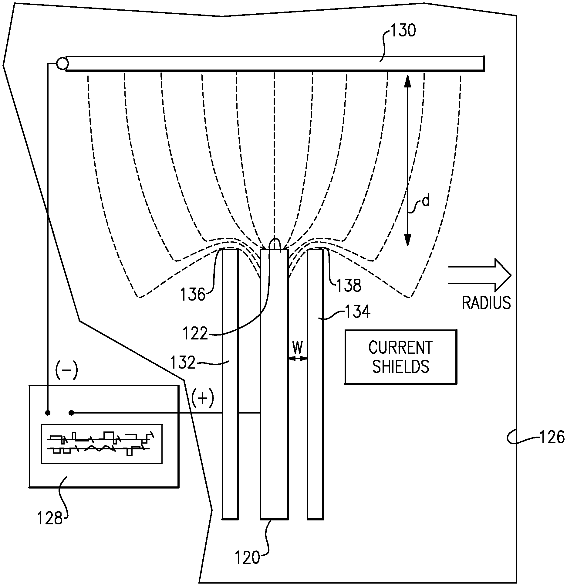
As shown in FIG. 2B, in the finish process, shields 132 and 134 are placed on each side of the workpiece 120. The end 122, which is to form the leading edge 26, is spaced between the shields 132 and 134. A current, which passes between the cathode 130 and the workpiece 120, is deflected around ends 136 and 138 of the shields 132 and 123 and, thus, concentrated at the end 122 of the workpiece 120. In this manner, a curve leading edge 26, such as shown in FIG. 1, is formed.
While the method is shown as two separate steps, in practice, automation techniques may be utilized to have the two happen serially, without any significant down time between the two steps.
A worker of ordinary skill in this art would recognize that by controlling a distance W between the workpiece 120 and the shields 132 and 134 and a distance d between the end 122 and the cathode 130, the extent and shape of the leading edge to be formed can be controlled.
FIG. 3 shows an alternative shield 140, which is not placed parallel to a second shield. Rather, it sits between the end of workpiece 120 and the electrode 130. Shield 140 has a slot or aperture 142 aligned with the end 122 of the workpiece 120, which is to form the leading edge. With this embodiment, the current will again be concentrated at the end 122 to form a leading edge 26.
Generically, the two embodiments could both be said to include the provision of a shield in a current distribution path to concentrate the current distribution on an end of a workpiece.
The trailing edge is formed in a similar manner.
The shields 132, 134 and 140 are all formed of an appropriate material which is generally non-conductive. As an example, an insulator, such as a plastic, may be utilized.
In the FIG. 2B embodiment, the shields 132 and 134 may be parallel.
Although an embodiment of this invention has been disclosed, a worker of ordinary skill in this art would recognize that certain modifications would come within the scope of this invention. For that reason, the following claims should be studied to determine the true scope and content of this invention.
* * * * *
D00000
D00001
D00002
XML
uspto.report is an independent third-party trademark research tool that is not affiliated, endorsed, or sponsored by the United States Patent and Trademark Office (USPTO) or any other governmental organization. The information provided by uspto.report is based on publicly available data at the time of writing and is intended for informational purposes only.
While we strive to provide accurate and up-to-date information, we do not guarantee the accuracy, completeness, reliability, or suitability of the information displayed on this site. The use of this site is at your own risk. Any reliance you place on such information is therefore strictly at your own risk.
All official trademark data, including owner information, should be verified by visiting the official USPTO website at www.uspto.gov. This site is not intended to replace professional legal advice and should not be used as a substitute for consulting with a legal professional who is knowledgeable about trademark law.