Fabric switching
Vobbilisetty , et al.
U.S. patent number 10,673,703 [Application Number 13/098,490] was granted by the patent office on 2020-06-02 for fabric switching. This patent grant is currently assigned to AVAGO TECHNOLOGIES INTERNATIONAL SALES PTE. LIMITED. The grantee listed for this patent is Dilip Chatwani, Suresh Vobbilisetty. Invention is credited to Dilip Chatwani, Suresh Vobbilisetty.


View All Diagrams
| United States Patent | 10,673,703 |
| Vobbilisetty , et al. | June 2, 2020 |
Fabric switching
Abstract
One embodiment of the present invention provides a switch system. The switch includes one or more ports on the switch configured to transmit packets encapsulated based on a first protocol. The switch further includes a control mechanism. During operation, the control mechanism forms a logical switch based on a second protocol, receives an automatically assigned identifier for the logical switch without requiring manual configuration of the identifier, and joins a Ethernet fabric.
| Inventors: | Vobbilisetty; Suresh (San Jose, CA), Chatwani; Dilip (San Jose, CA) | ||||||||||
|---|---|---|---|---|---|---|---|---|---|---|---|
| Applicant: |
|
||||||||||
| Assignee: | AVAGO TECHNOLOGIES INTERNATIONAL
SALES PTE. LIMITED (Singapore, SG) |
||||||||||
| Family ID: | 44858230 | ||||||||||
| Appl. No.: | 13/098,490 | ||||||||||
| Filed: | May 2, 2011 |
Prior Publication Data
| Document Identifier | Publication Date | |
|---|---|---|
| US 20110268120 A1 | Nov 3, 2011 | |
Related U.S. Patent Documents
| Application Number | Filing Date | Patent Number | Issue Date | ||
|---|---|---|---|---|---|
| 61330678 | May 3, 2010 | ||||
| 61334945 | May 14, 2010 | ||||
| 61380819 | Sep 8, 2010 | ||||
| Current U.S. Class: | 1/1 |
| Current CPC Class: | H04L 41/0886 (20130101); H04L 49/357 (20130101); H04L 49/70 (20130101); H04L 45/46 (20130101); H04L 45/245 (20130101); H04L 49/352 (20130101) |
| Current International Class: | H04L 12/24 (20060101); H04L 12/715 (20130101); H04L 12/931 (20130101); H04L 12/709 (20130101) |
References Cited [Referenced By]
U.S. Patent Documents
| 829529 | August 1906 | Keathley |
| 5390173 | February 1995 | Spinney |
| 5802278 | September 1998 | Isfeld |
| 5878232 | March 1999 | Marimuthu |
| 5879173 | March 1999 | Poplawski |
| 5959968 | September 1999 | Chin |
| 5973278 | October 1999 | Wehrill, III |
| 5983278 | November 1999 | Chong |
| 5995262 | November 1999 | Hirota |
| 6041042 | March 2000 | Bussiere |
| 6085238 | July 2000 | Yuasa |
| 6092062 | July 2000 | Lohman |
| 6104696 | August 2000 | Kadambi |
| 6122639 | September 2000 | Babu |
| 6185214 | February 2001 | Schwartz |
| 6185241 | February 2001 | Sun |
| 6295527 | September 2001 | McCormack |
| 6331983 | December 2001 | Haggerty |
| 6438106 | August 2002 | Pillar |
| 6498781 | December 2002 | Bass |
| 6542266 | April 2003 | Phillips |
| 6553029 | April 2003 | Alexander |
| 6571355 | May 2003 | Linnell |
| 6583902 | June 2003 | Yuen |
| 6633761 | October 2003 | Singhal |
| 6636963 | October 2003 | Stein |
| 6771610 | August 2004 | Seaman |
| 6816462 | November 2004 | Booth, III |
| 6870840 | March 2005 | Hill |
| 6873602 | March 2005 | Ambe |
| 6920503 | July 2005 | Nanji |
| 6937576 | August 2005 | DiBenedetto |
| 6956824 | October 2005 | Mark |
| 6957269 | October 2005 | Williams |
| 6975581 | December 2005 | Medina |
| 6975864 | December 2005 | Singhal |
| 7016352 | March 2006 | Chow |
| 7061877 | June 2006 | Gummalla et al. |
| 7062177 | June 2006 | Grivna |
| 7097308 | August 2006 | Kim et al. |
| 7173934 | February 2007 | Lapuh |
| 7197308 | March 2007 | Singhal |
| 7206288 | April 2007 | Cometto |
| 7274694 | September 2007 | Cheng |
| 7310664 | December 2007 | Merchant |
| 7313637 | December 2007 | Tanaka |
| 7315545 | January 2008 | Chowdhury et al. |
| 7316031 | January 2008 | Griffith |
| 7330897 | February 2008 | Baldwin |
| 7380025 | May 2008 | Riggins |
| 7397768 | July 2008 | Betker |
| 7397794 | July 2008 | Lacroute et al. |
| 7430164 | September 2008 | Bare |
| 7453888 | November 2008 | Zabihi |
| 7477894 | January 2009 | Sinha |
| 7480258 | January 2009 | Shuen |
| 7508757 | March 2009 | Ge |
| 7558195 | July 2009 | Kuo |
| 7558273 | July 2009 | Grosser, Jr. |
| 7571447 | August 2009 | Ally |
| 7599901 | October 2009 | Mital |
| 7653056 | January 2010 | Dianes |
| 7688736 | March 2010 | Walsh |
| 7688960 | March 2010 | Aubuchon |
| 7690040 | March 2010 | Frattura |
| 7706255 | April 2010 | Kondrat et al. |
| 7716370 | May 2010 | Devarapalli |
| 7720076 | May 2010 | Dobbins |
| 7729296 | June 2010 | Choudhary |
| 7787480 | August 2010 | Mehta |
| 7792920 | September 2010 | Istvan |
| 7796593 | September 2010 | Ghosh |
| 7801021 | September 2010 | Triantafillis |
| 7808992 | October 2010 | Homchaudhuri |
| 7836332 | November 2010 | Hara |
| 7843906 | November 2010 | Chidambaram et al. |
| 7843907 | November 2010 | Abou-Emara |
| 7860097 | December 2010 | Lovett |
| 7898959 | March 2011 | Arad |
| 7912091 | March 2011 | Krishnan |
| 7924837 | April 2011 | Shabtay |
| 7937438 | May 2011 | Miller |
| 7937756 | May 2011 | Kay |
| 7949638 | May 2011 | Goodson |
| 7957386 | June 2011 | Aggarwal |
| 8014378 | September 2011 | Yoon |
| 8018938 | September 2011 | Fromm |
| 8027354 | September 2011 | Portolani |
| 7945941 | November 2011 | Vobbilisetty |
| 8054832 | November 2011 | Shukla |
| 8068442 | November 2011 | Kompella |
| 8078704 | December 2011 | Lee |
| 8090805 | January 2012 | Chawla |
| 8102781 | January 2012 | Smith |
| 8102791 | January 2012 | Smith |
| 8116307 | February 2012 | Thesayi |
| 8125928 | February 2012 | Mehta |
| 8134922 | March 2012 | Elangovan |
| 8155150 | April 2012 | Chung |
| 8160063 | April 2012 | Maltz |
| 8160080 | April 2012 | Arad |
| 8170038 | May 2012 | Belanger |
| 8175107 | May 2012 | Yalagandula |
| 8095774 | June 2012 | Lambeth |
| 8194674 | June 2012 | Pagel |
| 8195774 | June 2012 | Lambeth |
| 8204061 | June 2012 | Sane |
| 8213313 | July 2012 | Doiron |
| 8213336 | July 2012 | Smith |
| 8230069 | July 2012 | Korupolu |
| 8239960 | August 2012 | Frattura |
| 8249069 | August 2012 | Raman |
| 8270401 | September 2012 | Barnes |
| 8295291 | October 2012 | Ramanathan |
| 8295921 | October 2012 | Ramanathan |
| 8301686 | October 2012 | Appajodu |
| 8339994 | December 2012 | Gnanasekaran |
| 8351352 | January 2013 | Eastlake, III |
| 8369335 | February 2013 | Jha |
| 8369347 | February 2013 | Xiong |
| 8392496 | March 2013 | Linden |
| 8451717 | May 2013 | Srikrishnan |
| 8462774 | June 2013 | Page |
| 8465774 | June 2013 | Page |
| 8467375 | June 2013 | Blair |
| 8520595 | August 2013 | Yadav |
| 8553710 | October 2013 | White |
| 8595479 | November 2013 | Radhakrishnan |
| 8599850 | December 2013 | Jha |
| 8599864 | December 2013 | Chung |
| 8615008 | December 2013 | Natarajan |
| 8619788 | December 2013 | Sankaran |
| 8625616 | January 2014 | Vobbilisetty |
| 8705526 | April 2014 | Hasan |
| 8706905 | April 2014 | McGlaughlin |
| 8717895 | May 2014 | Koponen |
| 8724456 | May 2014 | Hong |
| 8792501 | July 2014 | Rustagi |
| 8798045 | August 2014 | Aybay |
| 8798055 | August 2014 | An |
| 8804732 | August 2014 | Hepting |
| 8804736 | August 2014 | Drake |
| 8806031 | August 2014 | Kondur |
| 8826385 | September 2014 | Congdon |
| 8918631 | December 2014 | Kumar |
| 8937865 | January 2015 | Kumar |
| 8948181 | February 2015 | Kapadia |
| 8971173 | March 2015 | Choudhury |
| 9019976 | April 2015 | Gupta |
| 9178793 | November 2015 | Marlow |
| 9231890 | January 2016 | Vobbilisetty |
| 9350680 | May 2016 | Thayalan |
| 9401818 | July 2016 | Venkatesh |
| 9438447 | September 2016 | Basso |
| 9450870 | September 2016 | Ananthapadmanabha |
| 9524173 | December 2016 | Guntaka |
| 9626255 | April 2017 | Guntaka |
| 9628407 | April 2017 | Guntaka |
| 2001/0005527 | June 2001 | Vaeth |
| 2001/0055274 | December 2001 | Hegge |
| 2002/0019904 | February 2002 | Katz |
| 2002/0021701 | February 2002 | Lavian et al. |
| 2002/0027885 | March 2002 | Ben-Ami |
| 2002/0039350 | April 2002 | Wang |
| 2002/0054593 | May 2002 | Morohashi et al. |
| 2002/0087723 | July 2002 | Williams |
| 2002/0091707 | July 2002 | Keller |
| 2002/0091795 | July 2002 | Yip |
| 2002/0138628 | September 2002 | Tingley |
| 2002/0161867 | October 2002 | Cochran |
| 2003/0026290 | February 2003 | Umayabashi |
| 2003/0041085 | February 2003 | Sato |
| 2003/0093567 | May 2003 | Lolayekar |
| 2003/0097464 | May 2003 | Martinez |
| 2003/0097470 | May 2003 | Lapuh |
| 2003/0123393 | July 2003 | Feuerstraeter |
| 2003/0147385 | August 2003 | Montalvo |
| 2003/0152075 | August 2003 | Hawthorne |
| 2003/0174706 | September 2003 | Shankar |
| 2003/0189905 | October 2003 | Lee |
| 2003/0189930 | October 2003 | Terrell |
| 2003/0208616 | November 2003 | Laing |
| 2003/0216143 | November 2003 | Roese |
| 2003/0223428 | December 2003 | BlanquerGonzalez |
| 2003/0233534 | December 2003 | Bernhard |
| 2004/0001433 | January 2004 | Gram |
| 2004/0003094 | January 2004 | See |
| 2004/0010600 | January 2004 | Baldwin et al. |
| 2004/0088668 | January 2004 | Bornowski |
| 2004/0037295 | February 2004 | Tanaka |
| 2004/0047349 | March 2004 | Fujita |
| 2004/0049699 | March 2004 | Griffith |
| 2004/0057430 | March 2004 | Paavolainen |
| 2004/0081171 | April 2004 | Finn |
| 2004/0088437 | May 2004 | Stimac |
| 2004/0095900 | May 2004 | Siegel |
| 2004/0117508 | June 2004 | Shimizu |
| 2004/0120326 | June 2004 | Yoon |
| 2004/0156313 | August 2004 | Hofmeister et al. |
| 2004/0165595 | August 2004 | Holmgren |
| 2004/0165596 | August 2004 | Holmgren |
| 2004/0205234 | October 2004 | Barrack |
| 2004/0213232 | October 2004 | Regan |
| 2004/0225725 | November 2004 | Enomoto |
| 2004/0243673 | December 2004 | Goyal |
| 2005/0007951 | January 2005 | Lapuh |
| 2005/0025179 | February 2005 | McLaggan |
| 2005/0036488 | February 2005 | Kalkunte |
| 2005/0044199 | February 2005 | Shiga |
| 2005/0074001 | April 2005 | Mattes |
| 2005/0094568 | May 2005 | Judd |
| 2005/0094630 | May 2005 | Valdevit |
| 2005/0108375 | May 2005 | Hallak-Stamler |
| 2005/0111352 | May 2005 | Ho |
| 2005/0122979 | June 2005 | Gross |
| 2005/0152335 | July 2005 | Lodha |
| 2005/0157645 | July 2005 | Rabie et al. |
| 2005/0157751 | July 2005 | Rabie |
| 2005/0169188 | August 2005 | Cometto |
| 2005/0195813 | September 2005 | Ambe |
| 2005/0207423 | September 2005 | Herbst |
| 2005/0213561 | September 2005 | Yao et al. |
| 2005/0220096 | October 2005 | Friskney |
| 2005/0259586 | November 2005 | Hafid |
| 2005/0265330 | December 2005 | Suzuki |
| 2005/0265356 | December 2005 | Kawarai |
| 2005/0278565 | December 2005 | Frattura |
| 2006/0007869 | January 2006 | Hirota |
| 2006/0018302 | January 2006 | Ivaldi |
| 2006/0023707 | February 2006 | Makishima et al. |
| 2006/0029055 | February 2006 | Perera |
| 2006/0034292 | February 2006 | Wakayama |
| 2006/0036648 | February 2006 | Frey |
| 2006/0036765 | February 2006 | Weyman |
| 2006/0039366 | February 2006 | Ghosh |
| 2006/0059163 | March 2006 | Frattura |
| 2006/0062187 | March 2006 | Rune |
| 2006/0072550 | April 2006 | Davis |
| 2006/0083172 | April 2006 | Jordan |
| 2006/0083254 | April 2006 | Ge |
| 2006/0093254 | April 2006 | Ge |
| 2006/0092860 | May 2006 | Higashitaniguchi |
| 2006/0098589 | May 2006 | Kreeger |
| 2006/0126511 | June 2006 | Youn |
| 2006/0140130 | June 2006 | Kalkunte |
| 2006/0155828 | July 2006 | Ikeda |
| 2006/0168109 | July 2006 | Warmenhoven |
| 2006/0184937 | August 2006 | Abels |
| 2006/0206655 | September 2006 | Chappell |
| 2006/0209886 | September 2006 | Silberman |
| 2006/0221960 | October 2006 | Borgione |
| 2006/0227776 | October 2006 | Chandrasekaran |
| 2006/0235995 | October 2006 | Bhatia |
| 2006/0242311 | October 2006 | Mai |
| 2006/0242398 | October 2006 | Fontijn |
| 2006/0245439 | November 2006 | Sajassi |
| 2006/0251067 | November 2006 | DeSanti et al. |
| 2006/0256767 | November 2006 | Suzuki |
| 2006/0265515 | November 2006 | Shiga |
| 2006/0285499 | December 2006 | Tzeng |
| 2006/0291388 | December 2006 | Amdahl |
| 2006/0291480 | December 2006 | Cho |
| 2006/0294413 | December 2006 | Filz |
| 2007/0036178 | February 2007 | Hares |
| 2007/0053294 | March 2007 | Ho |
| 2007/0061817 | March 2007 | Atkinson |
| 2007/0074052 | March 2007 | Hemmah |
| 2007/0081530 | April 2007 | Nomura |
| 2007/0083625 | April 2007 | Chamdani |
| 2007/0086362 | April 2007 | Kato |
| 2007/0094464 | April 2007 | Sharma |
| 2007/0097968 | May 2007 | Du |
| 2007/0098006 | May 2007 | Parry |
| 2007/0110068 | May 2007 | Sekiguchi |
| 2007/0116224 | May 2007 | Burke |
| 2007/0116422 | May 2007 | Burke |
| 2007/0121617 | May 2007 | Kanekar |
| 2007/0130295 | June 2007 | Rastogi |
| 2007/0156659 | July 2007 | Lim |
| 2007/0177525 | August 2007 | Wijnands |
| 2007/0177597 | August 2007 | Ju |
| 2007/0183313 | August 2007 | Narayanan |
| 2007/0183393 | August 2007 | Boyd |
| 2007/0206762 | September 2007 | Chandra |
| 2007/0211712 | September 2007 | Fitch |
| 2007/0220059 | September 2007 | Lu |
| 2007/0226214 | September 2007 | Smits |
| 2007/0230468 | October 2007 | Narayanan |
| 2007/0230472 | October 2007 | Jesuraj |
| 2007/0238343 | October 2007 | Velleca |
| 2007/0258449 | November 2007 | Bennett |
| 2007/0274234 | November 2007 | Kubota |
| 2007/0280223 | December 2007 | Pan |
| 2007/0289017 | December 2007 | Copeland, III |
| 2007/0297406 | December 2007 | Rooholamini |
| 2008/0052487 | February 2008 | Akahane |
| 2008/0056135 | March 2008 | Lee |
| 2008/0056300 | March 2008 | Williams |
| 2008/0057918 | March 2008 | Abrant |
| 2008/0065760 | March 2008 | Damm |
| 2008/0075078 | March 2008 | Watanabe |
| 2008/0080517 | April 2008 | Roy |
| 2008/0095160 | April 2008 | Yadav |
| 2008/0101386 | May 2008 | Gray |
| 2008/0112133 | May 2008 | Torudbakken |
| 2008/0112400 | May 2008 | Dunbar et al. |
| 2008/0133760 | June 2008 | Henricus |
| 2008/0159260 | July 2008 | Vobbilisetty |
| 2008/0159277 | July 2008 | Vobbilisetty |
| 2008/0165705 | July 2008 | Umayabashi |
| 2008/0172492 | July 2008 | Raghunath |
| 2008/0181196 | July 2008 | Regan |
| 2008/0181243 | July 2008 | Vobbilisetty |
| 2008/0186968 | August 2008 | Farinacci |
| 2008/0186981 | August 2008 | Seto |
| 2008/0205377 | August 2008 | Chao |
| 2008/0219172 | September 2008 | Mohan |
| 2008/0225852 | September 2008 | Melman |
| 2008/0225853 | September 2008 | Melman |
| 2008/0228897 | September 2008 | Ko |
| 2008/0240129 | October 2008 | Elmeleegy |
| 2008/0253380 | October 2008 | Cazares |
| 2008/0267179 | October 2008 | Lavigne |
| 2008/0279196 | November 2008 | Friskney |
| 2008/0285458 | November 2008 | Lysne |
| 2008/0285555 | November 2008 | Ogasahara |
| 2008/0288020 | November 2008 | Einav |
| 2008/0298248 | December 2008 | Roeck |
| 2008/0304498 | December 2008 | Jorgensen |
| 2008/0304519 | December 2008 | Koenen |
| 2008/0310342 | December 2008 | Kruys |
| 2009/0022069 | January 2009 | Khan |
| 2009/0024734 | January 2009 | Merbach |
| 2009/0037607 | February 2009 | Farinacci |
| 2009/0037977 | February 2009 | Gai |
| 2009/0041046 | February 2009 | Hirata |
| 2009/0042270 | February 2009 | Shelly |
| 2009/0044270 | February 2009 | Shelly |
| 2009/0052326 | February 2009 | Bergamasco |
| 2009/0067422 | March 2009 | Poppe |
| 2009/0067442 | March 2009 | Killian |
| 2009/0079560 | March 2009 | Fries |
| 2009/0080345 | March 2009 | Gray |
| 2009/0083445 | March 2009 | Ganga |
| 2009/0092042 | April 2009 | Yuhara |
| 2009/0092043 | April 2009 | Lapuh |
| 2009/0094354 | April 2009 | Rastogi |
| 2009/0106298 | April 2009 | Furusho |
| 2009/0106405 | April 2009 | Mazarick |
| 2009/0113408 | April 2009 | Toeroe |
| 2009/0116381 | May 2009 | Kanda |
| 2009/0122700 | May 2009 | Aboba |
| 2009/0129384 | May 2009 | Regan |
| 2009/0129389 | May 2009 | Halna DeFretay |
| 2009/0138577 | May 2009 | Casado |
| 2009/0138752 | May 2009 | Graham |
| 2009/0144720 | June 2009 | Roush |
| 2009/0161584 | June 2009 | Guan |
| 2009/0161670 | June 2009 | Shepherd |
| 2009/0168647 | July 2009 | Holness |
| 2009/0199177 | August 2009 | Edwards |
| 2009/0204965 | August 2009 | Tanaka |
| 2009/0213783 | August 2009 | Moreton |
| 2009/0213867 | August 2009 | Devireddy |
| 2009/0222879 | September 2009 | Kostal |
| 2009/0225752 | September 2009 | Mitsumori |
| 2009/0232031 | September 2009 | Vasseur |
| 2009/0245112 | October 2009 | Okazaki |
| 2009/0245137 | October 2009 | Hares |
| 2009/0245242 | October 2009 | Carlson et al. |
| 2009/0246137 | October 2009 | Hares |
| 2009/0249444 | October 2009 | Macauley |
| 2009/0252049 | October 2009 | Ludwig |
| 2009/0252061 | October 2009 | Small |
| 2009/0252503 | October 2009 | Ishigami |
| 2009/0260083 | October 2009 | Szeto |
| 2009/0279558 | November 2009 | Davis |
| 2009/0279701 | November 2009 | Moisand |
| 2009/0292858 | November 2009 | Lambeth |
| 2009/0316721 | December 2009 | Kanda |
| 2009/0323698 | December 2009 | LeFaucheur |
| 2009/0323708 | December 2009 | Ihle |
| 2009/0327392 | December 2009 | Tripathi |
| 2009/0327462 | December 2009 | Adams |
| 2010/0002382 | January 2010 | Aybay |
| 2010/0027420 | February 2010 | Smith |
| 2010/0027429 | February 2010 | Jorgens |
| 2010/0042869 | February 2010 | Szabo |
| 2010/0046471 | February 2010 | Hattori |
| 2010/0054260 | March 2010 | Pandey |
| 2010/0061269 | March 2010 | Banerjee |
| 2010/0074175 | March 2010 | Banks |
| 2010/0085981 | April 2010 | Gupta |
| 2010/0097941 | April 2010 | Carlson |
| 2010/0103813 | April 2010 | Allan |
| 2010/0103939 | April 2010 | Carlson et al. |
| 2010/0104280 | April 2010 | Carlson |
| 2010/0114818 | May 2010 | Lier |
| 2010/0131636 | May 2010 | Suri |
| 2010/0157844 | June 2010 | Casey |
| 2010/0158024 | June 2010 | Sajassi |
| 2010/0165877 | July 2010 | Shukia |
| 2010/0165995 | July 2010 | Mehta |
| 2010/0168467 | July 2010 | Shukla |
| 2010/0169467 | July 2010 | Shukia |
| 2010/0169948 | July 2010 | Budko |
| 2010/0182920 | July 2010 | Matsuoka |
| 2010/0189119 | July 2010 | Sawada |
| 2010/0192225 | July 2010 | Ma |
| 2010/0195489 | August 2010 | Zhou |
| 2010/0195529 | August 2010 | Liu |
| 2010/0214913 | August 2010 | Kompella |
| 2010/0215042 | August 2010 | Sato |
| 2010/0215049 | August 2010 | Raza |
| 2010/0220724 | September 2010 | Rabie |
| 2010/0226368 | September 2010 | Mack-Crane |
| 2010/0226381 | September 2010 | Mehta |
| 2010/0246388 | September 2010 | Gupta et al. |
| 2010/0246580 | September 2010 | Kaganoi |
| 2010/0254703 | October 2010 | Kirkpatrick |
| 2010/0257263 | October 2010 | Casado |
| 2010/0258263 | October 2010 | Douxchamps |
| 2010/0265849 | October 2010 | Harel |
| 2010/0271960 | October 2010 | Krygowski |
| 2010/0272107 | October 2010 | Papp et al. |
| 2010/0281106 | November 2010 | Ashwood-Smith |
| 2010/0284414 | November 2010 | Gray |
| 2010/0284418 | November 2010 | Gray |
| 2010/0284698 | November 2010 | McColloch |
| 2010/0287262 | November 2010 | Elzur |
| 2010/0287548 | November 2010 | Zhou |
| 2010/0290464 | November 2010 | Assarpour |
| 2010/0290472 | November 2010 | Raman |
| 2010/0290473 | November 2010 | Enduri |
| 2010/0299527 | November 2010 | Arunan |
| 2010/0303071 | December 2010 | Kotalwar |
| 2010/0303075 | December 2010 | Tripathi |
| 2010/0303083 | December 2010 | Belanger |
| 2010/0309820 | December 2010 | Rajagopalan |
| 2010/0309912 | December 2010 | Mehta |
| 2010/0316055 | December 2010 | Belanger |
| 2010/0329110 | December 2010 | Rose |
| 2010/0329265 | December 2010 | Lapuh |
| 2011/0007738 | January 2011 | Berman |
| 2011/0019678 | January 2011 | Mehta |
| 2011/0032945 | February 2011 | Mullooly |
| 2011/0035489 | February 2011 | Shah |
| 2011/0035498 | February 2011 | Shah |
| 2011/0044339 | February 2011 | Kotalwar |
| 2011/0044352 | February 2011 | Chaitou |
| 2011/0051723 | March 2011 | Rabie |
| 2011/0058547 | March 2011 | Waldrop |
| 2011/0064086 | March 2011 | Xiong |
| 2011/0064089 | March 2011 | Xiong |
| 2011/0072208 | March 2011 | Gulati |
| 2011/0085557 | April 2011 | Gnanasekaran |
| 2011/0085560 | April 2011 | Chawla |
| 2011/0085562 | April 2011 | Bao |
| 2011/0085563 | April 2011 | Kotha |
| 2011/0088011 | April 2011 | Ouali |
| 2011/0110266 | May 2011 | Li |
| 2011/0134802 | June 2011 | Rajagopalan |
| 2011/0134803 | June 2011 | Dalvi |
| 2011/0134924 | June 2011 | Hewson |
| 2011/0134925 | June 2011 | Safrai |
| 2011/0142053 | June 2011 | Van Der Merwe |
| 2011/0142062 | June 2011 | Wang |
| 2011/0149526 | June 2011 | Turner |
| 2011/0158113 | June 2011 | Nanda |
| 2011/0161494 | June 2011 | McDysan |
| 2011/0161695 | June 2011 | Okita |
| 2011/0176412 | July 2011 | Stine |
| 2011/0188373 | August 2011 | Saito |
| 2011/0194403 | August 2011 | Sajassi |
| 2011/0194563 | August 2011 | Shen |
| 2011/0225540 | September 2011 | d'Entremont |
| 2011/0228767 | September 2011 | Singla |
| 2011/0228780 | September 2011 | Ashwood-Smith |
| 2011/0231570 | September 2011 | Altekar |
| 2011/0231574 | September 2011 | Saunderson |
| 2011/0235523 | September 2011 | Jha |
| 2011/0243133 | October 2011 | Villait |
| 2011/0243136 | October 2011 | Raman |
| 2011/0246669 | October 2011 | Kanada |
| 2011/0255538 | October 2011 | Srinivasan |
| 2011/0255540 | October 2011 | Mizrahi |
| 2011/0261828 | October 2011 | Smith |
| 2011/0268118 | November 2011 | Schlansker |
| 2011/0268120 | November 2011 | Vobbilisetty |
| 2011/0268125 | November 2011 | Vobbilisetty et al. |
| 2011/0273988 | November 2011 | Tourrilhes |
| 2011/0273990 | November 2011 | Rajagopalan |
| 2011/0274114 | November 2011 | Dhar |
| 2011/0280572 | November 2011 | Vobbilisetty |
| 2011/0286357 | November 2011 | Haris |
| 2011/0286457 | November 2011 | Ee |
| 2011/0286462 | November 2011 | Kompella |
| 2011/0055274 | December 2011 | Hegge |
| 2011/0292947 | December 2011 | Vobbilisetty |
| 2011/0296052 | December 2011 | Guo |
| 2011/0299391 | December 2011 | Vobbilisetty |
| 2011/0299413 | December 2011 | Chatwani |
| 2011/0299414 | December 2011 | Yu |
| 2011/0299527 | December 2011 | Yu |
| 2011/0299528 | December 2011 | Yu |
| 2011/0299531 | December 2011 | Yu |
| 2011/0299532 | December 2011 | Yu |
| 2011/0299533 | December 2011 | Yu |
| 2011/0299534 | December 2011 | Koganti |
| 2011/0299535 | December 2011 | Vobbilisetty |
| 2011/0299536 | December 2011 | Cheng |
| 2011/0317559 | December 2011 | Kern |
| 2011/0317703 | December 2011 | Dunbar et al. |
| 2012/0011240 | January 2012 | Hara |
| 2012/0014261 | January 2012 | Salam |
| 2012/0014387 | January 2012 | Dunbar |
| 2012/0020220 | January 2012 | Sugita |
| 2012/0027017 | February 2012 | Rai |
| 2012/0033663 | February 2012 | Guichard |
| 2012/0033665 | February 2012 | Jacob Da Silva |
| 2012/0033668 | February 2012 | Humphries |
| 2012/0033669 | February 2012 | Mohandas |
| 2012/0033672 | February 2012 | Page |
| 2012/0039163 | February 2012 | Nakajima |
| 2012/0042095 | February 2012 | Kotha |
| 2012/0063363 | March 2012 | Li |
| 2012/0075991 | March 2012 | Sugita |
| 2012/0099567 | April 2012 | Hart |
| 2012/0099602 | April 2012 | Nagapudi |
| 2012/0099863 | April 2012 | Xu |
| 2012/0102160 | April 2012 | Breh |
| 2012/0106339 | May 2012 | Mishra |
| 2012/0117438 | May 2012 | Shaffer |
| 2012/0131097 | May 2012 | Baykal |
| 2012/0131289 | May 2012 | Taguchi |
| 2012/0134266 | May 2012 | Roitshtein |
| 2012/0136999 | May 2012 | Roitshtein |
| 2012/0147740 | June 2012 | Nakash |
| 2012/0158997 | June 2012 | Hsu |
| 2012/0163164 | June 2012 | Terry |
| 2012/0170491 | July 2012 | Kern |
| 2012/0177039 | July 2012 | Berman |
| 2012/0210416 | August 2012 | Mihelich |
| 2012/0221636 | August 2012 | Surtani |
| 2012/0230225 | September 2012 | Matthews |
| 2012/0239918 | September 2012 | Huang |
| 2012/0243359 | September 2012 | Keesara |
| 2012/0243539 | September 2012 | Keesara |
| 2012/0250502 | October 2012 | Brolin |
| 2012/0260079 | October 2012 | Mruthyunjaya |
| 2012/0275297 | November 2012 | Subramanian |
| 2012/0275347 | November 2012 | Banerjee |
| 2012/0278804 | November 2012 | Narayanasamy |
| 2012/0281700 | November 2012 | Koganti |
| 2012/0287785 | November 2012 | Kamble |
| 2012/0294192 | November 2012 | Masood |
| 2012/0294194 | November 2012 | Balasubramanian |
| 2012/0230800 | December 2012 | Kamble |
| 2012/0320800 | December 2012 | Kamble |
| 2012/0320926 | December 2012 | Kamath et al. |
| 2012/0327766 | December 2012 | Tsai et al. |
| 2012/0327937 | December 2012 | Melman et al. |
| 2013/0003535 | January 2013 | Sarwar |
| 2013/0003549 | January 2013 | Matthews |
| 2013/0003608 | January 2013 | Lei |
| 2013/0003737 | January 2013 | Sinicrope |
| 2013/0003738 | January 2013 | Koganti |
| 2013/0003747 | January 2013 | Raman |
| 2013/0016606 | January 2013 | Cirkovic |
| 2013/0028072 | January 2013 | Addanki |
| 2013/0034015 | February 2013 | Jaiswal |
| 2013/0034021 | February 2013 | Jaiswal |
| 2013/0034094 | February 2013 | Cardona |
| 2013/0044629 | February 2013 | Biswas |
| 2013/0058354 | March 2013 | Casado |
| 2013/0066947 | March 2013 | Ahmad |
| 2013/0067466 | March 2013 | Combs |
| 2013/0070762 | March 2013 | Adams |
| 2013/0083693 | April 2013 | Himura |
| 2013/0097345 | April 2013 | Munoz |
| 2013/0114595 | May 2013 | Mack-Crane et al. |
| 2013/0121142 | May 2013 | Bai |
| 2013/0124707 | May 2013 | Ananthapadmanabha |
| 2013/0124750 | May 2013 | Anumala |
| 2013/0127848 | May 2013 | Joshi |
| 2013/0132296 | May 2013 | Manfred |
| 2013/0135811 | May 2013 | Dunwoody |
| 2013/0136123 | May 2013 | Ge |
| 2013/0145008 | June 2013 | Kannan |
| 2013/0148546 | June 2013 | Eisenhauer |
| 2013/0148663 | June 2013 | Xiong |
| 2013/0156425 | June 2013 | Kirkpatrick |
| 2013/0163591 | June 2013 | Shukla |
| 2013/0194914 | August 2013 | Agarwal |
| 2013/0201992 | August 2013 | Masaki |
| 2013/0215754 | August 2013 | Tripathi |
| 2013/0219473 | August 2013 | Schaefer |
| 2013/0223221 | August 2013 | Xu |
| 2013/0223438 | August 2013 | Tripathi |
| 2013/0223449 | August 2013 | Koganti |
| 2013/0238802 | September 2013 | Sarikaya |
| 2013/0250947 | September 2013 | Zheng |
| 2013/0250951 | September 2013 | Koganti |
| 2013/0250958 | September 2013 | Watanabe |
| 2013/0259037 | October 2013 | Natarajan |
| 2013/0266015 | October 2013 | Qu |
| 2013/0268590 | October 2013 | Mahadevan |
| 2013/0272135 | October 2013 | Leong |
| 2013/0294451 | November 2013 | Li |
| 2013/0297757 | November 2013 | Han |
| 2013/0301425 | November 2013 | Chandra |
| 2013/0301642 | November 2013 | Radhakrishnan et al. |
| 2013/0308492 | November 2013 | Baphna |
| 2013/0308641 | November 2013 | Ackley |
| 2013/0308647 | November 2013 | Rosset |
| 2013/0315125 | November 2013 | Ravishankar |
| 2013/0315246 | November 2013 | Zhang |
| 2013/0315586 | November 2013 | Kipp |
| 2013/0322427 | December 2013 | Stiekes |
| 2013/0329605 | December 2013 | Nakil |
| 2013/0332660 | December 2013 | Talagala |
| 2013/0336104 | December 2013 | Talla |
| 2013/0346583 | December 2013 | Low |
| 2014/0010239 | January 2014 | Xu |
| 2014/0013324 | January 2014 | Zhang |
| 2014/0019608 | January 2014 | Kawakami |
| 2014/0019639 | January 2014 | Ueno |
| 2014/0025736 | January 2014 | Wang |
| 2014/0029412 | January 2014 | Janardhanan |
| 2014/0029419 | January 2014 | Jain |
| 2014/0044126 | February 2014 | Sabhanatarajan et al. |
| 2014/0050223 | February 2014 | Foo |
| 2014/0056298 | February 2014 | Vobbilisetty |
| 2014/0059225 | February 2014 | Gasparakis |
| 2014/0064056 | March 2014 | Sakata |
| 2014/0071987 | March 2014 | Janardhanan |
| 2014/0086253 | March 2014 | Yong |
| 2014/0092738 | April 2014 | Grandhi |
| 2014/0105034 | April 2014 | Sun |
| 2014/0112122 | April 2014 | Kapadia |
| 2014/0140243 | May 2014 | Ashwood-Smith |
| 2014/0157251 | June 2014 | Hocker |
| 2014/0169368 | June 2014 | Grover |
| 2014/0188996 | July 2014 | Lie |
| 2014/0192804 | July 2014 | Ghanwani |
| 2014/0195695 | July 2014 | Okita |
| 2014/0241147 | August 2014 | Rajagopalan |
| 2014/0258446 | September 2014 | Bursell |
| 2014/0269701 | September 2014 | Kaushik |
| 2014/0269709 | September 2014 | Benny |
| 2014/0269720 | September 2014 | Srinivasan |
| 2014/0269733 | September 2014 | Venkatesh |
| 2014/0298091 | October 2014 | Carlen |
| 2014/0348168 | November 2014 | Singh |
| 2014/0355477 | December 2014 | Moopath |
| 2014/0362854 | December 2014 | Addanki |
| 2014/0362859 | December 2014 | Addanki |
| 2014/0376550 | December 2014 | Khan |
| 2015/0009992 | January 2015 | Zhang |
| 2015/0010007 | January 2015 | Matsuhira |
| 2015/0016300 | January 2015 | Devireddy |
| 2015/0030031 | January 2015 | Zhou |
| 2015/0092593 | April 2015 | Kompella |
| 2015/0103826 | April 2015 | Davis |
| 2015/0110111 | April 2015 | Song |
| 2015/0110487 | April 2015 | Fenkes |
| 2015/0117256 | April 2015 | Sabaa |
| 2015/0117454 | April 2015 | Koponen |
| 2015/0127618 | May 2015 | Alberti |
| 2015/0139234 | May 2015 | Hu |
| 2015/0143369 | May 2015 | Zheng |
| 2015/0172098 | June 2015 | Agarwal |
| 2015/0188753 | July 2015 | Anumala |
| 2015/0188770 | July 2015 | Naiksatam |
| 2015/0195093 | July 2015 | Ramasubramani |
| 2015/0222506 | August 2015 | Kizhakkiniyil |
| 2015/0248298 | September 2015 | Gavrilov |
| 2015/0263897 | September 2015 | Ganichev |
| 2015/0263899 | September 2015 | Tubaltsev |
| 2015/0263991 | September 2015 | MacChiano |
| 2015/0281066 | October 2015 | Koley |
| 2015/0301901 | October 2015 | Rath |
| 2015/0347468 | December 2015 | Bester |
| 2016/0072899 | March 2016 | Tung |
| 2016/0087885 | March 2016 | Tripathi |
| 2016/0139939 | May 2016 | Bosch |
| 2016/0182458 | June 2016 | Shatzkamer |
| 2016/0212040 | July 2016 | Bhagavathiperumal |
| 2016/0344640 | November 2016 | Soderlund |
| 2017/0012880 | January 2017 | Yang |
| 2017/0026197 | January 2017 | Venkatesh |
| 2017/0097841 | April 2017 | Chang |
| 2017/0134266 | May 2017 | Venkata |
| 2018/0013614 | January 2018 | Vobbilisetty |
| 1735062 | Feb 2006 | CN | |||
| 1777149 | May 2006 | CN | |||
| 101064682 | Oct 2007 | CN | |||
| 101459618 | Jun 2009 | CN | |||
| 101471899 | Jul 2009 | CN | |||
| 101548511 | Sep 2009 | CN | |||
| 101645880 | Feb 2010 | CN | |||
| 102098237 | Jun 2011 | CN | |||
| 102148749 | Aug 2011 | CN | |||
| 102301663 | Dec 2011 | CN | |||
| 102349268 | Feb 2012 | CN | |||
| 102378176 | Mar 2012 | CN | |||
| 102404181 | Apr 2012 | CN | |||
| 102415065 | Apr 2012 | CN | |||
| 102415065 | Apr 2012 | CN | |||
| 102801599 | Nov 2012 | CN | |||
| 102801599 | Nov 2012 | CN | |||
| 102088388 | Apr 2014 | CN | |||
| 0579567 | May 1993 | EP | |||
| 0579567 | Jan 1994 | EP | |||
| 0993156 | Apr 2000 | EP | |||
| 0993156 | Dec 2000 | EP | |||
| 1398920 | Mar 2004 | EP | |||
| 1398920 | Mar 2004 | EP | |||
| 1916807 | Apr 2008 | EP | |||
| 2001167 | Dec 2008 | EP | |||
| 2854352 | Apr 2015 | EP | |||
| 2874359 | May 2015 | EP | |||
| 2008056838 | May 2008 | WO | |||
| 2009042919 | Apr 2009 | WO | |||
| 2010111142 | Sep 2010 | WO | |||
| 2010111142 | Sep 2010 | WO | |||
| 2011132568 | Oct 2011 | WO | |||
| 2011140028 | Nov 2011 | WO | |||
| 2011140028 | Nov 2011 | WO | |||
| 2012033663 | Mar 2012 | WO | |||
| 2012093429 | Jul 2012 | WO | |||
| 2014031781 | Feb 2014 | WO | |||
Other References
|
US. Appl. No. 12/312,903 Office Action dated Jun. 13, 2013. cited by applicant . U.S. Appl. No. 13/365,808 Office Action dated Jul. 18, 2013. cited by applicant . U.S. Appl. No. 13/365,993 Office Action dated Jul. 23, 2013. cited by applicant . U.S. Appl. No. 13/092,873 Office Action dated Jun. 19, 2013. cited by applicant . U.S. Appl. No. 13/184,526 Office Action dated May 22, 2013. cited by applicant . U.S. Appl. No. 13/184,526 Office Action dated Jan. 28, 2013. cited by applicant . U.S. Appl. No. 13/050,102 Office Action dated May 16, 2013. cited by applicant . U.S. Appl. No. 13/050,102 Office Action dated Oct. 26, 2012. cited by applicant . U.S. Appl. No. 13/044,301 Office Action dated Feb. 22, 2013. cited by applicant . U.S. Appl. No. 13/044,301 Office Action dated Jun. 11, 2013. cited by applicant . U.S. Appl. No. 13/030,688 Office Action dated Apr. 25, 2013. cited by applicant . U.S. Appl. No. 13/030,806 Office Action dated Dec. 3, 2012. cited by applicant . U.S. Appl. No. 13/030,806 Office Action dated Jun. 11, 2013. cited by applicant . U.S. Appl. No. 13/098,360 Office Action dated May 31, 2013. cited by applicant . U.S. Appl. No. 13/092,864 Office Action dated Sep. 19, 2012. cited by applicant . U.S. Appl. No. 12/950,968 Office Action dated Jun. 7, 2012. cited by applicant . U.S. Appl. No. 12/950,968 Office Action dated Jan. 4, 2013. cited by applicant . U.S. Appl. No. 13/092,877 Office Action dated Mar. 4, 2013. cited by applicant . U.S. Appl. No. 12/950,974 Office Action dated Dec. 20, 2012. cited by applicant . U.S. Appl. No. 12/950,974 Office Action dated May 24, 2012. cited by applicant . U.S. Appl. No. 13/092,752 Office Action dated Feb. 5, 2013. cited by applicant . U.S. Appl. No. 13/092,752 Office Action dated Jul. 18, 2013. cited by applicant . U.S. Appl. No. 13/092,701 Office Action dated Jan. 28, 2013. cited by applicant . U.S. Appl. No. 13/092,701 Office Action dated Jul. 3, 2013. cited by applicant . U.S. Appl. No. 13/092,460 Office Action dated Jun. 21, 2013. cited by applicant . U.S. Appl. No. 13/042,259 Office Action dated Mar. 18, 2013. cited by applicant . U.S. Appl. No. 13/042,259 Office Action dated Jul. 31, 2013. cited by applicant . U.S. Appl. No. 13/092,580 Office Action dated Jun. 10, 2013. cited by applicant . U.S. Appl. No. 13/092,724 Office Action dated Jul. 16, 2013. cited by applicant . U.S. Appl. No. 13/092,724 Office Action dated Feb. 5, 2013. cited by applicant . U.S. Appl. No. 13/098,490 Office Action dated Dec. 21, 2012. cited by applicant . U.S. Appl. No. 13/098,490 Office Action dated Jul. 9, 2013. cited by applicant . U.S. Appl. No. 13/087,239 Office Action dated May 22, 2013. cited by applicant . U.S. Appl. No. 13/087,239 Office Action dated Dec. 5, 2012. cited by applicant . U.S. Appl. No. 12/725,249 Office Action dated Apr. 26, 2013. cited by applicant . U.S. Appl. No. 12/725,249 Office Action dated Sep. 12, 2012. cited by applicant . Office Action for U.S. Appl. No. 13/092,887, dated Jan. 6, 2014. cited by applicant . Brocade Unveils "The Effortless Network", http://newsroom.brocade.com/press-releases/brocade-unveils-the-effortless- -network-nasdaq-brcd-0859535, 2012. cited by applicant . Foundry FastIron Configuration Guide, Software Release FSX 04.2.00b, Software Release FWS 04.3.00, Software Release FGS 05.0.00a, Sep. 26, 2008. cited by applicant . FastIron and TurboIron 24X Configuration Guide Supporting FSX 05.1.00 for FESX, FWSX, and FSX; FGS 04.3.03 for FGS, FLS and FWS; FGS 05.0.02 for FGS-STK and FLS-STK, FCX 06.0.00 for FCX; and TIX 04.1.00 for TI24X, Feb. 16, 2010. cited by applicant . FastIron Configuration Guide Supporting Ironware Software Release 07.0.00, Dec. 18, 2009. cited by applicant . "The Effortless Network: HyperEdge Technology for the Campus LAN", 2012. cited by applicant . Narten, T. et al. "Problem Statement: Overlays for Network Virtualization", draft-narten-nvo3-overlay-problem-statement-01, Oct. 31, 2011. cited by applicant . Knight, Paul et al., "Layer 2 and 3 Virtual Private Networks: Taxonomy, Technology, and Standardization Efforts", IEEE Communications Magazine, Jun. 2004. cited by applicant . "An Introduction to Brocade VCS Fabric Technology", BROCADE white paper, http://community.brocade.com/docs/DOC-2954, Dec. 3, 2012. cited by applicant . Kreeger, L. et al., "Network Virtualization Overlay Control Protocol Requirements", Draft-kreeger-nvo3-overlay-cp-00, Jan. 30, 2012. cited by applicant . Knight, Paul et al., "Network based IP VPN Architecture using Virtual Routers", May 2003. cited by applicant . Louati, Wajdi et al., "Network-based virtual personal overlay networks using programmable virtual routers", IEEE Communications Magazine, Jul. 2005. cited by applicant . U.S. Appl. No. 13/092,877 Office Action dated Sep. 5, 2013. cited by applicant . U.S. Appl. No. 13/044,326 Office Action dated Oct. 2, 2013. cited by applicant . Zhai F. Hu et al. "RBridge: Pseudo-Nickname; draft-hu-trill-pseudonode-nickname-02.txt", May 15, 2012. cited by applicant . Huang, Nen-Fu et al., "An Effective Spanning Tree Algorithm for a Bridged LAN", Mar. 16, 1992. cited by applicant . Office Action dated Jun. 6, 2014, U.S. Appl. No. 13/669,357, filed Nov. 5, 2012. cited by applicant . Office Action dated Feb. 20, 2014, U.S. Appl. No. 13/598,204, filed Aug. 29, 2012. cited by applicant . Office Action dated May 14, 2014, U.S. Appl. No. 13/533,843, filed Jun. 26, 2012. cited by applicant . Office Action dated May 9, 2014, U.S. Appl. No. 13/484,072, filed May 30, 2012. cited by applicant . Office Action dated Feb. 28, 2014, U.S. Appl. No. 13/351,513, filed Jan. 17, 2012. cited by applicant . Office Action dated Jun. 18, 2014, U.S. Appl. No. 13/440,861, filed Apr. 5, 2012. cited by applicant . Office Action dated Mar. 6, 2014, U.S. Appl. No. 13/425,238, filed Mar. 20, 2012. cited by applicant . Office Action dated Apr. 22, 2014, U.S. Appl. No. 13/030,806, filed Feb. 18, 2011. cited by applicant . Office Action dated Jun. 20, 2014, U.S. Appl. No. 13/092,877, filed Apr. 22, 2011. cited by applicant . Office Action dated Apr. 9, 2014, U.S. Appl. No. 13/092,752, filed Apr. 22, 2011. cited by applicant . Office Action dated Mar. 26, 2014, U.S. Appl. No. 13/092,701, filed Apr. 22, 2011. cited by applicant . Office Action dated Mar. 14, 2014, U.S. Appl. No. 13/092,460, filed Apr. 22, 2011. cited by applicant . Office Action dated Apr. 9, 2014, U.S. Appl. No. 13/092,724, filed Apr. 22, 2011. cited by applicant . "Switched Virtual Internetworking moved beyond bridges and routers", 8178 Data Communications Sep. 23, 1994, No. 12, New York. cited by applicant . S. Night et al., "Virtual Router Redundancy Protocol", Network Working Group, XP-002135272, Apr. 1998. cited by applicant . Eastlake 3rd., Donald et al., "RBridges: TRILL Header Options", Draft-ietf-trill-rbridge-options-00.txt, Dec. 24, 2009. cited by applicant . J. Touch, et al., "Transparent Interconnection of Lots of Links (TRILL): Problem and Applicability Statement", May 2009. cited by applicant . Perlman, Radia et al., "RBridge VLAN Mapping", Draft-ietf-trill-rbridge-vlan-mapping-01.txt, Dec. 4, 2009. cited by applicant . Brocade Fabric OS (FOS) 6.2 Virtual Fabrics Feature Frequently Asked Questions. cited by applicant . Perlman, Radia "Challenges and Opportunities in the Design of TRILL: a Routed layer 2 Technology", XP-002649647, 2009. cited by applicant . Nadas, S. et al., "Virtual Router Redundancy Protocol (VRRP) Version 3 for IPv4 and IPv6", Mar. 2010. cited by applicant . Perlman, Radia et al., "RBridges: Base Protocol Specification", draft-ietf-trill-rbridge-protocol-16.txt, Mar. 3, 2010. cited by applicant . Christensen, M. et al., "Considerations for Internet Group Management Protocol (IGMP) and Multicast Listener Discovery (MLD) Snooping Switches", May 2006. cited by applicant . Lapuh, Roger et al., "Split Multi-link Trunking (SMLT)", Oct. 2002. cited by applicant . Lapuh, Roger et al., "Split Multi-link Trunking (SMLT) draft-lapuh-network-smlt-08", 2008. cited by applicant . `RBridges: Base Protocol Specification`, IETF Draft, Perlman et al., Jun. 26, 2009. cited by applicant . Brocade `An Introduction to Brocade VCS Fabric Technology`, Dec. 3, 2012. cited by applicant . Lapuh, Roger et al., `Split Multi-link Trunking (SMLT) draft-lapuh-network-smlt-08`, Jan. 2009. cited by applicant . Office Action for U.S. Appl. No. 13/030,688, filed Feb. 18, 2011, dated Jul. 17, 2014. cited by applicant . Office Action for U.S. Appl. No. 13/042,259, filed Mar. 7, 2011, from Jaroenchonwanit, Bunjob, dated Jan. 16, 2014. cited by applicant . Office Action for U.S. Appl. No. 13/365,993, filed Feb. 3, 2012, from Cho, Hong Sol., dated Jul. 23, 2013. cited by applicant . Office Action for U.S. Appl. No. 13/030,806, filed Feb. 18, 2011, dated Dec. 3, 2012. cited by applicant . Office Action for U.S. Appl. No. 13/312,903, filed Dec. 6, 2011, dated Jun. 13, 2013. cited by applicant . Office Action for U.S. Appl. No. 13/087,239, filing Apr. 14, 2011, dated Dec. 5, 2012. cited by applicant . Office action dated Apr. 26, 2012, U.S. Appl. No. 12/725,249, filed Mar. 16, 2010. cited by applicant . Office action dated Sep. 12, 2012, U.S. Appl. No. 12/725,249, filed Mar. 16, 2010. cited by applicant . Office action dated Dec. 21, 2012, U.S. Appl. No. 13/098,490, filed May 2, 2011. cited by applicant . Office action dated Mar. 27, 2014, U.S. Appl. No. 13/098,490, filed May 2, 2011. cited by applicant . Office action dated Jul. 9, 2013, U.S. Appl. No. 13/098,490, filed May 2, 2011. cited by applicant . Office action dated May 22, 2013, U.S. Appl. No. 13/087,239, filed Apr. 14, 2011. cited by applicant . Office action dated Dec. 5, 2012, U.S. Appl. No. 13/087,239, filed Apr. 14, 2011. cited by applicant . Office action dated Feb. 5, 2013, U.S. Appl. No. 13/092,724, filed Apr. 22, 2011. cited by applicant . Office action dated Jun. 10, 2013, U.S. Appl. No. 13/092,580, filed Apr. 22, 2011. cited by applicant . Office action dated Mar. 18, 2013, U.S. Appl. No. 13/042,259, filed Mar. 7, 2011. cited by applicant . Office action dated Aug. 29, 2014, U.S. Appl. No. 13/042,259, filed Mar. 7, 2011. cited by applicant . Office action dated Jun. 21, 2013, U.S. Appl. No. 13/092,460, filed Apr. 22, 2011. cited by applicant . Office action dated Jan. 28, 2013, U.S. Appl. No. 13/092,701, filed Apr. 22, 2011. cited by applicant . Office action dated Jul. 3, 2013, U.S. Appl. No. 13/092,701, filed Apr. 22, 2011. cited by applicant . Office action dated Jul. 18, 2013, U.S. Appl. No. 13/092,752, filed Apr. 22, 2011. cited by applicant . Office action dated Dec. 20, 2012, U.S. Appl. No. 12/950,974, filed Nov. 19, 2010. cited by applicant . Office action dated May 24, 2012, U.S. Appl. No. 12/950,974, filed Nov. 19, 2010. cited by applicant . Office action dated Sep. 5, 2013, U.S. Appl. No. 13/092,877, filed Apr. 22, 2011. cited by applicant . Office action dated Mar. 4, 2013, U.S. Appl. No. 13/092,877, filed Apr. 22, 2011. cited by applicant . Office action dated Jan. 4, 2013, U.S. Appl. No. 12/950,968, filed Nov. 19, 2010. cited by applicant . Office action dated Jun. 7, 2012, U.S. Appl. No. 12/950,968, filed Nov. 19, 2010. cited by applicant . Office action dated Sep. 19, 2012, U.S. Appl. No. 13/092,864, filed Apr. 22, 2011. cited by applicant . Office action dated May 31, 2013, U.S. Appl. No. 13/098,360, filed Apr. 29, 2011. cited by applicant . Office action dated Dec. 3, 2012, U.S. Appl. No. 13/030,806, filed Feb. 18, 2011. cited by applicant . Office action dated Jun. 11, 2013, U.S. Appl. No. 13/030,806, filed Feb. 18, 2011. cited by applicant . Office action dated Apr. 25, 2013, U.S. Appl. No. 13/030,688, filed Feb. 18, 2011. cited by applicant . Office action dated Feb. 22, 2013, U.S. Appl. No. 13/044,301, filed Mar. 9, 2011. cited by applicant . Office action dated Jun. 11, 2013, U.S. Appl. No. 13/044,301, filed Mar. 9, 2011. cited by applicant . Office action dated Oct. 26, 2012, U.S. Appl. No. 13/050,102, filed Mar. 17, 2011. cited by applicant . Office action dated May 16, 2013, U.S. Appl. No. 13/050,102, filed Mar. 17, 2011. cited by applicant . Office action dated Aug. 4, 2014, U.S. Appl. No. 13/050,102, filed Mar. 17, 2011. cited by applicant . Office action dated Jan. 28, 2013, U.S. Appl. No. 13/148,526, filed Jul. 16, 2011. cited by applicant . Office action dated May 22, 2013, U.S. Appl. No. 13/148,526, filed Jul. 16, 2011. cited by applicant . Office action dated Aug. 21, 2014, U.S. Appl. No. 13/184,526, filed Jul. 16, 2011. cited by applicant . Office action dated Jun. 19, 2013, U.S. Appl. No. 13/092,873, filed Apr. 22, 2011. cited by applicant . Office action dated Jul. 18, 2013, U.S. Appl. No. 13/365,808, filed Feb. 3, 2012. cited by applicant . Office action dated Jun. 13, 2013, U.S. Appl. No. 13/312,903, filed Dec. 6, 2011. cited by applicant . Office Action for U.S. Appl. No. 13/351,513, filed Jan. 17, 2012, dated Feb. 28, 2014. cited by applicant . Office Action for U.S. Appl. No. 13/098,490, filed May 2, 2011, dated Mar. 27, 2014. cited by applicant . Office Action for U.S. Appl. No. 13/092,873, filed Apr. 22, 2011, dated Nov. 29, 2013. cited by applicant . Office Action for U.S. Appl. No. 13/184,526, filed Jul. 16, 2011, dated Dec. 2, 2013. cited by applicant . Office Action for U.S. Appl. No. 13/598,204, filed Aug. 29, 2012, dated Feb. 20, 2014. cited by applicant . Office Action for U.S. Appl. No. 13/044,326, filed Mar. 9, 2011, dated Jul. 7, 2014. cited by applicant . Office Action for U.S. Appl. No. 13/092,752, filed Apr. 22, 2011, dated Apr. 9, 2014. cited by applicant . Office Action for U.S. Appl. No. 13/092,873, filed Apr. 22, 2011, dated Jul. 25, 2014. cited by applicant . Office Action for U.S. Appl. No. 13/092,877, filed Apr. 22, 2011, dated Jun. 20, 2014. cited by applicant . Office Action for U.S. Appl. No. 13/312,903, filed Dec. 6, 2011, dated Aug. 7, 2014. cited by applicant . Office Action for U.S. Appl. No. 13/351,513, filed Jan. 17, 2012, dated Jul. 24, 2014. cited by applicant . Office Action for U.S. Appl. No. 13/425,238, filed Mar. 20, 2012, dated Mar. 6, 2014. cited by applicant . Office Action for U.S. Appl. No. 13/556,061, filed Jul. 23, 2012, dated Jun. 6, 2014. cited by applicant . Office Action for U.S. Appl. No. 13/742,207 dated Jul. 24, 2014, filed Jan. 15, 2013. cited by applicant . Office Action for U.S. Appl. No. 13/950,974, filed Nov. 19, 2010, dated Dec. 2, 2012. cited by applicant . TRILL Working Group Internet-Draft Intended status: Proposed Standard RBridges: Base Protocol Specificaiton Mar. 3, 2010. cited by applicant . Office action dated Aug. 14, 2014, U.S. Appl. No. 13/092,460, filed Apr. 22, 2011. cited by applicant . Office action dated Jul. 7, 2014, for U.S. Appl. No. 13/044,326, filed Mar. 9, 2011. cited by applicant . Office Action dated Dec. 19, 2014, for U.S. Appl. No. 13/044,326, filed Mar. 9, 2011. cited by applicant . Office Action for U.S. Appl. No. 13/092,873, filed Apr. 22, 2011, dated Nov. 7, 2014. cited by applicant . Office Action for U.S. Appl. No. 13/092,877, filed Apr. 22, 2011, dated Nov. 10, 2014. cited by applicant . Office Action for U.S. Appl. No. 13/157,942, filed Jun. 10, 2011. cited by applicant . Mckeown, Nick et al. "OpenFlow: Enabling Innovation in Campus Networks", Mar. 14, 2008, www.openflow.org/documents/openflow-wp-latest.pdf. cited by applicant . Office Action for U.S. Appl. No. 13/044,301, dated Mar. 9, 2011. cited by applicant . Office Action for U.S. Appl. No. 13/184,526, filed Jul. 16, 2011, dated Jan. 5, 2015. cited by applicant . Office Action for U.S. Appl. No. 13/598,204, filed Aug. 29, 2012, dated Jan. 5, 2015. cited by applicant . Office Action for U.S. Appl. No. 13/669,357, filed Nov. 5, 2012, dated Jan. 30, 2015. cited by applicant . Office Action for U.S. Appl. No. 13/851,026, filed Mar. 26, 2013, dated Jan. 30, 2015. cited by applicant . Office Action for U.S. Appl. No. 13/786,328, filed Mar. 5, 2013, dated Mar. 13, 2015. cited by applicant . Office Action for U.S. Appl. No. 13/092,460, filed Apr. 22, 2011, dated Mar. 13, 2015. cited by applicant . Office Action for U.S. Appl. No. 13/425,238, dated Mar. 12, 2015. cited by applicant . Office Action for U.S. Appl. No. 13/092,752, filed Apr. 22, 2011, dated Feb. 27, 2015. cited by applicant . Office Action for U.S. Appl. No. 13/042,259, filed Mar. 7, 2011, dated Feb. 23, 2015. cited by applicant . Office Action for U.S. Appl. No. 13/044,301, filed Mar. 9, 2011, dated Jan. 29, 2015. cited by applicant . Office Action for U.S. Appl. No. 13/050,102, filed Mar. 17, 2011, dated Jan. 26, 2015. cited by applicant . Office action dated Oct. 2, 2014, for U.S. Appl. No. 13/092,752, filed Apr. 22, 2011. cited by applicant . Kompella, Ed K. et al., `Virtual Private LAN Service (VPLS) Using BGP for Auto-Discovery and Signaling` Jan. 2007. cited by applicant . Rosen, E. et al., "BGP/MPLS VPNs", Mar. 1999. cited by applicant . Office Action for U.S. Appl. No. 14/662,095, dated Mar. 24, 2017. cited by applicant . Office Action for U.S. Appl. No. 15/005,967, dated Mar. 31, 2017. cited by applicant . Office Action for U.S. Appl. No. 15/215,377, dated Apr. 7, 2017. cited by applicant . Office Action for U.S. Appl. No. 13/098,490, dated Apr. 6, 2017. cited by applicant . Office Action for U.S. Appl. No. 14/662,092, dated Mar. 29, 2017. cited by applicant . Office Action for U.S. Appl. No. 14/817,097, dated May 4, 2017. cited by applicant . Office Action for U.S. Appl. No. 14/872,966, dated Apr. 20, 2017. cited by applicant . Office Action for U.S. Appl. No. 14/680,915, dated May 3, 2017. cited by applicant . Office Action for U.S. Appl. No. 14/792,166, dated Apr. 26, 2017. cited by applicant . Office Action for U.S. Appl. No. 14/660,803, dated May 17, 2017. cited by applicant . Office Action for U.S. Appl. No. 14/488,173, dated May 12, 2017. cited by applicant . Office Action for U.S. Appl. No. 13/288,822, dated May 26, 2017. cited by applicant . Office Action for U.S. Appl. No. 14/329,447, dated Jun. 8, 2017. cited by applicant . Office Action for U.S. Appl. No. 14/510,913, dated Jun. 30, 2017. cited by applicant . Office Action for U.S. Appl. No. 15/005,946, dated Jul. 14, 2017. cited by applicant . Office Action for U.S. Appl. No. 13/092,873, dated Jul. 19, 2017. cited by applicant . Office Action for U.S. Appl. No. 15/047,539, dated Aug. 7, 2017. cited by applicant . Office Action for U.S. Appl. No. 14/830,035, dated Aug. 28, 2017. cited by applicant . Office Action for U.S. Appl. No. 13/098,490, dated Aug. 24, 2017. cited by applicant . Office Action for U.S. Appl. No. 13/786,328, dated Aug. 21, 2017. cited by applicant . Office Action for U.S. Appl. No. 14/216,292, dated Oct. 6, 2017. cited by applicant . Office Action dated Oct. 25, 2017, U.S. Appl. No. 14/867,865, filed Sep. 28, 2015. cited by applicant . Office action dated Oct. 26, 2017, U.S. Appl. No. 14/817,097, filed Aug. 3, 2015. cited by applicant . Office Action dated Mar. 20, 2018, U.S. Appl. No. 14/867,865, filed Sep. 28, 2015. cited by applicant . Office Action dated Jun. 13, 2018, U.S. Appl. No. 13/786,328, filed Mar. 5, 2013. cited by applicant . IEEE et al., "Amendment to Carrier Sense Multiple Access with Collision Detection (CSMA/CD) Access Method and Physical Layer Specifications--Aggregation of Multiple Link Segments", Mar. 30, 2000, IEEE Computer Society, IEEE Std 802.3ad-2000, pp. 116-117. cited by applicant . Office Action dated Jul. 13, 2018, U.S. Appl. No. 15/402,924, filed Jul. 13, 2018. cited by applicant . Office Action dated Jul. 24, 2018, U.S. Appl. No. 14/799,371, filed Jul. 24, 2018. cited by applicant . Office Action dated Jun. 18, 215, U.S. Appl. No. 13/098,490, filed May 2, 2011. cited by applicant . Office Action dated Jun. 16, 2015, U.S. Appl. No. 13/048,817, filed Mar. 15, 2011. cited by applicant . Touch, J. et al., `Transparent Interconnection of Lots of Links (TRILL): Problem and Applicability Statement`, May 2009, Network Working Group, pp. 1-17. cited by applicant . Office Action dated Jul. 31, 2015, U.S. Appl. No. 13/598,204, filed Aug. 29, 2014. cited by applicant . Office Action dated Jul. 31, 2015, U.S. Appl. No. 14/473,941, filed Aug. 29, 2014. cited by applicant . Office Action dated Jul. 31, 2015, U.S. Appl. No. 14/488,173, filed Sep. 16, 2014. cited by applicant . Office Action dated Aug. 21, 2015, U.S. Appl. No. 13/776,217, filed Feb. 25, 2013. cited by applicant . Office Action dated Aug. 19, 2015, U.S. Appl. No. 14/156,374, filed Jan. 15, 2014. cited by applicant . Office Action dated Sep. 2, 2015, U.S. Appl. No. 14/151,693, filed Jan. 9, 2014. cited by applicant . Office Action dated Sep. 17, 2015, U.S. Appl. No. 14/577,785, filed Dec. 19, 2014. cited by applicant . Office Action dated Sep. 22, 2015 U.S. Appl. No. 13/656,438, filed Oct. 19, 2012. cited by applicant . Perlman, Radia "Challenges and Opportunities in the Design of TRILL: a Routed layer 2 Technology" 2009, IEEE Globecom Workshops. cited by applicant . "Network based IP VPN Architecture using Virtual Routers" Paul Knight et al. cited by applicant . Yang Yu et al "A Framework of using OpenFlow to handle transient link failure", TMEE, 2011 International Conference on, IEEE, Dec. 16, 2011. cited by applicant . Office Action for U.S. Appl. No. 15/227,789, dated Feb. 27, 2017. cited by applicant . Office Action for U.S. Appl. No. 14/822,380, dated Feb. 8, 2017. cited by applicant . Office Action for U.S. Appl. No. 14/704,660, dated Feb. 27, 2017. cited by applicant . Office Action for U.S. Appl. No. 14/510,913, dated Mar. 3, 2017. cited by applicant . Office Action for U.S. Appl. No. 14/473,941, dated Feb. 8, 2017. cited by applicant . Office Action for U.S. Appl. No. 14/329,447, dated Feb. 10, 2017. cited by applicant . Office Action dated Nov. 5, 2015, U.S. Appl. No. 14/178,042, filed Feb. 11, 2014. cited by applicant . Office Action dated Oct. 19, 2015, U.S. Appl. No. 14/215,996, filed Mar. 17, 2014. cited by applicant . Office Action dated Sep. 18, 2015, U.S. Appl. No. 13/345,566, filed Jan. 6, 2012. cited by applicant . Open Flow Switch Specification Version 1.1.0, Feb. 28, 2011. cited by applicant . Open Flow Switch Specification Version 1.0.0, Dec. 31, 2009. cited by applicant . Open Flow Configuration and Management Protocol 1.0 (OF-Config 1.0) Dec. 23, 2011. cited by applicant . Open Flow Switch Specification Version 1.2 Dec. 5, 2011. cited by applicant . Office action dated Feb. 2, 2016, U.S. Appl. No. 13/092,460, filed Apr. 22, 2011. cited by applicant . Office Action dated Feb. 2, 2016. U.S. Appl. No. 14/154,106, filed Jan. 13, 2014. cited by applicant . Office Action dated Feb. 3, 2016, U.S. Appl. No. 13/098,490, filed May 2, 2011. cited by applicant . Office Action dated Feb. 4, 2016, U.S. Appl. No. 13/557,105, filed Jul. 24, 2012. cited by applicant . Office Action dated Feb. 11, 2016, U.S. Appl. No. 14/488,173, filed Sep. 16, 2014. cited by applicant . Office Action dated Feb. 24, 2016, U.S. Appl. No. 13/971,397, filed Aug. 20, 2013. cited by applicant . Office Action dated Feb. 24, 2016, U.S. Appl. No. 12/705,508, filed Feb. 12, 2010. cited by applicant . Office Action dated Jul. 6, 2016, U.S. Appl. No. 14/618,941, filed Feb. 10, 2015. cited by applicant . Office Action dated Jul. 20, 2016, U.S. Appl. No. 14/510,913, filed Oct. 9, 2014. cited by applicant . Office Action dated Jul. 29, 2016, U.S. Appl. No. 14/473,941, filed Aug. 29, 2014. cited by applicant . Office Action dated Jul. 28, 2016, U.S. Appl. No. 14/284,212, filed May 21, 2016. cited by applicant . Office Action for U.S. Appl. No. 13/533,843, filed Jun. 26, 2012, dated Oct. 21, 2013. cited by applicant . Office Action for U.S. Appl. No. 13/044,326, filed Mar. 9, 2011, dated Oct. 2, 2013. cited by applicant . Office Action for U.S. Appl. No. 13/312,903, filed Dec. 6, 2011, dated Nov. 12, 2013. cited by applicant . Office Action for U.S. Appl. No. 13/042,259, filed Mar. 7, 2011, dated Jan. 16, 2014. cited by applicant . Office Action for U.S. Appl. No. 13/092,580, filed Apr. 22, 2011, dated Jan. 10, 2014. cited by applicant . Office Action for U.S. Appl. No. 13/092,877, filed Apr. 22, 2011, dated Jan. 6, 2014. cited by applicant . Abawajy J. "An Approach to Support a Single Service Provider Address Image for Wide Area Networks Environment" Centre for Parallel and Distributed Computing, School of Computer Science Carleton University, Ottawa, Ontario, K1S 5B6, Canada. cited by applicant . Office Action for U.S. Appl. No. 13/425,238, filed Mar. 20, 2012, dated Mar. 12, 2015. cited by applicant . Office Action for U.S. Appl. No. 14/577,785, filed Dec. 19, 2014, dated Apr. 13, 2015. cited by applicant . Mahalingam "VXLAN: A Framework for Overlaying Virtualized Layer 2 Networks over Layer 3 Networks" Oct. 17, 2013 pp. 1-22, Sections 1, 4 and 4.1. cited by applicant . Office action dated Apr. 30, 2015, U.S. Appl. No. 13/351,513, filed Jan. 17, 2012. cited by applicant . Office Action dated Apr. 1, 2015, U.S. Appl. No. 13/656,438, filed Oct. 19, 2012. cited by applicant . Office Action dated May 21, 2015, U.S. Appl. No. 13/288,822, filed Nov. 3, 2011. cited by applicant . Siamak Azodolmolky et al. "Cloud computing networking: Challenges and opportunities for innovations", IEEE Communications Magazine, vol. 51, No. 7, Jul. 1, 2013. cited by applicant . Office action dated Jun. 8, 2015, U.S. Appl. No. 14/178,042, filed Feb. 11, 2014. cited by applicant . Office Action dated Jun. 10, 2015, U.S. Appl. No. 13/890,150, filed May 8, 2013. cited by applicant . Office Action dated Jan. 31, 2017, U.S. Appl. No. 13/184,526, filed Jul. 16, 2011. cited by applicant . Office Action dated Jan. 27, 2017, U.S. Appl. No. 14/216,292, filed Mar. 17, 2014. cited by applicant . Office Action dated Jan. 26, 2017, U.S. Appl. No. 13/786,328, filed Mar. 5, 2013. cited by applicant . Office Action dated Dec. 2, 2016, U.S. Appl. No. 14/512,268, filed Oct. 10, 2014. cited by applicant . Office Action dated Dec. 1, 2016, U.S. Appl. No. 13/899,849, filed May 22, 2013. cited by applicant . Office Action dated Dec. 1, 2016, U.S. Appl. No. 13/656,438, filed Oct. 19, 2012. cited by applicant . Office Action dated Nov. 30, 2016, U.S. Appl. No. 13/598,204, filed Aug. 29, 2012. cited by applicant . Office Action dated Nov. 21, 2016, U.S. Appl. No. 13/669,357, filed Nov. 5, 2012. cited by applicant . Office Action dated Feb. 8, 2017, U.S. Appl. No. 14/473,941, filed Aug. 29, 2014. cited by applicant . Office Action dated Feb. 8, 2017, U.S. Appl. No. 14/822,380, filed Aug. 10, 2015. cited by applicant. |
Primary Examiner: Wyllie; Christopher T
Attorney, Agent or Firm: Xsensus LLP
Parent Case Text
RELATED APPLICATIONS
This application claims the benefit of U.S. Provisional Application No. 61/330,678, entitled "Virtual Cluster Switching," by inventors Suresh Vobbilisetty and Dilip Chatwani, filed 3 May 2010, U.S. Provisional Application No. 61/334,945, entitled "Virtual Cluster Switching," by inventors Suresh Vobbilisetty and Dilip Chatwani, filed 14 May 2010, and U.S. Provisional Application No. 61/380,819, entitled "Virtual Cluster Switching," by inventors Suresh Vobbilisetty and Dilip Chatwani, filed 8 Sep. 2010, the disclosures of which are incorporated by reference herein.
The present disclosure is related to U.S. patent application Ser. No. 12/725,249, entitled "REDUNDANT HOST CONNECTION IN A ROUTED NETWORK," by inventors Somesh Gupta, Anoop Ghanwani, Phanidhar Koganti, and Shunjia Yu, filed 16 Mar. 2010, the disclosure of which is incorporated by reference herein.
Claims
What is claimed is:
1. A switch, comprising: one or more ports; control circuitry configured to: maintain a membership in a network of interconnected switches, wherein the network of interconnected switches is identified by a fabric identifier, and wherein the fabric identifier is distinct from a first switch identifier identifying the switch in the network of interconnected switches; and determine that the switch has joined the network of interconnected switches based on the fabric identifier; and forwarding circuitry configured to encapsulate a packet with an encapsulation header forwardable in an Internet Protocol (IP) network in accordance with a tunneling protocol, wherein a source and a destination addresses of the encapsulation header correspond to the first switch identifier and a second switch identifier of a second switch in the network of interconnected switches, respectively, and wherein the second switch shares the fabric identifier with the switch, wherein the control circuitry is further configured to maintain configuration information for a respective switch of the network of interconnected switches in a data structure in a storage device within the switch, and configured to reassign the second switch identifier to the second switch in response to the second switch leaving and rejoining the network of interconnected switches.
2. The switch of claim 1, wherein the forwarding circuitry is further configured to further encapsulate the encapsulated packet with an outer Ethernet header.
3. The switch of claim 1, wherein the forwarding circuitry is further configured to determine a next-hop switch corresponding to the second switch identifier for the encapsulated packet.
4. The switch of claim 1, wherein the configuration information for the second switch comprises the second switch identifier and a switch index identifying the configuration information for the second switch in the data structure.
5. The switch of claim 1, wherein the control circuitry is further configured to construct a message for the second switch in response to learning a media access control (MAC) address from a port of the one or more ports, wherein a payload of the message comprises the MAC address and a virtual local area network (VLAN) identifier associated with the MAC address.
6. The switch of claim 1, wherein the forwarding circuitry is further configured to query a name service data structure based on the packet's destination media access control (MAC) address and a virtual local area network (VLAN) identifier, wherein the name service is configured to maintain a mapping between a respective MAC address learned at the network of interconnected switches and a corresponding VLAN identifier.
7. The switch of claim 1, wherein the control circuitry is further configured to determine a route between the switch and the second switch based on a routing protocol.
8. A switching system, comprising: a plurality of interconnected switches; control circuitry residing on a respective switch of the plurality of interconnected switches; wherein the control circuitry is configured to: maintain a membership in the switching system, wherein the switching system is identified by a fabric identifier, and wherein the fabric identifier is distinct from a first switch identifier identifying a first switch in the switching system; and determine that the switch has joined the switching system based on the fabric identifier; and wherein forwarding circuitry residing on the first switch of the switching system is configured to encapsulate a packet with an encapsulation header forwardable in an Internet Protocol (IP) network in accordance with a tunneling protocol, wherein a source and a destination addresses of the encapsulation header correspond to the first switch identifier and a second switch identifier of a second switch in the switching system, respectively, and wherein the second switch shares the fabric identifier with the first switch, wherein the control circuitry is further configured to maintain configuration information for a respective switch of the switching system of interconnected switches in a data structure in a storage device within the switch, and configured to reassign the second switch identifier to the second switch in response to the second switch leaving and rejoining the network of interconnected switches.
9. The switching system of claim 8, wherein forwarding circuitry residing on the first switch is configured to determine a next-hop switch based on the second switch identifier for the encapsulated packet.
10. The switching system of claim 8, wherein a respective switch of the switching system maintains configuration information of all the switches in the switching system in a data structure in a local storage device, wherein the configuration information for the second switch comprises the second switch identifier and a switch index identifying the configuration information for the second switch in the data structure.
11. The switching system of claim 8, wherein the forwarding circuitry residing on the first switch is further configured to query a name service data structure based on the packet's destination media access control (MAC) address and a virtual local area network (VLAN) identifier, wherein the name service is further configured to maintain a mapping between a respective MAC address learned at the switching system and a corresponding VLAN identifier.
12. A method, comprising: maintaining, by a switch, a membership in a network of interconnected switches, wherein the network of interconnected switches is identified by a fabric identifier, and wherein the fabric identifier is distinct from a first switch identifier identifying the switch in the network of interconnected switches; determining that the switch has joined the network of interconnected switches based on the fabric identifier; encapsulating a packet with an encapsulation header forwardable in an Internet Protocol (IP) network in accordance with a tunneling protocol, wherein a source and a destination addresses of the encapsulation header correspond to the first switch identifier and a second switch identifier of a second switch in the network of interconnected switches, respectively, and wherein the second switch shares the fabric identifier with the switch; maintaining configuration information for a respective switch of the network of interconnected switches in a data structure in a storage device within the switch; and reassigning the second switch identifier to the second switch in response to the second switch leaving and rejoining the network of interconnected switches.
13. The method of claim 12, further comprising determining a next-hop switch corresponding to the second switch identifier for the encapsulated packet.
14. The method of claim 12, further comprising maintaining configuration information for a respective switch of the network of interconnected switches in a data structure in a storage device of the switch, wherein the configuration information for the second switch comprises the second switch identifier and a switch index identifying the configuration information for the second switch in the data structure.
15. The method of claim 12, further comprising determining a route between the switch and the second switch based on a routing protocol.
16. A computing system, comprising: a processor; a storage device coupled to the processor and storing instructions that when executed by a computer cause the computer to perform a method, the method comprising: maintaining a membership in a network of interconnected switches, wherein the network of interconnected switches is identified by a fabric identifier, and wherein the fabric identifier is distinct from a first switch identifier identifying the computing system in the network of interconnected switches; determining that the computing system has joined the network of interconnected switches based on the fabric identifier; encapsulating a packet with an encapsulation header forwardable in an Internet Protocol (IP) network in accordance with a tunneling protocol, wherein a source and a destination addresses of the encapsulation header correspond to the first switch identifier and a second switch identifier of a second computing system in the network of interconnected switches, respectively, and wherein the second computing system shares the fabric identifier with the computing system; maintaining configuration information for a respective switch of the network of interconnected switches in a data structure in a storage device within the switch; and reassigning the second switch identifier to the second switch in response to the second switch leaving and rejoining the network of interconnected switches.
Description
BACKGROUND
Field
The present disclosure relates to network design. More specifically, the present disclosure relates to a method for a constructing a scalable switching system that facilitates automatic configuration.
Related Art
The relentless growth of the Internet has brought with it an insatiable demand for bandwidth. As a result, equipment vendors race to build larger, faster, and more versatile switches to move traffic. However, the size of a switch cannot grow infinitely. It is limited by physical space, power consumption, and design complexity, to name a few factors. More importantly, because an overly large system often does not provide economy of scale due to its complexity, simply increasing the size and throughput of a switch may prove economically unviable due to the increased per-port cost.
One way to increase the throughput of a switch system is to use switch stacking. In switch stacking, multiple smaller-scale, identical switches are interconnected in a special pattern to form a larger logical switch. However, switch stacking requires careful configuration of the ports and inter-switch links. The amount of required manual configuration becomes prohibitively complex and tedious when the stack reaches a certain size, which precludes switch stacking from being a practical option in building a large-scale switching system. Furthermore, a system based on stacked switches often has topology limitations which restrict the scalability of the system due to fabric bandwidth considerations.
SUMMARY
One embodiment of the present invention provides a switch system. The switch includes one or more ports on the switch configured to transmit packets encapsulated based on a first protocol. The switch further includes a control mechanism. During operation, the control mechanism forms a logical switch based on a second protocol, receives an automatically assigned identifier for the logical switch without requiring manual configuration of the identifier, and joins a Ethernet fabric.
In a variation on this embodiment, the Ethernet fabric comprises one or more physical switches which are allowed to be coupled in an arbitrary topology. Furthermore, the Ethernet fabric appears to be one single switch.
In a further variation, the first protocol is a Transparent Interconnection of Lots of Links (TRILL) protocol, and the packets are encapsulated in TRILL headers.
In a variation on this embodiment, the logical switch formed by the control mechanism is a logical Fibre Channel (FC) switch.
In a further variation, the identifier assigned to the logical switch is an FC switch domain ID.
In a variation on this embodiment, the control mechanism is further configured to maintain a copy of configuration information for the Ethernet fabric.
In a further variation on this embodiment, the configuration information for the Ethernet fabric comprises a number of logical switch identifiers assigned to the physical switches in the Ethernet fabric.
In a variation on this embodiment, the switch includes a media access control (MAC) learning mechanism which is configured to learn a source MAC address and a corresponding VLAN identifier of an ingress packet associated with a port and communicate a learned MAC address, a corresponding VLAN identifier, and the corresponding port information to a name service.
One embodiment of the present invention provides a switching system that includes a plurality of switches configured to transport packets using a first protocol. Each switch includes a control mechanism. The plurality switches are allowed to be coupled in an arbitrary topology. Furthermore, the control mechanism automatically configures the respective switch within the switching system based on a second protocol without requiring manual configuration, and the switching system appears externally as a single switch.
In a variation on this embodiment, a respective switch in the switching system receives an automatically configured identifier associated with a logical switch formed on the respective switch.
In a further variation, the logical switch is a logical FC switch. In addition, the identifier is an FC switch domain ID.
In a further variation, the packets are transported between switches based on a TRILL protocol. The respective switch is assigned a TRILL RBridge identifier that corresponds to the FC switch domain ID.
In a variation on this embodiment, a respective switch maintains a copy of configuration information of all the switches in the switching system.
In a variation on this embodiment, the switching system includes a name service which maintains records of MAC addresses and VLAN information learned by a respective switch.
BRIEF DESCRIPTION OF THE FIGURES
FIG. 1A illustrates an exemplary Ethernet fabric switching system, in accordance with an embodiment of the present invention.
FIG. 1B illustrates an exemplary Ethernet fabric system where the member switches are configured in a CLOS network, in accordance with an embodiment of the present invention.
FIG. 2 illustrates the protocol stack within an Ethernet fabric switch, in accordance with an embodiment of the present invention.
FIG. 3 illustrates an exemplary configuration of an Ethernet fabric switch, in accordance with an embodiment of the present invention.
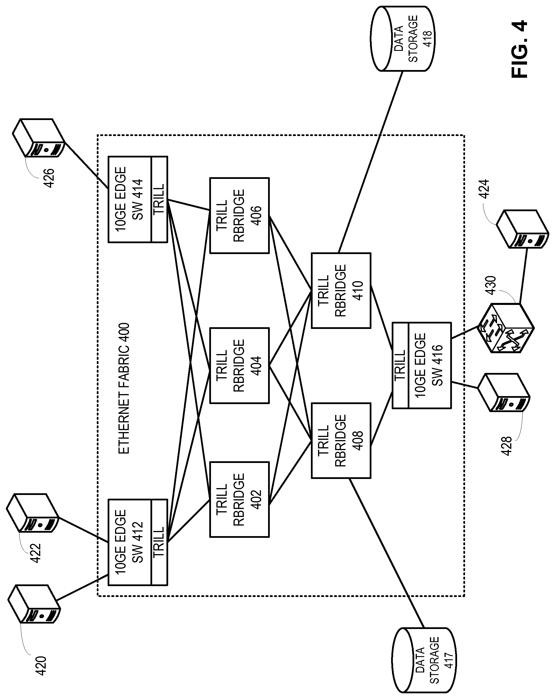
FIG. 4 illustrates an exemplary configuration of how an Ethernet fabric switch can be connected to different edge networks, in accordance with an embodiment of the present invention.
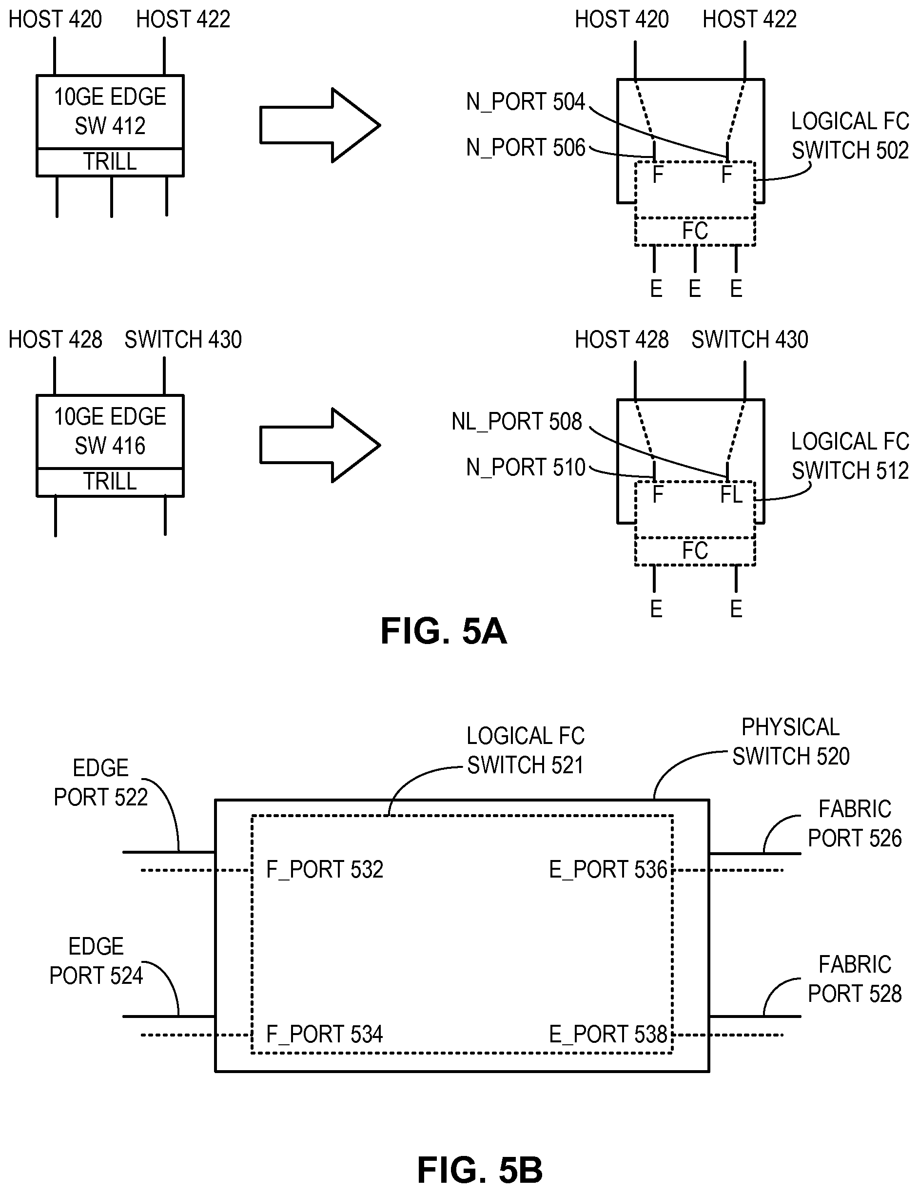
FIG. 5A illustrates how a logical Fibre Channel switch fabric is formed in an Ethernet fabric switch in conjunction with the example in FIG. 4, in accordance with an embodiment of the present invention.
FIG. 5B illustrates an example of how a logical FC switch can be created within a physical Ethernet switch, in accordance with one embodiment of the present invention.
FIG. 6 illustrates an exemplary Ethernet fabric configuration database, in accordance with an embodiment of the present invention.
FIG. 7 illustrates an exemplary process of a switch joining an Ethernet fabric, in accordance with an embodiment of the present invention.
FIG. 8 presents a flowchart illustrating the process of looking up an ingress frame's destination MAC address and forwarding the frame in an Ethernet fabric switch, in accordance with one embodiment of the present invention.
FIG. 9 illustrates how data frames and control frames are transported through an Ethernet fabric, in accordance with one embodiment of the present invention.
FIG. 10 illustrates an exemplary switch that facilitates formation of an Ethernet fabric, in accordance with an embodiment of the present invention.
DETAILED DESCRIPTION
The following description is presented to enable any person skilled in the art to make and use the invention, and is provided in the context of a particular application and its requirements. Various modifications to the disclosed embodiments will be readily apparent to those skilled in the art, and the general principles defined herein may be applied to other embodiments and applications without departing from the spirit and scope of the present invention. Thus, the present invention is not limited to the embodiments shown, but is to be accorded the widest scope consistent with the claims.
Overview
In embodiments of the present invention, the problem of building a versatile, cost-effective, and scalable switching system is solved by running a control plane with automatic configuration capabilities (such as the Fibre Channel control plane) over a conventional transport protocol, thereby allowing a number of switches to be inter-connected to form a single, scalable logical switch without requiring burdensome manual configuration. As a result, one can form a large-scale logical switch (referred to as a "switch fabric" or "Ethernet fabric" herein) using a number of smaller physical switches. The automatic configuration capability provided by the control plane running on each physical switch allows any number of switches to be connected in an arbitrary topology without requiring tedious manual configuration of the ports and links. This feature makes it possible to use many smaller, inexpensive switches to construct a large switch fabric or cluster, which can be viewed as a single logical switch externally.
It should be noted that an Ethernet fabric is not the same as conventional switch stacking. In switch stacking, multiple switches are interconnected at a common location (often within the same rack), based on a particular topology, and manually configured in a particular way. These stacked switches typically share a common address, e.g., IP address, so they can be addressed as a single switch externally. Furthermore, switch stacking requires a significant amount of manual configuration of the ports and inter-switch links. The need for manual configuration prohibits switch stacking from being a viable option in building a large-scale switching system. The topology restriction imposed by switch stacking also limits the number of switches that can be stacked. This is because it is very difficult, if not impossible, to design a stack topology that allows the overall switch bandwidth to scale adequately with the number of switch units.
In contrast, an Ethernet fabric can include an arbitrary number of switches with individual addresses, can be based on an arbitrary topology, and does not require extensive manual configuration. The switches can reside in the same location, or be distributed over different locations. These features overcome the inherent limitations of switch stacking and make it possible to build a large "switch farm" which can be treated as a single, logical switch. Due to the automatic configuration capabilities of the Ethernet fabric, an individual physical switch can dynamically join or leave the fabric without disrupting services to the rest of the network.
Furthermore, the automatic and dynamic configurability of Ethernet fabric allows a network operator to build its switching system in a distributed and "pay-as-you-grow" fashion without sacrificing scalability. The Ethernet fabric's ability to respond to changing network conditions makes it an ideal solution in a virtual computing environment, where network loads often change with time.
Although this disclosure is presented using examples based on the Transparent Interconnection of Lots of Links (TRILL) as the transport protocol and the Fibre Channel (FC) fabric protocol as the control-plane protocol, embodiments of the present invention are not limited to TRILL networks, or networks defined in a particular Open System Interconnection Reference Model (OSI reference model) layer. For example, an Ethernet fabric can also be implemented with switches running multi-protocol label switching (MPLS) protocols for the transport. In addition, the terms "RBridge" and "switch" are used interchangeably in this disclosure. The use of the term "RBridge" does not limit embodiments of the present invention to TRILL networks only. The TRILL protocol is described in IETF draft "RBridges: Base Protocol Specification," available at http://tools.ietf.org/html/draft-ietf-trill-rbridge-protocol, which is incorporated by reference herein
The terms "switch fabric," "Ethernet fabric," "Ethernet fabric switch," "switch cluster," "virtual cluster switch," "virtual cluster switching," and "VCS" refer to a group of interconnected physical switches operating as a single logical switch. The control plane for these physical switches provides the ability to automatically configure a given physical switch, so that when it joins the Ethernet fabric, little or no manual configuration is required. "Ethernet fabric" or "VCS" is not limited to a specific product family from a particular vendor. In addition, "Ethernet fabric" or "VCS" is not the only term that can be used to name the switching system described herein. Other terms, such as "Ethernet fabric switch," "fabric switch," "cluster switch," "Ethernet mesh switch," and "mesh switch" can also be used to describe the same switching system. Hence, in some embodiments, these terms and "Ethernet fabric" can be used interchangeably.
The term "RBridge" refers to routing bridges, which are bridges implementing the TRILL protocol as described in IETF draft "RBridges: Base Protocol Specification." Embodiments of the present invention are not limited to the application among RBridges. Other types of switches, routers, and forwarders can also be used.
The terms "frame" or "packet" refer to a group of bits that can be transported together across a network. "Frame" should not be interpreted as limiting embodiments of the present invention to layer-2 networks. "Packet" should not be interpreted as limiting embodiments of the present invention to layer-3 networks. "Frame" or "packet" can be replaced by other terminologies referring to a group of bits, such as "cell" or "datagram."
Ethernet Fabric Architecture
FIG. 1A illustrates an exemplary Ethernet fabric system, in accordance with an embodiment of the present invention. In this example, an Ethernet fabric 100 includes physical switches 101, 102, 103, 104, 105, 106, and 107. A given physical switch runs an Ethernet-based transport protocol on its ports (e.g., TRILL on its inter-switch ports, and Ethernet transport on its external ports), while its control plane runs an FC switch fabric protocol stack. The TRILL protocol facilitates transport of Ethernet frames within and across Ethernet fabric 100 in a routed fashion (since TRILL provides routing functions to Ethernet frames). The FC switch fabric protocol stack facilitates the automatic configuration of individual physical switches, in a way similar to how a conventional FC switch fabric is formed and automatically configured. In one embodiment, Ethernet fabric 100 can appear externally as an ultra-high-capacity Ethernet switch. More details on FC network architecture, protocols, naming/address conventions, and various standards are available in the documentation available from the NCITS/ANSI T11 committee (www.t11.org) and publicly available literature, such as "Designing Storage Area Networks," by Tom Clark, 2nd Ed., Addison Wesley, 2003, the disclosures of which are incorporated by reference in their entirety herein.
A physical switch may dedicate a number of ports for external use (i.e., to be coupled to end hosts or other switches external to the Ethernet fabric) and other ports for inter-switch connection. Viewed externally, Ethernet fabric 100 appears to be one switch to a device from the outside, and any port from any of the physical switches is considered one port on the Ethernet fabric. For example, port groups 110 and 112 are both Ethernet fabric external ports and can be treated equally as if they were ports on a common physical switch, although switches 105 and 107 may reside in two different locations.
The physical switches can reside at a common location, such as a data center or central office, or be distributed in different locations. Hence, it is possible to construct a large-scale centralized switching system using many smaller, inexpensive switches housed in one or more chassis at the same location. It is also possible to have the physical switches placed at different locations, thus creating a logical switch that can be accessed from multiple locations. The topology used to interconnect the physical switches can also be versatile. Ethernet fabric 100 is based on a mesh topology. In further embodiments, an Ethernet fabric switch can be based on a ring, tree, or other types of topologies.
In one embodiment, the protocol architecture of an Ethernet fabric switch is based on elements from the standard IEEE 802.1Q Ethernet bridge, which is emulated over a transport based on the Fibre Channel Framing and Signaling-2 (FC-FS-2) standard. The resulting switch is capable of transparently switching frames from an ingress Ethernet port from one of the edge switches to an egress Ethernet port on a different edge switch through the Ethernet fabric.
Because of its automatic configuration capability, an Ethernet fabric switch can be dynamically expanded as the network demand increases. In addition, one can build a large-scale switch using many smaller physical switches without the burden of manual configuration. For example, it is possible to build a high-throughput fully non-blocking switch using a number of smaller switches. This ability to use small switches to build a large non-blocking switch significantly reduces the cost associated switch complexity. FIG. 1B presents an exemplary Ethernet fabric with its member switches connected in a CLOS network, in accordance with one embodiment of the present invention. In this example, an Ethernet fabric 120 forms a fully non-blocking 8.times.8 switch, using eight 4.times.4 switches and four 2.times.2 switches connected in a three-stage CLOS network. A large-scale switch with a higher port count can be built in a similar way.
FIG. 2 illustrates the protocol stack within an Ethernet fabric switch, in accordance with an embodiment of the present invention. In this example, two physical switches 202 and 204 are illustrated within an Ethernet fabric 200. Switch 202 includes an ingress Ethernet port 206 and an inter-switch port 208. Switch 204 includes an egress Ethernet port 212 and an inter-switch port 210. Ingress Ethernet port 206 receives Ethernet frames from an external device. The Ethernet header is processed by a medium access control (MAC) layer protocol. On top of the MAC layer is a MAC client layer, which hands off the information extracted from the frame's Ethernet header to a forwarding database (FDB) 214. Typically, in a conventional IEEE 802.1Q Ethernet switch, FDB 214 is maintained locally in a switch, which would perform a lookup based on the destination MAC address and the VLAN indicated in the Ethernet frame. The lookup result would provide the corresponding output port. However, since Ethernet fabric 200 is not one single physical switch, FDB 214 would return the egress switch's identifier (i.e., switch 204's identifier). In one embodiment, FDB 214 is a data structure replicated and distributed among all the physical switches. That is, every physical switch maintains its own copy of FDB 214. When a given physical switch learns the source MAC address and VLAN of an Ethernet frame (similar to what a conventional IEEE 802.1Q Ethernet switch does) as being reachable via the ingress port, the learned MAC and VLAN information, together with the ingress Ethernet port and switch information, is propagated to all the physical switches so every physical switch's copy of FDB 214 can remain synchronized. This prevents forwarding based on stale or incorrect information when there are changes to the connectivity of end stations or edge networks to the Ethernet fabric.
The forwarding of the Ethernet frame between ingress switch 202 and egress switch 204 is performed via inter-switch ports 208 and 210. The frame transported between the two inter-switch ports is encapsulated in an outer MAC header and a TRILL header, in accordance with the TRILL standard. The protocol stack associated with a given inter-switch port includes the following (from bottom up): MAC layer, TRILL layer, FC-FS-2 layer, FC E-Port layer, and FC link services (FC-LS) layer. The FC-LS layer is responsible for maintaining the connectivity information of a physical switch's neighbor, and populating an FC routing information base (RIB) 222. This operation is similar to what is done in an FC switch fabric. The FC-LS protocol is also responsible for handling joining and departure of a physical switch in Ethernet fabric 200. The operation of the FC-LS layer is specified in the FC-LS standard, which is available at http://www.t11.org/ftp/t11/member/fc/ls/06-393v5.pdf, the disclosure of which is incorporated herein in its entirety.
During operation, when FDB 214 returns the egress switch 204 corresponding to the destination MAC address of the ingress Ethernet frame, the destination egress switch's identifier is passed to a path selector 218. Path selector 218 performs a fabric shortest-path first (FSPF)-based route lookup in conjunction with RIB 222, and identifies the next-hop switch within Ethernet fabric 200. In other words, the routing is performed by the FC portion of the protocol stack, similar to what is done in an FC switch fabric.
Also included in each physical switch are an address manager 216 and a fabric controller 220. Address manager 216 is responsible for configuring the address of a physical switch when the switch first joins the Ethernet fabric. For example, when switch 202 first joins Ethernet fabric 200, address manager 216 can negotiate a new FC switch domain ID, which is subsequently used to identify the switch within Ethernet fabric 200. Fabric controller 220 is responsible for managing and configuring the logical FC switch fabric formed on the control plane of Ethernet fabric 200.
One way to understand the protocol architecture of Ethernet fabric is to view the Ethernet fabric as an FC switch fabric with an Ethernet/TRILL transport. Each physical switch, from an external point of view, appears to be a TRILL RBridge. However, the switch's control plane implements the FC switch fabric software. In other words, embodiments of the present invention facilitate the construction of an "Ethernet switch fabric" running on FC control software. This unique combination provides the Ethernet fabric with automatic configuration capability and allows it to provide the ubiquitous Ethernet services in a very scalable fashion.
FIG. 3 illustrates an exemplary configuration of an Ethernet fabric switch, in accordance with an embodiment of the present invention. In this example, an Ethernet fabric 300 includes four physical switches 302, 304, 306, and 308. Ethernet fabric 300 constitutes an access layer which is coupled to two aggregation switches 310 and 312. Note that the physical switches within Ethernet fabric 300 are connected in a ring topology. Aggregation switch 310 or 312 can connect to any of the physical switches within Ethernet fabric 300. For example, aggregation switch 310 is coupled to physical switches 302 and 308. These two links are viewed as a trunked link to Ethernet fabric 300, since the corresponding ports on switches 302 and 308 are considered to be from the same logical switch, Ethernet fabric 300. Note that, without Ethernet fabric, such topology would not have been possible, because the FDB needs to remain synchronized, which is facilitated by the Ethernet fabric.
FIG. 4 illustrates an exemplary configuration of how an Ethernet fabric switch can be connected to different edge networks, in accordance with an embodiment of the present invention. In this example, an Ethernet fabric 400 includes a number of TRILL RBridges 402, 404, 406, 408, and 410, which are controlled by the FC switch-fabric control plane. Also included in Ethernet fabric 400 are RBridges 412, 414, and 416. Each RBridge has a number of edge ports which can be connected to external edge networks.
For example, RBridge 412 is coupled with hosts 420 and 422 via 10GE ports. RBridge 414 is coupled to a host 426 via a 10GE port. These RBridges have TRILL-based inter-switch ports for connection with other TRILL RBridges in Ethernet fabric 400. Similarly, RBridge 416 is coupled to host 428 and an external Ethernet switch 430, which is coupled to an external network that includes a host 424. In addition, network equipment can also be coupled directly to any of the physical switches in Ethernet fabric 400. As illustrated here, TRILL RBridge 408 is coupled to a data storage 417, and TRILL RBridge 410 is coupled to a data storage 418.
Although the physical switches within Ethernet fabric 400 are labeled as "TRILL RBridges," they are different from the conventional TRILL RBridge in the sense that they are controlled by the FC switch fabric control plane. In other words, the assignment of switch addresses, link discovery and maintenance, topology convergence, routing, and forwarding can be handled by the corresponding FC protocols. Particularly, each TRILL RBridge's switch ID or nickname is mapped from the corresponding FC switch domain ID, which can be automatically assigned when a switch joins Ethernet fabric 400 (which is logically similar to an FC switch fabric).
Note that TRILL is only used as a transport between the switches within Ethernet fabric 400. This is because TRILL can readily accommodate native Ethernet frames. Also, the TRILL standards provide a ready-to-use forwarding mechanism that can be used in any routed network with arbitrary topology (although the actual routing in the Ethernet fabric is done by the FC switch fabric protocols). Embodiments of the present invention should be not limited to using only TRILL as the transport. Other protocols (such as multi-protocol label switching (MPLS) or Internet Protocol (IP)), either public or proprietary, can also be used for the transport.
Ethernet Fabric Formation
In one embodiment, an Ethernet fabric is created by instantiating a logical FC switch in the control plane of each switch. After the logical FC switch is created, a virtual generic port (denoted as G_Port) is created for each Ethernet port on the RBridge. A G_Port assumes the normal G_Port behavior from the FC switch perspective. However, in this case, since the physical links are based on Ethernet, the specific transition from a G_Port to either an FC_F Port or E_Port is determined by the underlying link and physical layer protocols. For example, if the physical Ethernet port is connected to an external device which lacks Ethernet fabric capabilities, the corresponding G_Port will be turned into an F_Port. On the other hand, if the physical Ethernet port is connected to a switch with Ethernet fabric capabilities and it is confirmed that the switch on the other side is part of an Ethernet fabric, then the G_Port will be turned into an E_port.
FIG. 5A illustrates how a logical Fibre Channel switch fabric is formed in an Ethernet fabric switch in conjunction with the example in FIG. 4, in accordance with an embodiment of the present invention. RBridge 412 contains a virtual, logical FC switch 502. Corresponding to the physical Ethernet ports coupled to hosts 420 and 422, logical FC switch 502 has two logical F_Ports, which are logically coupled to hosts 420 and 422. In addition, two logical N_Ports, 506 and 504, are created for hosts 420 and 422, respectively. On the fabric side, logical FC switch 502 has three logical E_Ports, which are to be coupled with other logical FC switches in the logical FC switch fabric in the Ethernet fabric.
Similarly, RBridge 416 contains a virtual, logical FC switch 512. Corresponding to the physical Ethernet ports coupled to host 428 and external switch 430, logical FC switch 512 has a logical F_Port coupled to host 428, and a logical FL_Port coupled to switch 430. In addition, a logical N_Port 510 is created for host 428, and a logical NL_Port 508 is created for switch 430. Note that the logical FL_Port is created because that port is coupled to a switch (switch 430), instead of a regular host, and therefore logical FC switch 512 assumes an arbitrated loop topology leading to switch 430. Logical NL_Port 508 is created based on the same reasoning to represent a corresponding NL_Port on switch 430. On the fabric side, logical FC switch 512 has two logical E_Ports, which to be coupled with other logical FC switches in the logical FC switch fabric in the Ethernet fabric.
FIG. 5B illustrates an example of how a logical FC switch can be created within a physical Ethernet switch, in accordance with one embodiment of the present invention. The term "fabric port" refers to a port used to couple multiple switches in an Ethernet fabric. The clustering protocols control the forwarding between fabric ports. The term "edge port" refers to a port that is not currently coupled to another switch unit in the Ethernet fabric. Standard IEEE 802.1Q and layer-3 protocols control forwarding on edge ports.
In the example illustrated in FIG. 5B, a logical FC switch 521 is created within a physical switch (RBridge) 520. Logical FC switch 521 participates in the FC switch fabric protocol via logical inter-switch links (ISLs) to other switch units and has an FC switch domain ID assigned to it just as a physical FC switch does. In other words, the domain allocation, principal switch selection, and conflict resolution work just as they would on a physical FC ISL.
The physical edge ports 522 and 524 are mapped to logical F_Ports 532 and 534, respectively. In addition, physical fabric ports 526 and 528 are mapped to logical E_Ports 536 and 538, respectively. Initially, when logical FC switch 521 is created (for example, during the boot-up sequence), logical FC switch 521 only has four G_Ports which correspond to the four physical ports. These G_Ports are subsequently mapped to F_Ports or E_Ports, depending on the devices coupled to the physical ports.
Neighbor discovery is the first step in Ethernet fabric formation between two Ethernet fabric-capable switches. It is assumed that the verification of Ethernet fabric capability can be carried out by a handshake process between two neighbor switches when the link is first brought up.
In general, an Ethernet fabric presents itself as one unified switch composed of multiple member switches. Hence, the creation and configuration of Ethernet fabric is of critical importance. The Ethernet fabric configuration is based on a distributed database, which is replicated and distributed over all switches.
In one embodiment, an Ethernet fabric configuration database includes a global configuration table (GT) of the Ethernet fabric and a list of switch description tables (STs), each of which describes an Ethernet fabric member switch. In its simplest form, a member switch can have an Ethernet fabric configuration database that includes a global table and one switch description table, e.g., [<GT><ST>]. An Ethernet fabric with multiple switches will have a configuration database that has a single global table and multiple switch description tables, e.g., [<GT><ST0><ST1> . . . <STn-1>]. The number n corresponds to the number of member switches in the Ethernet fabric. In one embodiment, the GT can include at least the following information: the Ethernet fabric ID, number of nodes in the Ethernet fabric, a list of VLANs supported by the Ethernet fabric, a list of all the switches (e.g., list of FC switch domain IDs for all active switches) in the Ethernet fabric, and the FC switch domain ID of the principal switch (as in a logical FC switch fabric). A switch description table can include at least the following information: the IN_VCS flag, indication whether the switch is a principal switch in the logical FC switch fabric, the FC switch domain ID for the switch, the FC world-wide name (WWN) for the corresponding logical FC switch; the mapped ID of the switch, and optionally the IP address of the switch.
In addition, each switch's global configuration database is associated with a transaction ID. The transaction ID specifies the latest transaction (e.g., update or change) incurred to the global configuration database. The transaction IDs of the global configuration databases in two switches can be compared to determine which database has the most current information (i.e., the database with the more current transaction ID is more up-to-date). In one embodiment, the transaction ID is the switch's serial number plus a sequential transaction number. This configuration can unambiguously resolve which switch has the latest configuration.
As illustrated in FIG. 6, an Ethernet fabric member switch typically maintains two configuration tables that describe its instance: an Ethernet fabric configuration database 600, and a default switch configuration table 604. Ethernet fabric configuration database 600 describes the Ethernet fabric configuration when the switch is part of an Ethernet fabric. Default switch configuration table 604 describes the switch's default configuration. Ethernet fabric configuration database 600 includes a GT 602, which includes an Ethernet fabric identifier (denoted as VCS_ID) and a VLAN list within the Ethernet fabric. Also included in Ethernet fabric configuration database 600 are a number of STs, such as ST0, ST1, and STn. Each ST includes the corresponding member switch's MAC address and FC switch domain ID, as well as the switch's interface details. Note that each switch also has an Ethernet fabric-mapped ID which is a switch index within the Ethernet fabric.
In one embodiment, each switch also has an Ethernet fabric-mapped ID (denoted as "mappedID"), which is a switch index within the Ethernet fabric. This mapped ID is unique and persistent within the Ethernet fabric. That is, when a switch joins the Ethernet fabric for the first time, the Ethernet fabric assigns a mapped ID to the switch. This mapped ID persists with the switch, even if the switch leaves the Ethernet fabric. When the switch joins the Ethernet fabric again at a later time, the same mapped ID is used by the Ethernet fabric to retrieve previous configuration information for the switch. This feature can reduce the amount of configuration overhead in an Ethernet fabric. Also, the persistent mapped ID allows the Ethernet fabric to "recognize" a previously configured member switch when it re-joins the Ethernet fabric, since a dynamically assigned FC fabric domain ID would change each time the member switch joins and is configured by the Ethernet fabric.
Default switch configuration table 604 has an entry for the mappedID that points to the corresponding ST in Ethernet fabric configuration database 600. Note that only Ethernet fabric configuration database 600 is replicated and distributed to all switches in the Ethernet fabric. Default switch configuration table 604 is local to a particular member switch.
The "IN_VCS" value in default switch configuration table 604 indicates whether the member switch is part of an Ethernet fabric. A switch is considered to be "in an Ethernet fabric" when it is assigned one of the FC switch domains by the FC switch fabric with two or more switch domains. If a switch is part of an FC switch fabric that has only one switch domain, i.e., its own switch domain, then the switch is considered to be "not in an Ethernet fabric."
When a switch is first connected to an Ethernet fabric, the logical FC switch fabric formation process allocates a new switch domain ID to the joining switch. In one embodiment, only the switches directly connected to the new switch participate in the Ethernet fabric join operation.
Note that in the case where the global configuration database of a joining switch is current and in sync with the global configuration database of the Ethernet fabric based on a comparison of the transaction IDs of the two databases (e.g., when a member switch is temporarily disconnected from the Ethernet fabric and re-connected shortly afterward), a trivial merge is performed. That is, the joining switch can be connected to the Ethernet fabric, and no change or update to the global Ethernet fabric configuration database is required.
FIG. 7 illustrates an exemplary process of a switch joining an Ethernet fabric, in accordance with an embodiment of the present invention. In this example, it is assumed that a switch 702 is within an existing Ethernet fabric, and a switch 704 is joining the Ethernet fabric. During operation, both switches 702 and 704 trigger an FC State Change Notification (SCN) process. Subsequently, both switches 702 and 704 perform a PRE-INVITE operation. The pre-invite operation involves the following process.
When a switch joins the Ethernet fabric via a link, both neighbors on each end of the link present to the other switch an Ethernet fabric four-tuple of <Prior VCS_ID, SWITCH_MAC, mappedID, IN_VCS> from a prior incarnation, if any. Otherwise, the switch presents to the counterpart a default tuple. If the VCS_ID value was not set from a prior join operation, a VCS_ID value of -1 is used. In addition, if a switch's IN_VCS flag is set to 0, it sends out its interface configuration to the neighboring switch. In the example in FIG. 7, both switches 702 and 704 send the above information to the other switch.
After the above PRE-INVITE operation, a driver switch for the join process is selected. By default, if a switch's IN_VCS value is 1 and the other switch's IN_VCS value is 0, the switch with IN_VCS=1 is selected as the driver switch. If both switches have their IN_VCS values as 1, then nothing happens, i.e., the PRE-INVITE operation would not lead to an INVITE operation. If both switches have their IN_VCS values as 0, then one of the switches is elected to be the driving switch (for example, the switch with a lower FC switch domain ID value). The driving switch's IN_VCS value is then set to 1 and drives the join process.
After switch 702 is selected as the driver switch, switch 702 then attempts to reserve a slot in the Ethernet fabric configuration database corresponding to the mappedID value in switch 704's PRE-INVITE information. Next, switch 702 searches the Ethernet fabric configuration database for switch 704's MAC address in any mappedID slot. If such a slot is found, switch 702 copies all information from the identified slot into the reserved slot. Otherwise, switch 702 copies the information received during the PRE-INVITE from switch 704 into the Ethernet fabric configuration database. The updated Ethernet fabric configuration database is then propagated to all the switches in the Ethernet fabric as a prepare operation in the database (note that the update is not committed to the database yet).
Subsequently, the prepare operation may or may not result in configuration conflicts, which may be flagged as warnings or fatal errors. Such conflicts can include inconsistencies between the joining switch's local configuration or policy setting and the Ethernet fabric configuration. For example, a conflict arises when the joining switch is manually configured to allow packets with a particular VLAN value to pass through, whereas the Ethernet fabric does not allow this VLAN value to enter the switch fabric from this particular RBridge (for example, when this VLAN value is reserved for other purposes). In one embodiment, the prepare operation is handled locally and/or remotely in concert with other Ethernet fabric member switches. If there is an un-resolvable conflict, switch 702 sends out a PRE-INVITE-FAILED message to switch 704. Otherwise, switch 702 generates an INVITE message with the Ethernet fabric's merged view of the switch (i.e., the updated Ethernet fabric configuration database).
Upon receiving the INVITE message, switch 704 either accepts or rejects the INVITE. The INVITE can be rejected if the configuration in the INVITE is in conflict with what switch 704 can accept. If the INVITE is acceptable, switch 704 sends back an INVITE-ACCEPT message in response. The INVITE-ACCEPT message then triggers a final database commit throughout all member switches in the Ethernet fabric. In other words, the updated Ethernet fabric configuration database is updated, replicated, and distributed to all the switches in the Ethernet fabric.
Layer-2 Services in Ethernet Fabric
In one embodiment, each Ethernet fabric switch unit performs source MAC address learning, similar to what an Ethernet bridge does. Each {MAC address, VLAN} tuple learned on a physical port on an Ethernet fabric switch unit is registered into the local Fibre Channel Name Server (FC-NS) via a logical Nx_Port interface corresponding to that physical port. This registration binds the address learned to the specific interface identified by the Nx_Port. Each FC-NS instance on each Ethernet fabric switch unit coordinates and distributes all locally learned {MAC address, VLAN} tuples with every other FC-NS instance in the fabric. This feature allows the dissemination of locally learned {MAC addresses, VLAN} information to every switch in the Ethernet fabric. In one embodiment, the learned MAC addresses are aged locally by individual switches.
FIG. 8 presents a flowchart illustrating the process of looking up an ingress frame's destination MAC address and forwarding the frame in an Ethernet fabric, in accordance with one embodiment of the present invention. During operation, an Ethernet fabric switch receives an Ethernet frame at one of its Ethernet ports (operation 802). The switch then extracts the frame's destination MAC address and queries the local FC Name Server (operation 804). Next, the switch determines whether the FC-NS returns an N_Port or an NL_Port identifier that corresponds to an egress Ethernet port (operation 806).
If the FC-NS returns a valid result, the switch forwards the frame to the identified N_Port or NL_Port (operation 808). Otherwise, the switch floods the frame on the TRILL multicast tree as well as on all the N_Ports and NL_Ports that participate in that VLAN (operation 810). This flood/broadcast operation is similar to the broadcast process in a conventional TRILL RBridge, wherein all the physical switches in the Ethernet fabric will receive and process this frame, and learn the source address corresponding to the ingress RBridge. In addition, each receiving switch floods the frame to its local ports that participate in the frame's VLAN (operation 812). Note that the above operations are based on the presumption that there is a one-to-one mapping between a switch's TRILL identifier (or nickname) and its FC switch domain ID. There is also a one-to-one mapping between a physical Ethernet port on a switch and the corresponding logical FC port.
End-To-End Frame Delivery and Exemplary Ethernet Fabric Member Switch
FIG. 9 illustrates how data frames and control frames are transported in an Ethernet fabric, in accordance with an embodiment of the present invention. In this example, an Ethernet fabric 930 includes member switches 934, 936, 938, 944, 946, and 948. An end host 932 is communicating with an end host 940. Switch 934 is the ingress Ethernet fabric member switch corresponding to host 932, and switch 938 is the egress Ethernet fabric member switch corresponding to host 938. During operation, host 932 sends an Ethernet frame 933 to host 940. Ethernet frame 933 is first encountered by ingress switch 934. Upon receiving frame 933, switch 934 first extracts frame 933's destination MAC address. Switch 934 then performs a MAC address lookup using the Ethernet name service, which provides the egress switch identifier (i.e., the RBridge identifier of egress switch 938). Based on the egress switch identifier, the logical FC switch in switch 934 performs a routing table lookup to determine the next-hop switch, which is switch 936, and the corresponding output port for forwarding frame 933. The egress switch identifier is then used to generate a TRILL header (which specifies the destination switch's RBridge identifier), and the next-hop switch information is used to generate an outer Ethernet header. Subsequently, switch 934 encapsulates frame 933 with the proper TRILL header and outer Ethernet header, and sends the encapsulated frame 935 to switch 936. Based on the destination RBridge identifier in the TRILL header of frame 935, switch 936 performs a routing table lookup and determines the next hop. Based on the next-hop information, switch 936 updates frame 935's outer Ethernet header and forwards frame 935 to egress switch 938.
Upon receiving frame 935, switch 938 determines that it is the destination RBridge based on frame 935's TRILL header. Correspondingly, switch 938 strips frame 935 of its outer Ethernet header and TRILL header, and inspects the destination MAC address of its inner Ethernet header. Switch 938 then performs a MAC address lookup and determines the correct output port leading to host 940. Subsequently, the original Ethernet frame 933 is transmitted to host 940.
As described above, the logical FC switches within the physical Ethernet fabric member switches may send control frames to one another (for example, to update the Ethernet fabric global configuration database or to notify other switches of the learned MAC addresses). In one embodiment, such control frames can be FC control frames encapsulated in a TRILL header and an outer Ethernet header. For example, if the logical FC switch in switch 944 is in communication with the logical FC switch in switch 938, switch 944 can sends a TRILL-encapsulated FC control frame 942 to switch 946. Switch 946 can forward frame 942 just like a regular data frame, since switch 946 is not concerned with the payload in frame 942.
FIG. 10 illustrates an exemplary Ethernet fabric member switch, in accordance with one embodiment of the present invention. In this example, the Ethernet fabric member switch is a TRILL RBridge 1000 running special Ethernet fabric software. RBridge 1000 includes a number of Ethernet communication ports 1001, which can transmit and receive Ethernet frames and/or TRILL encapsulated frames. Also included in RBridge 1000 is a packet processor 1002, a virtual FC switch management module 1004, a logical FC switch 1005, an Ethernet fabric configuration database 1006, and a TRILL header generation module 1008.
During operation, packet processor 1002 extracts the source and destination MAC addresses of incoming frames, and attaches proper Ethernet or TRILL headers to outgoing frames. Virtual FC switch management module 1004 maintains the state of logical FC switch 1005, which is used to join other Ethernet fabric switches using the FC switch fabric protocols. Ethernet fabric configuration database 1006 maintains the configuration state of every switch within the Ethernet fabric. TRILL header generation module 1008 is responsible for generating property TRILL headers for frames that are to be transmitted to other Ethernet fabric member switches.
The methods and processes described herein can be embodied as code and/or data, which can be stored in a computer-readable non-transitory storage medium. When a computer system reads and executes the code and/or data stored on the computer-readable non-transitory storage medium, the computer system performs the methods and processes embodied as data structures and code and stored within the medium.
The methods and processes described herein can be executed by and/or included in hardware modules or apparatus. These modules or apparatus may include, but are not limited to, an application-specific integrated circuit (ASIC) chip, a field-programmable gate array (FPGA), a dedicated or shared processor that executes a particular software module or a piece of code at a particular time, and/or other programmable-logic devices now known or later developed. When the hardware modules or apparatus are activated, they perform the methods and processes included within them.
The foregoing descriptions of embodiments of the present invention have been presented only for purposes of illustration and description. They are not intended to be exhaustive or to limit this disclosure. Accordingly, many modifications and variations will be apparent to practitioners skilled in the art. The scope of the present invention is defined by the appended claims.
* * * * *
References
D00000
D00001
D00002
D00003
D00004
D00005
D00006
D00007
D00008
D00009
D00010
D00011
XML
uspto.report is an independent third-party trademark research tool that is not affiliated, endorsed, or sponsored by the United States Patent and Trademark Office (USPTO) or any other governmental organization. The information provided by uspto.report is based on publicly available data at the time of writing and is intended for informational purposes only.
While we strive to provide accurate and up-to-date information, we do not guarantee the accuracy, completeness, reliability, or suitability of the information displayed on this site. The use of this site is at your own risk. Any reliance you place on such information is therefore strictly at your own risk.
All official trademark data, including owner information, should be verified by visiting the official USPTO website at www.uspto.gov. This site is not intended to replace professional legal advice and should not be used as a substitute for consulting with a legal professional who is knowledgeable about trademark law.