Service chains for inter-cloud traffic
Sundararajan , et al.
U.S. patent number 10,666,612 [Application Number 16/001,039] was granted by the patent office on 2020-05-26 for service chains for inter-cloud traffic. This patent grant is currently assigned to CISCO TECHNOLOGY, INC.. The grantee listed for this patent is Cisco Technology, Inc.. Invention is credited to Samar Sharma, Balaji Sundararajan.


| United States Patent | 10,666,612 |
| Sundararajan , et al. | May 26, 2020 |
Service chains for inter-cloud traffic
Abstract
Systems, methods, and computer-readable media for creating service chains for inter-cloud traffic. In some examples, a system receives domain name system (DNS) queries associated with cloud domains and collects DNS information associated the cloud domains. The system spoofs DNS entries defining a subset of IPs for each cloud domain. Based on the spoofed DNS entries, the system creates IP-to-domain mappings associating each cloud domain with a respective IP from the subset of IPs. Based on the IP-to-domain mappings, the system programs different service chains for traffic between a private network and respective cloud domains. The system routes, through the respective service chain, traffic having a source associated with the private network and a destination matching the IP in the respective IP-to-domain mapping.
| Inventors: | Sundararajan; Balaji (Fremont, CA), Sharma; Samar (San Jose, CA) | ||||||||||
|---|---|---|---|---|---|---|---|---|---|---|---|
| Applicant: |
|
||||||||||
| Assignee: | CISCO TECHNOLOGY, INC. (San
Jose, CA) |
||||||||||
| Family ID: | 66913090 | ||||||||||
| Appl. No.: | 16/001,039 | ||||||||||
| Filed: | June 6, 2018 |
Prior Publication Data
| Document Identifier | Publication Date | |
|---|---|---|
| US 20190379635 A1 | Dec 12, 2019 | |
| Current U.S. Class: | 1/1 |
| Current CPC Class: | H04L 61/256 (20130101); H04L 45/38 (20130101); H04L 45/74 (20130101); H04L 63/101 (20130101); H04L 61/1511 (20130101); H04L 45/306 (20130101); H04L 45/22 (20130101); H04L 45/04 (20130101); H04L 41/0893 (20130101); H04L 45/64 (20130101) |
| Current International Class: | H04W 56/00 (20090101); H04L 12/721 (20130101); H04L 12/741 (20130101); H04L 29/06 (20060101); H04L 12/725 (20130101); H04L 12/707 (20130101); H04L 29/12 (20060101); H04L 12/715 (20130101); H04L 12/24 (20060101) |
| Field of Search: | ;370/392 |
References Cited [Referenced By]
U.S. Patent Documents
| 3629512 | December 1971 | Yuan |
| 4769811 | September 1988 | Eckberg, Jr. et al. |
| 5408231 | April 1995 | Bowdon |
| 5491690 | February 1996 | Alfonsi et al. |
| 5557609 | September 1996 | Shobatake et al. |
| 5600638 | February 1997 | Bertin et al. |
| 5687167 | November 1997 | Bertin et al. |
| 6115384 | September 2000 | Parzych |
| 6167438 | December 2000 | Yates et al. |
| 6400681 | June 2002 | Bertin et al. |
| 6661797 | December 2003 | Goel et al. |
| 6687229 | February 2004 | Kataria et al. |
| 6799270 | September 2004 | Bull et al. |
| 6888828 | May 2005 | Partanen et al. |
| 6993593 | January 2006 | Iwata |
| 7027408 | April 2006 | Nabkel et al. |
| 7062567 | June 2006 | Benitez et al. |
| 7095715 | August 2006 | Buckman et al. |
| 7096212 | August 2006 | Tribble et al. |
| 7139239 | November 2006 | Mcfarland et al. |
| 7165107 | January 2007 | Pouyoul et al. |
| 7197008 | March 2007 | Shabtay et al. |
| 7197660 | March 2007 | Liu et al. |
| 7209435 | April 2007 | Kuo et al. |
| 7227872 | June 2007 | Biswas et al. |
| 7231462 | June 2007 | Berthaud et al. |
| 7333990 | February 2008 | Thiagarajan et al. |
| 7443796 | October 2008 | Albert et al. |
| 7458084 | November 2008 | Zhang et al. |
| 7472411 | December 2008 | Wing et al. |
| 7486622 | February 2009 | Regan et al. |
| 7536396 | May 2009 | Johnson et al. |
| 7552201 | June 2009 | Areddu et al. |
| 7558261 | July 2009 | Arregoces et al. |
| 7567504 | July 2009 | Darling et al. |
| 7571470 | August 2009 | Arregoces et al. |
| 7573879 | August 2009 | Narad et al. |
| 7610375 | October 2009 | Portolani et al. |
| 7643468 | January 2010 | Arregoces et al. |
| 7644182 | January 2010 | Banerjee et al. |
| 7647422 | January 2010 | Singh et al. |
| 7657898 | February 2010 | Sadiq |
| 7657940 | February 2010 | Portolani et al. |
| 7668116 | February 2010 | Wijnands et al. |
| 7684321 | March 2010 | Muirhead et al. |
| 7738469 | June 2010 | Shekokar et al. |
| 7751409 | July 2010 | Carolan |
| 7793157 | September 2010 | Bailey et al. |
| 7814284 | October 2010 | Glass et al. |
| 7831693 | November 2010 | Lai |
| 7852785 | December 2010 | Lund et al. |
| 7860095 | December 2010 | Forissier et al. |
| 7860100 | December 2010 | Khalid et al. |
| 7895425 | February 2011 | Khalid et al. |
| 7899012 | March 2011 | Ho et al. |
| 7899861 | March 2011 | Feblowitz et al. |
| 7907595 | March 2011 | Khanna et al. |
| 7908480 | March 2011 | Firestone et al. |
| 7983174 | July 2011 | Monaghan et al. |
| 7990847 | August 2011 | Leroy et al. |
| 8000329 | August 2011 | Fendick et al. |
| 8018938 | September 2011 | Fromm et al. |
| 8094575 | January 2012 | Vadlakonda et al. |
| 8095683 | January 2012 | Balasubramaniam Chandra |
| 8116307 | February 2012 | Thesayi et al. |
| 8166465 | April 2012 | Feblowitz et al. |
| 8180909 | May 2012 | Hartman et al. |
| 8191119 | May 2012 | Wing et al. |
| 8195774 | June 2012 | Lambeth et al. |
| 8280354 | October 2012 | Smith et al. |
| 8281302 | October 2012 | Durazzo et al. |
| 8291108 | October 2012 | Raja et al. |
| 8305900 | November 2012 | Bianconi |
| 8311045 | November 2012 | Quinn et al. |
| 8316457 | November 2012 | Paczkowski et al. |
| 8355332 | January 2013 | Beaudette et al. |
| 8442043 | May 2013 | Sharma et al. |
| 8451817 | May 2013 | Cheriton |
| 8464336 | June 2013 | Wei et al. |
| 8479298 | July 2013 | Keith et al. |
| 8498414 | July 2013 | Rossi |
| 8520672 | August 2013 | Guichard et al. |
| 8601152 | December 2013 | Chou |
| 8605588 | December 2013 | Sankaran et al. |
| 8612612 | December 2013 | Dukes et al. |
| 8627328 | January 2014 | Mousseau et al. |
| 8645952 | February 2014 | Biswas et al. |
| 8676965 | March 2014 | Gueta |
| 8676980 | March 2014 | Kreeger et al. |
| 8700892 | April 2014 | Bollay et al. |
| 8724466 | May 2014 | Kenigsberg et al. |
| 8730980 | May 2014 | Bagepalli et al. |
| 8743885 | June 2014 | Khan et al. |
| 8751420 | June 2014 | Hjelm et al. |
| 8762534 | June 2014 | Hong et al. |
| 8762707 | June 2014 | Killian et al. |
| 8792490 | July 2014 | Jabr et al. |
| 8793400 | July 2014 | Mcdysan et al. |
| 8812730 | August 2014 | Vos et al. |
| 8819419 | August 2014 | Carlson et al. |
| 8825070 | September 2014 | Akhtar et al. |
| 8830834 | September 2014 | Sharma et al. |
| 8904037 | December 2014 | Haggar et al. |
| 8984284 | March 2015 | Purdy, Sr. et al. |
| 9001827 | April 2015 | Appenzeller |
| 9071533 | June 2015 | Hui et al. |
| 9077661 | July 2015 | Andreasen et al. |
| 9088584 | July 2015 | Feng et al. |
| 9130872 | September 2015 | Kumar et al. |
| 9143438 | September 2015 | Khan et al. |
| 9160797 | October 2015 | Mcdysan |
| 9178812 | November 2015 | Guichard et al. |
| 9189285 | November 2015 | Ng et al. |
| 9203711 | December 2015 | Agarwal et al. |
| 9253274 | February 2016 | Quinn et al. |
| 9300585 | March 2016 | Kumar et al. |
| 9311130 | April 2016 | Christenson et al. |
| 9319324 | April 2016 | Beheshti-Zavareh et al. |
| 9325565 | April 2016 | Yao et al. |
| 9325735 | April 2016 | Xie |
| 9338097 | May 2016 | Anand et al. |
| 9344337 | May 2016 | Kumar et al. |
| 9374297 | June 2016 | Bosch et al. |
| 9379931 | June 2016 | Bosch et al. |
| 9385950 | July 2016 | Quinn et al. |
| 9398486 | July 2016 | La Roche, Jr. et al. |
| 9407540 | August 2016 | Kumar et al. |
| 9413655 | August 2016 | Shatzkamer et al. |
| 9424065 | August 2016 | Singh et al. |
| 9436443 | September 2016 | Chiosi et al. |
| 9473570 | October 2016 | Bhanujan et al. |
| 9479443 | October 2016 | Bosch et al. |
| 9491094 | November 2016 | Patwardhan et al. |
| 9537836 | January 2017 | Maller et al. |
| 9558029 | January 2017 | Behera et al. |
| 9559970 | January 2017 | Kumar et al. |
| 9571405 | February 2017 | Pignataro et al. |
| 9608896 | March 2017 | Kumar et al. |
| 9660909 | May 2017 | Guichard et al. |
| 9723106 | August 2017 | Shen et al. |
| 9774533 | September 2017 | Zhang et al. |
| 9794379 | October 2017 | Kumar et al. |
| 9882776 | January 2018 | Aybay et al. |
| 2001/0023442 | September 2001 | Masters |
| 2002/0131362 | September 2002 | Callon |
| 2002/0156893 | October 2002 | Pouyoul et al. |
| 2002/0167935 | November 2002 | Nabkel et al. |
| 2003/0023879 | January 2003 | Wray |
| 2003/0026257 | February 2003 | Xu et al. |
| 2003/0037070 | February 2003 | Marston |
| 2003/0088698 | May 2003 | Singh et al. |
| 2003/0110081 | June 2003 | Tosaki et al. |
| 2003/0120816 | June 2003 | Berthaud et al. |
| 2003/0226142 | December 2003 | Rand |
| 2004/0109412 | June 2004 | Hansson et al. |
| 2004/0148391 | July 2004 | Lake, Sr. et al. |
| 2004/0199812 | October 2004 | Earl |
| 2004/0213160 | October 2004 | Regan et al. |
| 2004/0264481 | December 2004 | Darling et al. |
| 2004/0268357 | December 2004 | Joy et al. |
| 2005/0044197 | February 2005 | Lai |
| 2005/0058118 | March 2005 | Davis |
| 2005/0060572 | March 2005 | Kung |
| 2005/0086367 | April 2005 | Conta et al. |
| 2005/0120101 | June 2005 | Nocera |
| 2005/0152378 | July 2005 | Bango et al. |
| 2005/0157645 | July 2005 | Rabie et al. |
| 2005/0160180 | July 2005 | Rabje et al. |
| 2005/0204042 | September 2005 | Banerjee et al. |
| 2005/0210096 | September 2005 | Bishop et al. |
| 2005/0257002 | November 2005 | Nguyen |
| 2005/0281257 | December 2005 | Yazaki et al. |
| 2005/0286540 | December 2005 | Hurtta et al. |
| 2005/0289244 | December 2005 | Sahu et al. |
| 2006/0005240 | January 2006 | Sundarrajan et al. |
| 2006/0031374 | February 2006 | Lu et al. |
| 2006/0045024 | March 2006 | Previdi et al. |
| 2006/0074502 | April 2006 | Mcfarland |
| 2006/0092950 | May 2006 | Arregoces et al. |
| 2006/0095960 | May 2006 | Arregoces et al. |
| 2006/0112400 | May 2006 | Zhang et al. |
| 2006/0155862 | July 2006 | Kathi et al. |
| 2006/0168223 | July 2006 | Mishra et al. |
| 2006/0233106 | October 2006 | Achlioptas et al. |
| 2006/0233155 | October 2006 | Srivastava |
| 2007/0061441 | March 2007 | Landis et al. |
| 2007/0067435 | March 2007 | Landis et al. |
| 2007/0094397 | April 2007 | Krelbaum et al. |
| 2007/0143851 | June 2007 | Nicodemus et al. |
| 2007/0237147 | October 2007 | Quinn et al. |
| 2007/0250836 | October 2007 | Li et al. |
| 2008/0056153 | March 2008 | Liu |
| 2008/0080509 | April 2008 | Khanna et al. |
| 2008/0080517 | April 2008 | Roy et al. |
| 2008/0170542 | July 2008 | Hu |
| 2008/0177896 | July 2008 | Quinn et al. |
| 2008/0181118 | July 2008 | Sharma et al. |
| 2008/0196083 | August 2008 | Parks et al. |
| 2008/0209039 | August 2008 | Tracey et al. |
| 2008/0219287 | September 2008 | Krueger et al. |
| 2008/0225710 | September 2008 | Raja et al. |
| 2008/0291910 | November 2008 | Tadimeti et al. |
| 2009/0003364 | January 2009 | Fendick et al. |
| 2009/0006152 | January 2009 | Timmerman et al. |
| 2009/0037713 | February 2009 | Khalid et al. |
| 2009/0094684 | April 2009 | Chinnusamy et al. |
| 2009/0204612 | August 2009 | Keshavarz-nia et al. |
| 2009/0271656 | October 2009 | Yokota et al. |
| 2009/0300207 | December 2009 | Giaretta et al. |
| 2009/0305699 | December 2009 | Deshpande et al. |
| 2009/0328054 | December 2009 | Paramasivam et al. |
| 2010/0058329 | March 2010 | Durazzo et al. |
| 2010/0063988 | March 2010 | Khalid |
| 2010/0080226 | April 2010 | Khalid |
| 2010/0165985 | July 2010 | Sharma et al. |
| 2010/0191612 | July 2010 | Raleigh |
| 2011/0023090 | January 2011 | Asati et al. |
| 2011/0032833 | February 2011 | Zhang et al. |
| 2011/0055845 | March 2011 | Nandagopal et al. |
| 2011/0131338 | June 2011 | Hu |
| 2011/0137991 | June 2011 | Russell |
| 2011/0142056 | June 2011 | Manoj |
| 2011/0161494 | June 2011 | Mcdysan et al. |
| 2011/0222412 | September 2011 | Kompella |
| 2011/0255538 | October 2011 | Srinivasan et al. |
| 2011/0267947 | November 2011 | Dhar et al. |
| 2012/0131662 | May 2012 | Kuik et al. |
| 2012/0147894 | June 2012 | Mulligan et al. |
| 2012/0324442 | December 2012 | Barde |
| 2012/0331135 | December 2012 | Alon et al. |
| 2013/0003735 | January 2013 | Chao et al. |
| 2013/0003736 | January 2013 | Szyszko et al. |
| 2013/0036307 | February 2013 | Gagliano |
| 2013/0040640 | February 2013 | Chen et al. |
| 2013/0044636 | February 2013 | Koponen et al. |
| 2013/0103939 | April 2013 | Radpour |
| 2013/0121137 | May 2013 | Feng et al. |
| 2013/0124708 | May 2013 | Lee et al. |
| 2013/0148541 | June 2013 | Zhang |
| 2013/0163594 | June 2013 | Sharma et al. |
| 2013/0163606 | June 2013 | Bagepalli et al. |
| 2013/0238806 | September 2013 | Moen |
| 2013/0272305 | October 2013 | Lefebvre et al. |
| 2013/0311675 | November 2013 | Kancherla |
| 2013/0329584 | December 2013 | Ghose et al. |
| 2014/0010083 | January 2014 | Hamdi et al. |
| 2014/0010096 | January 2014 | Kamble et al. |
| 2014/0036730 | February 2014 | Nellikar et al. |
| 2014/0050223 | February 2014 | Foo et al. |
| 2014/0067758 | March 2014 | Boldyrev et al. |
| 2014/0105062 | April 2014 | McDysan et al. |
| 2014/0254603 | September 2014 | Banavalikar et al. |
| 2014/0259012 | September 2014 | Nandlall et al. |
| 2014/0279863 | September 2014 | Krishnamurthy et al. |
| 2014/0280836 | September 2014 | Kumar et al. |
| 2014/0317261 | October 2014 | Shatzkamer et al. |
| 2014/0321459 | October 2014 | Kumar et al. |
| 2014/0334295 | November 2014 | Guichard et al. |
| 2014/0344439 | November 2014 | Kempf et al. |
| 2014/0362682 | December 2014 | Guichard et al. |
| 2014/0362857 | December 2014 | Guichard et al. |
| 2014/0369209 | December 2014 | Khurshid et al. |
| 2014/0376558 | December 2014 | Rao et al. |
| 2015/0003455 | January 2015 | Haddad et al. |
| 2015/0012584 | January 2015 | Lo et al. |
| 2015/0012988 | January 2015 | Jeng et al. |
| 2015/0029871 | January 2015 | Frost et al. |
| 2015/0032871 | January 2015 | Allan et al. |
| 2015/0052516 | February 2015 | French et al. |
| 2015/0071285 | March 2015 | Kumar et al. |
| 2015/0074276 | March 2015 | DeCusatis et al. |
| 2015/0082308 | March 2015 | Kiess et al. |
| 2015/0085635 | March 2015 | Wijnands et al. |
| 2015/0085870 | March 2015 | Narasimha et al. |
| 2015/0089082 | March 2015 | Patwardhan et al. |
| 2015/0092564 | April 2015 | Aldrin |
| 2015/0103827 | April 2015 | Quinn et al. |
| 2015/0117308 | April 2015 | Kant |
| 2015/0124622 | May 2015 | Kovvali et al. |
| 2015/0131484 | May 2015 | Aldrin |
| 2015/0131660 | May 2015 | Shepherd et al. |
| 2015/0156035 | June 2015 | Foo et al. |
| 2015/0180725 | June 2015 | Varney et al. |
| 2015/0180767 | June 2015 | Tam et al. |
| 2015/0181309 | June 2015 | Shepherd et al. |
| 2015/0188949 | July 2015 | Mahaffey et al. |
| 2015/0195197 | July 2015 | Yong et al. |
| 2015/0222516 | August 2015 | Deval et al. |
| 2015/0222533 | August 2015 | Birrittella et al. |
| 2015/0236948 | August 2015 | Dunbar et al. |
| 2015/0319078 | November 2015 | Lee et al. |
| 2015/0319081 | November 2015 | Kasturi et al. |
| 2015/0326473 | November 2015 | Dunbar et al. |
| 2015/0333930 | November 2015 | Aysola et al. |
| 2015/0334027 | November 2015 | Bosch et al. |
| 2015/0341285 | November 2015 | Aysola et al. |
| 2015/0365324 | December 2015 | Kumar et al. |
| 2015/0365495 | December 2015 | Fan et al. |
| 2015/0381465 | December 2015 | Narayanan et al. |
| 2015/0381557 | December 2015 | Fan et al. |
| 2016/0028604 | January 2016 | Chakrabarti et al. |
| 2016/0028640 | January 2016 | Zhang et al. |
| 2016/0043952 | February 2016 | Zhang et al. |
| 2016/0050132 | February 2016 | Zhang |
| 2016/0080263 | March 2016 | Park et al. |
| 2016/0080496 | March 2016 | Falanga et al. |
| 2016/0099853 | April 2016 | Nedeltchev et al. |
| 2016/0119159 | April 2016 | Zhao et al. |
| 2016/0119253 | April 2016 | Kang et al. |
| 2016/0127139 | May 2016 | Tian et al. |
| 2016/0134518 | May 2016 | Callon et al. |
| 2016/0134535 | May 2016 | Callon |
| 2016/0139939 | May 2016 | Bosch et al. |
| 2016/0164776 | June 2016 | Biancaniello |
| 2016/0165014 | June 2016 | Nainar et al. |
| 2016/0173373 | June 2016 | Guichard et al. |
| 2016/0173464 | June 2016 | Wang et al. |
| 2016/0182336 | June 2016 | Doctor et al. |
| 2016/0182342 | June 2016 | Singaravelu et al. |
| 2016/0182684 | June 2016 | Connor et al. |
| 2016/0212017 | July 2016 | Li et al. |
| 2016/0226742 | August 2016 | Apathotharanan et al. |
| 2016/0248685 | August 2016 | Pignataro et al. |
| 2016/0285720 | September 2016 | Maenaa et al. |
| 2016/0323165 | November 2016 | Boucadair et al. |
| 2016/0352629 | December 2016 | Wang et al. |
| 2016/0380966 | December 2016 | Gunnalan et al. |
| 2017/0019303 | January 2017 | Swamy et al. |
| 2017/0031804 | February 2017 | Ciszewski et al. |
| 2017/0041332 | February 2017 | Mahjoub |
| 2017/0078175 | March 2017 | Xu et al. |
| 2017/0187609 | June 2017 | Lee et al. |
| 2017/0208000 | July 2017 | Bosch et al. |
| 2017/0214627 | July 2017 | Zhang et al. |
| 2017/0237656 | August 2017 | Gage et al. |
| 2017/0250917 | August 2017 | Ruckstuhl et al. |
| 2017/0257386 | September 2017 | Kim |
| 2017/0272470 | September 2017 | Gundamaraju et al. |
| 2017/0279712 | September 2017 | Nainar et al. |
| 2017/0310611 | October 2017 | Kumar et al. |
| 2017/0317932 | November 2017 | Paramasivam |
| 2017/0374088 | December 2017 | Pappu |
| 2018/0026884 | January 2018 | Nainar et al. |
| 2018/0041470 | February 2018 | Schultz et al. |
| 103716123 | Apr 2014 | CN | |||
| 103716137 | Apr 2014 | CN | |||
| 2731314 | May 2014 | EP | |||
| 3160073 | Apr 2017 | EP | |||
| 2016149686 | Aug 2016 | JP | |||
| WO 2011/029321 | Mar 2011 | WO | |||
| WO 2012/056404 | May 2012 | WO | |||
| WO 2015/180559 | Dec 2015 | WO | |||
| WO 2015/187337 | Dec 2015 | WO | |||
| WO 2016/004556 | Jan 2016 | WO | |||
| WO 2016/058245 | Apr 2016 | WO | |||
Other References
|
Aldrin, S., et al. "Service Function Chaining Operation, Administration and Maintenance Framework," Internet Engineering Task Force, Oct. 26, 2014, 13 pages. cited by applicant . Alizadeh, Mohammad, et al., "CONGA: Distributed Congestion-Aware Load Balancing for Datacenters," SIGCOMM '14, Aug. 17-22, 2014, 12 pages. cited by applicant . Author Unknown, "ANSI/SCTE 35 2007 Digital Program Insertion Cueing Message for Cable," Engineering Committee, Digital Video Subcommittee, American National Standard, Society of Cable Telecommunications Engineers, .COPYRGT.Society of Cable Telecommunications Engineers, Inc. 2007 All Rights Reserved, 140 Philips Road, Exton, PA 19341; 42 pages. cited by applicant . Author Unknown, "AWS Lambda Developer Guide," Amazon Web Services Inc., May 2017, 416 pages. cited by applicant . Author Unknown, "CEA-708," from Wikipedia, the free encyclopedia, Nov. 15, 2012; 16 pages http://en.wikipedia.org/w/index.php?title=CEA-708&oldid=523143431. cited by applicant . Author Unknown, "Cisco and Intel High-Performance VNFs on Cisco NFV Infrastructure," White Paper, Cisco and Intel, Oct. 2016, 7 pages. cited by applicant . Author Unknown, "Cloud Functions Overview," Cloud Functions Documentation, Mar. 21, 2017, 3 pages; https://cloud.google.com/functions/docs/concepts/overview. cited by applicant . Author Unknown, "Cloud-Native VNF Modelling," Open Source Mano, .COPYRGT.ETSI 2016, 18 pages. cited by applicant . Author Unknown, "Digital Program Insertion," from Wikipedia, the free encyclopedia, Jan. 2, 2012; 1 page http://en.wikipedia.org/w/index.php?title=Digital Program Insertion&oldid=469076482. cited by applicant . Author Unknown, "Dynamic Adaptive Streaming over HTTP," from Wikipedia, the free encyclopedia, Oct. 25, 2012; 3 pages, http://en.wikipedia.org/w/index.php?title=Dynannic Adaptive Streanninq over HTTP&oldid=519749189. cited by applicant . Author Unknown, "GStreamer and in-band metadata," from RidgeRun Developer Connection, Jun. 19, 2012, 5 pages https://developersidgerun. conn/wiki/index.php/GStreanner and in-band nnetadata. cited by applicant . Author Unknown, "IEEE Standard for the Functional Architecture of Next Generation Service Overlay Networks, IEEE Std. 1903-2011," IEEE, Piscataway, NJ, Oct. 7, 2011; 147 pages. cited by applicant . Author Unknown, "ISO/IEC JTC 1/SC 29, Information Technology--Dynamic Adaptive Streaming over HTTP (Dash)--Part 1: Media Presentation Description and Segment Formats," International Standard .COPYRGT.ISO/IEC 2012--All Rights Reserved; Jan. 5, 2012; 131 pages. cited by applicant . Author Unknown, "M-PEG 2 Transmission," .COPYRGT.Dr. Gorry Fairhurst, 9 pages [Published on or about Jan. 12, 2012] http://www.erg,abdn.ac.uk/future-net/digital-video/mpeg2-trans.html. cited by applicant . Author Unknown, "MPEG Transport Stream," from Wikipedia, the free encyclopedia, Nov. 11, 2012; 7 pages, http://en.wikipedia.org/index.php?title=MPEG transport streann&oldid=522468296. cited by applicant . Author Unknown, "Network Functions Virtualisation (NFV); Use Cases," ETSI, GS NFV 001 v1.1.1, Architectural Framework, .COPYRGT. European Telecommunications Standards Institute, Oct. 2013, 50 pages. cited by applicant . Author Unknown, "OpenNebula 4.6 User Guide," Jun. 12, 2014, opennebula.org, 87 pages. cited by applicant . Author Unknown, "Understanding Azure, A Guide for Developers," Microsoft Corporation, Copyright .COPYRGT. 2016 Microsoft Corporation, 39 pages. cited by applicant . Author Unknown, "3GPP TR 23.803 V7.0.0 (Sep. 2005) Technical Specification: Group Services and System Aspects; Evolution of Policy Control and Charging (Release 7)," 3rd Generation Partnership Project (3GPP), 650 Route des Lucioles--Sophia Antipolis Val bonne--France, Sep. 2005; 30 pages. cited by applicant . Author Unknown, "3GPP TS 23.203 V8.9.0 (Mar. 2010) Technical Specification: Group Services and System Aspects; Policy and Charging Control Architecture (Release 8)," 3rd Generation Partnership Project (3GPP), 650 Route des Lucioles--Sophia Antipolis Val bonne--France, Mar. 2010; 116 pages. cited by applicant . Author Unknown, "3GPP TS 23.401 V13.5.0 (Dec. 2015) Technical Specification: 3rd Generation Partnership Project; Technical Specification Group Services and System Aspects; General Packet Radio Service (GPRS) enhancements for Evolved Universal Terrestrial Radio Access Network (E-UTRAN) access (Release 13)," 3GPP, 650 Route des Lucioles--Sophia Antipolis Valbonne--France, Dec. 2015, 337 pages. cited by applicant . Author Unknown, "3GPP TS 23.401 V9.5.0 (Jun. 2010) Technical Specification: Group Services and Systems Aspects; General Packet Radio Service (GPRS) Enhancements for Evolved Universal Terrestrial Radio Access Network (E-UTRAN) Access (Release 9)," 3rd Generation Partnership Project (3GPP), 650 Route des Lucioles--Sophia Antipolis Valbonne--France, Jun. 2010; 259 pages. cited by applicant . Author Unknown, "3GPP TS 29.212 V13.1.0 (Mar. 2015) Technical Specification: 3rd Generation Partnership Project; Technical Specification Group Core Network and Terminals; Policy and Charging Control (PCC); Reference points (Release 13)," 3rd Generation Partnership Project (3GPP), 650 Route des Lucioles--Sophia Antipolis Valbonne--France, Mar. 2015; 230 pages. cited by applicant . Author Unknown, "Service-Aware Network Architecture Based on SDN, NFV, and Network Intelligence," 2014, 8 pages. cited by applicant . Baird, Andrew, et al. "AWS Serverless Multi-Tier Architectures; Using Amazon API Gateway and AWS Lambda," Amazon Web Services Inc., Nov. 2015, 20 pages. cited by applicant . Bi, Jing, et al., "Dynamic Provisioning Modeling for Virtualized Multi-tier Applications in Cloud Data Center," 2010 IEEE 3.sup.rd International Conference on Cloud Computing, Jul. 5, 2010, pp. 370-377, IEEE Computer Society. cited by applicant . Bitar, N., et al., "Interface to the Routing System (I2RS) for the Service Chaining: Use Cases and Requirements," draft-bitar-i2rs-service-chaining-01, Feb. 14, 2014, pp. 1-15. cited by applicant . Boucadair, Mohamed, et al., "Differentiated Service Function Chaining Framework," Network Working Group Internet Draft draft-boucadair-network-function-chaining-03, Aug. 21, 2013, 21 pages. cited by applicant . Bremler-Barr, Anat, et al., "Deep Packet Inspection as a Service," CoNEXT '14, Dec. 2-5, 2014, pp. 271-282. cited by applicant . Cisco Systems, Inc. "Cisco NSH Service Chaining Configuration Guide," Jul. 28, 2017, 11 pages. cited by applicant . Cisco Systems, Inc. "Cisco VN-Link: Virtualization-Aware Networking," 2009, 9 pages. cited by applicant . Dunbar, et al., "Architecture for Chaining Legacy Layer 4-7 Service Functions," IETF Network Working Group Internet Draft, draft-dunbar-sfc-legacy-14-17-chain-architecture-03.txt, Feb. 10, 2014; 17 pages. cited by applicant . Ersue, Mehmet, "ETSI NFV Management and Orchestration-An Overview," Presentation at the IETF#88 Meeting, Nov. 3, 2013, 14 pages. cited by applicant . Farrel, A., et al., "A Path Computation Element (PCE)--Based Architecture," RFC 4655, Network Working Group, Aug. 2006, 40 pages. cited by applicant . Fayaz, Seyed K., et al., "Efficient Network Reachability Analysis using a Succinct Control Plane Representation," 2016, ratul.org pp. 1-16. cited by applicant . Halpern, Joel, et al., "Service Function Chaining (SFC) Architecture," Internet Engineering Task Force (IETF), Cisco, Oct. 2015, 32 pages. cited by applicant . Hendrickson, Scott, et al. "Serverless Computation with OpenLambda," Elastic 60, University of Wisconson, Madison, Jun. 20, 2016, 7 pages, https://www.usenix,org/system/files/conference/hotcloud16/hotcloud16 hendrickson.pdf. cited by applicant . Jiang, Y., et al., "An Architecture of Service Function Chaining," IETF Network Working Group Internet Draft, draft-jiang-sfc-arch-01.txt, Feb. 14, 2014; 12 pages. cited by applicant . Jiang, Yuanlong, et al., "Fault Management in Service Function Chaining," Network Working Group, China Telecom, Oct. 16, 2015, 13 pages. cited by applicant . Katsikas, Goergios P., et al., "Profiling and accelerating commodity NFV service chains with SCC," The Journal of Systems and Software, vol. 127, Jan. 2017, pp. 12-27. cited by applicant . Kumar, Surendra, et al., "Service Function Path Optimization: draft-kumar-sfc-sfp-optimization-00.txt," Internet Engineering Task Force, IETF; Standard Working Draft, May 10, 2014, 14 pages. cited by applicant . Kumbhare, Abhijit, et al., "Opendaylight Service Function Chaining Use-Cases," Oct. 14, 2014, 25 pages. cited by applicant . Li, Hongyu, "Service Function Chaining Use Cases", IETF 88 Vancouver, Nov. 7, 2013, 7 pages. cited by applicant . Mortensen, A., et al., "Distributed Denial of Service (DDoS) Open Threat Signaling Requirements," DOTS, Mar. 18, 2016, 16 pages; https://tools.ietf.org/pdf/draft-ietf-dots-requirernents-01.pdf. cited by applicant . Newman, David, "Review: FireEye fights off multi-stage malware," Network World, May 5, 2014, 7 pages. cited by applicant . Nguyen, Kim-Khoa, et al. "Distributed Control Plane Architecture of Next Generation IP Routers," IEEE, 2009, 8 pages. cited by applicant . Penno, Reinaldo, et al. "Packet Generation in Service Function Chains," draft-penno-sfc-packet-03, Apr. 29, 2016, 25 pages. cited by applicant . Penno, Reinaldo, et al. "Services Function Chaining Traceroute," draft-penno-sfc-trace-03, Sep. 30, 2015, 9 pages. cited by applicant . Pierre-Louis, Marc-Arhtur, "OpenWhisk: A quick tech preview," DeveloperWorks Open, IBM, Feb. 22, 2016, modified Mar. 3, 2016, 7 pages; https://developer.ibm.com/open/2016/02/22/openwhisk-a-quick-tech-preview/- . cited by applicant . Pujol, Pua Capdevila, "Deployment of NFV and SFC scenarios," EETAC, Master Thesis, Advisor: David Rincon Rivera, Universitat Politecnica De Catalunya, Feb. 17, 2017, 115 pages. cited by applicant . Quinn, P., et al., "Network Service Header," Network Working Group, Mar. 24, 2015, 42 pages; https://tools.ietf.org/pdf/draft-ietf-sfc-nsh-00.pdf. cited by applicant . Quinn, P., et al., "Network Service Chaining Problem Statement," draft-quinn-nsc-problem-statement-03.txt, Aug. 26, 2013, 18 pages. cited by applicant . Quinn, Paul, et al., "Network Service Header," Network Working Group, draft-quinn-sfc-nsh-02.txt, Feb. 14, 2014, 21 pages. cited by applicant . Quinn, Paul, et al., "Network Service Header," Network Working Group, draft-quinn-nsh-00.txt, Jun. 13, 2013, 20 pages. cited by applicant . Quinn, Paul, et al., "Network Service Header," Network Working Group Internet Draft draft-quinn-nsh-01, Jul. 12, 2013, 20 pages. cited by applicant . Quinn, Paul, et al., "Service Function Chaining (SFC) Architecture," Network Working Group Internet Draft draft-quinn-sfc-arch-05.txt, May 5, 2014, 31 pages. cited by applicant . Quinn, Paul, et al., "Service Function Chaining: Creating a Service Plane via Network Service Headers," IEEE Computer Society, 2014, pp. 38-44. cited by applicant . Wong, Fei, et al., "SMPTE-TT Embedded in ID3 for HTTP Live Streaming, draft-smpte-id3-http-live-streaming-00," Informational Internet Draft, Jun. 2012, 7 pages http://tools.ietf.org/htnnl/draft-snnpte-id3-http-live-streaming-00. cited by applicant . Yadav, Rishi, "What Real Cloud-Native Apps Will Look Like," Crunch Network, posted Aug. 3, 2016, 8 pages; https://techcrunch.com/2016/08/03/what-real-cloud-native-apps-will-look-l- ike/. cited by applicant . Zhang, Ying, et al. "StEERING: A Software-Defined Networking for Inline Service Chaining," IEEE, 2013, IEEE, p. 10 pages. cited by applicant . International Search Report and Written Opinion from the International Searching Authority, dated Aug. 5, 2019, 12 pages, for corresponding International Patent Application No. PCT/US19/35172. cited by applicant. |
Primary Examiner: Chan; Sai Ming
Attorney, Agent or Firm: Polsinelli PC
Claims
What is claimed is:
1. A method comprising: receiving, via a network device, from one or more endpoints on a private network site, domain name system (DNS) queries associated with respective cloud domains; based on the DNS queries, collecting DNS information associated with the respective cloud domains; spoofing, via the network device, DNS entries associated with the respective cloud domains to yield spoofed DNS entries, the spoofed DNS entries defining a reduced number of IP addresses for each respective cloud domain, wherein the reduced number of IP addresses is smaller than a total number of IP addresses allocated to the respective cloud domain, and wherein the reduced number of IP addresses comprises one or more respective IP addresses identified in the collected DNS information; based on the spoofed DNS entries, creating, via the network device, respective IP-to-domain mappings for the respective cloud domains, wherein each respective IP-to-domain mapping associates the respective cloud domain with an IP address from the reduced number of IP addresses associated with the respective cloud domain; based on the respective IP-to-domain mappings, programming, on the network device, respective service chains for traffic between the private network site and the respective cloud domains, wherein each respective service chain is programmed via one or more policies configured to route, through the respective service chain, traffic having source information associated with the private network site and destination information matching the IP address in the respective IP-to-domain mapping associated with the respective cloud domain; and in response to receiving traffic having source information associated with the private network site and destination information matching the IP address in the respective IP-to-domain mapping associated with the respective cloud domain, routing the traffic through the respective service chain based on the one or more policies associated with the respective service chain.
2. The method of claim 1, wherein collecting DNS information comprises: forwarding the DNS queries associated with the respective cloud domains to one or more DNS servers; receiving, by the network device, one or more DNS resolution results from the one or more DNS servers; snooping, by the network device, the one or more DNS resolution results; and based on the snooping, identifying, by the network device, the DNS information associated with the respective cloud domains.
3. The method of claim 2, wherein the IP address associated with the respective cloud domain in the respective IP-to-domain mapping comprises at least one of a private IP address assigned by the network device to the respective cloud domain or a virtual IP address assigned by the network device to the respective cloud domain, the at least one of the private IP address or the virtual IP address corresponding to the spoofed DNS entries.
4. The method of claim 2, wherein the reduced number of IP addresses associated with the respective cloud domain comprises a subset of the total number of IP addresses allocated to the respective cloud domain, wherein the IP address in the respective IP-to-domain mapping associated with the respective cloud domain is from the subset of the total number of IP addresses allocated to the respective cloud domain.
5. The method of claim 4, wherein the subset of the total number of IP addresses allocated to the respective cloud domain is selected from the DNS information associated with the one or more DNS resolution results.
6. The method of claim 2, further comprising: in response to receiving the one or more DNS resolutions results from the one or more DNS servers, sending, by the network device to the one or more endpoints on the private network site, one or more DNS responses to the DNS queries, the one or more DNS responses identifying at least one of the reduced number of IP addresses.
7. The method of claim 6, wherein the at least one of the reduced number of IP address identified in the one or more DNS responses comprises at least one of a virtual IP or a public IP allocated to the respective cloud domain, the public IP being determined based on the snooping of the one or more DNS resolution results.
8. The method of claim 1, wherein the respective service chains are configured for traffic associated with respective cloud services from the respective cloud domains, wherein programming the respective service chains comprises programming respective cloud service names for the respective cloud services and associating at least one of the respective service chains or the IP-to-domain mappings with the respective cloud service names.
9. The method of claim 1, further comprising: receiving, via the network device, one or more service chain configuration requests identifying the respective service chains to be configured for traffic between the private network site and respective cloud domains, wherein each of the respective service chains comprises a respective sequence of appliances for processing the traffic.
10. The method of claim 1, wherein the one or more policies comprise access control list (ACL) entries, the ACL entries comprising a respective ACL entry for each service in the respective service chain, wherein each respective ACL entry specifies a source address associated with the one or more endpoints in the private network site, a destination address comprising the IP address in the respective IP-to-domain mapping associated with the respective cloud domain, and an instruction to route traffic to the service when a source and destination of the traffic match the source address and the destination address in the respective ACL entry.
11. The method of claim 10, wherein programming the respective service chains comprises programming the ACL entries on a hardware storage device in the network device, and wherein routing the traffic comprises receiving the traffic at the network device and, based on a lookup of the ACL entries programmed on the hardware storage device, matching the source and destination of the traffic to a respective source address and destination address in one of the ACL entries.
12. A network device comprising: one or more processors; and at least one computer-readable storage medium having stored therein instructions which, when executed by the one or more processors, cause the network device to: receive, from one or more endpoints on a private network site, domain name system (DNS) queries associated with respective cloud domains; based on the DNS queries, collect DNS information associated with the respective cloud domains; spoof DNS entries associated with the respective cloud domains to yield spoofed DNS entries, the spoofed DNS entries defining a reduced number of IP addresses for each respective cloud domain, wherein the reduced number of IP addresses is smaller than a total number of IP addresses allocated to the respective cloud domain, and wherein the reduced number of IP addresses comprises one or more respective IP addresses identified in the collected DNS information; based on the spoofed DNS entries, create respective IP-to-domain mappings for the respective cloud domains, wherein each respective IP-to-domain mapping associates the respective cloud domain with an IP address from the reduced number of IP addresses associated with the respective cloud domain; based on the respective IP-to-domain mappings, program, on the network device, respective service chains for traffic between the private network site and the respective cloud domains, wherein each respective service chain is programmed via one or more policies configured to route, through the respective service chain, traffic having source information associated with the private network site and destination information matching the IP address in the respective IP-to-domain mapping associated with the respective cloud domain; and in response to receiving traffic having source information associated with the private network site and destination information matching the IP address in the respective IP-to-domain mapping associated with the respective cloud domain, route the traffic through the respective service chain based on the one or more policies associated with the respective service chain.
13. The system of claim 12, wherein collecting DNS information comprises: forwarding the DNS queries associated with the respective cloud domains to one or more DNS servers; receiving one or more DNS resolution results from the one or more DNS servers; snooping the one or more DNS resolution results; and based on the snooping, identifying the DNS information associated with the respective cloud domains.
14. The system of claim 13, wherein the IP address associated with the respective cloud domain in the respective IP-to-domain mapping comprises at least one of a private IP address assigned by the network device to the respective cloud domain or a virtual IP address assigned by the network device to the respective cloud domain, the at least one of the private IP address or the virtual IP address corresponding to the spoofed DNS entries.
15. The system of claim 13, wherein the reduced number of IP addresses associated with the respective cloud domain comprises a subset of the total number of IP addresses allocated to the respective cloud domain, wherein the IP address in the respective IP-to-domain mapping associated with the respective cloud domain is from the subset of the total number of IP addresses allocated to the respective cloud domain.
16. The system of claim 12, wherein programming the one or more policies comprises programming access control list (ACL) entries on a hardware memory device in the network device, the ACL entries comprising a respective ACL entry for each service in the respective service chain, each respective ACL entry specifying a source address associated with the private network site, a destination address comprising the IP address in the respective IP-to-domain mapping associated with the respective cloud domain, and an instruction to route traffic to the service when a source and destination of the traffic match the source address and destination address in the respective ACL entry.
17. A non-transitory computer-readable storage medium having stored therein instructions which, when executed by one or more processors, cause a network device to: receive, from one or more endpoints on a private network site, domain name system (DNS) queries associated with respective cloud domains; based on the DNS queries, collect DNS information associated with the respective cloud domains; alter DNS entries associated with the respective cloud domains to yield altered DNS entries, the altered DNS entries defining a reduced number of IP addresses for each respective cloud domain, the reduced number of IP addresses being smaller than a total number of IP addresses allocated to the respective cloud domain, wherein the reduced number of IP addresses comprises one or more respective IP addresses identified in the collected DNS information; based on the altered DNS entries, create respective IP-to-domain mappings for the respective cloud domains, wherein each respective IP-to-domain mapping associates the respective cloud domain with an IP address from the reduced number of IP addresses associated with the respective cloud domain; based on the respective IP-to-domain mappings, program respective service chains for traffic between the private network site and the respective cloud domains, wherein each respective service chain is programmed via one or more policies configured to route, through the respective service chain, traffic having source information associated with the private network site and destination information matching the IP address in the respective IP-to-domain mapping associated with the respective cloud domain; and in response to receiving traffic having source information associated with the private network site and destination information matching the IP address in the respective IP-to-domain mapping associated with the respective cloud domain, route the traffic through the respective service chain based on the one or more policies associated with the respective service chain.
18. The non-transitory computer-readable storage medium of claim 17, wherein the one or more policies comprise access control list (ACL) entries, the ACL entries comprising a respective ACL entry for each service in the respective service chain, wherein each respective ACL entry specifies a source address associated with the one or more endpoints in the private network site, a destination address comprising the IP address in the respective IP-to-domain mapping associated with the respective cloud domain, and an instruction to route traffic to the service when a source and destination of the traffic match the source address and the destination address in the respective ACL entry.
19. The non-transitory computer-readable storage medium of claim 18, wherein programming the respective service chains comprises programming the ACL entries on a hardware storage device in the network device, and wherein routing the traffic comprises receiving the traffic at the network device and, based on a lookup of the ACL entries programmed on the hardware storage device, matching the source and destination of the traffic to a respective source address and destination address in one of the ACL entries.
20. The non-transitory computer-readable storage medium of claim 17, wherein the IP address associated with the respective cloud domain in the respective IP-to-domain mapping comprises at least one of a virtual IP address assigned by the network device to the respective cloud domain or a public IP address allocated to the respective cloud domain and identified by the network device based on one or more of the DNS queries, wherein at least one of the virtual IP address or the public IP address corresponds to the altered DNS entries.
Description
TECHNICAL FIELD
The present technology pertains to service chaining and, more specifically, creating service chains for inter-cloud traffic.
BACKGROUND
Service chaining allows network operators to steer traffic for a given application through various appliances, such as firewalls, WAN optimizers, and Intrusion Prevention Systems (IPSs), which together enforce specific policies and provide a desired functionality for the traffic. The appliances in a service chain can be "chained" together in a particular sequence along the path of the traffic to process the traffic through the sequence of appliances. For example, a network operator may define a service chain including a firewall and a WAN optimizer for traffic associated with an application. When such traffic is received, it is first routed to the firewall in the service chain, which provides firewall capabilities such as deep packet inspection and access control. After the traffic is processed by the firewall, it is routed to the WAN optimizer in the service chain, which can compress the traffic, apply quality-of-service (QoS) policies, or perform other traffic optimization functionalities. Once the traffic is processed by the WAN optimizer, it is routed towards its intended destination.
To implement a service chain, the network operator can program rules or policies for redirecting an application's traffic through a sequence of appliances in the service chain. For example, the network provider can program an access control list (ACL) in the network device's hardware, such as the network device's Ternary Content Addressable Memory (TCAM). The ACL can include entries which together specify the sequence of appliances in the service chain for the application's traffic. The ACL entries can identify specific addresses associated with the application's traffic, such as origin or destination IP addresses associated with the application's traffic, which the network device can use to match an ACL entry to traffic. The network device can then use the ACL entries to route the application's traffic through the sequence of appliances in the service chain.
Unfortunately, however, programming service chains on the network device for each IP allocated to a cloud provider or service can be prohibitive. Cloud providers typically have a very large number of IP addresses allocated for their domains and services. Moreover, the hardware capacity (e.g., TCAM capacity) on a network device is limited and typically insufficient to implement service chains for each cloud provider IP. This problem is compounded when dealing with inter-cloud traffic which involves an even higher number of IP addresses from both the origin and destination clouds, thus increasing the number of service chain entries necessary to program service chains for the inter-cloud traffic. As a result, network devices generally lack the hardware capacity to implement service chains for each origin and destination cloud IP. Consequently, network operators are frequently unable to program service chains on a network device based on the origin and destination clouds of inter-cloud traffic.
BRIEF DESCRIPTION OF THE DRAWINGS
In order to describe the manner in which the above-recited and other advantages and features of the disclosure can be obtained, a more particular description of the principles briefly described above will be rendered by reference to specific embodiments thereof which are illustrated in the appended drawings. Understanding that these drawings depict only exemplary embodiments of the disclosure and are not therefore to be considered to be limiting of its scope, the principles herein are described and explained with additional specificity and detail through the use of the accompanying drawings in which:
FIG. 1 illustrates a block diagram of an example service chain configuration for application traffic;
FIG. 2A illustrates a first example configuration of service chains for traffic between a cloud consumer and cloud providers;
FIG. 2B illustrates a second example configuration of service chains for traffic between a cloud consumer and cloud providers, including different consumer-side service chains configured based on the respective origin and destination of the traffic;
FIG. 3 illustrates a diagram of an example architecture for configuring a network device to perform service chaining for inter-cloud traffic;
FIG. 4 illustrates example IP-to-domain mappings for programming service chains for inter-cloud traffic;
FIG. 5 illustrates example service chain definitions for inter-cloud traffic and hardware ACL entries programmed on a network device to build service chains according to the service chain definitions;
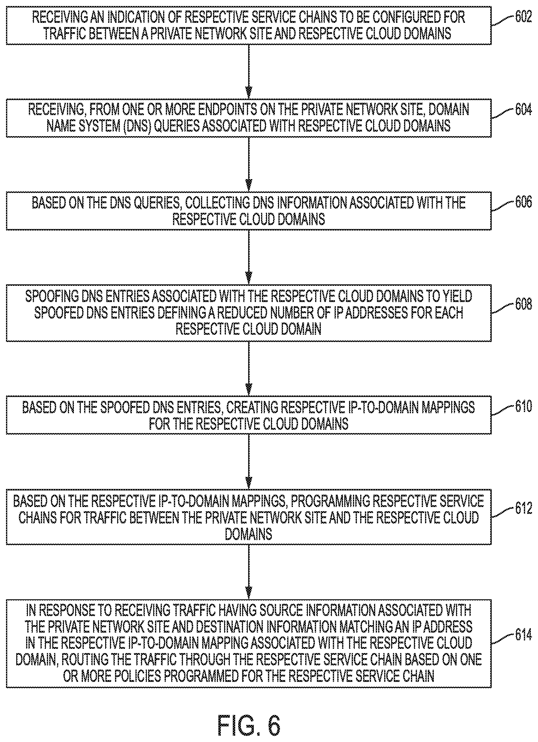
FIG. 6 illustrates an example method for creating service chains for inter-cloud traffic;
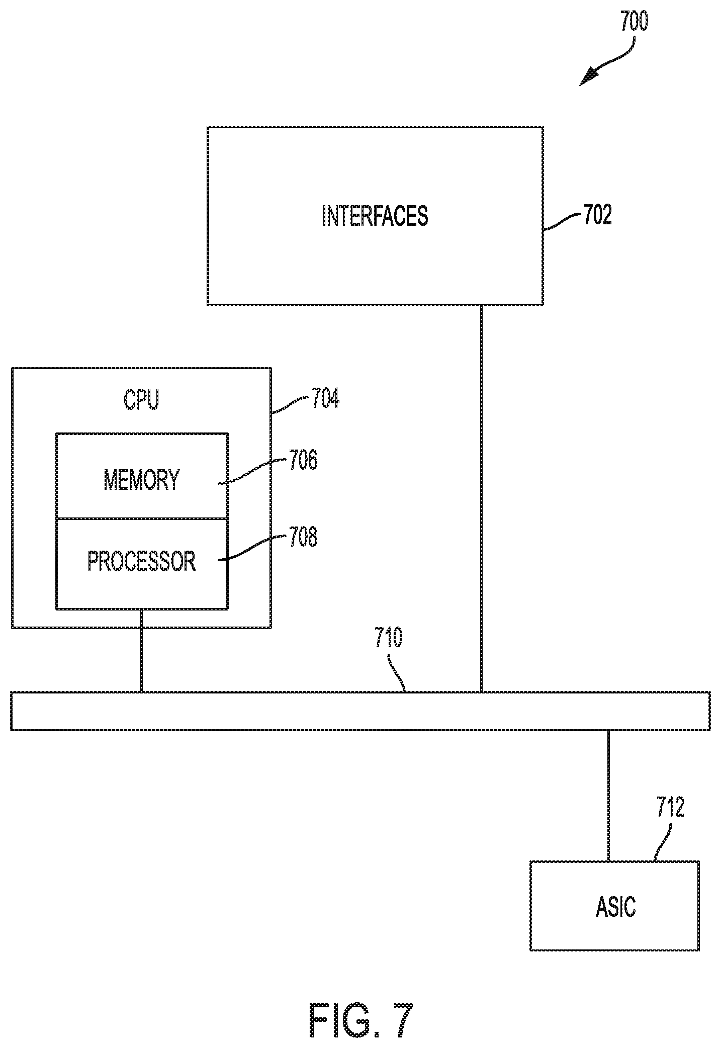
FIG. 7 illustrates an example network device for programming and applying service chains for inter-cloud traffic; and
FIG. 8 illustrates an example computing device architecture.
DETAILED DESCRIPTION
Various aspects of the disclosure are discussed in detail below. Features of one aspect may be applied to each aspect alone or in combination with other aspects. Moreover, while specific implementations are discussed, it should be understood that this is done for illustration purposes only. A person skilled in the relevant art will recognize that other components and configurations may be used without parting from the spirit and scope of the disclosure. Thus, the following description and drawings are illustrative and are not to be construed as limiting. Numerous specific details are described to provide a thorough understanding of the disclosure. However, in certain instances, well-known or conventional details are not described in order to avoid obscuring the description.
As used herein, "one embodiment" or "an embodiment" can refer to the same embodiment or any embodiment(s). Moreover, reference to "one embodiment" or "an embodiment" means that a particular feature, structure, or characteristic described in connection with the embodiment is included in at least one embodiment of the disclosure. The appearances of the phrase "in one embodiment" in various places in the specification are not necessarily all referring to the same embodiment, nor are separate or alternative embodiments mutually exclusive of other embodiments. Features described herein with reference to one embodiment can be combined with features described with reference to any embodiment.
The terms used in this specification generally have their ordinary meanings in the art, within the context of the disclosure and the specific context where each term is used. Alternative language and synonyms may be used for any one or more of the terms discussed herein, and no special significance should be placed upon whether or not a term is elaborated or discussed herein. In some cases, synonyms for certain terms are provided. A recital of one or more synonyms does not exclude the use of other synonyms. The use of examples anywhere in this specification, including examples of any terms discussed herein, is illustrative and not intended to limit the scope and meaning of the disclosure or any example term. Likewise, the disclosure is not limited to the specific embodiments or examples described in this disclosure.
Without an intent to limit the scope of the disclosure, examples of instruments, apparatus, methods and their related functionalities are provided below. Titles or subtitles may be used in the examples for convenience of a reader, and in no way should limit the scope of the disclosure. Unless otherwise defined, technical and scientific terms used herein have the meaning as commonly understood by one of ordinary skill in the art to which this disclosure pertains. In the case of a conflict, the present document and included definitions will control.
Additional features and advantages of the disclosure will be set forth in the description which follows, and in part will be recognized from the description, or can be learned by practice of the herein disclosed principles. The features and advantages of the disclosure can be realized and obtained by means of the instruments and combinations particularly pointed out herein. These and other features of the disclosure will become more fully apparent from the following description and appended claims, or can be learned by the practice of the principles set forth herein.
Overview
Disclosed are systems, methods, and computer-readable media for creating service chains for inter-cloud traffic. In some examples, a system, such as a switch, can receive an indication of respective service chains to be configured for traffic between a private network site (e.g., private cloud or data center) and respective cloud domains (e.g., public clouds). The indication can be specified by a cloud consumer/customer, and can define the respective service chains, including the services in the respective service chains, and the destination cloud domains associated with the respective service chains.
The system can receive, from one or more endpoints (e.g., servers, applications, devices, etc.) on the private network site, domain name system (DNS) queries associated with respective cloud domains. The system can forward the DNS queries associated with the respective cloud domains to one or more DNS servers and receive one or more DNS resolution results from the one or more DNS servers. The system can send, to the one or more endpoints on the private network site, one or more DNS responses to the DNS queries, which can identify one or more IP addresses associated with the respective cloud domains.
Based on the DNS queries, the system can collect DNS information associated with the respective cloud domains. In some examples, the system can snoop the DNS queries and/or associated DNS resolution results to identify IP information corresponding to the respective cloud domains. Moreover, the system can spoof DNS entries associated with the respective cloud domains. The spoofed DNS entries can define a reduced number of IP addresses for each respective cloud domain. The reduced number of IP addresses is smaller than a total number of IP addresses allocated/registered to the respective cloud domain. In some examples, the reduced number of IP addresses associated with the respective cloud domain can be a subset of the total number of IP addresses allocated to the respective cloud domain. The subset of the total number of IP addresses allocated to the respective cloud domain can be identified or selected from the one or more DNS resolution results.
Based on the spoofed DNS entries, the system can create respective IP-to-domain mappings for the respective cloud domains. Each respective IP-to-domain mapping can associate the respective cloud domain with an IP address from the reduced number of IP addresses associated with the respective cloud domain. The IP address can be, for example, a virtual or private IP address allocated by the system for the respective cloud domain or a public IP registered to the respective cloud domain and identified by snooping the DNS resolution results associated with the DNS queries.
Based on the respective IP-to-domain mappings, the system can program the respective service chains for traffic between the private network site and the respective cloud domains. Each respective service chain can be programmed for traffic from the private network site or a segment from the private network site (e.g., one or more endpoints in the private network site), as well as a respective cloud domain or cloud domain service.
Moreover, each respective service chain can be programmed on hardware (e.g., TCAM) via one or more policies (e.g., Access Control List entries) configured to route, through the respective service chain, traffic having source information associated with the private network site (e.g., an IP or subnet associated with the private network site and/or one or more endpoints in the private network site) and destination information matching the IP address in the respective IP-to-domain mapping associated with the respective cloud domain. In some cases, programming the respective service chains can include programming respective cloud service names for the respective cloud services and associating at least one of the respective service chains or the IP-to-domain mappings with the respective cloud service names.
When the system receives traffic, it can perform a lookup to determine if the traffic matches any of the programmed service chains. For example, the system can compare header information in the traffic (e.g., 5-tuple including source and destination information) with ACL entries programmed on the system for the respective service chains. Each ACL entry can specify a source (e.g., source IP or subnet), a destination (e.g., destination IP), a protocol, an application or service name, an action for redirecting the traffic to an associated service, etc. The system can thus use the header information in the traffic and the traffic information in the ACL entries to determine which, if any, ACL entries match the traffic and determine what action should be taken for the traffic.
When the traffic received has source information associated with the private network site (e.g., an IP or subnet associated with the private network site) and destination information matching the IP address in the respective IP-to-domain mapping associated with the respective cloud domain, the system can route the traffic through the respective service chain based on the one or more policies (e.g., ACL entries) associated with respective service chain. The system can redirect the traffic to each service in the respective service chain based on the programmed entries or policies for that service chain. Once the traffic has been processed through every service in the service chain, the system can send the traffic to the destination cloud domain.
DESCRIPTION OF EXAMPLE EMBODIMENTS
Disclosed herein are techniques for creating service chains for inter-cloud traffic. These techniques allow service chains to be configured based on both the origin cloud or network and the destination cloud or cloud service. The service chains can be configured on network devices for specific inter-cloud traffic using a reduced number of addresses for each cloud domain. As previously mentioned, cloud providers and services typically have a very large number of IP addresses allocated to them. Moreover, network devices have limited storage and memory resources, such as TCAM, which are insufficient to implement service chains for each IP allocated to a cloud provider or service. This problem is compounded when dealing with inter-cloud traffic, which typically involves an even higher number of IP addresses associated with the service chain. As a result, network devices generally do not have sufficient capacity to implement service chains for traffic between each origin and destination cloud IP. Consequently, network operators cannot program service chains on the network device based on the origin and destination clouds of inter-cloud traffic.
To overcome these limitations, the techniques herein can reduce the number of inter-cloud addresses used to program service chains for inter-cloud traffic on the network device. Each cloud domain can be mapped to a reduced number of addresses which can be used to program service chains on the network device for specific inter-cloud traffic without exceeding the hardware capabilities of the network device. The reduced number of addresses thus allows service chains to be programmed on the network device's hardware based on the origin and/or destination clouds or services of the inter-cloud traffic.
The service chains may be programmed on hardware access control lists (ACLs) on the network device. For example, the service chains can be programmed on ACLs in the network device's TCAM. The ACLs can include deterministic entries for each cloud domain and/or service, which define actions to be selectively applied to matching inter-cloud traffic. If the network device receives traffic matching an ACL entry, the network device can route the traffic to a particular service application in a service chain based on the action defined in the ACL entry. The ACL entries and reduced number of inter-cloud addresses allow service chains for inter-cloud traffic to be programmed directly on the network device, despite the limited hardware capabilities of the network device. The technologies herein also provide a paradigm for programming cloud service names used for the service chains natively on the network device.
The disclosure now turns to FIG. 1, which illustrates an example service chain configuration 100 for application traffic. In this example, a service chain 102 is configured to process traffic between endpoint 104 and endpoint 106. The endpoint 104 can include any device or server (physical and/or virtual) on a network, such as a cloud consumer network (e.g., a private cloud or on-premises site), and endpoint 106 can include any device or server (physical and/or virtual) on a different network, such as a public cloud. For example, endpoint 104 can be an application or server on a private cloud and endpoint 106 can be an application or server on a public cloud.
The service chain 102 includes service applications 112, 114, 116, which may be configured to apply specific L4 (Layer 4) through L7 (Layer 7) policies to traffic between endpoint 104 and endpoint 106. The service applications 112, 114, 116 can be implemented via respective virtual machines (VMs), software containers, servers, nodes, clusters of nodes, data centers, etc. Example service applications (112, 114, 116) include, without limitations, firewalls, Intrusion Detection Systems (IDS), Intrusion Prevention Systems (IPS), WAN Optimizers, Network Address Translation (NAT) systems, virtual routers/switches, load balancers, Virtual Private Network (VPN) gateways, data loss prevention (DLP) systems, web application firewalls (WAFs), application delivery controllers (ADCs), packet capture appliances, secure sockets layer (SSL) appliances, adaptive security appliances (ASAs), etc.
The service applications 112, 114, 116 in the service chain 102 are interconnected via a logical link 108A, which is supported by a physical link 108B through physical infrastructure 110. The physical infrastructure 110 can include one or more networks, nodes, data centers, clouds, hardware resources, physical locations, etc. Traffic from endpoint 104 can be routed to the physical infrastructure 110 through the physical link 108B, and redirected by the physical infrastructure 110 along the logical link 108A and through the service chain 102.
FIG. 2A illustrates a first example configuration 200 of service chains 208A-N, 236A-N for traffic between a cloud consumer 202 and cloud providers 232. The consumer 202 represents a cloud customer or consumer network, such as a private cloud, network, data center, etc. The cloud providers 232 represent public clouds hosting applications, services, and/or resources consumed by the cloud consumer 202. The cloud consumer 202 and cloud providers 232 can communicate via routed core 230. Routed core 230 can represent one or more networks, clouds, data centers, routers, etc. For example, routed core 230 can represent an inter-cloud fabric capable of routing traffic between the cloud consumer 202 and the cloud providers 232.
The consumer 202 includes endpoints 204 which represent applications and/or servers hosted by the consumer 202 (e.g., on the consumer's network(s)). In this example, the endpoints 204 include sales applications 204A, finance applications 204B, and human resources (HR) applications 204N. The applications 204 can be hosted on specific servers and/or network segments of the consumer 202.
The configuration 200 includes consumer-side service chains 206 including service chains 208A-N (collectively "208") configured for traffic from the endpoints 204 to the cloud providers 232. The service chains 208 process traffic between the endpoints 204 and the routed core 230, prior to being routed by the routed core 230 to the cloud providers 232.
The service chains 208 include application services 210 configured to apply respective L4-L7 policies to traffic from the endpoints 204. For example, service chain 208A includes service applications 210, 212, 214 for traffic associated with the sales applications 204A. In this example, traffic from the sales applications 204A is first processed by service application 210 in the service chain 208A, which can be, for example, a perimeter firewall. The traffic is then processed by service application 212 in the service chain 208A, which can be, for example, a VPN gateway. The traffic is finally processed by service application 214 in the service chain 208A, which can be, for example, an application firewall (e.g., database firewall). Once the traffic is processed by service application 214, it is sent to the routed core 230, which subsequently routes the traffic to a particular cloud from the cloud providers 232.
Similarly, service chain 208B includes service applications 216, 218, 220 for traffic associated with the finance applications 204B. In this example, traffic from the finance applications 204B is first processed by service application 216 in the service chain 208B, which can be, for example, a perimeter firewall. The traffic is then processed by service application 218 in the service chain 208B, which can be, for example, a VPN gateway. The traffic is finally processed by service application 220 in the service chain 208A, which can be, for example, an application firewall. Once the traffic is processed by service application 220, it is sent to the routed core 230, which subsequently routes the traffic to a particular cloud from the cloud providers 232.
Service chain 208N includes service applications 222, 224, 226, 228 for traffic associated with the HR applications 204N. In this example, traffic from the HR applications 204N is first processed by service application 222 in the service chain 208N, which can be, for example, a perimeter firewall. The traffic is then processed by service application 218 in the service chain 208N, which can be, for example, a load balancer. The traffic is next processed by service application 226 in the service chain 208N, which can be, for example, a Web appliance. The traffic is finally processed by service application 228 in the service chain 208N, which can be, for example, an application firewall. Once the traffic is processed by service application 228, it is sent to the routed core 230, which subsequently routes the traffic to a particular cloud from the cloud providers 232.
As illustrated in FIG. 2A, the number, type and sequence of appliances in the service chains 208A-N can vary. Each service chain (208A-N) can be customized for the specific traffic associated with the applications 204A-N. Moreover, the service chains 208A-N can represent a logical path (e.g., 108A) for the traffic from the applications 204A-N, which can be supported by infrastructure (e.g., 110) along a physical path (e.g., 108B).
The configuration 200 also includes provider-side service chains 234 between the routed core 230 and the cloud providers 232. The provider-side service chains 234 can process traffic exchanged between the routed core 230 and the cloud providers 232. The provider-side service chains 234 in this example include service chains 236 A-N (collectively "236"). Each of the service chains 236 corresponds to a particular cloud 232A-N.
For example, service chain 236A corresponds to cloud 232A, and includes service applications 238, 240, 242. Service applications 238, 240, 242 process traffic between the routed core 230 and cloud 232A. In this example, service applications 238, 240, 242 represent a perimeter firewall, a load balancer, and an application firewall (e.g., database firewall, Web firewall, etc.).
Service chain 236B corresponds to cloud 232B, and includes service applications 244 and 246. Service applications 244 and 246 process traffic between the routed core 230 and cloud 232B. In this example, service applications 244 and 246 represent a firewall and a load balancer.
Service chain 236C corresponds to cloud 232C, and includes service applications 248 and 250. Service applications 248 and 250 process traffic between the routed core 230 and cloud 232C. In this example, service applications 248 and 250 represent an IPS and a firewall.
Service chain 236N corresponds to cloud 232N, and includes service applications 252, 254, 256. Service applications 252, 254, 256 process traffic between the routed core 230 and cloud 232N. In this example, service applications 252, 254, 256 represent a perimeter firewall, an SSL appliance, and a load balancer.
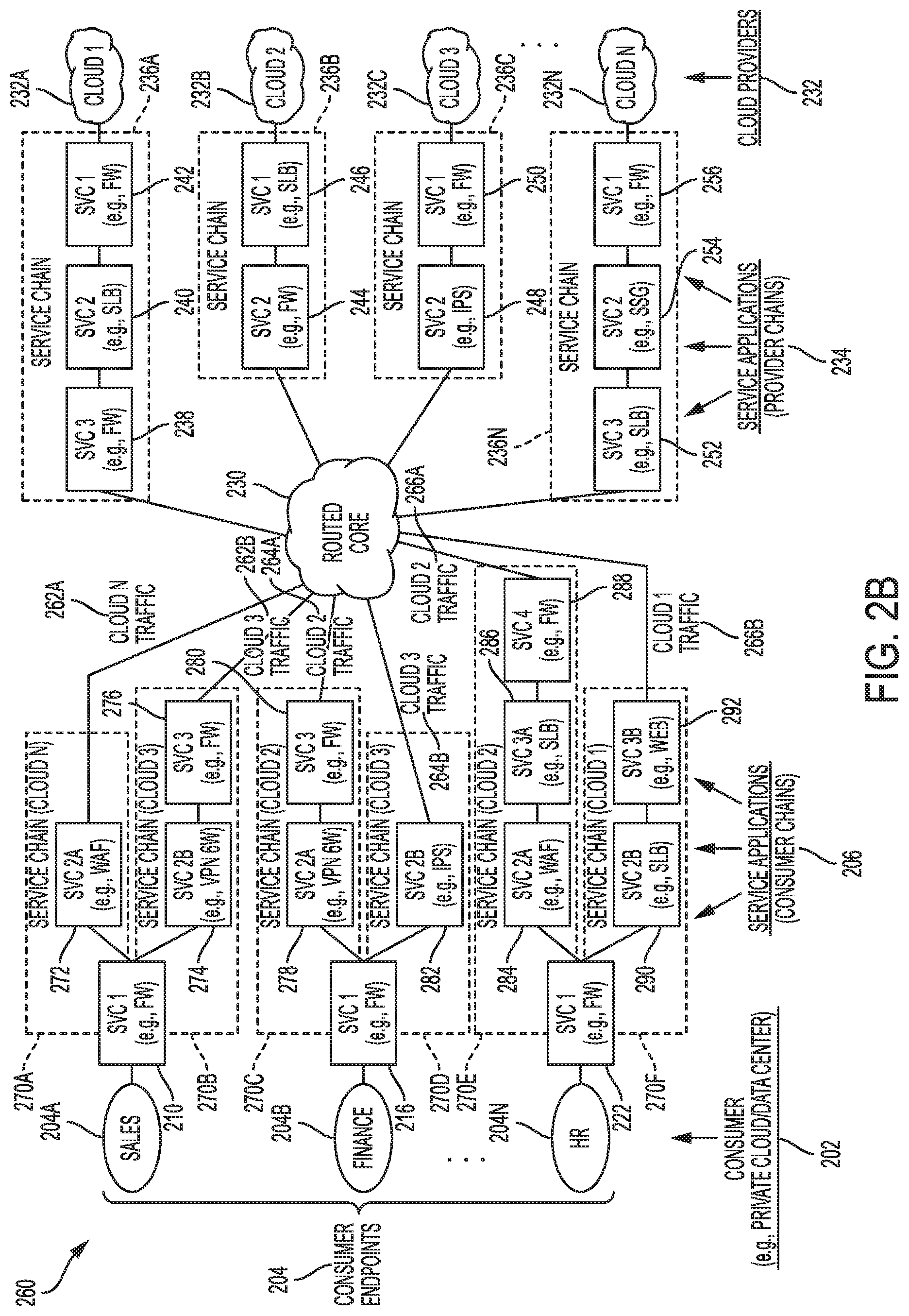
FIG. 2B illustrates another example configuration 260 of service chains for traffic between cloud consumer 202 and cloud providers 232. In this example, configuration 260 includes different consumer-side service chains 270 configured based on the respective origin (e.g., applications 204A-N on the consumer 202) and destination cloud (e.g., 232A-N) of the traffic. Unlike configuration 200 shown in FIG. 2A, which applies the same service chains to all traffic of a particular consumer endpoint (e.g., applications 204A-N) irrespective of the cloud destination (e.g., 232A-N), configuration 260 can apply different service chains to traffic from the same consumer endpoint depending on the cloud destination associated with the traffic.
The consumer-side service chains 270 in configuration 260 are deterministically applied to traffic based on a match of the traffic origin (e.g., application 204A, 204B, or 204N) and the traffic destination (e.g., cloud 232A, 232B, 232C, or 232N). The different consumer-side service chains 270 are thus configured specifically based on the respective traffic origin at the consumer 202 and destination clouds. The different consumer-side service chains 270 can be programmed on hardware (e.g., TCAM) as described herein, despite the large number of addresses allocated to the consumer 202 and each of the cloud providers 232.
To illustrate, service chain 270A is configured specifically for traffic 262A between sales applications 204A and cloud 232N. In this example, service chain 270A includes service application 210 (e.g., perimeter firewall) and service application 272 (e.g., web application firewall (WAF)). Service chain 270B is configured specifically for traffic 262B between the sales applications 204A and cloud 232C. In this example, service chain 270B includes service application 210 (e.g., perimeter firewall), service application 274 (e.g., VPN gateway), and service application 276 (e.g., application firewall). As illustrated by service chains 270A and 270B, traffic associated with the sales applications 204A can be routed through different service chains depending on the destination cloud associated with the traffic.
Service chain 270C is configured specifically for traffic 264A between finance applications 204B and cloud 232B. In this example, service chain 270C includes service application 216 (e.g., perimeter firewall), service application 278 (e.g., VPN gateway), and service application 280 (e.g., application firewall). Service chain 270D is configured specifically for traffic 264B between the finance applications 204B and cloud 232C. In this example, service chain 270D includes service application 216 (e.g., perimeter firewall) and service application 282 (e.g., IPS).
Service chain 270E is configured specifically for traffic 266A between HR applications 204N and cloud 232B. In this example, service chain 270E includes service application 222 (e.g., perimeter firewall), service application 284 (e.g., WAF), service application 286 (e.g., load balancer), and service application 288 (e.g., application firewall). Service chain 270F is configured specifically for traffic 266B between the HR applications 204N and cloud 232A. In this example, service chain 270F includes service application 222 (e.g., perimeter firewall), service application 290 (e.g., load balancer), and service application 292 (e.g., Web appliance).
As illustrated in FIG. 2B, the number, type and sequence of appliances in the consumer-side service chains 270 can vary. Each service chain (270A-F) can be customized based on the traffic origin (e.g., applications 204A-N at the consumer 202) and the traffic destination (e.g., clouds 232A-N). Moreover, the consumer-side service chains 270 can represent a logical path (e.g., 108A) for the traffic from the applications 204A-N, which can be supported by infrastructure (e.g., 110) along a physical path (e.g., 108B).
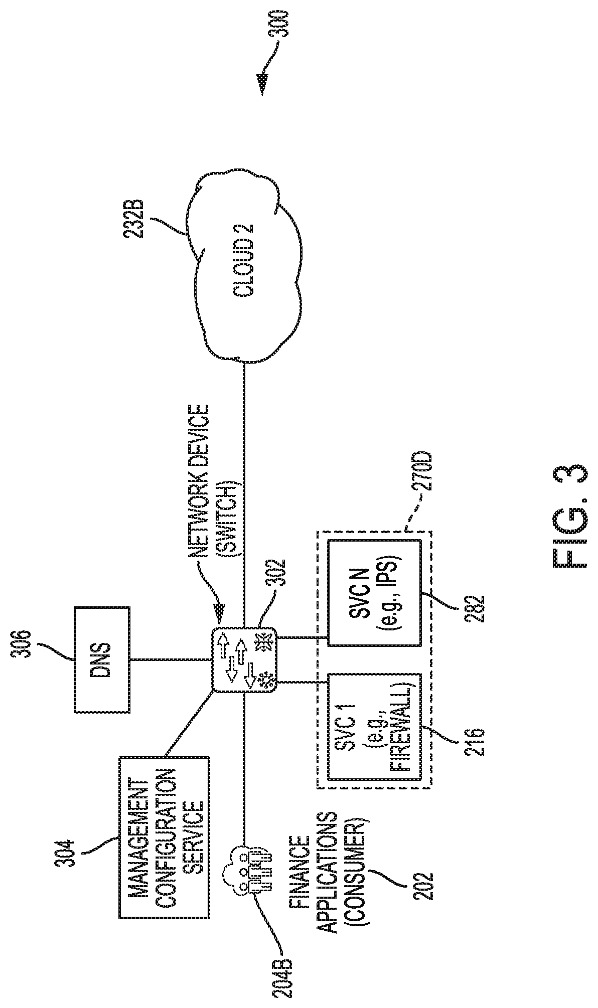
FIG. 3 illustrates a diagram of an example architecture 300 for configuring a network device to perform service chaining for inter-cloud traffic. The architecture 300 includes a network device 302, such as a switch, for routing inter-cloud traffic through specific service chains configured and applied based on the traffic origin (e.g., consumer 202) and the traffic destination cloud (e.g., cloud providers 232). In this example, network device 302 is programmed to route traffic between finance applications 204B and cloud 232B through service chain 270D, which includes service applications 216, 282. The service chain 270D can be programmed on hardware of the network device 302. For example, the service chain 270D can be programmed on an ACL in TCAM on the network device 302.
To program the service chain 270D, a management configuration service 304 can communicate with the network device 302 to specify the service chain(s) (e.g., 270D) and endpoints (e.g., 204B and 232B) for the service chain(s). The service chain(s) and endpoint can be defined by the consumer 202. Moreover, the endpoints can reside in different clouds. The network device 302 can then build the service chain(s) to ensure that traffic between specific consumer segments (e.g., endpoints 204) and cloud services (e.g., clouds 232A-N) are redirected to respective L4-L7 service chains.
In some cases, the consumer 202 can access an interface via the management configuration service 304 where the consumer 202 can specify the destination domains (e.g., clouds 232A-N) corresponding to the service chains they want to create for specific application traffic. The consumer 202 can also specify the consumer applications or endpoints associated with the service chains. The consumer applications or endpoints (e.g., applications 204A-N) can be identified based on respective network addressing information. For example, the consumer applications or endpoints can be identified by their corresponding IP subnets.
In this example, the consumer 202 specifies service chain 270D, which includes service applications 216 and 282, and identifies finance applications 204B and cloud 232B for the service chain 270D. The network device 302 will then create, as described below, the service chain 270D and deterministically apply it to traffic between the finance applications 204B and cloud 232B.
The network device 302 can be configured to communicate with DNS server 306 to forward DNS queries from the consumer 202. In some examples, the DNS server 306 can be an OPEN DNS server. When the network device 302 receives a DNS request from the finance applications 204B, it can forward the DNS request to the DNS server 306. The DNS request can identify the domain name of the cloud 232B (and/or a cloud service associated with the cloud 232B), and request an IP address to communicate with the cloud 232B. The DNS server 306 identifies an IP address allocated to the cloud 232B and returns a DNS resolution response identifying the IP address associated with the domain name.
The network device 302 then receives the DNS resolution response from the DNS server 306. The network device 302 can snoop the DNS request and the DNS resolution response to build a cache of domain-to-IP mappings for the cloud 232B. To reduce the number of hardware entries or policies (e.g., TCAM entries) needed to program the service chain 270D on the network device 302, the network device 302 can use a subset of IP addresses for the cloud 232B, rather than creating an entry for each IP of the cloud 232B. As previously explained, the number of IP addresses allocated to the cloud 232B can be very large. Therefore, programming an entry on the network device 302 for each IP of the cloud 232B can be expensive and even prohibitive. Accordingly, the network device 302 can scale the service chaining to a smaller subset of IP addresses.
The subset of IP addresses can include one or more IP addresses allocated to the cloud 232B and identified by snooping the DNS requests from the consumer 202, or a single virtual IP (VIP). For example, in some implementations, the network device 302 can allocate a VIP for each cloud and use the VIP to program hardware entries for the respective service chains. The network device 302 can then match traffic from the consumer 202 to a specific service chain based on the traffic source (e.g., IP or subnet associated with the consumer 202 or consumer endpoint 204) and the VIP allocated to the destination cloud. The network device 302 can redirect the traffic to the service applications associated with the specific service chain and perform a destination network address translation (NAT) to then route the traffic to the destination cloud.
To illustrate, the network device 302 can allocate a VIP to cloud 232B and use the VIP and an address associated with the finance applications 204B, such as a subnet IP, to program TCAM entries for the service chain 270D. The network device can then use the addresses used to program the service chain 270D; namely, the VIP associated with the cloud 232B and the address associated with the finance applications 204B, to match traffic between the finance applications 204B and the cloud 232B with the TCAM entries associated with the service chain 270D and redirect the traffic accordingly.
In other implementations, the network device 302 can spoof the DNS entries associated with the destination cloud (e.g., 232B) and use a small subset of IP addresses allocated to the destination cloud (e.g., 232B) to program the hardware entries (e.g., TCAM entries) for the respective service chain (e.g., 270D). The subset of IP addresses can be determined by snooping the DNS requests as previously mentioned. The network device 302 can then use the subset of IP addresses to match traffic from the consumer 202 (e.g., finance applications 204B) to the destination cloud (e.g., 232B) with the hardware entries for the respective service chain (e.g., 270D) and redirect the traffic accordingly. Once the traffic is processed through the service chain, the network device 302 can route the traffic to the destination cloud (232B). In this example, NAT is not required to route the traffic to the destination cloud. Instead, the network device 302 can route the traffic to the destination cloud using the destination IP address associated with the traffic and the respective hardware entries.
Having programmed the service chain 270D on hardware based on the subset of IP addresses selected for the cloud 232B (e.g., the VIP assigned by the network device 302 to the cloud 232B or the subset of IP addresses allocated to the cloud 232B and identified based on DNS resolution results), the network device 302 can deterministically redirect traffic between the finance applications 204B and destination cloud 232B to the service chain 270D.
For example, when the network device 302 receives traffic from the finance applications 204B, it can perform a TCAM or hardware lookup using the source and destination address information in the packets. Based on the TCAM or hardware lookup, the network device 302 can find entries matching the source and destination address information in the packets, and redirect the packets through the service chain 270D as specified by the matching entries associated with the service chain 270D. After the packets are processed through the service chain 270D, the network device 302 can send the packets to the destination cloud 232B.
FIG. 4 illustrates example IP-to-domain mappings 400 for programming service chains for inter-cloud traffic. The IP-to-domain mappings 400 can map cloud application names 402 to internal IP mappings 404 and domain names 406. The cloud application names 402 can correspond to respective cloud services associated with the cloud providers 232 and the domain names 406 can correspond to the respective cloud services and cloud providers 232. The internal IP mappings 404 can include the subset of IP addresses allocated by the network device 302 to the domain names 406. For example, the internal IP mappings 404 can include respective VIPs or spoofed DNS entries for the domain names 406 (e.g., the subset of IP address associated with the clouds 232A-N).
To illustrate, in FIG. 4, the IP-to-domain mappings 400 include entries 408A-D for clouds 232A, 232B, and 232C. Entry 408A maps Cloud 1 (232A) Email Service to private IP 172.16.1.1 and domain name http://mail.cloud1.com. Entry 408B maps Cloud (232A) Productivity Service to private IP 172.16.1.2 and domain name http://productivity.cloud1.com. Entry 408C maps Cloud 2 (232B) Service to private IP 172.16.1.3 and domain name http://cloud2.com. Entry 408D maps Cloud 3 (232C) Service to private IP 172.16.1.4 and domain name cloud3.com. Entries 408A-D in the IP-to-domain mappings 400 can then be used to program service chains for inter-cloud traffic, as illustrated in FIG. 5.
FIG. 5 illustrates example service chain definitions 500 for inter-cloud traffic and hardware ACL 510 programmed on network device 302 to build service chains according to the service chain definitions 500. The service chain definitions 500 identify service chains 502, 504 defined for specific inter-cloud traffic.
Service chain 502 includes an indication 502A of the traffic associated with the service chain 502. The indication 502A specifies that the service chain 502 corresponds to traffic between finance applications 204B associated with consumer 202 and cloud 232B (e.g., Cloud 2). The service chain 502 also includes rules 502B for building the service chain 502.
The rules 502B identify actions to be performed for traffic matching 5-tuple A associated with the finance applications 204B and cloud 232B. The 5-tuple A can include the origin IP/subnet of the traffic, the origin port number of the traffic, the destination IP of the traffic, the destination port of the traffic, and the application service or protocol associated with the traffic. In this example, the 5-tuple A includes the IP or IP subnet associated with the finance applications 204B as the source and the IP allocated by the network device 302 to the cloud 232B (e.g., IP 172.16.1.3 from entry 408C in the internal IP mapping 404 shown in FIG. 4) as the destination.
In this example, the rules 502B indicate that traffic matching 5-tuple A associated with the finance applications 204B and cloud 2 (232B) should first be sent to Service 1 (e.g., 216), which in this example is a perimeter firewall. The rules 502B further indicate that traffic matching 5-tuple A should then be sent to Service 2 (e.g., 278), which in this example is a VPN gateway. The rules 502B indicate that traffic matching 5-tuple A should next be sent to Service 3 (e.g., 280), which in this example is an application firewall. The rules 502B finally indicate that after being processed by Service 3 (e.g., 280), the traffic matching 5-tuple A should be sent to the destination (e.g., cloud 232B).
Service chain 504 includes an indication 504A of the traffic associated with the service chain 504. The indication 504A specifies that the service chain 504 corresponds to traffic between finance applications 204B associated with consumer 202 and cloud 232C (e.g., Cloud 3). The service chain 504 also includes rules 504B for building the service chain 504.
The rules 504B identify actions to be performed for traffic matching 5-tuple B associated with the finance applications 204B and cloud 232C (e.g., Cloud 3). The 5-tuple B can include the origin
References
-
en.wikipedia.org/w/index.php?title=CEA-708&oldid=523143431
-
cloud.google.com/functions/docs/concepts/overview
-
-
-
developersidgerun
-
erg
-
-
usenix
-
tools.ietf.org/pdf/draft-ietf-dots-requirernents-01.pdf
-
developer.ibm.com/open/2016/02/22/openwhisk-a-quick-tech-preview
-
-
-
techcrunch.com/2016/08/03/what-real-cloud-native-apps-will-look-like
-
mail.cloud1.com
-
productivity.cloud1.com
-
cloud2.com
D00000
D00001
D00002
D00003
D00004
D00005
D00006
D00007
D00008
D00009
XML
uspto.report is an independent third-party trademark research tool that is not affiliated, endorsed, or sponsored by the United States Patent and Trademark Office (USPTO) or any other governmental organization. The information provided by uspto.report is based on publicly available data at the time of writing and is intended for informational purposes only.
While we strive to provide accurate and up-to-date information, we do not guarantee the accuracy, completeness, reliability, or suitability of the information displayed on this site. The use of this site is at your own risk. Any reliance you place on such information is therefore strictly at your own risk.
All official trademark data, including owner information, should be verified by visiting the official USPTO website at www.uspto.gov. This site is not intended to replace professional legal advice and should not be used as a substitute for consulting with a legal professional who is knowledgeable about trademark law.