In-memory service with plural buffer type assignment
Oravivattanakul , et al.
U.S. patent number 10,664,192 [Application Number 15/963,341] was granted by the patent office on 2020-05-26 for in-memory service with plural buffer type assignment. This patent grant is currently assigned to SALESFORCE.COM, INC.. The grantee listed for this patent is salesforce.com, inc.. Invention is credited to Samarpan Jain, Choapet Oravivattanakul.


View All Diagrams
| United States Patent | 10,664,192 |
| Oravivattanakul , et al. | May 26, 2020 |
In-memory service with plural buffer type assignment
Abstract
In an example, a computing system is configured to detect data to temporarily store in a group of buffers using an in-memory buffer service; correlate, to the detected data, one or more identifiers of a plurality of identifiers based on a characteristic of the detected data, wherein a first identifier of the plurality corresponds to a first buffer type and a second different identifier of the plurality corresponds to a second buffer type; in response to the data correlated to a single identifier of the identifiers, create a first data object and place the first data object in one of the buffers of the corresponding buffer type; and in response to the data correlated to more than one of the identifiers, create a second data object for each one of the identifiers and place the second data objects in ones of the buffers of the corresponding buffer types, respectively.
| Inventors: | Oravivattanakul; Choapet (San Francisco, CA), Jain; Samarpan (San Francisco, CA) | ||||||||||
|---|---|---|---|---|---|---|---|---|---|---|---|
| Applicant: |
|
||||||||||
| Assignee: | SALESFORCE.COM, INC. (San
Francisco, CA) |
||||||||||
| Family ID: | 68292584 | ||||||||||
| Appl. No.: | 15/963,341 | ||||||||||
| Filed: | April 26, 2018 |
Prior Publication Data
| Document Identifier | Publication Date | |
|---|---|---|
| US 20190332315 A1 | Oct 31, 2019 | |
| Current U.S. Class: | 1/1 |
| Current CPC Class: | G06F 3/061 (20130101); G06F 3/0656 (20130101); G06F 3/0604 (20130101); G06F 3/067 (20130101); G06F 3/0673 (20130101) |
| Current International Class: | G06F 3/06 (20060101) |
References Cited [Referenced By]
U.S. Patent Documents
| 5577188 | November 1996 | Zhu |
| 5608872 | March 1997 | Schwartz et al. |
| 5649104 | July 1997 | Carleton et al. |
| 5715450 | February 1998 | Ambrose et al. |
| 5761419 | June 1998 | Schwartz et al. |
| 5819038 | October 1998 | Carleton et al. |
| 5821937 | October 1998 | Tonelli et al. |
| 5831610 | November 1998 | Tonelli et al. |
| 5873096 | February 1999 | Lim et al. |
| 5918159 | June 1999 | Fomukong et al. |
| 5963953 | October 1999 | Cram et al. |
| 5983227 | November 1999 | Nazem et al. |
| 6092083 | July 2000 | Brodersen et al. |
| 6161149 | December 2000 | Achacoso et al. |
| 6169534 | January 2001 | Raffel et al. |
| 6178425 | January 2001 | Brodersen et al. |
| 6189011 | February 2001 | Lim et al. |
| 6216133 | April 2001 | Masthoff |
| 6216135 | April 2001 | Brodersen et al. |
| 6233617 | May 2001 | Rothwein et al. |
| 6236978 | May 2001 | Tuzhilin |
| 6266669 | July 2001 | Brodersen et al. |
| 6288717 | September 2001 | Dunkle |
| 6295530 | September 2001 | Ritchie et al. |
| 6324568 | November 2001 | Diec et al. |
| 6324693 | November 2001 | Brodersen et al. |
| 6336137 | January 2002 | Lee et al. |
| D454139 | March 2002 | Feldcamp et al. |
| 6367077 | April 2002 | Brodersen et al. |
| 6393605 | May 2002 | Loomans |
| 6405220 | June 2002 | Brodersen et al. |
| 6411949 | June 2002 | Schaffer |
| 6434550 | August 2002 | Warner et al. |
| 6446089 | September 2002 | Brodersen et al. |
| 6535909 | March 2003 | Rust |
| 6549908 | April 2003 | Loomans |
| 6553563 | April 2003 | Ambrose et al. |
| 6560461 | May 2003 | Fomukong et al. |
| 6574635 | June 2003 | Stauber et al. |
| 6577726 | June 2003 | Huang et al. |
| 6601087 | July 2003 | Zhu et al. |
| 6604117 | August 2003 | Lim et al. |
| 6604128 | August 2003 | Diec et al. |
| 6609150 | August 2003 | Lee et al. |
| 6621834 | September 2003 | Scherpbier et al. |
| 6654032 | November 2003 | Zhu et al. |
| 6665648 | December 2003 | Brodersen et al. |
| 6665655 | December 2003 | Warner et al. |
| 6684438 | February 2004 | Brodersen et al. |
| 6711565 | March 2004 | Subramaniam et al. |
| 6724399 | April 2004 | Katchour et al. |
| 6728702 | April 2004 | Subramaniam et al. |
| 6728960 | April 2004 | Loomans et al. |
| 6732095 | May 2004 | Warshaysky et al. |
| 6732100 | May 2004 | Brodersen et al. |
| 6732111 | May 2004 | Brodersen et al. |
| 6754681 | June 2004 | Brodersen et al. |
| 6763351 | July 2004 | Subramaniam et al. |
| 6763501 | July 2004 | Zhu et al. |
| 6768904 | July 2004 | Kim |
| 6772229 | August 2004 | Achacoso et al. |
| 6782383 | August 2004 | Subramaniam et al. |
| 6804330 | October 2004 | Jones et al. |
| 6826565 | November 2004 | Ritchie et al. |
| 6826582 | November 2004 | Chatterjee et al. |
| 6826745 | November 2004 | Coker |
| 6829655 | December 2004 | Huang et al. |
| 6842748 | January 2005 | Warner et al. |
| 6850895 | February 2005 | Brodersen et al. |
| 6850949 | February 2005 | Warner et al. |
| 6907566 | June 2005 | McElfresh et al. |
| 7062502 | June 2006 | Kesler |
| 7069231 | June 2006 | Cinarkaya |
| 7069497 | June 2006 | Desai |
| 7100111 | August 2006 | McElfresh et al. |
| 7181758 | February 2007 | Chan |
| 7269590 | September 2007 | Hull et al. |
| 7289976 | October 2007 | Kihneman et al. |
| 7340411 | March 2008 | Cook |
| 7356482 | April 2008 | Frankland et al. |
| 7373599 | May 2008 | McElfresh et al. |
| 7401094 | July 2008 | Kesler |
| 7406501 | July 2008 | Szeto et al. |
| 7412455 | August 2008 | Dillon |
| 7454509 | November 2008 | Boulter et al. |
| 7508789 | March 2009 | Chan |
| 7599935 | October 2009 | La Rotonda et al. |
| 7603331 | October 2009 | Tuzhilin et al. |
| 7603483 | October 2009 | Psounis et al. |
| 7620655 | November 2009 | Larsson et al. |
| 7644122 | January 2010 | Weyer et al. |
| 7668861 | February 2010 | Steven |
| 7698160 | April 2010 | Beaven et al. |
| 7730478 | June 2010 | Weissman |
| 7747648 | June 2010 | Kraft et al. |
| 7779039 | August 2010 | Weissman et al. |
| 7779475 | August 2010 | Jakobson et al. |
| 7827208 | November 2010 | Bosworth et al. |
| 7853881 | December 2010 | Aly Assal et al. |
| 7945653 | May 2011 | Zukerberg et al. |
| 8005896 | August 2011 | Cheah |
| 8014943 | September 2011 | Jakobson |
| 8015495 | September 2011 | Achacoso et al. |
| 8032297 | October 2011 | Jakobson |
| 8073850 | December 2011 | Hubbard et al. |
| 8082301 | December 2011 | Ahlgren et al. |
| 8095413 | January 2012 | Beaven |
| 8095531 | January 2012 | Weissman et al. |
| 8095594 | January 2012 | Beaven et al. |
| 8103611 | January 2012 | Tuzhilin et al. |
| 8150913 | April 2012 | Cheah |
| 8209308 | June 2012 | Rueben et al. |
| 8209333 | June 2012 | Hubbard et al. |
| 8275836 | September 2012 | Beaven et al. |
| 8457545 | June 2013 | Chan |
| 8484111 | July 2013 | Frankland et al. |
| 8490025 | July 2013 | Jakobson et al. |
| 8504945 | August 2013 | Jakobson et al. |
| 8510045 | August 2013 | Rueben et al. |
| 8510664 | August 2013 | Rueben et al. |
| 8566301 | October 2013 | Rueben et al. |
| 8646103 | February 2014 | Jakobson et al. |
| 9767022 | September 2017 | Pradeep et al. |
| 9767040 | September 2017 | Pradeep et al. |
| 2001/0044791 | November 2001 | Richter et al. |
| 2002/0072951 | June 2002 | Lee et al. |
| 2002/0082892 | June 2002 | Raffel et al. |
| 2002/0129352 | September 2002 | Brodersen et al. |
| 2002/0140731 | October 2002 | Subramaniam et al. |
| 2002/0143997 | October 2002 | Huang et al. |
| 2002/0162090 | October 2002 | Parnell et al. |
| 2002/0165742 | November 2002 | Robbins |
| 2003/0004971 | January 2003 | Gong |
| 2003/0018705 | January 2003 | Chen et al. |
| 2003/0018830 | January 2003 | Chen et al. |
| 2003/0066031 | April 2003 | Laane et al. |
| 2003/0066032 | April 2003 | Ramachandran et al. |
| 2003/0069936 | April 2003 | Warner et al. |
| 2003/0070000 | April 2003 | Coker et al. |
| 2003/0070004 | April 2003 | Mukundan et al. |
| 2003/0070005 | April 2003 | Mukundan et al. |
| 2003/0074418 | April 2003 | Coker et al. |
| 2003/0120675 | June 2003 | Stauber et al. |
| 2003/0151633 | August 2003 | George et al. |
| 2003/0159136 | August 2003 | Huang et al. |
| 2003/0187921 | October 2003 | Diec et al. |
| 2003/0189600 | October 2003 | Gune et al. |
| 2003/0204427 | October 2003 | Gune et al. |
| 2003/0206192 | November 2003 | Chen et al. |
| 2003/0225730 | December 2003 | Warner et al. |
| 2004/0001092 | January 2004 | Rothwein et al. |
| 2004/0010489 | January 2004 | Rio et al. |
| 2004/0015981 | January 2004 | Coker et al. |
| 2004/0027388 | February 2004 | Berg et al. |
| 2004/0128001 | July 2004 | Levin et al. |
| 2004/0186860 | September 2004 | Lee et al. |
| 2004/0193510 | September 2004 | Catahan et al. |
| 2004/0199489 | October 2004 | Barnes-Leon et al. |
| 2004/0199536 | October 2004 | Barnes-Leon et al. |
| 2004/0199543 | October 2004 | Braud et al. |
| 2004/0249854 | December 2004 | Barnes-Leon et al. |
| 2004/0260534 | December 2004 | Pak et al. |
| 2004/0260659 | December 2004 | Chan et al. |
| 2004/0268299 | December 2004 | Lei et al. |
| 2005/0050555 | March 2005 | Exley et al. |
| 2005/0091098 | April 2005 | Brodersen et al. |
| 2008/0249972 | October 2008 | Dillon |
| 2009/0063415 | March 2009 | Chatfield et al. |
| 2009/0100342 | April 2009 | Jakobson |
| 2009/0177744 | July 2009 | Marlow et al. |
| 2011/0218958 | September 2011 | Warshaysky |
| 2011/0247051 | October 2011 | Bulumulla |
| 2012/0042218 | February 2012 | Cinarkaya |
| 2012/0233137 | September 2012 | Jakobson et al. |
| 2012/0290407 | November 2012 | Hubbard et al. |
| 2013/0212497 | August 2013 | Zelenko et al. |
| 2013/0218948 | August 2013 | Jakobson |
| 2013/0218949 | August 2013 | Jakobson |
| 2013/0218966 | August 2013 | Jakobson |
| 2013/0247216 | September 2013 | Cinarkaya |
| 2014/0359537 | December 2014 | Jackobson et al. |
| 2016/0077798 | March 2016 | Pradeep |
| 2017/0060741 | March 2017 | Pradeep et al. |
| 2017/0060771 | March 2017 | Pradeep |
| 2017/0228409 | August 2017 | Darcy |
Other References
|
US. Appl. No. 62/051,107, entitled "Providing In-Memory Buffer Service", filed Sep. 16, 2014; 17 pages. cited by applicant. |
Primary Examiner: Tran; Denise
Attorney, Agent or Firm: Schwabe Williamson & Wyatt
Claims
What is claimed is:
1. A computing system, comprising: a processing system; and a memory device coupled to the processing system and including instructions stored thereon that, in response to execution by the processing system, are operable to perform operations including: detect data to temporarily store in a group of buffers using an in-memory buffer service; correlate, to the detected data, one or more identifiers of a plurality of identifiers based on a characteristic of the detected data, wherein a first identifier of the plurality of identifiers corresponds to a first buffer type of the group of buffers and a second different identifier of the plurality of identifiers corresponds to a second buffer type of the group of buffers, wherein the first buffer type is associated with a first flush policy and the second buffer type is associated with a second flush policy that is different than the first flush policy; in response to the data correlated to a single identifier of the identifiers, store the corresponding identifier in a first data object for the detected data to control placement of the first data object in one of the buffers of the corresponding buffer type; in response to the data correlated to more than one of the identifiers, store a different one of the more than one identifiers in each one of second data objects for the detected data to control placement of the second data objects in ones of the buffers of the corresponding buffer types, respectively; and identify a data object of the first data object or the second data objects and use the stored identifier of the identified data object to place the identified data object in one of the buffers of the group of buffers.
2. The computing system of claim 1, further comprising: create a plurality of identical data objects for the detected data to provide the second data objects; and wherein create the plurality of identical data objects is performed prior to store the different one of the more than one identifiers in each of the second data objects.
3. The computing system of claim 2, wherein the operations further include: create the first data object; and in response to the data correlated to the more than one of the identifiers, clone the first data object one or more times to create the plurality of identical data objects.
4. The computer system of claim 1, wherein the characteristic of the detected data comprises a characteristic of a plurality of predefined characteristics, and wherein the operations further include: create, at compile time, a mapping to associate the identifiers to the predefined characteristics; and match, at run time, the characteristic of the detected data to one of the predefined characteristics using the mapping, wherein correlate the one or more identifiers to the detected data is based on a result of the match.
5. The computer system of claim 4, wherein an output of the in-memory buffer service is coupled to a plural tenant database, and wherein the first buffer type corresponds to a first tenant of the plural tenant database and the second buffer type corresponds to a second different tenant of the plural tenant database.
6. The computer system of claim 5, wherein the mapping includes a first entry associating one of the identifiers to one of the predefined characteristics and a second entry associated a different one of the identifiers to the same one of the predefined characteristics, wherein one of the first and second entries specifies a tenant-based permission not specified by the other one of the first and second entries.
7. The computer system of claim 1, wherein the detected data comprises an event generated by a capture service, and wherein the data objects comprise event objects.
8. The computer system of claim 7, wherein the event comprises a login event, an API event, or a report event.
9. The computer system of claim 1, wherein the plurality of identifiers comprise bucket identifiers, wherein each bucket identifier corresponds to a different combination of one of the buffer types and one of a plurality of consumer chains.
10. The computer system of claim 9, wherein a first consumer chain of the plurality of consumer chains corresponds to one or more first transport destinations and a second consumer chain of the plurality of consumer chains corresponds to one or more second transport destinations, where at least one of the one or more first transport destinations is different than at least one of the one or more second transport destinations.
11. A computer implemented method, comprising: detecting data to temporarily store in a group of buffers using an in-memory buffer service; correlating, to the detected data, one or more identifiers of a plurality of identifiers based on a characteristic of the detected data, wherein a first identifier of the plurality of identifiers corresponds to a first buffer type of the group of buffers and a second different identifier of the plurality of identifiers corresponds to a second buffer type of the group of buffers, wherein the first buffer type is associated with a first flush policy and the second buffer type is associated with a second flush policy that is different than the first flush policy; in response to the data correlated to a single identifier of the identifiers, creating a first data object and placing the first data object in one of the buffers of the corresponding buffer type; and in response to the data correlated to more than one of the identifiers, creating a second data object for each identifier of the more than one of the identifiers and placing the second data objects in ones of the buffers of the corresponding buffer types, respectively.
12. The computer implemented method of claim 11, wherein the detected data comprises an event generated by a capture service, and wherein the data objects comprise event objects.
13. The computer implemented method of claim 12, wherein the event comprises a login event, an API event, or a report event.
14. The computer implemented method of claim 11, wherein the plurality of identifiers comprise bucket identifiers, wherein each bucket identifier corresponds to a different combination of one of the buffer types and one of a plurality of consumer chains.
15. The computer implemented method of claim 14, wherein a first consumer chain of the plurality of consumer chains corresponds to one or more first transport destinations and a second consumer chain of the plurality of consumer chains corresponds to one or more second transport destinations, where at least one of the one or more first transport destinations is different than at least one of the one or more second transport destinations.
16. A computing system, comprising: a processing system; and a memory device coupled to the processing system and including instructions stored thereon that, in response to execution by the processing system, are operable to perform operations including: detect data to temporarily store in a group of buffers using an in-memory buffer service; correlate, to the detected data, one or more identifiers of a plurality of identifiers based on a characteristic of the detected data, wherein a first identifier of the plurality of identifiers corresponds to a first buffer type of the group of buffers and a second different identifier of the plurality of identifiers corresponds to a second buffer type of the group of buffers, wherein the first buffer type is associated with a first flush policy and the second buffer type is associated with a second flush policy that is different than the first flush policy; in response to the data correlated to a single identifier of the identifiers, create a first data object and place the first data object in one of the buffers of the corresponding buffer type; and in response to the data correlated to more than one of the identifiers, create a second data object for each identifier of the more than one of the identifiers and place the second data objects in ones of the buffers of the corresponding buffer types, respectively.
17. The computing system of claim 16, wherein the operations further include: in response to the data correlated to a single identifier of the identifiers, store the identifier in the first data object to control the placement of the first data object in the one of the buffers of the corresponding buffer type; and in response to the data correlated to more than one of the identifiers, store a different one of the more than one identifiers in each one of the second data objects for the detected data to control the placement of the second data objects in the ones of the buffers of the corresponding buffer types, respectively.
18. The computing system of claim 17, wherein the operations further include: following placement of the first data object in one of the buffers of the corresponding buffer type or placement of the second data objects in the ones of the buffers of the corresponding buffer types, respectively, flush one of the data objects from one of the buffers; identify a consumer chain type based on the stored identifier of the flushed data object; and pass the data object to a consumer chain of consumer chains corresponding to client applications, respectively, based on the identified consumer chain type.
19. The computer system of claim 18, wherein the detected data comprises an event generated by a capture service, and wherein the data objects comprise event objects.
20. The computer system of claim 19, wherein the event comprises a login event, an API event, or a report event.
Description
COPYRIGHT NOTICE
A portion of the disclosure of this patent document contains material which is subject to copyright protection. The copyright owner has no objection to the facsimile reproduction by anyone of the patent document or the patent disclosure, as it appears in the United States Patent and Trademark Office patent file or records, but otherwise reserves all copyright rights whatsoever.
TECHNICAL FIELD
One or more implementations relate generally to computing systems, and some embodiments relate to an in-memory service with plural buffer type assignment.
DESCRIPTION OF THE RELATED ART
A data buffer is a region of physical memory storage used to temporarily store data while it is being moved from one place to another. In an application server implementing a data buffer, data objects may be stored in a buffer as they are retried from a client device or application before they are processed or sent elsewhere for more permanent storage. Buffers may be implemented in a fixed memory location in hardware, or by using a virtual data buffer in software, pointing at a location in the physical memory. Buffers are typically used when there is a difference between the rate at which data is received and the rate at which it can be processed, or in the case where these rates are variable. A buffer may be used to adjust timing by implementing a queue algorithm in memory, simultaneously wiring data into the queue at one rate and reading it at another rate.
BRIEF DESCRIPTION OF THE DRAWINGS
The included drawings are for illustrative purposes and serve to provide examples of possible structures and operations for the disclosed inventive systems, apparatus, methods and computer-readable storage media. These drawings in no way limit any changes in form and detail that may be made by one skilled in the art without departing from the spirit and scope of the disclosed implementations.
FIG. 1A shows a block diagram of an example environment in which an on-demand database service can be used according to some implementations.
FIG. 1B shows a block diagram of example implementations of elements of FIG. 1A and example interconnections between these elements according to some implementations.
FIG. 2 is a block diagram illustrating a computing environment with an in-memory buffer service, according to some implementations.
FIG. 3 is a block diagram illustrating an application server with an in-memory buffer service, according to some implementations.
FIG. 4 is a block diagram illustrating an application server with an in-memory buffer service, according to some implementations.
FIG. 5 is a block diagram illustrating an application server with dual in-memory bounded buffers, according to some implementations.
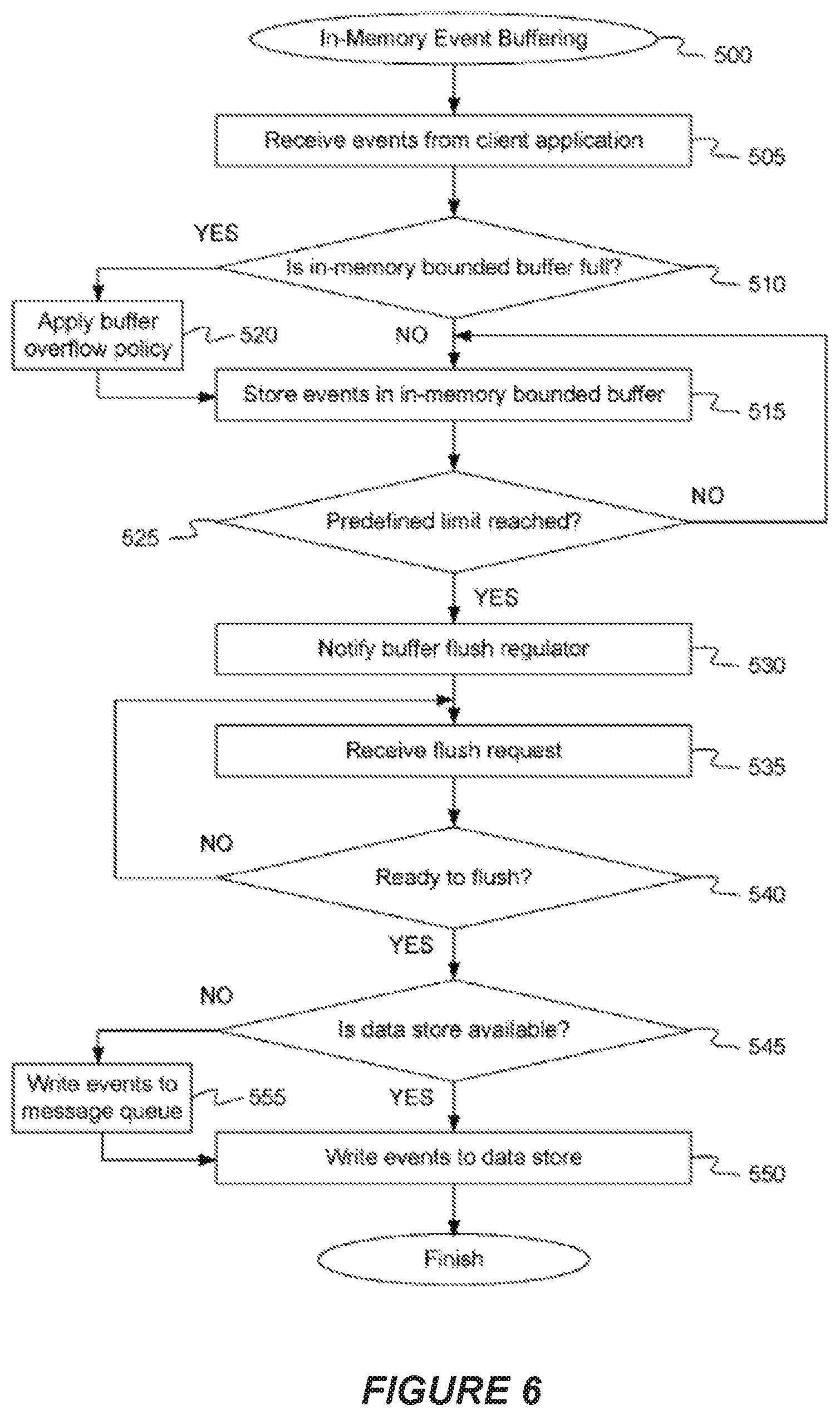
FIG. 6 is a flow diagram illustrating a method for in-memory buffering of event data, according to some implementations.
FIG. 7 is a flow diagram illustrating a method for in-memory buffering with plural buffer type assignment, according to some implementations.
FIG. 8 is a block diagram illustrating an in-memory buffer service with plural buffer type assignment, according to some implementations.
FIG. 9 is a block diagram illustrating a mapping that may be created in compile time, and used in runtime by an in-memory buffer service with plural buffer type assignment, according to some implementations.
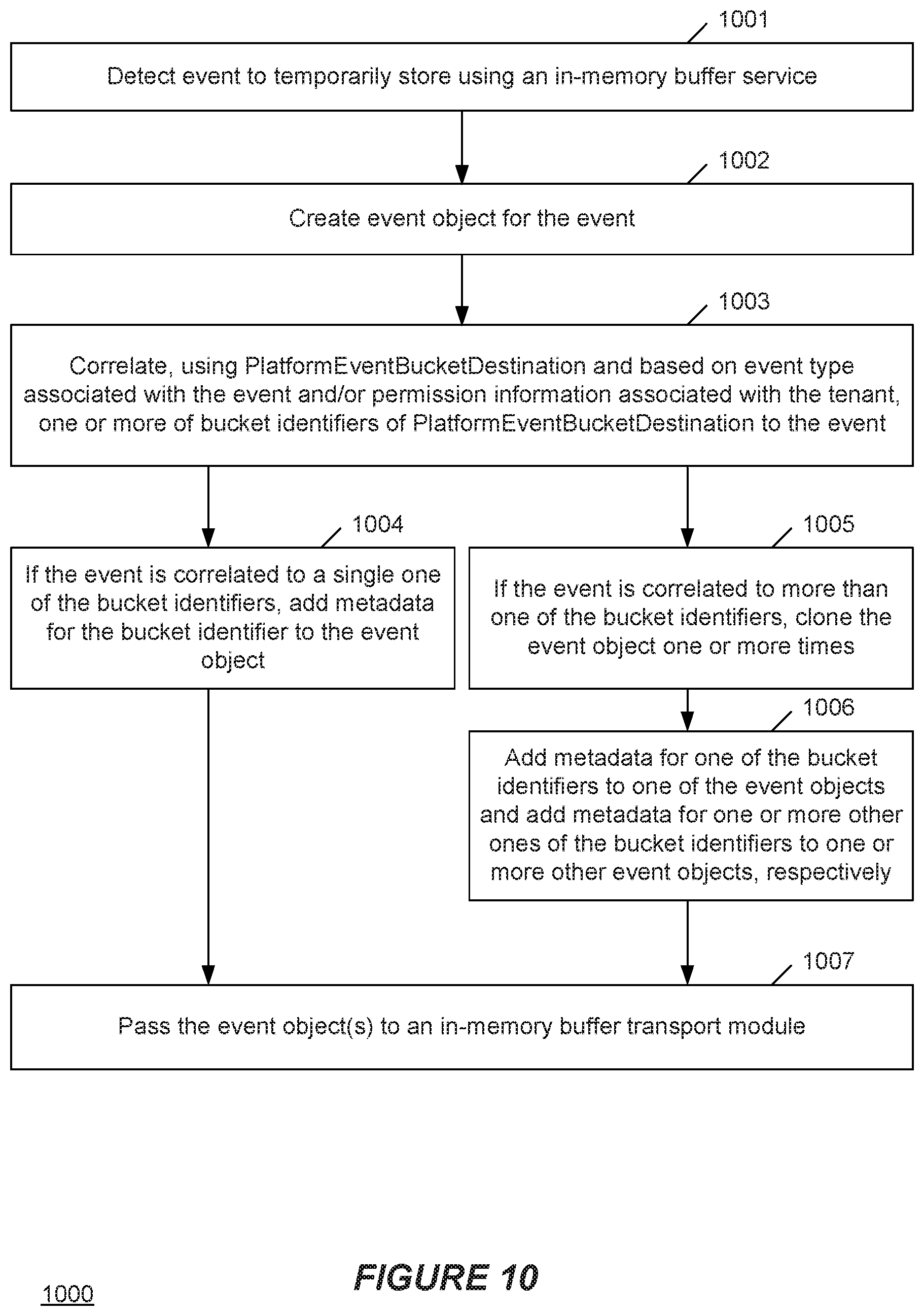
FIG. 10 is a flow diagram illustrating operations that may be performed by a processor to implement a correlation module in a multi-tenant embodiment, according to some implementations.
FIG. 11 is a flow diagram illustrating operations that may be performed by a processor to implement an in-memory buffer transport module in the multi-tenant embodiment of FIG. 10.
FIG. 12 is a flow diagram illustrating operations that may be performed by a processor to implement a consumer executor module in the multi-tenant embodiment of FIG. 10.
DETAILED DESCRIPTION
Examples of systems, apparatus, computer-readable storage media, and methods according to the disclosed implementations are described in this section. These examples are being provided solely to add context and aid in the understanding of the disclosed implementations. It will thus be apparent to one skilled in the art that the disclosed implementations may be practiced without some or all of the specific details provided. In other instances, certain process or method operations also referred to herein as "blocks," have not been described in detail in order to avoid unnecessarily obscuring the disclosed implementations. Other implementations and applications also are possible, and as such, the following examples should not be taken as definitive or limiting either in scope or setting.
In the following detailed description, references are made to the accompanying drawings, which form a part of the description and in which are shown, by way of illustration, specific implementations. Although these disclosed implementations are described in sufficient detail to enable one skilled in the art to practice the implementations, it is to be understood that these examples are not limiting, such that other implementations may be used and changes may be made to the disclosed implementations without departing from their spirit and scope. For example, the blocks of the methods shown and described herein are not necessarily performed in the order indicated in some other implementations. Additionally, in some other implementations, the disclosed methods may include more or fewer blocks than are described. As another example, some blocks described herein as separate blocks may be combined in some other implementations. Conversely, what may be described herein as a single block may be implemented in multiple blocks in some other implementations. Additionally, the conjunction "or" is intended herein in the inclusive sense where appropriate unless otherwise indicated; that is, the phrase "A, B or C" is intended to include the possibilities of "A," "B," "C," "A and B," "B and C," "A and C" and "A, B and C."
Some implementations described and referenced herein are directed to systems, apparatus, computer-implemented methods and computer-readable storage media for an in-memory service with plural buffer type assignment.
Some In-Memory Buffer Services (IMBSs) may include one or more buffers of a same buffer type. These IMBSs may allow only one-to-one relationship between event type and buffer type. However, the increasing demand in collecting events for various goals where some goals require processing and transporting an extremely large number of events with moderate to high tolerance of event loss whereas other goals require processing and transporting the same types of events but with zero to low tolerance to event loss. For example, a machine learning model may ingest information about events to train the model, which is an example of an application with a high tolerance of loss of events. However, conversely, audit and compliance is an example of an application with a low tolerance (e.g., no tolerance) of loss of events. Some embodiments described herein may use a first buffer type (with a first flush policy) for the events for the machine learning model and a second different buffer type (with a second flush policy) for events for audit and compliance.
Some embodiments disclosed herein may include an IMBS with plural buffer types, and to allow a one-to-many relationship between event type and buffer type. The IMBS may allow each event type to be specified to control which buffers(s) (e.g., bounded buffer(s)) the event is placed before events are flushed from the buffer to an appropriate one of consumer chains for processing an transporting to destination(s). The configuration and processing of one-to-many relationship between event type and buffer type may be referred to as "Plural Buffer Type Assignment."
A rate at which a consumer chain processes events from a buffer and the rate at which the events are placed into the buffer may impact buffer available capacity and thus event loss at a given point in time. Thus, when multiple events of the same event type are generated for different applications the delivery of events for one of the application may be impacted by the volume of events for the other application.
As an example of this impact, consider buffering for of different tenants of a multi-tenant database. If events generated by one or more organizations (e.g., tenants) and are placed into the same buffer where event A of event type M generated by organization X as part of a paid product requiring reliable and timely delivery and event B of the same event type M generated by organization Y as part of a free product and event C of the same event type M generated by organization Z as part of a pilot program generating large volume of event type M are all placed into the same buffer, the delivery of event A to its final destination(s) generated by organization X will be impacted by the volume of event B and event C and how fast event B and event C are retrieved from the buffer and processed. Using plural buffer type assignment, which may allow a one-to-many relationship between event type and buffer type, event type M may be configured to be placed into more than one buffer type based on the condition(s) set on the organization (tenant), allowing the same event type with multiple priorities and requirements to be transported and processed independently. With plural buffer type assignment, event type A can be configured to be placed into buffer type X when condition M is met and placed into buffer type Y when condition N is met. A same or different Consumer chain may be configured to process and transport events from buffer type X and buffer type Y. Condition M and condition N can be permissions set on customer's organization or other rules.
I. Example System Overview
FIG. 1A shows a block diagram of an example of an environment 10 in which an on-demand database service can be used in accordance with some implementations. The environment 10 includes user systems 12, a network 14, a database system 16 (also referred to herein as a "cloud-based system"), a processor system 17, an application platform 18, a network interface 20, tenant database 22 for storing tenant data 23, system database 24 for storing system data 25, program code 26 for implementing various functions of the system 16, and process space 28 for executing database system processes and tenant-specific processes, such as running applications as part of an application hosting service. In some other implementations, environment 10 may not have all of these components or systems, or may have other components or systems instead of, or in addition to, those listed above.
In some implementations, the environment 10 is an environment in which an on-demand database service exists. An on-demand database service, such as that which can be implemented using the system 16, is a service that is made available to users outside of the enterprise(s) that own, maintain or provide access to the system 16. As described above, such users generally do not need to be concerned with building or maintaining the system 16. Instead, resources provided by the system 16 may be available for such users' use when the users need services provided by the system 16; that is, on the demand of the users. Some on-demand database services can store information from one or more tenants into tables of a common database image to form a multi-tenant database system (MTS). The term "multi-tenant database system" can refer to those systems in which various elements of hardware and software of a database system may be shared by one or more customers or tenants. For example, a given application server may simultaneously process requests for a great number of customers, and a given database table may store rows of data such as feed items for a potentially much greater number of customers. A database image can include one or more database objects. A relational database management system (RDBMS) or the equivalent can execute storage and retrieval of information against the database object(s).
Application platform 18 can be a framework that allows the applications of system 16 to execute, such as the hardware or software infrastructure of the system 16. In some implementations, the application platform 18 enables the creation, management and execution of one or more applications developed by the provider of the on-demand database service, users accessing the on-demand database service via user systems 12, or third party application developers accessing the on-demand database service via user systems 12.
In some implementations, the system 16 implements a web-based customer relationship management (CRM) system. For example, in some such implementations, the system 16 includes application servers configured to implement and execute CRM software applications as well as provide related data, code, forms, renderable web pages and documents and other information to and from user systems 12 and to store to, and retrieve from, a database system related data, objects, and Web page content. In some MTS implementations, data for multiple tenants may be stored in the same physical database object in tenant database 22. In some such implementations, tenant data is arranged in the storage medium(s) of tenant database 22 so that data of one tenant is kept logically separate from that of other tenants so that one tenant does not have access to another tenant's data, unless such data is expressly shared. The system 16 also implements applications other than, or in addition to, a CRM application. For example, the system 16 can provide tenant access to multiple hosted (standard and custom) applications, including a CRM application. User (or third party developer) applications, which may or may not include CRM, may be supported by the application platform 18. The application platform 18 manages the creation and storage of the applications into one or more database objects and the execution of the applications in one or more virtual machines in the process space of the system 16.
According to some implementations, each system 16 is configured to provide web pages, forms, applications, data and media content to user (client) systems 12 to support the access by user systems 12 as tenants of system 16. As such, system 16 provides security mechanisms to keep each tenant's data separate unless the data is shared. If more than one MTS is used, they may be located in close proximity to one another (for example, in a server farm located in a single building or campus), or they may be distributed at locations remote from one another (for example, one or more servers located in city A and one or more servers located in city B). As used herein, each MTS could include one or more logically or physically connected servers distributed locally or across one or more geographic locations. Additionally, the term "server" is meant to refer to a computing device or system, including processing hardware and process space(s), an associated storage medium such as a memory device or database, and, in some instances, a database application (for example, OODBMS or RDBMS) as is well known in the art. It should also be understood that "server system" and "server" are often used interchangeably herein. Similarly, the database objects described herein can be implemented as part of a single database, a distributed database, a collection of distributed databases, a database with redundant online or offline backups or other redundancies, etc., and can include a distributed database or storage network and associated processing intelligence.
The network 14 can be or include any network or combination of networks of systems or devices that communicate with one another. For example, the network 14 can be or include any one or any combination of a LAN (local area network), WAN (wide area network), telephone network, wireless network, cellular network, point-to-point network, star network, token ring network, hub network, or other appropriate configuration. The network 14 can include a TCP/IP (Transfer Control Protocol and Internet Protocol) network, such as the global internetwork of networks often referred to as the "Internet" (with a capital "I"). The Internet will be used in many of the examples herein. However, it should be understood that the networks that the disclosed implementations can use are not so limited, although TCP/IP is a frequently implemented protocol.
The user systems 12 can communicate with system 16 using TCP/IP and, at a higher network level, other common Internet protocols to communicate, such as HTTP, FTP, AFS, WAP, etc. In an example where HTTP is used, each user system 12 can include an HTTP client commonly referred to as a "web browser" or simply a "browser" for sending and receiving HTTP signals to and from an HTTP server of the system 16. Such an HTTP server can be implemented as the sole network interface 20 between the system 16 and the network 14, but other techniques can be used in addition to or instead of these techniques. In some implementations, the network interface 20 between the system 16 and the network 14 includes load sharing functionality, such as round-robin HTTP request distributors to balance loads and distribute incoming HTTP requests evenly over a number of servers. In MTS implementations, each of the servers can have access to the MTS data; however, other alternative configurations may be used instead.
The user systems 12 can be implemented as any computing device(s) or other data processing apparatus or systems usable by users to access the database system 16. For example, any of user systems 12 can be a desktop computer, a work station, a laptop computer, a tablet computer, a handheld computing device, a mobile cellular phone (for example, a "smartphone"), or any other Wi-Fi-enabled device, wireless access protocol (WAP)-enabled device, or other computing device capable of interfacing directly or indirectly to the Internet or other network. The terms "user system" and "computing device" are used interchangeably herein with one another and with the term "computer." As described above, each user system 12 typically executes an HTTP client, for example, a web browsing (or simply "browsing") program, such as a web browser based on the WebKit platform, Microsoft's Internet Explorer browser, Apple's Safari, Google's Chrome, Opera's browser, or Mozilla's Firefox browser--or the like, allowing a user (for example, a subscriber of on-demand services provided by the system 16) of the user system 12 to access, process and view information, pages and applications available to it from the system 16 over the network 14.
Each user system 12 also typically includes one or more user input devices, such as a keyboard, a mouse, a trackball, a touch pad, a touch screen, a pen or stylus or the like, for interacting with a graphical user interface (GUI) provided by the browser on a display (for example, a monitor screen, liquid crystal display (LCD), light-emitting diode (LED) display, among other possibilities) of the user system 12 in conjunction with pages, forms, applications and other information provided by the system 16 or other systems or servers. For example, the user interface device can be used to access data and applications hosted by system 16, and to perform searches on stored data, and otherwise allow a user to interact with various GUI pages that may be presented to a user. As discussed above, implementations are suitable for use with the Internet, although other networks can be used instead of or in addition to the Internet, such as an intranet, an extranet, a virtual private network (VPN), a non-TCP/IP based network, any LAN or WAN or the like.
The users of user systems 12 may differ in their respective capacities, and the capacity of a particular user system 12 can be entirely determined by permissions (permission levels) for the current user of such user system. For example, where a salesperson is using a particular user system 12 to interact with the system 16, that user system can have the capacities allotted to the salesperson. However, while an administrator is using that user system 12 to interact with the system 16, that user system can have the capacities allotted to that administrator. Where a hierarchical role model is used, users at one permission level can have access to applications, data, and database information accessible by a lower permission level user, but may not have access to certain applications, database information, and data accessible by a user at a higher permission level. Thus, different users generally will have different capabilities with regard to accessing and modifying application and database information, depending on the users' respective security or permission levels (also referred to as "authorizations").
According to some implementations, each user system 12 and some or all of its components are operator-configurable using applications, such as a browser, including computer code executed using a central processing unit (CPU) such as an Intel Pentium.RTM. processor or the like. Similarly, the system 16 (and additional instances of an MTS, where more than one is present) and all of its components can be operator-configurable using application(s) including computer code to run using the processor system 17, which may be implemented to include a CPU, which may include an Intel Pentium.RTM. processor or the like, or multiple CPUs.
The system 16 includes tangible computer-readable media having non-transitory instructions stored thereon/in that are executable by or used to program a server or other computing system (or collection of such servers or computing systems) to perform some of the implementation of processes described herein. For example, computer program code 26 can implement instructions for operating and configuring the system 16 to intercommunicate and to process web pages, applications and other data and media content as described herein. In some implementations, the computer code 26 can be downloadable and stored on a hard disk, but the entire program code, or portions thereof, also can be stored in any other volatile or non-volatile memory medium or device as is well known, such as a ROM or RAM, or provided on any media capable of storing program code, such as any type of rotating media including floppy disks, optical discs, digital versatile disks (DVD), compact disks (CD), microdrives, and magneto-optical disks, and magnetic or optical cards, nanosystems (including molecular memory ICs), or any other type of computer-readable medium or device suitable for storing instructions or data. Additionally, the entire program code, or portions thereof, may be transmitted and downloaded from a software source over a transmission medium, for example, over the Internet, or from another server, as is well known, or transmitted over any other existing network connection as is well known (for example, extranet, VPN, LAN, etc.) using any communication medium and protocols (for example, TCP/IP, HTTP, HTTPS, Ethernet, etc.) as are well known. It will also be appreciated that computer code for the disclosed implementations can be realized in any programming language that can be executed on a server or other computing system such as, for example, C, C++, HTML, any other markup language, Java.TM., JavaScript, ActiveX, any other scripting language, such as VBScript, and many other programming languages as are well known may be used. (Java.TM. is a trademark of Sun Microsystems, Inc.).
FIG. 1B shows a block diagram of example implementations of elements of FIG. 1A and example interconnections between these elements according to some implementations. That is, FIG. 1B also illustrates environment 10, but FIG. 1B, various elements of the system 16 and various interconnections between such elements are shown with more specificity according to some more specific implementations. Additionally, in FIG. 1B, the user system 12 includes a processor system 12A, a memory system 12B, an input system 12C, and an output system 12D. The processor system 12A can include any suitable combination of one or more processors. The memory system 12B can include any suitable combination of one or more memory devices. The input system 12C can include any suitable combination of input devices, such as one or more touchscreen interfaces, keyboards, mice, trackballs, scanners, cameras, or interfaces to networks. The output system 12D can include any suitable combination of output devices, such as one or more display devices, printers, or interfaces to networks.
In FIG. 1B, the network interface 20 is implemented as a set of HTTP application servers 100.sub.1-100.sub.N. Each application server 100, also referred to herein as an "app server", is configured to communicate with tenant database 22 and the tenant data 23 therein, as well as system database 24 and the system data 25 therein, to serve requests received from the user systems 12. The tenant data 23 can be divided into individual tenant storage spaces 112, which can be physically or logically arranged or divided. Within each tenant storage space 112, user storage 114 and application metadata 116 can similarly be allocated for each user. For example, a copy of a user's most recently used (MRU) items can be stored to user storage 114. Similarly, a copy of MRU items for an entire organization that is a tenant can be stored to tenant storage space 112.
The process space 28 includes system process space 102, individual tenant process spaces 104 and a tenant management process space 110. The application platform 18 includes an application setup mechanism 38 that supports application developers' creation and management of applications. Such applications and others can be saved as metadata into tenant database 22 by save routines 36 for execution by subscribers as one or more tenant process spaces 104 managed by tenant management process 110, for example. Invocations to such applications can be coded using PL/SOQL 34, which provides a programming language style interface extension to API 32. A detailed description of some PL/SOQL language implementations is discussed in commonly assigned U.S. Pat. No. 7,730,478, titled METHOD AND SYSTEM FOR ALLOWING ACCESS TO DEVELOPED APPLICATIONS VIA A MULTI-TENANT ON-DEMAND DATABASE SERVICE, by Craig Weissman, issued on Jun. 1, 2010, and hereby incorporated by reference in its entirety and for all purposes. Invocations to applications can be detected by one or more system processes, which manage retrieving application metadata 116 for the subscriber making the invocation and executing the metadata as an application in a virtual machine.
The system 16 of FIG. 1B also includes a user interface (UI) 30 and an application programming interface (API) 32 to system 16 resident processes to users or developers at user systems 12. In some other implementations, the environment 10 may not have the same elements as those listed above or may have other elements instead of, or in addition to, those listed above.
Each application server 100 can be communicably coupled with tenant database 22 and system database 24, for example, having access to tenant data 23 and system data 25, respectively, via a different network connection. For example, one application server 100.sub.1 can be coupled via the network 14 (for example, the Internet), another application server 100.sub.N-1 can be coupled via a direct network link, and another application server 100.sub.N can be coupled by yet a different network connection. Transfer Control Protocol and Internet Protocol (TCP/IP) are examples of typical protocols that can be used for communicating between application servers 100 and the system 16. However, it will be apparent to one skilled in the art that other transport protocols can be used to optimize the system 16 depending on the network interconnections used.
In some implementations, each application server 100 is configured to handle requests for any user associated with any organization that is a tenant of the system 16. Because it can be desirable to be able to add and remove application servers 100 from the server pool at any time and for various reasons, in some implementations there is no server affinity for a user or organization to a specific application server 100. In some such implementations, an interface system implementing a load balancing function (for example, an F5 Big-IP load balancer) is communicably coupled between the application servers 100 and the user systems 12 to distribute requests to the application servers 100. In one implementation, the load balancer uses a least-connections algorithm to route user requests to the application servers 100. Other examples of load balancing algorithms, such as round robin and observed-response-time, also can be used. For example, in some instances, three consecutive requests from the same user could hit three different application servers 100, and three requests from different users could hit the same application server 100. In this manner, by way of example, system 16 can be a multi-tenant system in which system 16 handles storage of, and access to, different objects, data and applications across disparate users and organizations.
In one example storage use case, one tenant can be a company that employs a sales force where each salesperson uses system 16 to manage aspects of their sales. A user can maintain contact data, leads data, customer follow-up data, performance data, goals and progress data, etc., all applicable to that user's personal sales process (for example, in tenant database 22). In an example of a MTS arrangement, because all of the data and the applications to access, view, modify, report, transmit, calculate, etc., can be maintained and accessed by a user system 12 having little more than network access, the user can manage his or her sales efforts and cycles from any of many different user systems. For example, when a salesperson is visiting a customer and the customer has Internet access in their lobby, the salesperson can obtain critical updates regarding that customer while waiting for the customer to arrive in the lobby.
While each user's data can be stored separately from other users' data regardless of the employers of each user, some data can be organization-wide data shared or accessible by several users or all of the users for a given organization that is a tenant. Thus, there can be some data structures managed by system 16 that are allocated at the tenant level while other data structures can be managed at the user level. Because an MTS can support multiple tenants including possible competitors, the MTS can have security protocols that keep data, applications, and application use separate. Also, because many tenants may opt for access to an MTS rather than maintain their own system, redundancy, up-time, and backup are additional functions that can be implemented in the MTS. In addition to user-specific data and tenant-specific data, the system 16 also can maintain system level data usable by multiple tenants or other data. Such system level data can include industry reports, news, postings, and the like that are sharable among tenants.
In some implementations, the user systems 12 (which also can be client systems) communicate with the application servers 100 to request and update system-level and tenant-level data from the system 16. Such requests and updates can involve sending one or more queries to tenant database 22 or system database 24. The system 16 (for example, an application server 100 in the system 16) can automatically generate one or more SQL statements (for example, one or more SQL queries) designed to access the desired information. System database 24 can generate query plans to access the requested data from the database. The term "query plan" generally refers to one or more operations used to access information in a database system.
Each database can generally be viewed as a collection of objects, such as a set of logical tables, containing data fitted into predefined or customizable categories. A "table" is one representation of a data object, and may be used herein to simplify the conceptual description of objects and custom objects according to some implementations. It should be understood that "table" and "object" may be used interchangeably herein. Each table generally contains one or more data categories logically arranged as columns or fields in a viewable schema. Each row or element of a table can contain an instance of data for each category defined by the fields. For example, a CRM database can include a table that describes a customer with fields for basic contact information such as name, address, phone number, fax number, etc. Another table can describe a purchase order, including fields for information such as customer, product, sale price, date, etc. In some MTS implementations, standard entity tables can be provided for use by all tenants. For CRM database applications, such standard entities can include tables for case, account, contact, lead, and opportunity data objects, each containing pre-defined fields. As used herein, the term "entity" also may be used interchangeably with "object" and "table."
In some MTS implementations, tenants are allowed to create and store custom objects, or may be allowed to customize standard entities or objects, for example by creating custom fields for standard objects, including custom index fields. Commonly assigned U.S. Pat. No. 7,779,039, titled CUSTOM ENTITIES AND FIELDS IN A MULTI-TENANT DATABASE SYSTEM, by Weissman et al., issued on Aug. 17, 2010, and hereby incorporated by reference in its entirety and for all purposes, teaches systems and methods for creating custom objects as well as customizing standard objects in a multi-tenant database system. In some implementations, for example, all custom entity data rows are stored in a single multi-tenant physical table, which may contain multiple logical tables per organization. It is transparent to customers that their multiple "tables" are in fact stored in one large table or that their data may be stored in the same table as the data of other customers.
II. In-Memory Buffer Service
Embodiments are described for an in-memory buffer service. In certain high volume event systems, it may be beneficial to ingest and process events as quickly and efficient as possible (i.e., in real-time). Depending on the implementation, this may include ingesting, processing, and persisting potentially millions of events over the span of an hour or billions of events over the span of a week. For instance, a certain system may store up to a week's worth of details from sets of operations that are executed as a single unit (e.g., "Apex transactions") in an open source, non-relational, distributed database such as Apache HBase.TM., or other data store. This may be accomplished by pointing a debug log event handler that supplies limit usage information, or any other program or component that generates a high volume of events or other data elements to the data store. In other embodiments, some other data store may be used, such as a NoSQL database, a non-opensource database, a relational database, a non-distributed database, or other type of data store.
In an implementation that averages 7.3 billion Apex executions per month (or 243 million per day) being stored in the data store, storing one row per transaction limit with 8 types of limits would require storing 58.4 billion rows per month or about 1.8 billion rows per day across an entire service. Thus, if only raw event data were kept around for a week, that would require 13.1 billion rows at a time before being deleted. In other implementations, there may be up to 15 types of limits, which would result in even more rows being stored. This high volume situation could benefit significantly from a new way for handling event data at scale with high throughput.
In one embodiment, an in-memory buffer service running on a multi-tenant application server provides a low latency application program interface (API) that writes objects, such as event records, to the data store. In other embodiments, the application server may not server multiple clients, but rather is utilized by a single client that generates significant a volume of event data. The in-memory buffer service provides a "store and forward" based service for data objects, where those objects (e.g., events) are temporarily stored in an in-memory bounded buffer before being forward to a data store for longer term storage. A capture service can store events in a bounded buffer, where they may be kept in memory until the number of objects reaches a predefined limit, or the events have been in memory for a predetermined period of time (e.g., 5 seconds, 10 seconds, 30 seconds, 1 minute, etc.). The in-memory buffer provides a very low latency API to write objects and can be done very quickly. For instance, in some examples, writing the bounded buffer can be done in as little as 0.08 microseconds.
The in-memory buffer may be responsible for supporting a concurrently writable API, which enables the storing of events in memory and manages flushing of the buffer. In some embodiments, the in-memory buffer may include a plurality of buffer segments, where each segment is single threaded. Each segment can support high read consistency by waiting until all (or most) write threads are complete before read threads are initiated. Thus, each segment may only be read once. Additionally, the concurrent bounded buffer, comprised of segments, may be used to store events concurrently from various threads. The bounded buffer may also maintain a notion of load factor and may support two types of overflow policies. For example a buffer flush may be initiated when the buffer load reaches some predefined limit (e.g., 80% capacity). In some embodiments, the bounded buffer keeps the latest object by replacing an oldest object with a recent object (i.e., first in first out). In another embodiment, the bounded buffer drops the latest object if the buffer is full. A buffer flush regulator may further be used to regulate the flushing of the buffer. The regulating may be based on size and time, which will queue up the event for consumption and writing to the data store. For example the concurrent bounded buffer may provide a notification when the number of objects reaches a predefined limit that triggers buffer flushing.
Additionally, a consumer executor service is responsible for consuming the in-memory buffer and uses a dynamically sized thread pool to consume (i.e., process) the objects in parallel fashion in order to maximize throughput. The consumer executor service may include a service thread that initiates automatic restarts if a main thread is interrupted. The extension may also include an asynchronous API for starting and stopping a thread. The service thread further may use, in one implementation, Java's ThreadPool to get worker to run the consumer tasks concurrently and in a reliable manner. The service thread also may iteratively call blockedGetAndReset( ) API of the buffer and may assign a set of data to the consumer task. The consumer task may be eventually run by the ThreadPool's worker thread.
A consumer factory of the consumer executor service allows a user to customize a consumer task. A consumer task may first try to write to the data store (e.g., HBase.TM., Bigtable.TM., MongoDB.TM., etc.) directly in a given time in order to reduce the load on a message queue (MQ) and to make data available instantaneously. If writing to the data store fails, however, the consumer task may enqueue objects in the MQ, which eventually writes the objects to the data store via an MQ Handler. In some embodiments, a shutdown hook is used to close the service properly when a shutdown of the application server is requested. A log of statistics may also be kept, and the consumer executor service may be restarted if it was terminated for unknown reasons.
FIG. 1 is a block diagram illustrating a computing environment with an in-memory buffer service, according to an embodiment. In one embodiment, network environment 100 includes application server 110, client devices 120, 122, 124 and data store 130. Application server 110 and client devices 120, 122, 124 may be connected through a series of one or more networks 140, which may be, for example, a local area network (LAN), a wide area network (WAN), a global area network (GAN) such as the Internet, or a combination of such networks. In another embodiment, application server 110 and client devices 120, 122, 124 may have a direct connection to each of the other devices in the network. The illustrated embodiment shows one application server 110, and three client devices 120, 122, 124; however, in other embodiments, there may be any number of servers or client devices, and environment 100 may include additional and/or different components
Each of client devices 120, 122, 124 may be, for example, a personal computer (PC), workstation, laptop computer, tablet computer, mobile phone, smartphone, personal digital assistant (PDA) or the like. Client devices 120, 122, 124 may communicate with application server 110 to access resources on application server, such as client application 112. For example a user may access client application 112 through a web browser or other HTTP client application on the client device.
In one embodiment, application server 110 may be any computing device, such as computing system 800, described below with respect to FIG. 8. In one embodiment, application server 110 may be a multi-tenant application server designed to provide access to a number of client applications, such as client application 112, to one more client devices, such as client devices 120, 122, 124. In another embodiment, application server 110 may be a single-tenant application server design to service a single client. Client application 112 and other resources provided by application server 110, such as processing resources, storage resources, etc., may be maintained by application server 110 and made available to the users of client devices 120, 122, 124 as needed (i.e., "on-demand"). This application server 110 can include various elements of hardware and software of a database system may be shared by one or more customers or tenants. For example, application server 110 may simultaneously process requests for a great number of customers. Application server 110 may include an application platform including a framework that allows the applications to execute, such as the hardware or software infrastructure of the system. In one embodiment, the application platform enables the creation, management and execution of one or more applications, such as client application 122, developed by the provider of the application server, customers accessing the application server 110 via client devices 120, 122, 124, or third party application developers.
In one embodiment, application server 110 includes in-memory buffer service 114. In-memory buffer service 114 can ingest and process events generated by client application 112, buffer those events and eventually store the events in data store 130. In one embodiment, data store 130 provides an application programming interface (API) which can be called by the in-memory buffer service 114 in order to store the events in data store 130. In one embodiment, data store 130 may be an open source, non-relational, distributed database such as Apache HBase.TM., Bigtable.TM., MongoDB.TM., or other data store. Examples of events generated by client application 112 may include errors, exceptions, faults, failures, crashes, incidents, or other occurrences. For example, client application 112 may include a user interface layer that presents a user interface visible on one of client devices 120, 122, 124. Through selection of a user interface element, the user may initiate some processing operation in a logical layer of the client application that hits some hard limit defined by the application server 110 (e.g., number of processing cycles consumed per day, amount of storage resources consumed) and page rendering is stopped. The reaching of this hard limit may trigger the creation of an event by client application 112 which is recorded for possible future review. The volume at which such events are potentially generated and conventional means for recording and storing these events may result in an unacceptable level of latency. As such, in one embodiment, in-memory buffer service 114 can ingest and process the events, buffer the events and eventually store the events in data store 130. The buffering of the events in memory before storage in data store 130 can allow a high volume of events to be processed in near real-time with minimal latency and without adversely affecting performance of the application server 110 or client application 112. Additional details of the in-memory buffer service 114 are provided below.
FIG. 2 is a block diagram illustrating an application server with an in-memory buffer service, according to an embodiment. As described above, application server 110 may include client application 112, in-memory buffer service 114 and data store 130. In one embodiment, data store 130 may be internal to application server 110. In another embodiment, data store 130 may be external to application server 110 and may be connected to application server 110 over a network or other connection. In other embodiments, application server 110 may include different and/or additional components which are not shown in order to simplify the description. In one embodiment, data store 130 may be embodied by one or more mass storage devices which can include, for example, flash memory, magnetic or optical disks, or tape drives; read-only memory (ROM); random-access memory (RAM); erasable programmable memory (e.g., EPROM and EEPROM); flash memory; or any other type of storage medium.
Client application 112 may be any type of computer application program that generates events. For example, client application 112 may be an entertainment application, productivity application, business application, social networking application or other types of application. In one embodiment, in-memory buffer 114 processes events for storage in data store 130. In other embodiments, in-memory buffer 114 may process any other type of data object for storage in data store 130 or elsewhere. In one embodiment, a capture service 202 running on application server 110 receives events from client application 112 that are to be stored in data store 130. Capture service 202 temporarily stores the received events in bounded buffer 204. The bounded buffer 204 may include a plurality of single-threaded segments, to which the capture service 202 can write the events in parallel. In one embodiment, bounded buffer 204 may include 16 single-threaded segments, each of which can be written in parallel with a different event generated by client application 112. The size of bounded buffer 204 is configurable according to the particular implementation. In one embodiment, the buffer size may be approximately 10 megabytes (MB) to 20 MB. In other embodiments, the buffer may have a different size, such as 1 MB, 50-100 MB, 1 terabyte (TB), etc.).
In one embodiment, in-memory buffer service 114 further includes a buffer flush regulator 206. Buffer flush regulator 206 controls when bounded buffer 204 is emptied (i.e., "flushed") for consumption by consumer executor service 208 and storage in data store 130. In one embodiment, logic associated with bounded buffer 204 monitors the load on bounded buffer 204 and provides a notification to the buffer flush regulator 206 when the number of events stored in the bounded buffer 204 reaches a predefined limit (e.g., 80% full) or when a predefined amount of time has passed since a contents of the bounded buffer 204 was written to data store 130 (e.g., 10 seconds). In one embodiment, consumer executor service 208 periodically sends a request for buffer flushing to buffer flush regulator 206. Buffer flush regulator 206 determines whether a notification has been received from bounded buffer 204 indicating that either the predefined size limit or the predefined time limit has been reached. If not, buffer flush regulator 206 denies the request. If the notification has been received, buffer flush regulator 206 grants the request and consumer executor service 208 may consume the events in the bounded buffer 204 using a dynamically sized thread pool of consumer threads to read the segments of the bounded buffer 204 in parallel. By consuming the events, consumer executor service 208 reads the events from bounded buffer 204 and writes the events to data store 130.
In some situations, all of the segments of bounded buffer 204 may be filled with events and new events are received by capture service 202 before buffer flush regulator 206 can empty the contents of bounded buffer 204. Bounded buffer 204 may handle this situation in a number of different ways according to a defined overflow policy. In one embodiment, bounded buffer 204 may implement a "keep latest" overflow policy where the oldest event in bounded buffer 204 is overwritten with the newly received event from client application 112. In another embodiment, bounded buffer 204 may implement a "drop latest" overflow policy, where the newly received event is prevented from being stored in bounded buffer 204.
FIG. 3 is a block diagram illustrating an application server with an in-memory buffer service, according to an embodiment. In one embodiment, application server 110 includes in-memory buffer service 114 and consumer executor service 208. In one embodiment, consumer executor service 208 may be part of in-memory buffer service 114; however, in another embodiment, consumer executor service 208 may be a separate, standalone, service. In one embodiment, an in-memory bounded buffer utilized by the in-memory buffer service 114 includes a plurality of single-threaded segments 302, to which capture service 202 can write the events in parallel. In one embodiment, the bounded buffer may include 16 single-threaded segments 302, each of which can be written in parallel with a different event or other data object. In other embodiments, the bounded buffer may have some other number of segments, including more or less than 16 segments.
In one embodiment, in-memory buffer service 114 further includes buffer flush regulator 206. Buffer flush regulator 206 controls when bounded buffer 204 is emptied (i.e., "flushed") for consumption by consumer executor service 208 and storage in data store 130. In one embodiment, in-memory buffer service 114 monitors the load on the buffer segments 302 and provides a notification to the buffer flush regulator 206 when a certain portion or percentage of the buffer segments 302 are full (e.g., 80% full) or when a predefined amount of time has passed since a contents of the buffer segments 302 were flushed (e.g., 10 seconds). In one embodiment, a main service thread 304 in consumer executor service 208 may periodically send a request for buffer flushing to buffer flush regulator 206. Buffer flush regulator 206 may determine whether a notification has been received from bounded buffer 204 indicating that either the predefined size limit or the predefined time limit have been reached. If not, buffer flush regulator 206 denies the request. If the notification has been received, buffer flush regulator 206 grants the request and consumer executor service 208 may consume the events in the bounded buffer 204 using a dynamically sized thread pool 306 of consumer threads 308 to read the segments of the bounded buffer 204 in parallel. Dynamically sized thread pool 306 can add or remove consumer threads 308 so that the number of consumer threads 308 matches the number of buffer segments 302 being consumed. For example, if all 16 segments 302 are being read, dynamically sized thread pool 306 can have 16 consumer threads 308. If, however, only 10 buffer segments 302 contain events, then thread pool 306 need only include 10 threads 308. The consumer threads 308 read the events from buffer segments 302 in parallel and write the events to data store 130.
FIG. 4 is a block diagram illustrating an application server with dual in-memory bounded buffers, according to an embodiment. In one embodiment, application server 110 includes in-memory buffer service 114 and consumer executor service 208. In one embodiment, in-memory buffer service 114 utilizes two or more bounded buffers 204, 404 to buffer events received from a client application. In one embodiment, each bounded buffer 204, 404 may include a plurality of single-threaded segments, each of which can be written in parallel with a different event or other data object. The dual bounded buffers 204, 404 can be used alternately to prevent a service interruption. For example, once bounded buffer 204 has been filled with event data and is in the process of being flushed by consumer executor service 208, additional events may be received from the client application or other source. Since bounded buffer 204 is not available, those new events cannot be stored in bounded buffer 204. Instead, bounded buffer 404 may be utilized to store the newly received events. Bounded buffer 404 can function as the current buffer, storing new events until it is ready to be flushed. Buffer flush regulator 206 can initiate a flush of bounded buffer 404 using the same conditions described above with respect to bounded buffer 204. Once bounded buffer 404 is flushed, in-memory buffer service 114 can return to using bounded buffer 204 as the current buffer. The process can repeat, alternating between the available buffers to prevent service interruption and the loss of any event data. In other embodiments, there may be more than two bounded buffers which are cycled through in a similar fashion. For example, a given server, may have three, four, or more buffers available. In one embodiment, a server may initially have some number of buffers (e.g., two), but additional buffers may be allocated as the need arises. Thus, if event data is being received at a rate that cannot be serviced using the current number of buffers, the in-memory buffer service or other logic may allocate additional buffers in order to accommodate the higher volume of events.
Under normal operation the threads of the dynamically sized thread pool 306 in consumer executor service 208 may write the events read from either bounded buffer 204 or bounded buffer 404 directly to data store 130. Depending on the implementation, however, the data store 130 may be a distributed system and possibly take a significant period of time to be written. In such a case, or if all or a portion of the data store 130 is temporarily unavailable, consumer executor service 208 may enqueue the events from the bounded buffer 204 or 404 in a message queue 406 for subsequent writing to data store 130 after data store 130 becomes available. In one embodiment, consumer executor service 208 may first try to write directly to data store 130, but if data store 130 does not respond within some period of time, message queue 406 may be utilized. Message queue 406 may be any available in-memory or out-of-memory data structure that can temporarily accommodate the events before they are stored in data store 130. In one embodiment, message queue 406 may be large enough to store the contents of one bounded buffer 204 at a time. In another embodiment, message queue 406 may be large enough to store the contents of multiple buffers concurrently.
FIG. 5 is a flow diagram illustrating a method for in-memory buffering of event data, according to an embodiment. The method 500 may be performed by processing logic that comprises hardware (e.g., circuitry, dedicated logic, programmable logic, microcode, etc.), software (e.g., instructions run on a processor to perform hardware simulation), firmware, or a combination thereof. The processing logic is configured to receive event data for storage in a data store and buffer the event data in an in-memory bounded buffer prior to storage in the data store. In one embodiment, method 500 may be performed by in-memory buffer service, as shown in FIGS. 1-4.
Referring to FIG. 5, at block 505, method 500 receives events from client application 112. In one embodiment, a capture service 202 running on application server 110 receives events from client application 112 that are to be stored in data store 130. In another embodiment, capture service 202 may receive generic data objects from some other source for in-memory buffering.
At block 510, method 500 determines whether in-memory bounded buffer 204 is full. In one embodiment, bounded buffer 204 may include 16 single-threaded segments, each of which can be written in parallel with a different event generated by client application 112. In one embodiment, in-memory buffer service 114 determines whether each of the buffer segments has been written with an event. If each segment contains an event, then in-memory buffer service 114 determines that the bounded buffer 204 is full. If there are one or more segments of the bounded buffer 204 that do not contain events, then in-memory buffer service 114 determines that the bounded buffer 204 is not full.
If in-memory bounded buffer 204 is not full, at block 515, method 500 stores the received events in the in-memory bounded buffer 204. In one embodiment, capture service 202 writes the received events to one or more of the segments 302 of in-memory bounded buffer 204 in parallel.
If in-memory bounded buffer 204 is full, at block 520, method 500 applies a buffer overflow policy prior to storing the events. In one embodiment, bounded buffer 204 may implement a "keep latest" overflow policy where the oldest event in bounded buffer 204 is overwritten with the newly received event from client application 112. In another embodiment, bounded buffer 204 may implement a "drop latest" overflow policy, where the newly received event is prevented from being stored in bounded buffer 204.
At block 525, method 500 determines if a predefined limit has been reached. In one embodiment, in-memory buffer service 114 monitors the load on bounded buffer 204 and determines when the number of events stored in the bounded buffer 204 reaches a predefined limit (e.g., 80% full) or when a predefined amount of time has passed since a contents of the bounded buffer 204 was written to data store 130 (e.g., 10 seconds). If the predefined limit has been reached, at block 530, method 500 provides a notification to buffer flush regulator 206. In one embodiment, in-memory buffer service 114 provides the notification to buffer flush regulator 206.
At block 535, method 500 receives a buffer flush request from consumer executor service 208. In one embodiment, consumer executor service 208 may periodically send a request for buffer flushing to buffer flush regulator 206. The period with which the request is sent can be configurable depending on the particular implementation.
At block 540, method 500 determines whether the in-memory bounded buffer 204 is ready to be flushed. Buffer flush regulator 206 may determine whether a notification has been received from bounded buffer 204, at block 530, indicating that either the predefined size limit or the predefined time limit have been reached. If not, buffer flush regulator 206 denies the request.
If the in-memory bounded buffer 204 is ready to be flushed, at block 545, method 500 determines whether the data store 130 is available. Depending on the implementation, the data store 130 may be a distributed system and possibly take a significant period of time to be written. In such a case, all or a portion of the data store 130 may be temporarily unavailable.
If the data store 130 is available, at block 550, method 500 consumes the events from the in-memory bounded buffer 204 by writing the events directly to the data store 130. In one embodiment, consumer executor service 208 may consume the events in the bounded buffer 204 using a dynamically sized thread pool of consumer threads to read the segments of the bounded buffer 204 in parallel. By consuming the events, consumer executor service 208 reads the events from bounded buffer 204 and writes the events to data store 130.
If the data store is not available, at block 555, method 500 enqueues the events from in-memory bounded buffer 204 in a message queue 406 for subsequent writing to the data store 130 after the data store 130 becomes available. Message queue 406 may be any available in-memory or out-of-memory data structure that can temporarily accommodate the events before they are stored in data store 130. In one embodiment, message queue 406 may be large enough to store the contents of one bounded buffer 204 at a time. In another embodiment, message queue 406 may be large enough to store the contents of multiple buffers concurrently. A detailed description of some in-memory buffer service implementations is discussed in commonly assigned U.S. Pat. No. 9,767,022, titled IN-MEMORY BUFFER SERVICE, first named inventor Aakash Pradeep, issued on Sep. 19, 2017, and hereby incorporated by reference in its entirety and for all purposes.
III. In-Memory Buffer Service with Plural Buffer Type Assignment
Any application server described herein may include a processor to operate any IMBS described herein and to further perform plural buffer type assignment for events (e.g., login events, API events, report events, or the like, or combinations thereof), which may allow a one-to-many relationship mapping between event type and buffer type in the IMBS. Plural buffer type assignment may control and manage event placement into appropriate buffer(s) (e.g., any buffer described here, such as bounded buffer(s)) and passes event to appropriate consumer chain to process and transport event.
FIG. 7 is a flow diagram illustrating a method 700 for in-memory buffering with plural buffer type assignment, according to some implementations. The method 700 may be performed by any application servers described herein (e.g., by one or more application servers). For instance, the method 700 may be performed by application server 110 (FIG. 2). The method 700 may be performed by an in-memory buffer similar to in-memory buffer 114, e.g., by a processor (e.g., one or more processors) of the application server 100. The processor may be a general purpose processor to execute instructions that transform it into a special purpose processor.
In block 701, the processor may detect data to temporarily store in a group of buffers (e.g., a group of bounded buffers) using an IMBS. In some embodiments, the group of buffers may be similar to any group of buffers described herein, and may include more than one buffer type. In some embodiments, the detected data may include an event similar to any event described herein (e.g., created by a client application similar to client application 112 of FIG. 2). The processor may create a data object for the detected data (not shown, e.g., an event object for an event).
In block 702, the processor may correlate, to the detected data, one or more identifiers of a set of identifiers. The set of identifiers may include a first identifier corresponding to a first buffer type of the group of buffers and one or more second different identifiers corresponding to one or more second different buffer types, respectively, of the group of buffers. One or more buffer flush regulators similar to buffer flush regulator 206 (FIG. 3) may flush the different buffers according to different respective sets of flush policies. In one example, the set of identifiers may include three identifiers, e.g., a first identifier for a first buffer type associated with a first flush interval and/or threshold, a second identifier for a second buffer type that is different than the first buffer type and associated with a second different flush interval and/or threshold, and a third identifier for a third buffer type that is different than the second buffer type and associated with a third different flush interval and/or threshold. The in-memory buffer may create any number of buffers for each buffer type (e.g., each buffer type may include a single buffer or two or more buffers similar to bounded buffers 204 and 404 of FIG. 5).
If the detected data is correlated to only a single identifier of the set of identifiers in diamond 703, then in block 704 the processor may store the corresponding identifier in a first data object (e.g., the created data object) for the detected data to control placement of the first data object in one of the buffers of the corresponding buffer type.
If the detected data is correlated to more than one identifier of the set of identifiers in diamond 703, then in block 705 the processor may store a different one of the more than one identifiers in each one of second data objects for the detected data to control placement of the second data objects in ones of the buffers of the corresponding buffer types, respectively. In some examples, the processor may create a set of identical data objects following detection of the data (e.g., identical event objects for an event) to provide the second data objects prior to storing the identifiers. In some examples, the processor may create the set of identical data objects to provide the second data objects by cloning the created data object one or more times in response to correlating the detected data to more than one of the identifiers.
In block 706, the processor may identify one of the data objects and use the stored identifier of the identified data object to place the identified data object in one of the buffers of the group of buffers. In some embodiments, for scaling or other reasons, the processor of the application server (e.g., one or more processors of one or more application servers) may include plural subcomponents (such as plural cores/processors to operate different threads or software contexts), and the identification in block 706 may be performed by a different subcomponent than a subcomponent that performed one or more of the other blocks of FIG. 7.
FIG. 8 is a block diagram illustrating an in-memory buffer service 800 with plural buffer type assignment, according to some implementations. The in-memory buffer service 800 may be similar to any in-memory buffer service described herein, and also may include a mapping 801 (e.g., PlatformEventBucketDestination Mapping Metadata), a module 802 (e.g., BufferProviderService), a module 803 (e.g., ObjectCreation), a module 804 (e.g., InMemoryBufferTransport), a module 805 (e.g., ConsumerChainProviderService), and a module 806 (e.g., a ConsumerExecutorService).
At compile time, the in-memory buffer service 800 may create one-to-many relationship mapping 801 between fields such as event, identifier (e.g., bucket), and condition (e.g., permission in multi-tenant embodiments). Each of the entries 899 of the mapping 801 may be a unique combination of values for these fields. Identifier may be defined by buffer type and consumer chain type, in some embodiments. Condition may be permissions (e.g., in multi-tenant embodiments) or other rules. An event type may be associated with one or more identifier, and an identifier for a given event may be associated with one or more condition.
More than one condition set can be used to control the relationship between event type and identifier. FIG. 9 illustrates example values to illustrate in a multi-tenant embodiment. In this case, a login event mapped to bucket A may be controlled by permissions W and X. In such a case, the tenant having either permissions W or permissions X enabled may have login event stored in buffer type A and processed by consumer chain type A.
Referring again to FIG. 8, at run time (e.g., event capture time), the module 803 may detect an event. The module 803 may determine, by consulting the mapping using the event type 832 associated with the event and condition information 830, whether to capture the event and, if so, may correlate one or more of the identifier values 831 to the event.
In the case in which the one or more identifier values 831 is a single identifier value 831, the module 803 may capture the event and create an event object. The module 803 may store the single identifier value 831 as metadata in the event object.
In the case in which the one or more identifier values 831 includes more than one identifier values 831, say N identifier values 831, the module 803 may clone the event object N-1 times. The module 803 may store each identifier value 831 in a different one of the event objects.
Module 804 may identify an event object and determine the buffer type 839 the event object is to be placed by consulting module 802. Module 804 may provide the event type 832 and the identifier value 831 to the module 802, and module 802 may provide the buffer type 839. Module 804 may place the event object into an appropriate buffer based on the buffer type 839.
When an event object in one of the buffers is to be flushed from the buffer to a consumer chain, the module 806 may determine a consumer chain type 849 to process the event object by consulting module 805. The module 806 may read the identifier value 831, and may provide the event type 832 and the identifier value 831 of the event object to the module 805. The module 805 may provide the consumer chain type 849 to the module 806. The module 806 may pass the event object from the buffer to an appropriate consumer chain based on the consumer chain type 849 and/or perform any other operation described with respect to the consumer executor service 208 of FIG. 5. The consumer chain may be responsible to invoke an appropriate transport destination.
In some embodiments, for scaling or other purposes, operations performed following placement into the buffer (e.g., flushing to a consumer chain) may be performed by a different thread than a thread used to place the event object into the buffer. For example, the module 806 may be similar in any respect to the module to consumer executor service 208 of FIG. 5, e.g., module 806 may consume event objects in a buffer using a dynamically sized thread pool of consumer threads to read the segments of the buffer in parallel. By consuming the events objects, the module 806 may read the event objects from the buffer, and may write information from the event objects (e.g., the payload) to a data store similar to data store 130 (FIG. 5).
Some embodiments may support multi-tenant environments to allow the same event type generated on the same or different tenants to be stored in multiple buffer types based on the condition(s) which can be permission(s) or other rule(s) set on the tenant. Multiple tenants may use the same buffer to store events, and the events may be transported to same or different set of destinations. In these embodiments, each tenant may have full control of what buffer types and what set of destinations each event type should use and be transported to correspondingly without affecting other tenants' choices. The buffer types and the set of destinations that each event type may use and be transported to can be changed at runtime by changing the permission(s) on the tenant and its effect may take place immediately on the event generated after the change happens. FIG. 10 is a flow diagram illustrating operations 1000 that may be performed by a processor to implement a correlation module in a multi-tenant embodiment, according to some implementations.
In block 1001, the processor may detect an event to temporarily store using an in-memory buffer service. In block 1002, the processor may create an event object for the event. In block 1003, the processor may correlate, using PlatformEventBucketDestination (e.g., mapping 900 of FIG. 9) and based on the event type associated with the event and/or permission information associated with the tenant, one or more of bucket identifiers of PlatformEventBucketDestination to the event.
If the event is correlated to a single one of the bucket identifiers, in block 1004 the processor may add metadata for the bucket identifier to the event object. If the event is correlated to more than one of the bucket identifiers, in block 1005 the processor may clone the event object one or more times. In block 1006, the processor may add metadata for one of the bucket identifiers to one of the event objects and add metadata for one or more other ones of the bucket identifiers to one or more other event objects, respectively. In block 1007, the processor may pass the event object(s) to the in-memory buffer transport module.
FIG. 11 is a flow diagram illustrating operations 1100 that may be performed by a processor to implement an in-memory buffer transport module in the multi-tenant embodiment of FIG. 10. In block 1101, the processor may receive an event object. In block 1102, the processor may pass information about an event type and a bucket identifier for the received object to BufferProviderService. BufferProviderService may be a service to return an appropriate buffer type value based on the event type and the bucket associate with the event.
In block 1103, the processor may identifier a buffer type based on a response from the BufferProviderService. In block 1104, the processor may place the event object into an appropriate buffer of the in-memory buffer service based on the identifier buffer type.
FIG. 12 is a flow diagram illustrating operations 1200 that may be performed by a processor to implement a consumer executor module in the multi-tenant embodiment of FIG. 10. In block 1201, the processor may flush an event object from a buffer or receive an event object flushed from the buffer. In block 1202, the processor may pass information about the event type and the bucket identifier for the flushed event object to ConsumerChainProviderService. ConsumerChainProviderService may be a service to return an appropriate consumer chain type value based on the event type and the bucket associated with the event.
In block 1203, the processor may identifier a consumer chain type based on a response from the ConsumerChainProviderService. In block 1204, the processor may pass the event object to an appropriate consumer chain based on the identified consumer chain type. A consumer chain may carry out a transport operation (e.g., transport events to multiple transport destinations, such as HBase, Kafka, a database based on the ORACLE.RTM. architecture, etc.). The destinations may be predetermined at compile time. A consumer chain associated with one or more of these destinations may be identified at run time.
The specific details of the specific aspects of implementations disclosed herein may be combined in any suitable manner without departing from the spirit and scope of the disclosed implementations. However, other implementations may be directed to specific implementations relating to each individual aspect, or specific combinations of these individual aspects.
Additionally, while the disclosed examples are often described herein with reference to an implementation in which an on-demand database service environment is implemented in a database system having an application server providing a front end for an on-demand database service capable of supporting multiple tenants, the present implementations are not limited to multi-tenant databases or deployment on application servers. Implementations may be practiced using other database architectures, i.e., ORACLE.RTM., DB2.RTM. by IBM and the like without departing from the scope of the implementations claimed.
It should also be understood that some of the disclosed implementations can be embodied in the form of various types of hardware, software, firmware, or combinations thereof, including in the form of control logic, and using such hardware or software in a modular or integrated manner. Other ways or methods are possible using hardware and a combination of hardware and software. Additionally, any of the software components or functions described in this application can be implemented as software code to be executed by one or more processors using any suitable computer language such as, for example, Java, C++ or Perl using, for example, existing or object-oriented techniques. The software code can be stored as a computer- or processor-executable instructions or commands on a physical non-transitory computer-readable medium. Examples of suitable media include random access memory (RAM), read only memory (ROM), magnetic media such as a hard-drive or a floppy disk, or an optical medium such as a compact disk (CD) or DVD (digital versatile disk), flash memory, and the like, or any combination of such storage or transmission devices.
Computer-readable media encoded with the software/program code may be packaged with a compatible device or provided separately from other devices (for example, via Internet download). Any such computer-readable medium may reside on or within a single computing device or an entire computer system, and may be among other computer-readable media within a system or network. A computer system, or other computing device, may include a monitor, printer, or other suitable display for providing any of the results mentioned herein to a user.
While some implementations have been described herein, it should be understood that they have been presented by way of example only, and not limitation. Thus, the breadth and scope of the present application should not be limited by any of the implementations described herein, but should be defined only in accordance with the following and later-submitted claims and their equivalents.
* * * * *
D00000
D00001
D00002
D00003
D00004
D00005
D00006
D00007
D00008
D00009
D00010
D00011
D00012

D00013

XML
uspto.report is an independent third-party trademark research tool that is not affiliated, endorsed, or sponsored by the United States Patent and Trademark Office (USPTO) or any other governmental organization. The information provided by uspto.report is based on publicly available data at the time of writing and is intended for informational purposes only.
While we strive to provide accurate and up-to-date information, we do not guarantee the accuracy, completeness, reliability, or suitability of the information displayed on this site. The use of this site is at your own risk. Any reliance you place on such information is therefore strictly at your own risk.
All official trademark data, including owner information, should be verified by visiting the official USPTO website at www.uspto.gov. This site is not intended to replace professional legal advice and should not be used as a substitute for consulting with a legal professional who is knowledgeable about trademark law.