Performance of object storage system by reconfiguring storage devices based on latency that includes identifying a number of fragments that has a particular storage device as its primary storage device and another number of fragments that has said particul
George , et al.
U.S. patent number 10,664,169 [Application Number 15/192,255] was granted by the patent office on 2020-05-26 for performance of object storage system by reconfiguring storage devices based on latency that includes identifying a number of fragments that has a particular storage device as its primary storage device and another number of fragments that has said particul. This patent grant is currently assigned to CISCO TECHNOLOGY, INC.. The grantee listed for this patent is CISCO TECHNOLOGY, INC.. Invention is credited to Debojyoti Dutta, Johnu George, Manoj Sharma, Marc Solanas Tarre, Kai Zhang.


| United States Patent | 10,664,169 |
| George , et al. | May 26, 2020 |
Performance of object storage system by reconfiguring storage devices based on latency that includes identifying a number of fragments that has a particular storage device as its primary storage device and another number of fragments that has said particular storage device as its replica storage device
Abstract
Approaches are disclosed for improving performance of logical disks. A logical disk can comprise several storage devices. In an object storage system (OSS), when a logical disk stores a file, fragments of the file are stored distributed across the storage devices. Each of the fragments of the file is asymmetrically stored in (write) and retrieved from (read) the storage devices. The performance of the logical disk is improved by reconfiguring one or more of the storage devices based on an influence that each of the storage devices has on performance of the logical disk and the asymmetric read and write operations of each of the storage devices. For example, latency of the logical disk can be reduced by reconfiguring one or more of the plurality of storage disks based on a proportion of the latency of the logical device that is attributable to each of the plurality of storage devices.
| Inventors: | George; Johnu (San Jose, CA), Zhang; Kai (San Jose, CA), Tarre; Marc Solanas (San Jose, CA), Dutta; Debojyoti (Santa Clara, CA), Sharma; Manoj (Sunnyvale, CA) | ||||||||||
|---|---|---|---|---|---|---|---|---|---|---|---|
| Applicant: |
|
||||||||||
| Assignee: | CISCO TECHNOLOGY, INC. (San
Jose, CA) |
||||||||||
| Family ID: | 60677511 | ||||||||||
| Appl. No.: | 15/192,255 | ||||||||||
| Filed: | June 24, 2016 |
Prior Publication Data
| Document Identifier | Publication Date | |
|---|---|---|
| US 20170371558 A1 | Dec 28, 2017 | |
| Current U.S. Class: | 1/1 |
| Current CPC Class: | G06F 3/0611 (20130101); G06F 3/0653 (20130101); G06F 3/067 (20130101); G06F 3/0643 (20130101); G06F 3/0631 (20130101) |
| Current International Class: | G06F 3/06 (20060101) |
References Cited [Referenced By]
U.S. Patent Documents
| 4688695 | August 1987 | Hirohata |
| 5263003 | November 1993 | Cowles et al. |
| 5339445 | August 1994 | Gasztonyi |
| 5430859 | July 1995 | Norman et al. |
| 5457746 | October 1995 | Dolphin |
| 5535336 | July 1996 | Smith et al. |
| 5588012 | December 1996 | Oizumi |
| 5617421 | April 1997 | Chin et al. |
| 5680579 | October 1997 | Young et al. |
| 5690194 | November 1997 | Parker et al. |
| 5740171 | April 1998 | Mazzola et al. |
| 5742604 | April 1998 | Edsall et al. |
| 5764636 | June 1998 | Edsall |
| 5809285 | September 1998 | Hilland |
| 5812814 | September 1998 | Sukegawa |
| 5812950 | September 1998 | Tom |
| 5838970 | November 1998 | Thomas |
| 5999930 | December 1999 | Wolff |
| 6035105 | March 2000 | McCloghrie et al. |
| 6101497 | August 2000 | Ofek |
| 6148414 | November 2000 | Brown et al. |
| 6185203 | February 2001 | Berman |
| 6188694 | February 2001 | Fine et al. |
| 6202135 | March 2001 | Kedem et al. |
| 6208649 | March 2001 | Kloth |
| 6209059 | March 2001 | Ofer et al. |
| 6219699 | April 2001 | McCloghrie et al. |
| 6219753 | April 2001 | Richardson |
| 6223250 | April 2001 | Yokono |
| 6226771 | May 2001 | Hilla et al. |
| 6260120 | July 2001 | Blumenau et al. |
| 6266705 | July 2001 | Ullum et al. |
| 6269381 | July 2001 | St. Pierre et al. |
| 6269431 | July 2001 | Dunham |
| 6295575 | September 2001 | Blumenau et al. |
| 6400730 | June 2002 | Latif et al. |
| 6408406 | June 2002 | Parris |
| 6542909 | April 2003 | Tamer et al. |
| 6542961 | April 2003 | Matsunami et al. |
| 6553390 | April 2003 | Gross et al. |
| 6564252 | May 2003 | Hickman et al. |
| 6578121 | June 2003 | Schutzman |
| 6647474 | November 2003 | Yanai et al. |
| 6675258 | January 2004 | Bramhall et al. |
| 6683883 | January 2004 | Czeiger et al. |
| 6694413 | February 2004 | Mimatsu et al. |
| 6708227 | March 2004 | Cabrera et al. |
| 6711649 | March 2004 | Bachmat |
| 6715007 | March 2004 | Williams et al. |
| 6728791 | April 2004 | Young |
| 6772231 | August 2004 | Reuter et al. |
| 6820099 | November 2004 | Huber et al. |
| 6847647 | January 2005 | Wrenn |
| 6848759 | February 2005 | Doornbos et al. |
| 6850955 | February 2005 | Sonoda et al. |
| 6876656 | April 2005 | Brewer et al. |
| 6880062 | April 2005 | Ibrahim et al. |
| 6898670 | May 2005 | Nahum |
| 6907419 | June 2005 | Pesola et al. |
| 6912668 | June 2005 | Brown et al. |
| 6952734 | October 2005 | Gunlock et al. |
| 6976090 | December 2005 | Ben-Shaul et al. |
| 6978300 | December 2005 | Beukema et al. |
| 6983303 | January 2006 | Pellegrino et al. |
| 6986015 | January 2006 | Testardi |
| 6986069 | January 2006 | Oehler et al. |
| 7051056 | May 2006 | Rodriguez-Rivera et al. |
| 7069465 | June 2006 | Chu et al. |
| 7073017 | July 2006 | Yamamoto |
| 7108339 | September 2006 | Berger |
| 7149858 | December 2006 | Kiselev |
| 7171514 | January 2007 | Coronado et al. |
| 7171668 | January 2007 | Molloy et al. |
| 7174354 | February 2007 | Andreasson |
| 7200144 | April 2007 | Terrell et al. |
| 7222255 | May 2007 | Claessens et al. |
| 7237045 | June 2007 | Beckmann et al. |
| 7240188 | July 2007 | Takata et al. |
| 7246260 | July 2007 | Brown et al. |
| 7266718 | September 2007 | Idei et al. |
| 7269168 | September 2007 | Roy et al. |
| 7277431 | October 2007 | Walter et al. |
| 7277948 | October 2007 | Igarashi et al. |
| 7305658 | December 2007 | Hamilton et al. |
| 7328434 | February 2008 | Swanson et al. |
| 7340555 | March 2008 | Ashmore et al. |
| 7346751 | March 2008 | Prahlad et al. |
| 7352706 | April 2008 | Klotz et al. |
| 7353305 | April 2008 | Pangal et al. |
| 7359321 | April 2008 | Sindhu et al. |
| 7383381 | June 2008 | Faulkner et al. |
| 7433326 | October 2008 | Desai et al. |
| 7433948 | October 2008 | Edsall |
| 7434105 | October 2008 | Rodriguez-Rivera et al. |
| 7441154 | October 2008 | Klotz et al. |
| 7447839 | November 2008 | Uppala |
| 7487321 | February 2009 | Muthiah et al. |
| 7500053 | March 2009 | Kavuri et al. |
| 7542681 | June 2009 | Cornell et al. |
| 7558872 | July 2009 | Senevirathne et al. |
| 7587570 | September 2009 | Sarkar et al. |
| 7643505 | January 2010 | Colloff |
| 7654625 | February 2010 | Amann et al. |
| 7657796 | February 2010 | Kaiser et al. |
| 7668981 | February 2010 | Nagineni et al. |
| 7669071 | February 2010 | Cochran et al. |
| 7689384 | March 2010 | Becker |
| 7694092 | April 2010 | Mizuno |
| 7697554 | April 2010 | Ofer et al. |
| 7706303 | April 2010 | Bose et al. |
| 7707481 | April 2010 | Kirschner et al. |
| 7716648 | May 2010 | Vaidyanathan et al. |
| 7752360 | July 2010 | Galles |
| 7757059 | July 2010 | Ofer et al. |
| 7774329 | August 2010 | Peddy et al. |
| 7774839 | August 2010 | Nazzal |
| 7793138 | September 2010 | Rastogi et al. |
| 7840730 | November 2010 | D'Amato et al. |
| 7843906 | November 2010 | Chidambaram et al. |
| 7895428 | February 2011 | Boland, IV et al. |
| 7904599 | March 2011 | Bennett |
| 7930494 | April 2011 | Goheer et al. |
| 7975175 | July 2011 | Votta et al. |
| 7979670 | July 2011 | Saliba et al. |
| 7984259 | July 2011 | English |
| 8031703 | October 2011 | Gottumukkula et al. |
| 8032621 | October 2011 | Upalekar et al. |
| 8051197 | November 2011 | Mullendore et al. |
| 8086755 | December 2011 | Duffy, IV et al. |
| 8161134 | April 2012 | Mishra et al. |
| 8196018 | June 2012 | Forhan et al. |
| 8205951 | June 2012 | Boks |
| 8218538 | July 2012 | Chidambaram et al. |
| 8230066 | July 2012 | Heil |
| 8234377 | July 2012 | Cohn |
| 8266238 | September 2012 | Zimmer et al. |
| 8272104 | September 2012 | Chen et al. |
| 8274993 | September 2012 | Sharma et al. |
| 8290919 | October 2012 | Kelly et al. |
| 8297722 | October 2012 | Chambers et al. |
| 8301746 | October 2012 | Head et al. |
| 8335231 | December 2012 | Kloth et al. |
| 8341121 | December 2012 | Claudatos et al. |
| 8345692 | January 2013 | Smith |
| 8352941 | January 2013 | Protopopov et al. |
| 8392760 | March 2013 | Kandula et al. |
| 8442059 | May 2013 | de la Iglesia et al. |
| 8479211 | July 2013 | Marshall et al. |
| 8495356 | July 2013 | Ashok et al. |
| 8514868 | August 2013 | Hill |
| 8532108 | September 2013 | Li et al. |
| 8560663 | October 2013 | Baucke et al. |
| 8619599 | December 2013 | Even |
| 8626891 | January 2014 | Guru et al. |
| 8630983 | January 2014 | Sengupta et al. |
| 8660129 | February 2014 | Brendel et al. |
| 8661299 | February 2014 | Ip |
| 8677485 | March 2014 | Sharma et al. |
| 8683296 | March 2014 | Anderson et al. |
| 8706772 | April 2014 | Hartig et al. |
| 8719804 | May 2014 | Jain |
| 8725854 | May 2014 | Edsall |
| 8768981 | July 2014 | Milne et al. |
| 8775773 | July 2014 | Acharya et al. |
| 8793372 | July 2014 | Ashok et al. |
| 8805918 | August 2014 | Chandrasekaran et al. |
| 8805951 | August 2014 | Faibish et al. |
| 8832330 | September 2014 | Lancaster |
| 8855116 | October 2014 | Rosset et al. |
| 8856339 | October 2014 | Mestery et al. |
| 8868474 | October 2014 | Leung et al. |
| 8887286 | November 2014 | Dupont et al. |
| 8898385 | November 2014 | Jayaraman et al. |
| 8909928 | December 2014 | Ahmad et al. |
| 8918510 | December 2014 | Gmach et al. |
| 8924720 | December 2014 | Raghuram et al. |
| 8930747 | January 2015 | Levijarvi et al. |
| 8935500 | January 2015 | Gulati et al. |
| 8949677 | February 2015 | Brundage et al. |
| 8996837 | March 2015 | Bono et al. |
| 9003086 | April 2015 | Schuller et al. |
| 9007922 | April 2015 | Mittal et al. |
| 9009427 | April 2015 | Sharma et al. |
| 9009704 | April 2015 | McGrath et al. |
| 9026492 | May 2015 | Shorey |
| 9075638 | July 2015 | Barnett et al. |
| 9141554 | September 2015 | Candelaria |
| 9141785 | September 2015 | Mukkara et al. |
| 9164795 | October 2015 | Vincent |
| 9176677 | November 2015 | Fradkin et al. |
| 9201704 | December 2015 | Chang et al. |
| 9203784 | December 2015 | Chang et al. |
| 9207882 | December 2015 | Rosset et al. |
| 9207929 | December 2015 | Katsura |
| 9213612 | December 2015 | Candelaria |
| 9223564 | December 2015 | Munireddy et al. |
| 9223634 | December 2015 | Chang et al. |
| 9244761 | January 2016 | Yekhanin et al. |
| 9250969 | February 2016 | Lager-Cavilla et al. |
| 9264494 | February 2016 | Factor et al. |
| 9270754 | February 2016 | Iyengar et al. |
| 9280487 | March 2016 | Candelaria |
| 9304815 | April 2016 | Vasanth et al. |
| 9313048 | April 2016 | Chang et al. |
| 9374270 | June 2016 | Nakil et al. |
| 9378060 | June 2016 | Jansson et al. |
| 9396251 | July 2016 | Boudreau et al. |
| 9448877 | September 2016 | Candelaria |
| 9471348 | October 2016 | Zuo et al. |
| 9501473 | November 2016 | Kong et al. |
| 9503523 | November 2016 | Rosset et al. |
| 9565110 | February 2017 | Mullendore et al. |
| 9575828 | February 2017 | Agarwal et al. |
| 9614763 | April 2017 | Dong et al. |
| 9658868 | May 2017 | Hill |
| 9658876 | May 2017 | Chang et al. |
| 9733868 | August 2017 | Chandrasekaran et al. |
| 9763518 | September 2017 | Charest et al. |
| 9830240 | November 2017 | George et al. |
| 9853873 | December 2017 | Dasu et al. |
| 2002/0049980 | April 2002 | Hoang |
| 2002/0053009 | May 2002 | Selkirk et al. |
| 2002/0073276 | June 2002 | Howard et al. |
| 2002/0083120 | June 2002 | Soltis |
| 2002/0095547 | July 2002 | Watanabe et al. |
| 2002/0103889 | August 2002 | Markson et al. |
| 2002/0103943 | August 2002 | Lo et al. |
| 2002/0112113 | August 2002 | Karpoff et al. |
| 2002/0120741 | August 2002 | Webb et al. |
| 2002/0138675 | September 2002 | Mann |
| 2002/0156971 | October 2002 | Jones |
| 2003/0023885 | January 2003 | Potter et al. |
| 2003/0026267 | February 2003 | Oberman et al. |
| 2003/0055933 | March 2003 | Ishizaki et al. |
| 2003/0056126 | March 2003 | O'Connor et al. |
| 2003/0065986 | April 2003 | Fraenkel et al. |
| 2003/0084359 | May 2003 | Bresniker et al. |
| 2003/0118053 | June 2003 | Edsall et al. |
| 2003/0131105 | July 2003 | Czeiger et al. |
| 2003/0131165 | July 2003 | Asano et al. |
| 2003/0131182 | July 2003 | Kumar et al. |
| 2003/0140134 | July 2003 | Swanson et al. |
| 2003/0140210 | July 2003 | Testardi |
| 2003/0149763 | August 2003 | Heitman et al. |
| 2003/0154271 | August 2003 | Baldwin et al. |
| 2003/0159058 | August 2003 | Eguchi et al. |
| 2003/0174725 | September 2003 | Shankar |
| 2003/0189395 | October 2003 | Doornbos et al. |
| 2003/0210686 | November 2003 | Terrell et al. |
| 2004/0024961 | February 2004 | Cochran et al. |
| 2004/0030857 | February 2004 | Krakirian et al. |
| 2004/0039939 | February 2004 | Cox et al. |
| 2004/0054776 | March 2004 | Klotz et al. |
| 2004/0057389 | March 2004 | Klotz et al. |
| 2004/0059807 | March 2004 | Klotz et al. |
| 2004/0088574 | May 2004 | Walter et al. |
| 2004/0117438 | June 2004 | Considine et al. |
| 2004/0123029 | June 2004 | Dalai et al. |
| 2004/0128470 | July 2004 | Hetzler et al. |
| 2004/0153863 | August 2004 | Klotz et al. |
| 2004/0215749 | October 2004 | Tsao |
| 2004/0230848 | November 2004 | Mayo et al. |
| 2004/0250034 | December 2004 | Yagawa et al. |
| 2005/0033936 | February 2005 | Nakano et al. |
| 2005/0036499 | February 2005 | Dutt et al. |
| 2005/0050211 | March 2005 | Kaul et al. |
| 2005/0050270 | March 2005 | Horn |
| 2005/0053073 | March 2005 | Kloth et al. |
| 2005/0055428 | March 2005 | Terai et al. |
| 2005/0060574 | March 2005 | Klotz et al. |
| 2005/0060598 | March 2005 | Klotz et al. |
| 2005/0071851 | March 2005 | Opheim |
| 2005/0076113 | April 2005 | Klotz et al. |
| 2005/0091426 | April 2005 | Horn et al. |
| 2005/0114615 | May 2005 | Ogasawara et al. |
| 2005/0117522 | June 2005 | Basavaiah et al. |
| 2005/0117562 | June 2005 | Wrenn |
| 2005/0138287 | June 2005 | Ogasawara et al. |
| 2005/0185597 | August 2005 | Le et al. |
| 2005/0188170 | August 2005 | Yamamoto |
| 2005/0235072 | October 2005 | Smith et al. |
| 2005/0283658 | December 2005 | Clark et al. |
| 2006/0015861 | January 2006 | Takata et al. |
| 2006/0015928 | January 2006 | Setty et al. |
| 2006/0034302 | February 2006 | Peterson |
| 2006/0045021 | March 2006 | Deragon et al. |
| 2006/0098672 | May 2006 | Schzukin et al. |
| 2006/0117099 | June 2006 | Mogul |
| 2006/0136684 | June 2006 | Le et al. |
| 2006/0184287 | August 2006 | Belady et al. |
| 2006/0198319 | September 2006 | Schondelmayer et al. |
| 2006/0215297 | September 2006 | Kikuchi |
| 2006/0230227 | October 2006 | Ogasawara et al. |
| 2006/0242332 | October 2006 | Johnsen et al. |
| 2006/0251111 | November 2006 | Kloth et al. |
| 2007/0005297 | January 2007 | Beresniewicz et al. |
| 2007/0067593 | March 2007 | Satoyama et al. |
| 2007/0079068 | April 2007 | Draggon |
| 2007/0094465 | April 2007 | Sharma et al. |
| 2007/0101202 | May 2007 | Garbow |
| 2007/0121519 | May 2007 | Cuni et al. |
| 2007/0136541 | June 2007 | Herz et al. |
| 2007/0162969 | July 2007 | Becker |
| 2007/0211640 | September 2007 | Palacharla et al. |
| 2007/0214316 | September 2007 | Kim |
| 2007/0250838 | October 2007 | Belady et al. |
| 2007/0263545 | November 2007 | Foster et al. |
| 2007/0276884 | November 2007 | Hara et al. |
| 2007/0283059 | December 2007 | Ho et al. |
| 2008/0016412 | January 2008 | White et al. |
| 2008/0034149 | February 2008 | Sheen |
| 2008/0052459 | February 2008 | Chang et al. |
| 2008/0059698 | March 2008 | Kabir et al. |
| 2008/0114933 | May 2008 | Ogasawara et al. |
| 2008/0126509 | May 2008 | Subrannanian et al. |
| 2008/0126734 | May 2008 | Murase |
| 2008/0168304 | July 2008 | Flynn et al. |
| 2008/0201616 | August 2008 | Ashmore |
| 2008/0209044 | August 2008 | Forrester |
| 2008/0244184 | October 2008 | Lewis et al. |
| 2008/0256082 | October 2008 | Davies et al. |
| 2008/0267217 | October 2008 | Colville et al. |
| 2008/0288661 | November 2008 | Galles |
| 2008/0294888 | November 2008 | Ando et al. |
| 2009/0063766 | March 2009 | Matsumura et al. |
| 2009/0083484 | March 2009 | Basham et al. |
| 2009/0089567 | April 2009 | Boland, IV et al. |
| 2009/0094380 | April 2009 | Qiu et al. |
| 2009/0094664 | April 2009 | Butler et al. |
| 2009/0125694 | May 2009 | Innan et al. |
| 2009/0193223 | July 2009 | Saliba et al. |
| 2009/0201926 | August 2009 | Kagan et al. |
| 2009/0222733 | September 2009 | Basham et al. |
| 2009/0240873 | September 2009 | Yu et al. |
| 2009/0282471 | November 2009 | Green et al. |
| 2009/0323706 | December 2009 | Germain et al. |
| 2010/0011365 | January 2010 | Gerovac et al. |
| 2010/0030995 | February 2010 | Wang et al. |
| 2010/0046378 | February 2010 | Knapp et al. |
| 2010/0083055 | April 2010 | Ozonat |
| 2010/0174968 | July 2010 | Charles et al. |
| 2010/0318609 | December 2010 | Lahiri et al. |
| 2010/0318837 | December 2010 | Murphy et al. |
| 2011/0010394 | January 2011 | Carew et al. |
| 2011/0022691 | January 2011 | Banerjee et al. |
| 2011/0029824 | February 2011 | Scholer et al. |
| 2011/0035494 | February 2011 | Pandey et al. |
| 2011/0075667 | March 2011 | Li et al. |
| 2011/0087848 | April 2011 | Trent |
| 2011/0119556 | May 2011 | de Buen |
| 2011/0142053 | June 2011 | Van Der Merwe et al. |
| 2011/0173303 | July 2011 | Rider |
| 2011/0228679 | September 2011 | Varma et al. |
| 2011/0231899 | September 2011 | Pulier et al. |
| 2011/0239039 | September 2011 | Dieffenbach et al. |
| 2011/0252274 | October 2011 | Kawaguchi et al. |
| 2011/0276584 | November 2011 | Cotner et al. |
| 2011/0276675 | November 2011 | Singh et al. |
| 2011/0276951 | November 2011 | Jain |
| 2011/0299539 | December 2011 | Rajagopal et al. |
| 2011/0307450 | December 2011 | Hahn et al. |
| 2011/0313973 | December 2011 | Srivas et al. |
| 2012/0023319 | January 2012 | Chin et al. |
| 2012/0030401 | February 2012 | Cowan et al. |
| 2012/0054367 | March 2012 | Ramakrishnan et al. |
| 2012/0072578 | March 2012 | Alam |
| 2012/0072985 | March 2012 | Davne et al. |
| 2012/0084445 | April 2012 | Brock et al. |
| 2012/0084782 | April 2012 | Chou et al. |
| 2012/0096134 | April 2012 | Suit |
| 2012/0130874 | May 2012 | Mane et al. |
| 2012/0131174 | May 2012 | Ferris et al. |
| 2012/0134672 | May 2012 | Banerjee |
| 2012/0144014 | June 2012 | Natham et al. |
| 2012/0167094 | June 2012 | Suit |
| 2012/0173581 | July 2012 | Hartig et al. |
| 2012/0173589 | July 2012 | Kwon et al. |
| 2012/0177039 | July 2012 | Berman |
| 2012/0177041 | July 2012 | Berman |
| 2012/0177042 | July 2012 | Berman |
| 2012/0177043 | July 2012 | Berman |
| 2012/0177044 | July 2012 | Berman |
| 2012/0177045 | July 2012 | Berman |
| 2012/0177370 | July 2012 | Berman |
| 2012/0179909 | July 2012 | Sagi et al. |
| 2012/0210041 | August 2012 | Flynn et al. |
| 2012/0254440 | October 2012 | Wang |
| 2012/0265976 | October 2012 | Spiers et al. |
| 2012/0281706 | November 2012 | Agarwal et al. |
| 2012/0297088 | November 2012 | Wang et al. |
| 2012/0303618 | November 2012 | Dutta et al. |
| 2012/0311106 | December 2012 | Morgan |
| 2012/0311568 | December 2012 | Jansen |
| 2012/0320788 | December 2012 | Venkataramanan et al. |
| 2012/0324114 | December 2012 | Dutta et al. |
| 2012/0331119 | December 2012 | Bose et al. |
| 2013/0003737 | January 2013 | Sinicrope |
| 2013/0013664 | January 2013 | Baird et al. |
| 2013/0028135 | January 2013 | Berman |
| 2013/0036212 | February 2013 | Jibbe et al. |
| 2013/0036213 | February 2013 | Hasan et al. |
| 2013/0036449 | February 2013 | Mukkara et al. |
| 2013/0054888 | February 2013 | Bhat et al. |
| 2013/0061089 | March 2013 | Valiyaparambil et al. |
| 2013/0067162 | March 2013 | Jayaraman et al. |
| 2013/0080823 | March 2013 | Roth et al. |
| 2013/0086340 | April 2013 | Fleming et al. |
| 2013/0100858 | April 2013 | Kamath et al. |
| 2013/0111540 | May 2013 | Sabin |
| 2013/0138816 | May 2013 | Kuo et al. |
| 2013/0138836 | May 2013 | Cohen et al. |
| 2013/0139138 | May 2013 | Kakos |
| 2013/0144933 | June 2013 | Hinni et al. |
| 2013/0152076 | June 2013 | Patel |
| 2013/0152175 | June 2013 | Hromoko et al. |
| 2013/0163426 | June 2013 | Beliveau et al. |
| 2013/0163606 | June 2013 | Bagepalli et al. |
| 2013/0179941 | July 2013 | McGloin et al. |
| 2013/0182712 | July 2013 | Aguayo et al. |
| 2013/0185433 | July 2013 | Zhu et al. |
| 2013/0191106 | July 2013 | Kephart et al. |
| 2013/0198730 | August 2013 | Munireddy et al. |
| 2013/0208888 | August 2013 | Agrawal et al. |
| 2013/0212130 | August 2013 | Rahnama |
| 2013/0238641 | September 2013 | Mandelstein et al. |
| 2013/0266307 | October 2013 | Garg et al. |
| 2013/0268922 | October 2013 | Tiwari et al. |
| 2013/0275470 | October 2013 | Cao et al. |
| 2013/0297655 | November 2013 | Narasayya et al. |
| 2013/0297769 | November 2013 | Chang et al. |
| 2013/0318134 | November 2013 | Bolik et al. |
| 2013/0318288 | November 2013 | Khan et al. |
| 2014/0006708 | January 2014 | Huynh et al. |
| 2014/0016493 | January 2014 | Johnsson et al. |
| 2014/0019684 | January 2014 | Wei |
| 2014/0025770 | January 2014 | Warfield et al. |
| 2014/0029441 | January 2014 | Nydell |
| 2014/0029442 | January 2014 | Wallman |
| 2014/0039683 | February 2014 | Zimmermann et al. |
| 2014/0040473 | February 2014 | Ho et al. |
| 2014/0040883 | February 2014 | Tompkins |
| 2014/0047201 | February 2014 | Mehta |
| 2014/0053264 | February 2014 | Dubrovsky et al. |
| 2014/0059187 | February 2014 | Rosset et al. |
| 2014/0059266 | February 2014 | Ben-Michael et al. |
| 2014/0086253 | March 2014 | Yong |
| 2014/0089273 | March 2014 | Borshack et al. |
| 2014/0096249 | April 2014 | Dupont et al. |
| 2014/0105009 | April 2014 | Vos et al. |
| 2014/0108474 | April 2014 | David et al. |
| 2014/0109071 | April 2014 | Ding et al. |
| 2014/0112122 | April 2014 | Kapadia et al. |
| 2014/0123207 | May 2014 | Agarwal et al. |
| 2014/0156557 | June 2014 | Zeng et al. |
| 2014/0164666 | June 2014 | Yand |
| 2014/0164866 | June 2014 | Bolotov et al. |
| 2014/0172371 | June 2014 | Zhu et al. |
| 2014/0173060 | June 2014 | Jubran et al. |
| 2014/0173195 | June 2014 | Rosset et al. |
| 2014/0173579 | June 2014 | McDonald et al. |
| 2014/0189278 | July 2014 | Peng |
| 2014/0198794 | July 2014 | Mehta et al. |
| 2014/0211661 | July 2014 | Gorkemli et al. |
| 2014/0215265 | July 2014 | Mohanta et al. |
| 2014/0215590 | July 2014 | Brand |
| 2014/0219086 | August 2014 | Cantu' et al. |
| 2014/0222953 | August 2014 | Karve et al. |
| 2014/0229790 | August 2014 | Goss et al. |
| 2014/0244585 | August 2014 | Sivasubramanian et al. |
| 2014/0244897 | August 2014 | Goss et al. |
| 2014/0245435 | August 2014 | Belenky |
| 2014/0269390 | September 2014 | Ciodaru et al. |
| 2014/0281700 | September 2014 | Nagesharao et al. |
| 2014/0297941 | October 2014 | Rajani et al. |
| 2014/0307578 | October 2014 | DeSanti |
| 2014/0317206 | October 2014 | Lomelino et al. |
| 2014/0324862 | October 2014 | Bingham et al. |
| 2014/0325208 | October 2014 | Resch et al. |
| 2014/0331276 | November 2014 | Frascadore et al. |
| 2014/0348166 | November 2014 | Yang et al. |
| 2014/0355450 | December 2014 | Bhikkaji et al. |
| 2014/0366155 | December 2014 | Chang et al. |
| 2015/0003450 | January 2015 | Salam et al. |
| 2015/0003458 | January 2015 | Li et al. |
| 2015/0003463 | January 2015 | Li et al. |
| 2015/0010001 | January 2015 | Duda et al. |
| 2015/0016461 | January 2015 | Qiang |
| 2015/0030024 | January 2015 | Venkataswami et al. |
| 2015/0046123 | February 2015 | Kato |
| 2015/0063353 | March 2015 | Kapadia et al. |
| 2015/0067001 | March 2015 | Koltsidas |
| 2015/0082432 | March 2015 | Eaton et al. |
| 2015/0120907 | April 2015 | Niestemski et al. |
| 2015/0121131 | April 2015 | Kiselev et al. |
| 2015/0127979 | May 2015 | Doppalapudi |
| 2015/0169313 | June 2015 | Katsura |
| 2015/0180672 | June 2015 | Kuwata |
| 2015/0207763 | June 2015 | Bertran Ortiz et al. |
| 2015/0205974 | July 2015 | Talley et al. |
| 2015/0222444 | August 2015 | Sarkar |
| 2015/0229546 | August 2015 | Somaiya et al. |
| 2015/0248366 | September 2015 | Bergsten et al. |
| 2015/0248418 | September 2015 | Bhardwaj et al. |
| 2015/0254003 | September 2015 | Lee et al. |
| 2015/0254088 | September 2015 | Chou et al. |
| 2015/0261446 | September 2015 | Lee |
| 2015/0263993 | September 2015 | Kuch et al. |
| 2015/0269048 | September 2015 | Marr et al. |
| 2015/0281067 | October 2015 | Wu |
| 2015/0303949 | October 2015 | Jafarkhani et al. |
| 2015/0341237 | November 2015 | Cuni et al. |
| 2015/0341239 | November 2015 | Bertran Ortiz et al. |
| 2015/0358136 | December 2015 | Medard |
| 2015/0379150 | December 2015 | Duda |
| 2016/0011936 | January 2016 | Luby |
| 2016/0011942 | January 2016 | Golbourn et al. |
| 2016/0062820 | March 2016 | Jones et al. |
| 2016/0070652 | March 2016 | Sundararaman et al. |
| 2016/0087885 | March 2016 | Tripathi et al. |
| 2016/0088083 | March 2016 | Bharadwaj et al. |
| 2016/0119159 | April 2016 | Zhao et al. |
| 2016/0139820 | May 2016 | Fluman |
| 2016/0205189 | July 2016 | Mopur et al. |
| 2016/0210161 | July 2016 | Rosset et al. |
| 2016/0274926 | September 2016 | Narasimhamurthy et al. |
| 2016/0285760 | September 2016 | Dong |
| 2016/0292359 | October 2016 | Tellis et al. |
| 2016/0294983 | October 2016 | Kliteynik et al. |
| 2016/0334998 | November 2016 | George et al. |
| 2016/0366094 | December 2016 | Mason et al. |
| 2016/0378624 | December 2016 | Jenkins, Jr. et al. |
| 2016/0380694 | December 2016 | Guduru |
| 2017/0010874 | January 2017 | Rosset |
| 2017/0010930 | January 2017 | Dutta et al. |
| 2017/0019475 | January 2017 | Metz et al. |
| 2017/0068630 | March 2017 | Iskandar et al. |
| 2017/0168970 | June 2017 | Sajeepa et al. |
| 2017/0177860 | June 2017 | Suarez et al. |
| 2017/0212858 | July 2017 | Chu et al. |
| 2017/0277655 | September 2017 | Das et al. |
| 2017/0337097 | November 2017 | Sipos et al. |
| 2017/0340113 | November 2017 | Charest et al. |
| 2228719 | Sep 2010 | EP | |||
| 2439637 | Apr 2012 | EP | |||
| 2680155 | Jan 2014 | EP | |||
| 2350028 | May 2001 | GB | |||
| 2000-242434 | Sep 2000 | JP | |||
| 1566104 | Jan 2017 | TW | |||
| WO 2004/077214 | Sep 2004 | WO | |||
| WO 2016/003408 | Jan 2016 | WO | |||
| WO 2016/003489 | Jan 2016 | WO | |||
Other References
|
Xue, C, et al. "A Standard framework for Ceph performance profiling with latency breakdown," CEPH, Jun. 30, 2015, 3 pages; https://wiki.ceph.com/Planning/Blueprints/Infernalis/A_standard_framework- _for_Ceph_performance_profiling_with_latency_break. cited by applicant . Weil, S., et al. "Ceph: A scalable, high-performance distributed file system," Proceedings of the 7th symposium on Operating systems design and implementation. USENIX Association, Nov. 6, 2006, 14 pages; http://www.ssrc.ucsc.edu/Papers/weil-osdi06.pdf. cited by applicant . Weil, Sage A., et al. "CRUSH: Controlled, scalable, decentralized placement of replicated data." Proceedings of the 2006 ACM/IEEE conference on Supercomputing. ACM, Nov. 11, 2006, 12 pages; http://sc06.supercomp.org/schedule/pdf/pap107.pdf. cited by applicant . Hatzieleftheriou, A., et al., "Host-side Filesystem Journaling for Durable Shared Storage," 13.sup.th USENIX Conference on File and Storage Technologies (FAST '15), Feb. 16-19, 2015, 9 pages; https://www.usenix.org/system/files/conference/fast15/fast15-paper-hatzie- leftheriou.pdf. cited by applicant . Wang, F., et al. "OBFS: A File System for Object-Based Storage Devices," Storage System Research Center, MSST. vol. 4., Apr. 2004, 18 pages. cited by applicant . Wu, J., et al., "The Design, and Implementation of AQuA: An Adaptive Quality of Service Aware Object-Based Storage Device," Department of Computer Science, MSST, May 17, 2006, 25 pages; http://storageconference.us/2006/Presentations/30Wu.pdf. cited by applicant . Author Unknown, "5 Benefits of a Storage Gateway in the Cloud," Blog, TwinStrata, Inc., posted Jul. 10, 2012, 4 pages, https://web.archive.org/web/20120725092619/http://blog.twinstrata.com/201- 2/07/10//5-benefits-of-a-storage-gateway-in-the-cloud. cited by applicant . Author Unknown, "Configuration Interface for IBM System Storage DS5000, IBM DS4000, and IBM DS3000 Systems," IBM SAN Volume Controller Version 7.1, IBM.RTM. System Storage.RTM. SAN Volume Controller Information Center, Jun. 16, 2013, 3 pages. cited by applicant . Author Unknown, "Coraid EtherCloud, Software-Defined Storage with Scale-Out Infrastructure," Solution Brief, 2013, 2 pages, Coraid, Redwood City, California, U.S.A. cited by applicant . Author Unknown, "Coraid Virtual DAS (VDAS) Technology: Eliminate Tradeoffs between DAS and Networked Storage," Coraid Technology Brief, .COPYRGT. 2013 Cora id, Inc., Published on or about Mar. 20, 2013, 2 pages. cited by applicant . Author Unknown, "Creating Performance-based SAN SLAs Using Finisar's NetWisdom" May 2006, 7 pages, Finisar Corporation, Sunnyvale, California, U.S.A. cited by applicant . Author Unknown, "Data Center, Metro Cloud Connectivity: Integrated Metro SAN Connectivity in 16 Gbps Switches," Brocade Communication Systems, Inc., Apr. 2011, 14 pages. cited by applicant . Author Unknown, "Data Center, SAN Fabric Administration Best Practices Guide, Support Perspective," Brocade Communication Systems, Inc., May 2013, 21 pages. cited by applicant . Author Unknown, "delphi--Save a CRC value in a file, without altering the actual CRC Checksum?" Stack Overflow, stackoverflow.com, Dec. 23, 2011, XP055130879, 3 pages http://stackoverflow.com/questions/8608219/save-a-crc-value-in-a-file-wit- hout-altering-the-actual-crc-checksum. cited by applicant . Author Unknown, "EMC Unisphere: Innovative Approach to Managing Low-End and Midrange Storage; Redefining Simplicity in the Entry-Level and Midrange Storage Markets," Data sheet, EMC Corporation; published on or about Jan. 4, 2013 [Retrieved and printed Sep. 12, 2013] 6 pages http://www.emc.com/storage/vnx/unisphere.htm. cited by applicant . Author Unknown, "HP XP Array Manager Software--Overview & Features," Storage Device Management Software; Hewlett-Packard Development Company, 3 pages; .COPYRGT. 2013 Hewlett-Packard Development Company, L.P. cited by applicant . Author Unknown, "Joint Cisco and VMWare Solution for Optimizing Virtual Desktop Delivery: Data Center 3.0: Solutions to Accelerate Data Center Virtualization," Cisco Systems, Inc. and VMware, Inc., Sep. 2008, 10 pages. cited by applicant . Author Unknown, "Network Transformation with Software-Defined Networking and Ethernet Fabrics," Positioning Paper, 2012, 6 pages, Brocade Communications Systems. cited by applicant . Author Unknown, "Recreating Real Application Traffic in Junosphere Lab," Solution Brief, Juniper Networks, Dec. 2011, 3 pages. cited by applicant . Author Unknown, "Shunra for HP Softwarer," Enabiling Confidence in Application Performance Before Deployment, 2010, 2 pages. cited by applicant . Author Unknown, "Software Defined Networking: The New Norm for Networks," White Paper, Open Networking Foundation, Apr. 13, 2012, 12 pages. cited by applicant . Author Unknown, "Software Defined Storage Networks an Introduction," White Paper, Doc # 01-000030-001 Rev. A, Dec. 12, 2012, 8 pages; Jeda Networks, Newport Beach, California, U.S.A. cited by applicant . Author Unknown, "Standard RAID Levels," Wikipedia, the Free Encyclopedia, last updated Jul. 18, 2014, 7 pages; http://en.wikipedia.org/wiki/Standard_RAID_levels. cited by applicant . Author Unknown, "Storage Infrastructure for the Cloud," Solution Brief, .COPYRGT. 2012, 3 pages; coraid, Redwood City, California, U.S.A. cited by applicant . Author Unknown, "Storage Area Network--NPIV: Emulex Virtual HBA and Brocade, Proven Interoperability and Proven Solution," Technical Brief, Apr. 2008, 4 pages, Emulex and Brocade Communications Systems. cited by applicant . Author Unknown, "The Fundamentals of Software-Defined Storage, Simplicity at Scale for Cloud-Architectures" Solution Brief, 2013, 3 pages; Coraid, Redwood City, California, U.S.A. cited by applicant . Author Unknown, "VirtualWisdom.RTM. SAN Performance Probe Family Models: Probe FC8, HD, and HD48," Virtual Instruments Data Sheet, Apr. 2014 Virtual Instruments. All Rights Reserved; 4 pages. cited by applicant . Author Unknown, "Xgig Analyzer: Quick Start Feature Guide 4.0," Feb. 2008, 24 pages, Finisar Corporation, Sunnyvale, California, U.S.A. cited by applicant . Author Unknown, "Sun Storage Common Array Manager Installation and Setup Guide," Software Installation and Setup Guide Version 6.7.x 821-1362-10, Appendix D: Configuring In-Band Management, Sun Oracle; retrieved and printed Sep. 12, 2013, 15 pages. cited by applicant . Author Unknown, "Vblock Solution for SAP: Simplified Provisioning for Operation Efficiency," VCE White Paper, VCE--The Virtual Computing Environment Company, Aug. 2011, 11 pages. cited by applicant . Berman, Stuart, et al., "Start-Up Jeda Networks in Software Defined Storage Network Technology," Press Release, Feb. 25, 2013, 2 pages, http://www.storagenewsletter.com/news/startups/jeda-networks. cited by applicant . Borovick, Lucinda, et al., "White Paper, Architecting the Network for the Cloud," IDC Analyze the Future, Jan. 2011, pp. 1-8. cited by applicant . Chakrabarti, Kaushik, et al., "Locally Adaptive Dimensionality Reduction for Indexing Large Time Series Databases," ACM Transactions on Database Systems, vol. 27, No. 2, Jun. 2009, pp. 188-228. cited by applicant . Chandola, Varun, et al., "A Gaussian Process Based Online Change Detection Algorithm for Monitoring Periodic Time Series," Proceedings of the Eleventh SIAM International Conference on Data Mining, SDM 2011, Apr. 28-30, 2011, 12 pages. cited by applicant . Cisco Systems, Inc. "N-Port Virtualization in the Data Center," Cisco White Paper, Cisco Systems, Inc., Mar. 2008, 7 pages. cited by applicant . Cisco Systems, Inc., "Best Practices in Deploying Cisco Nexus 1000V Series Switches on Cisco UCS B and C Series Cisco UCS Manager Servers," White Paper, Cisco Systems, Inc., Apr. 2011, 36 pages. cited by applicant . Cisco Systems, Inc., "Cisco Prime Data Center Network Manager 6.1," At-A-Glance, .COPYRGT. 2012, 3 pages. cited by applicant . Cisco Systems, Inc., "Cisco Prime Data Center Network Manager," Release 6.1 Data Sheet, .COPYRGT. 2012, 10 pages. cited by applicant . Cisco Systems, Inc., "Cisco Unified Network Services: Overcome Obstacles to Cloud-Ready Deployments," White Paper, Cisco Systems, Inc., Jan. 2011, 6 pages. cited by applicant . Clarke, Alan, et al., "Open Data Center Alliance Usage: Virtual Machine (VM) Interoperability in a Hybrid Cloud Environment Rev. 1.2," Open Data Center Alliance, Inc., 2013, pp. 1-18. cited by applicant . Cummings, Roger, et al., Fibre Channel--Fabric Generic Requirements (FC-FG), Dec. 4, 1996, 33 pages, American National Standards Institute, Inc., New York, New York, U.S.A. cited by applicant . Farber, Franz, et al. "An In-Memory Database System for Multi-Tenant Applications," Proceedings of 14th Business, Technology and Web (BTW) Conference on Database Systems for Business, Technology, and Web, Feb. 28 to Mar. 4, 2011, 17 pages, University of Kaiserslautern, Germany. cited by applicant . Guo, Chang Jie, et al., "IBM Resarch Report: Data Integration and Composite Business Services, Part 3, Building a Multi-Tenant Data Tier with with [sic] Access Control and Security," RC24426 (C0711-037), Nov. 19, 2007, 20 pages, IBM. cited by applicant . Hedayat, K., et al., "A Two-Way Active Measurement Protocol (TWAMP)," Network Working Group, RFC 5357, Oct. 2008, 26 pages. cited by applicant . Horn, C., et al., "Online anomaly detection with expert system feedback in social networks," 2011 IEEE International Conference on Acoustics, Speech and Signal Processing (ICASSP), May 22-27, 2011, 2 pages, Prague; [Abstract only]. cited by applicant . Hosterman, Cody, et al., "Using EMC Symmetrix Storage inVMware vSph ere Environments," Version 8.0, EMC.sup.2Techbooks, EMC Corporation; published on or about Jul. 8, 2008, 314 pages; [Retrieved and printed Sep. 12, 2013]. cited by applicant . Hu, Yuchong, et al., "Cooperative Recovery of Distributed Storage Systems from Multiple Losses with Network Coding," University of Science & Technology of China, Feb. 2010, 9 pages. cited by applicant . Keogh, Eamonn, et al., "Dimensionality Reduction for Fast Similarity Search in Large Time Series Databases," KAIS Long Paper submitted May 16, 2000; 19 pages. cited by applicant . Kolyshkin, Kirill, "Virtualization in Linux," Sep. 1, 2006, pp. 1-5. cited by applicant . Kovar, Joseph F., "Startup Jeda Networks Takes SDN Approach to Storage Networks," CRN Press Release, Feb. 22, 2013, 1 page, http://www.crn.com/240149244/printablearticle.htm. cited by applicant . Lampson, Butler, W., et al., "Crash Recovery in a Distributed Data Storage System," Jun. 1, 1979, 28 pages. cited by applicant . Lewis, Michael E., et al., "Design of an Advanced Development Model Optical Disk-Based Redundant Array of Independent Disks (RAID) High Speed Mass Storage Subsystem," Final Technical Report, Oct. 1997, pp. 1-211. cited by applicant . Lin, Jessica, "Finding Motifs in Time Series," SIGKDD'02 Jul. 23-26, 2002, 11 pages, Edmonton, Alberta, Canada. cited by applicant . Linthicum, David, "VM Import could be a game changer for hybrid clouds", InfoWorld, Dec. 23, 2010, 4 pages. cited by applicant . Long, Abraham Jr., "Modeling the Reliability of RAID Sets," Dell Power Solutions, May 2008, 4 pages. cited by applicant . Ma, Ao, et al., "RAIDShield: Characterizing, Monitoring, and Proactively Protecting Against Disk Failures," FAST '15, 13.sup.th USENIX Conference on File and Storage Technologies, Feb. 16-19, 2015, 17 pages, Santa Clara, California, U.S.A. cited by applicant . Mahalingam, M., et al., "Virtual eXtensible Local Area Network (VXLAN): A Framework for Overlaying Virtualized Layer 2 Networks over Layer 3 Networks," Independent Submission, RFC 7348, Aug. 2014, 22 pages; http://www.hjp.at/doc/rfc/rfc7348.html. cited by applicant . McQuerry, Steve, "Cisco UCS M-Series Modular Servers for Cloud-Scale Workloads," White Paper, Cisco Systems, Inc., Sep. 2014, 11 pages. cited by applicant . Monia, Charles, et al., IFCP--A Protocol for Internet Fibre Channel Networking, draft-monia-ips-ifcp-00.txt, Dec. 12, 2000, 6 pages. cited by applicant . Mueen, Abdullah, et al., "Online Discovery and Maintenance of Time Series Motifs," KDD'10 The 16th ACM SIGKDD International Conference on Knowledge Discovery and Data Mining, Jul. 25-28, 2010, 10 pages, Washington, DC, U.S.A. cited by applicant . Muglia, Bob, "Decoding SDN," Jan. 14, 2013, Juniper Networks, pp. 1-7, http://forums.juniper.net/t5/The-New-Network/Decoding-SDN/ba-p/174651. cited by applicant . Murray, Joseph F., et al., "Machine Learning Methods for Predicting Failures in Hard Drives: A Multiple-Instance Application," Journal of Machine Learning Research 6 (2005), pp. 783-816; May 2005, 34 pages. cited by applicant . Nelson, Mark, "File Verification Using CRC," Dr. Dobb's Journal, May 1, 1992, pp. 1-18, XP055130883. cited by applicant . Pace, Alberto, "Technologies for Large Data Management in Scientific Computing," International Journal of Modern Physics C., vol. 25, No. 2, Feb. 2014, 72 pages. cited by applicant . Pinheiro, Eduardo, et al., "Failure Trends in a Large Disk Drive Population," FAST '07, 5.sup.th USENIX Conference on File and Storage Technologies, Feb. 13-16, 2007, 13 pages, San Jose, California, U.S.A. cited by applicant . Raginsky, Maxim, et al., "Sequential Anomaly Detection in the Presence of Noise and Limited Feedback," arXiv:0911.2904v4 [cs.LG] Mar. 13, 2012, 19 pages. cited by applicant . Saidi, Ali G., et al., "Performance Validation of Network-Intensive Workloads on a Full-System Simulator," Interaction between Operating System and Computer Architecture Workshop, (IOSCA 2005), Austin, Texas, Oct. 2005, 10 pages. cited by applicant . Sajassi, A., et al., "BGP MPLS Based Ethernet VPN," Network Working Group, Oct. 18, 2014, 52 pages. cited by applicant . Sajassi, Ali, et al., "A Network Virtualization Overlay Solution using EVPN," L2VPN Workgroup, Nov. 10, 2014, 24 pages; http://tools.ietf.org/pdf/draft-ietf-bess-evpn-overlay-00.pdf. cited by applicant . Sajassi, Ali, et al., "Integrated Routing and Bridging in EVPN," L2VPN Workgroup, Nov. 11, 2014, 26 pages; http://tools.ietf.org/pdf/draft-ietf-bes-evpn-inter-subnet-forwarding-00.- pdf. cited by applicant . Schroeder, Bianca, et al., "Disk failures in the real world: What does an MTTF of 1,000,000 hours mean to you?" FAST '07: 5.sup.th USENIX Conference on File and Storage Technologies, Feb. 13-16, 2007, 16 pages, San Jose, California, U.S.A. cited by applicant . Shue, David, et al., "Performance Isolation and Fairness for Multi-Tenant Cloud Storage," USENIX Association, 10.sup.th USENIX Symposium on Operating Systems Design Implementation (OSDI '12), 2012, 14 pages; https://www.usenix.org/system/files/conference/osdi12/osdi12-final-215.pd- f. cited by applicant . Staimer, Marc, "Inside Cisco Systems' Unified Computing System," Dragon Slayer Consulting, Jul. 2009, 5 pages. cited by applicant . Swami, Vijay, "Simplifying SAN Management for VMWare Boot from SAN, Utilizing Cisco UCS and Palo," posted May 31, 2011, 6 pages. cited by applicant . Tate, Jon, et al., "Introduction to Storage Area Networks and System Networking," Dec. 2017, 302 pages, ibm.com/redbooks. cited by applicant . Vuppala, Vibhavasu, et al., "Layer-3 Switching Using Virtual Network Ports," Computer Communications and Networks, 1999, Proceedings, Eight International Conference in Boston, MA, USA, Oct. 11-13, 1999, Piscataway, NJ, USA, IEEE, ISBN: 0-7803-5794-9, pp. 642-648. cited by applicant . Weil, Sage A., "CEPH: Reliable, Scalable, and High-Performance Distributed Storage," Dec. 2007, 239 pages, University of California, Santa Cruz. cited by applicant . Zhou, Zihan, et al., "Stable Principal Component Pursuit," arXiv:1001.2363v1 [cs.IT], Jan. 14, 2010, 5 pages. cited by applicant . Zhu, Yunfeng, et al., "A Cost-based Heterogeneous Recovery Scheme for Distributed Storage Systems with RAID-6 Codes," University of Science & Technology of China, 2012, 12 pages. cited by applicant . Aweya, James, et al., "Multi-level active queue management with dynamic thresholds," Elsevier, Computer Communications 25 (2002) pp. 756-771. cited by applicant . Petersen, Chris, "Introducing Lightning: A flexible NVMe JBOF," Mar. 9, 2016, 6 pages. cited by applicant. |
Primary Examiner: Partridge; William B
Assistant Examiner: Yew; Chie
Attorney, Agent or Firm: Polsinelli PC
Claims
What is claimed is:
1. A method comprising: storing a file in a logical disk, wherein fragments of the file are stored distributed across a plurality of storage devices comprising the logical disk and each of the fragments of the file is asymmetrically stored in and retrieved from the plurality of storage devices; and reducing latency of the logical disk based on the asymmetrical storage in and retrieval from the plurality of storage devices by: calculating, for each of the plurality of storage devices, at least one impact factor that impacts performance, the at least one impact factor identifying a proportion of the fragments stored in or retrieved from each of the plurality of storage devices relative to others of the plurality of storage devices based on the asymmetrical storage in and retrieval from each of the plurality of storage devices; calculating a proportion of a latency of the logical disk that is attributable to each of the plurality of storage devices based, at least in part, on the at least one impact factor and a latency of each of the plurality of storage devices; and reconfiguring one or more of the plurality of storage devices based on the proportion of the latency of the logical disk that is attributable to each of the plurality of storage devices, wherein, the at least one impact factor includes a read impact factor and a write impact factor, the read impact factor identifies a first number of fragments that has a particular storage device of the plurality of storage devices as its primary storage device, and the write impact factor identifies a sum of the first number of fragments and a second number of fragments that has the particular storage device as its replica storage device.
2. The method of claim 1, wherein the reconfiguring one or more of the plurality of storage devices based on the proportion of the latency of the logical disk that is attributable to each of the plurality of storage devices comprises: determining which of the plurality of storage devices is a storage device for removal from the logical disk is based on the proportion of the latency of the logical disk that is attributable to the storage device; and removing the storage device from the logical disk.
3. The method of claim 2, wherein the removing the storage device from the logical disk comprises: transferring data from the storage device to others of the plurality of storage devices by pseudo-randomly distributing from the storage device to the others of the plurality of storage devices all fragments associated with files stored in the logical disk; disassociating the storage device from the logical disk; and deleting, from the storage device, all the fragments associated with files stored in the logical disk.
4. The method of claim 1, wherein the reconfiguring one or more of the plurality of storage disks based on the proportion of the latency of the logical disk that is attributable to each of the plurality of storage devices comprises: associating a new storage device to the plurality of storage devices comprising the logical disk; and transferring data from others of the plurality of storage devices to the new storage device by pseudo-randomly distributing from the others of the plurality of storage devices a portion of fragments associated with files stored in the logical disk.
5. The method of claim 2, wherein the proportion for the storage device is larger than the proportion for others of the plurality of storage devices.
6. The method of claim 1, wherein the each of the fragments of the file being asymmetrically stored in and retrieved from the plurality of storage devices comprises the logical disk accessing the plurality of storage devices a different number of times for retrieving each of the fragments than for writing each of the fragments.
7. The method of claim 1, wherein the each of the fragments of the file being asymmetrically stored in and retrieved from the plurality of storage devices comprises: writing, by the logical disk, a fragment of the fragments to a first storage device as its primary storage device and to each of one or more second storage devices as its replica storage device, of the plurality of storage devices; and retrieving, by the logical disk, the fragment from the first storage device and not from the one or more second storage devices.
8. The method of claim 7, wherein the calculating the proportion of the latency of the logical disk that is attributable to each of the plurality of storage devices comprises: retrieving the latency of each of the plurality of storage devices, wherein the latency of each of the plurality of storage devices is latency of input/output ("I/O") operations measured during a window of time, determining a weighting factor for each of the plurality of storage devices based, at least in part, on the read impact factor and/or the write impact factor; and determining a weighted latency for each of the plurality of storage devices based on the latency of the I/O operations measured during the window of time and the weighting factor by multiplying the latency of the I/O operations by the weighting factor.
9. The method of claim 8, further comprising: calculating a latency of the logical disk by summing the weighted latency for each of the plurality of storage devices.
10. The method of claim 1, wherein the at least one impact factor is a number of operations in a queue of operations to be performed by each of the plurality of storage devices, a total number of objects stored by each of the plurality of storage devices, and/or a total number of logical disks using each of the plurality of storage devices.
11. A system comprising: a logical disk configured to store a file, wherein fragments of the file are stored distributed across a plurality of storage devices comprising the logical disk and each of the fragments of the file is asymmetrically stored in and retrieved from the plurality of storage devices; and a network element configured to reduce latency of the logical disk based on the asymmetrical storage in and retrieval from the plurality of storage devices by: calculating, for each of the plurality of storage devices, at least one impact factor that impacts performance, the at least one impact factor identifying a proportion of the fragments stored in or retrieved from each of the plurality of storage devices relative to others of the plurality of storage devices based on the asymmetrical storage in and retrieval from each of the plurality of storage devices; calculating a proportion of a latency of the logical disk that is attributable to each of the plurality of storage devices based, at least in part, on the at least one impact factor and a latency of each of the plurality of storage devices; and reconfiguring one or more of the plurality of storage devices based on the proportion of the latency of the logical disk that is attributable to each of the plurality of storage devices, wherein, the at least one impact factor includes a read impact factor and a write impact factor, the read impact factor identifies a first number of fragments that has a particular storage device of the plurality of storage devices as its primary storage device, and the write impact factor identifies a sum of the first number of fragments and a second number of fragments that has the particular storage device as its replica storage device.
12. The system of claim 11, wherein the each of the fragments of the file being asymmetrically stored in and retrieved from the plurality of storage devices comprises: writing, by the logical disk, a fragment of the fragments to a first storage device as its primary storage device and to each of one or more second storage devices as its replica storage device, of the plurality of storage devices; and retrieving, by the logical disk, the fragment from the first storage device and not from the one or more second storage devices.
13. The system of claim 12, wherein the calculating the proportion of the latency of the logical disk that is attributable to each of the plurality of storage devices comprises: retrieving the latency of each of the plurality of storage devices, wherein the latency of each of the plurality of storage devices is latency of input/output ("I/O") operations measured during a window of time; determining a weighting factor for each of the plurality of storage devices based, at least in part, on the read impact factor and/or the write impact factor; and determining a weighted latency for each of the plurality of storage devices based on the latency of the I/O operations measured during the window of time and the weighting factor by multiplying the latency of the I/O operations by the weighting factor.
14. The system of claim 11, wherein the at least one impact factor is a number of operations in a queue of operations to be performed by each of the plurality of storage devices, a total number of objects stored by each of the plurality of storage devices, and/or a total number of logical disks using each of the plurality of storage devices.
15. A computer-readable non-transitory medium comprising instructions, that when executed by at least one processor configure the at least one processor to perform operations comprising: storing a file in a logical disk, wherein fragments of the file are stored distributed across a plurality of storage devices comprising the logical disk and each of the fragments of the file is asymmetrically stored in and retrieved from the plurality of storage devices; and reducing latency of the logical disk based on the asymmetrical storage in and retrieval from the plurality of storage devices by: calculating, for each of the plurality of storage devices, at least one impact factor that impacts performance, the at least one impact factor identifying a proportion of the fragments stored in or retrieved from each of the plurality of storage devices relative to others of the plurality of storage devices based on the asymmetrical storage in and retrieval from each of the plurality of storage devices; calculating a proportion of a latency of the logical disk that is attributable to each of the plurality of storage devices based, at least in part, on the at least one impact factor and a latency of each of the plurality of storage devices; and reconfiguring one or more of the plurality of storage devices based on the proportion of the latency of the logical disk that is attributable to each of the plurality of storage devices, wherein, the at least one impact factor includes a read impact factor and a write impact factor, the read impact factor identifies a first number of fragments that has a particular storage device of the plurality of storage devices as its primary storage device, and the write impact factor identifies a sum of the first number of fragments and a second number of fragments that has the particular storage device as its replica storage device.
16. The computer-readable non-transitory medium of claim 15, wherein the each of the fragments of the file being asymmetrically stored in and retrieved from the plurality of storage devices comprises: writing, by the logical disk, a fragment of the fragments to a first storage device as its primary storage device and to each of one or more second storage devices as its replica storage device, of the plurality of storage devices; and retrieving, by the logical disk, the fragment from the first storage device and not from the one or more second storage devices.
17. The computer-readable non-transitory medium of claim 16, wherein the calculating the proportion of the latency of the logical disk that is attributable to each of the plurality of storage devices comprises: retrieving the latency of each of the plurality of storage devices, wherein the latency of each of the plurality of storage devices is latency of input/output ("I/O") operations measured during a window of time; determining a weighting factor for each of the plurality of storage devices based, at least in part, on the read impact factor and/or the write impact factor; and determining a weighted latency for each of the plurality of storage devices based on the latency of the I/O operations measured during the window of time and the weighting factor by multiplying the latency of the I/O operations by the weighting factor.
18. The computer-readable non-transitory medium of claim 15, wherein the at least one impact factor is a number of operations in a queue of operations to be performed by each of the plurality of storage devices, a total number of objects stored by each of the plurality of storage devices, and/or a total number of logical disks using each of the plurality of storage devices.
Description
TECHNICAL FIELD
This disclosure relates in general to the field of communications and, more particularly, to improving performance of object storage systems.
BACKGROUND
Data storage is a primary function performed by even the most rudimentary computing systems. Data is often stored in binary form (e.g., a string of bits, each of which is either a zero or a one). Binary data can be encoded by using a particular pattern to correspond to individual alphanumeric characters, media, and other digital groupings. However, since humans cannot easily read stored binary data or encoded data, the data is grouped into files, each of which is given a human-readable name. Files are managed by a file system. There exist myriad file storage systems for storing the files upon which the file system is built. For example, some file storage systems directly store files in a local storage disk while others distribute files to one or more remote storage disks. In object storage systems, each file is split into several portions, called objects, before being stored.
BRIEF DESCRIPTION OF THE DRAWINGS
To provide a more complete understanding of the present disclosure and features and advantages thereof, reference is made to the following description, taken in conjunction with the accompanying figures, wherein like reference numerals represent like parts, in which:
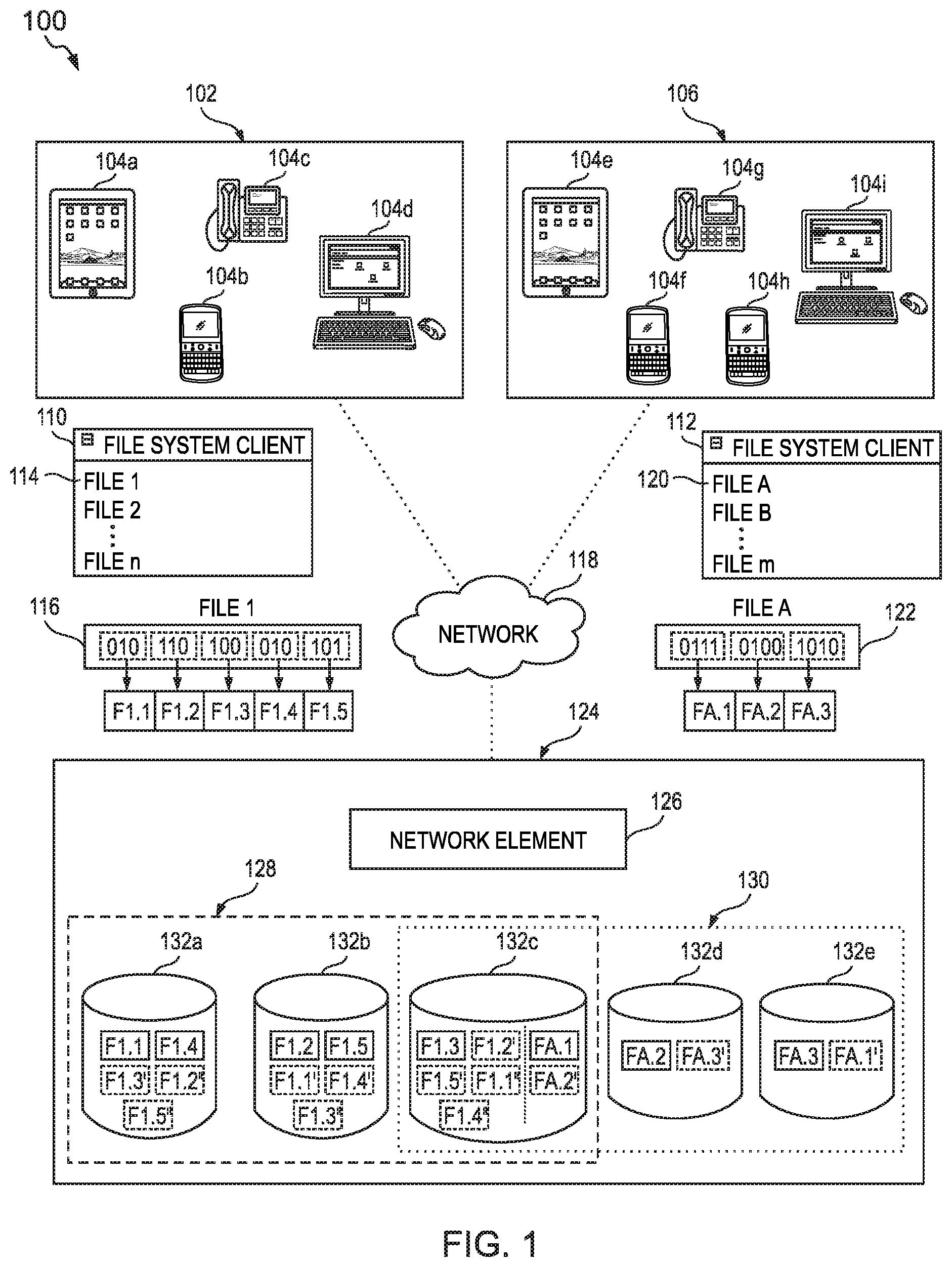
FIG. 1 is a simplified schematic diagram of a system comprising an object storage system (OSS) in which fragments of a file (i.e., objects) are stored in logical disks;
FIG. 2 is a simplified diagram of details of a network element and storage devices in a data center implementing the OSS of FIG. 1;
FIG. 3 is a simplified schematic diagram of logical disk metadata;
FIG. 4 is a simplified schematic diagram illustrating an exemplary endpoint;
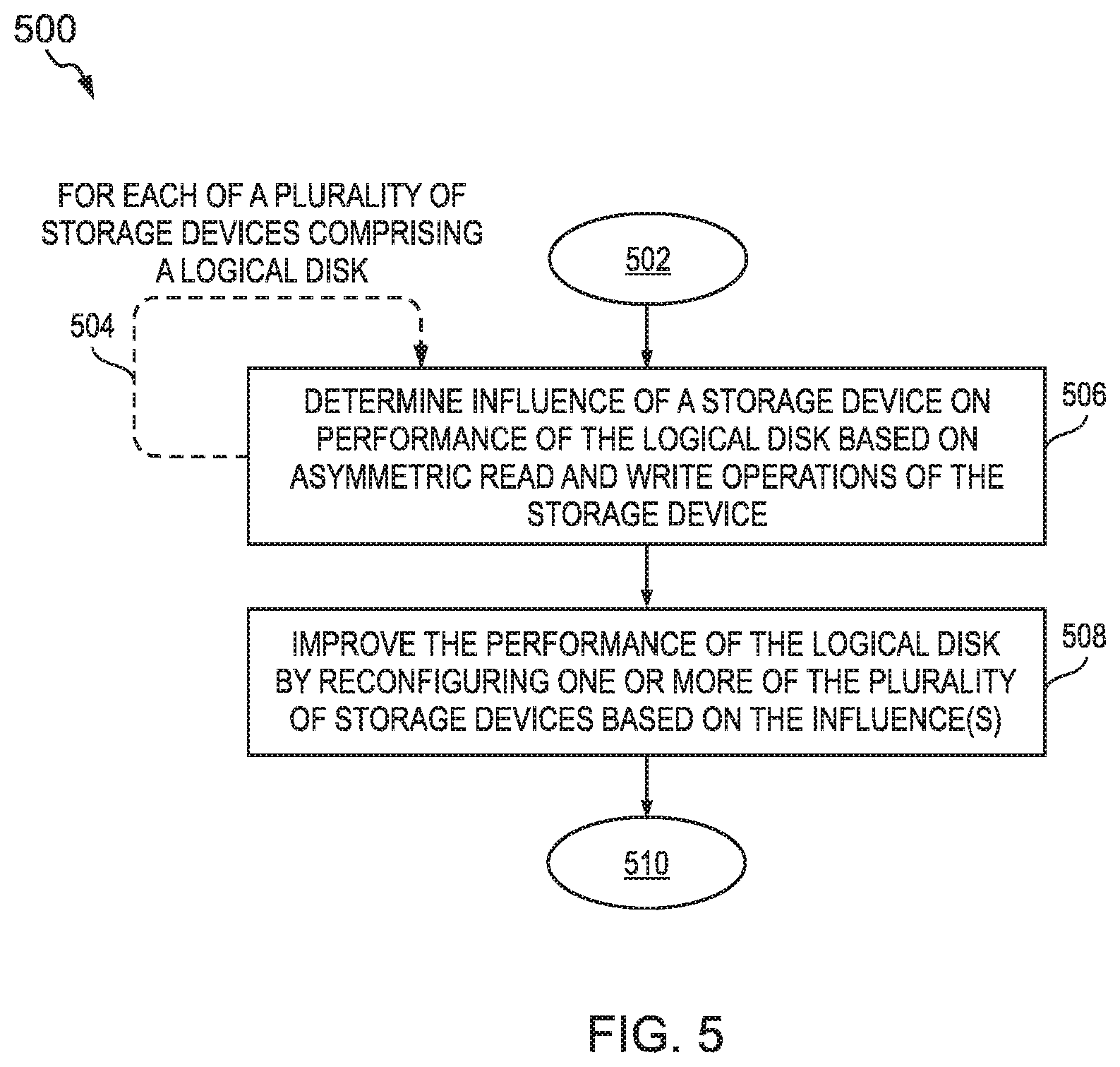
FIG. 5 is a simplified schematic diagram illustrating an exemplary logic for improving the performance of a logical disk according to some embodiments of the present disclosure;
FIG. 6 is a simplified schematic diagram illustrating another exemplary logic for improving the performance of a logical disk by reducing a latency of the logical disk according to some embodiments of the present disclosure;
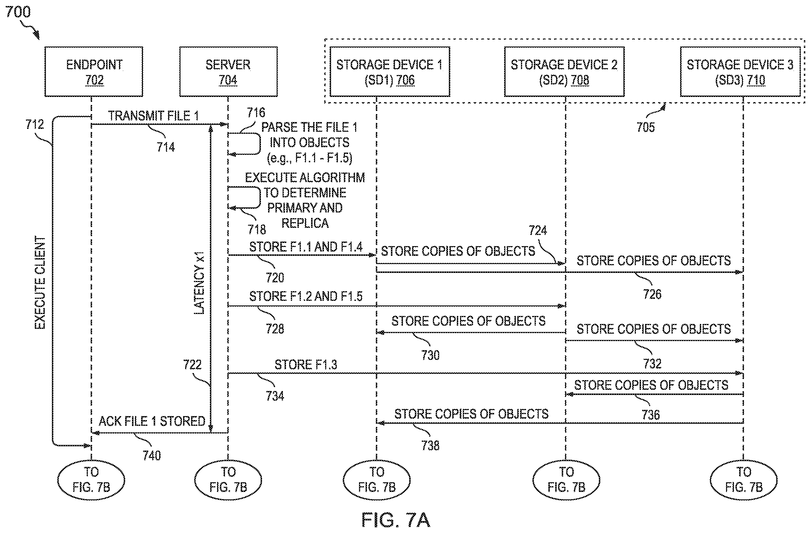
FIGS. 7A, 7B, 7C and 7D illustrate exemplary data transmissions between components of a system for improving the performance of a logical disk; and
FIG. 8 is an exemplary graphical interface for a logical disk management module.
DESCRIPTION OF EXAMPLE EMBODIMENTS OF THE DISCLOSURE
Overview
Example Embodiments
Some file storage systems store each complete and unmodified file in a contiguous block of memory in a storage disk. However, some object storage systems use a process, sometimes referred to as data striping, to split each file into several portions, called objects, before storing them in one or more storage devices. In other words, each object is a fragment of a file (e.g., each fragment being a subdivision of the file). It is noted that the terms `object` and `fragment` are used interchangeable in the present disclosure. In addition, each object may be replicated on more than one storage device. For example, when writing a file, the file is split into objects and each object may be stored on a storage device (a primary storage device) and a copy of the object may be stored on, e.g., one or more other storage devices (redundant storage devices referred to herein as replica storage devices). It is noted that each object of a single file need not have the same storage device as the primary storage device. Indeed, the objects that comprise a single file may be distributed and replicated across 100s of storage devices. When the file is read from the file system, each object is read only from the primary storage device. Thus, reading and writing an object is asymmetric in that reading the object from an object storage system (OSS) only requires accessing a single storage device (i.e., the primary storage device) while writing an object to the OSS requires accessing a several storage devices (i.e., the primary storage device and each of the replica storage devices). In many systems, it is desirable to keep latency down (e.g., low latency is preferred; high latency is undesirable). In general, this asymmetry causes objects to be read faster (e.g., lower latency) than they are written. Reading and writing files causes repeated reading and writing of objects, which further exacerbates the asymmetry.
An object storage system (OSS) is inclusive of a plurality of object storage devices (OSDs) for storing objects (i.e., the file fragments). An object storage device (OSD) is a storage device (e.g., physical or logical) in which the objects are stored. In many cases, an OSD is a physical storage device (including, e.g., a memory, a processor, a cache) but may also be inclusive of a logical disk (based on several physical devices or partitions of a single physical device). An OSD is a primary storage unit of an OSS. An OSD can include a client (e.g., code, software) that can be executed by an endpoint to access a logical disk using a file system interface. A `logical disk` is inclusive of a virtual storage device that provides access to memory that is located on one or more physical storage devices. For example, a logical disk may include memory from several different physical devices, each of which may be co-located (e.g., in a single data center) or may be remote from another (e.g., in different data centers). In addition, each physical device may have multiple partitions of memory each of which are can be used, by itself, as a logical disk or can be used in combination with memory from other storage devices to form the logical disk.
One problem that arises in file systems is how to determine the latency of a disk on which the files are stored. Computing latency is trivial for file systems that store files only on a local storage disk. Moreover, such calculations may be unnecessary since the disk is local and the files can be stored in a contiguous block of memory. For file systems that store (all) files of the logical disk in a single remote disk, the latency of the logical disk is simply the latency of the single remote disk. For file systems that store files in multiple remote disks, latency can be determined based on a latency of each remote disk and a weight value that accounts for a proportion of the logical disk stored in each remote disk. For example, the logical disk may store files in two remote disks, where 20 percent of the files of are stored in a first disk and 80 percent of the files are stored in a second disk. In such a case, the latency of the logical disk may be calculated as 0.2*(latency of the first disk)+0.8*(latency of the second disk). However, it is much more complicated to determine the latency of a logical disk for which the data is stored in an object storage system (e.g., based on the asymmetry of the reads/writes of objects) and the large number of storage devices that may be used for a single file. Thus, an objective technical problem is to determine the latency of a logical disk that asymmetrically reads object from and writes objects to the logical disk.
A file system may utilize an object storage system (OSS) as an underlying data storage system. For example, a service provider (or operator) may provide data storage as a service to endpoints using an OSS. Each endpoint may be associated with an entity (e.g., an individual or an organization). A tenant refers an entity associated with one or more endpoints each of which can receive, as a service from the service provider, access to the file system and/or the OSS. Each endpoint is associated with (e.g., belongs to and/or is operated by) at least one entity. As an example, a company (i.e., an organization that is a tenant of the service provider) may provide each of its employees with a mobile device (i.e., an endpoint). Each endpoint may acquire (e.g., download), from the service provider, a client module (e.g., code, software), which, when executed by the endpoint, generates a file system interface based on objects stored in the OSS. Thus, from the perspective of any endpoint that uses the client module and/or the file system interface to access the file system, the (complete and unmodified) files appear to be stored in a single directory. However, on the backend of the file system, each file is fragmented into objects and is stored across one or more storage devices.
The term `endpoint` is inclusive of devices used to initiate a communication, such as a computer, a personal digital assistant (PDA), a laptop or electronic notebook, a cellular telephone (e.g., an IPHONE, an IP phone, a BLACKBERRY, a GOOGLE DROID), a tablet (e.g., an IPAD), or any other device, component, element, network element, or object capable of initiating voice, audio, video, media, and/or data exchanges within system 100 (described below). An endpoint may also be inclusive of a suitable interface to the human user, such as a microphone, a display, or a keyboard or other terminal equipment. An endpoint may also be any device that seeks to initiate a communication on behalf of another entity or element, such as a program, a conferencing device, a database, or any other component, device, element, or object capable of initiating an exchange within the system 100. Furthermore, endpoints can be associated with individuals, clients, customers, or end users. Data, as used herein in this document, refers to any type of numeric, voice, messages, video, media, or script data, or any type of source or object code, or any other suitable information in any appropriate format that may be communicated from one point to another.
FIG. 1 illustrates an object storage system (OSS) used as a data storage system that underlies a file system. In particular, FIG. 1 illustrates, among other things, a system (i.e., system 100) comprising an object storage system (OSS) in which fragments of a file (i.e., objects) are stored in logical disks. The system 100 comprises tenants 102 and 106, file system interfaces 110 and 112, files 116 and 122, network 118, and data center 124. Each of the tenants 102 and 106 comprise a plurality of endpoints 104. The tenant 102 comprises endpoints 104a, 104b, 104c, and 104d. The tenant 106 comprises endpoints 104e, 104f, 104g, 104h, and 104i. Each of the endpoints 104a-104i (collectively referred to as endpoints 104) can access logical disks via a file system client interface (i.e., file system client interfaces 110 and 114). The endpoints 104 utilize the file system interfaces 110 or 112 to access (over the network 118) the files (e.g., files 116 or 112) from logical disks in the data center 124. The data center 124 comprises a network element 124 coupled to each of storage devices 132a-e. Each of the storage devices 132a-e is a physical storage device and is an object storage device (OSD) in the OSS. Each of the storage devices 132a-e is associated with one or more of logical disks 128 and 130. Fragments of the files are stored distributed across the storage devices 132a-e, which make up logical disks 128 and 130. Each of the logical disks stores fragments of a file in a primary storage device (within the logical disk) and one or more replica storage devices (within the same logical disk). In contrast, each the logical disks retrieves the fragments from the primary storage device and not the one or more replica storage devices. Thus, each logical disk asymmetrically stores fragments in and retrieves fragments from logical disks (e.g., based, at least in part, on retrieving a fragment from the logical drive accesses the storage devices a different number of times than for writing the fragment to the logical drive). It is noted that the data center 124 is illustrated with five storage devices (i.e., 132a-e) only for clarity and simplicity of the figures. In practice, the data center 124 may include any number of storage devices (in some cases of thousands of storage devices).
The network 118 operatively couples the tenants (i.e., 102 and 106) and the data center 124 to one another. The network 118 facilitates two-way communication between any two or more of the components of system 100. For example, each of the endpoints 104 can transmit to and/or receive data from the data center 124 (e.g., the network element 124, logical disks 128 and 138, and/or storage devices 132a-e therein) over the network 118. Within the context of the disclosure, a `network` represents a series of points, nodes, or network elements of interconnected communication paths for receiving and transmitting packets of information that propagate through a communication system. A network offers communicative interface between sources and/or hosts, and may be any local area network (LAN), wireless local area network (WLAN), metropolitan area network (MAN), Intranet, Extranet, Internet, WAN, virtual private network (VPN), or any other appropriate architecture or system that facilitates communications in a network environment depending on the network topology. A network can comprise any number of hardware or software elements coupled to (and in communication with) each other through a communications medium.
The data center 124 comprises a network element 126 and a plurality of storage devices 132a-132e. The network element 126 and each of the plurality of storage devices 132a-132e are operably coupled to one another by communication channels. The data center 124 includes two logical disks: logical disk 128 and logical disk 130. The logical disks 128 and 130 are associated with at with tenants 120 and 106 respectively. Each tenant is provided with access only to its logical disks (and not to logical disks that are associated with other tenants). The network element 126 may maintain metadata associated with the logical disks. In this example, each tenant is associated with a single logical disk only for clarity of the figures. Each tenant may be associated with any number of logical disks. The metadata may include data mappings that, at least in part, define the logical disks and identify a manner in which the logical disk operates. For example, the network element 126 can store data comprising: a mapping of each storage device to one or more logical disks, a mapping of each tenant to one or more logical disks; a mapping of each tenant to one or more storage devices; a mapping of each logical disk to operational variables that identify a manner in which a logical disk operates. The operational variable may include (but are not limited to): a size of each object to be stored in the logical disk (e.g., measured in bit or multiples thereof), a number of primary storage devices in which each object is to be stored, a number of replica storage devices in which each object is to be stored, pools of storage devices (e.g., subgroups of storage devices within a logical disk) for which one of the storage devices is primary storage device and others of the storage devices are replica storage devices, and/or any other parameters that define (or otherwise specify) a manner in which a logical disk operates. In this example, each of the storage devices 132a, 132b, and 132c is mapped to logical disk 128; each of the storage devices 132c, 132d, and 132e is mapped to logical disk 130; the tenant 102 is mapped to the logical disk 128; the tenant 106 is mapped to the logical disk 130; the logical disk 128 is associated with operational variables including: a fragment size of three bits, one primary storage device for each fragment, two replica storage devices for each fragment; and the logical disk 130 is associated with operational variables including: a fragment size of four bits, one primary storage device for each fragment, and one replica storage device for each fragment. It is noted that each logical disk may be mapped to a single logical disk or to multiple logical disks. In this example, the logical disks 128 and 130 share the storage device 132c.
As used herein in this Specification, the term `network element` is meant to encompass any as servers (physical or virtual), end user devices, routers, switches, cable boxes, gateways, bridges, load balancers, firewalls, inline service nodes, proxies, processors, modules, or any other suitable device, component, element, proprietary appliance, or object operable to exchange, receive, and/or transmit data in a network environment. These network elements may include any suitable hardware, software, components, modules, interfaces, or objects that facilitate the sharing of message queue operations thereof. This may be inclusive of appropriate algorithms and communication protocols that allow for the effective exchange of data or information. Each of the network elements can also include suitable network interfaces for receiving, transmitting, and/or otherwise communicating data or information in a network environment.
In one particular instance, the architecture of the present disclosure can be associated with a service provider deployment. For example, a service provider (e.g., operating the data center 124) may provide the tenants 102 and 106 with access to logical disks 128 and 130 in the data center 124. In other examples, the architecture of the present disclosure would be equally applicable to other communication environments, such as an enterprise wide area network (WAN) deployment. The architecture of the present disclosure may include a configuration capable of transmission control protocol/internet protocol (TCP/IP) communications for the transmission and/or reception of packets in a network.
The dashed lines between the network 118 and the tenants 102 and 106 (and the endpoints 104 therein) and the data center 124 represent communication channels. As used herein, a `communication channel` encompasses a physical transmission medium (e.g., a wire) or a logical connection (e.g., a radio channel) used to convey information signals (e.g., data, data packets, control packets, messages etc.) from one or more senders (e.g., an tenant, an endpoint, a network element, a storage device, and the like) to one or more receivers (e.g., a second data center, a second message queue, a message consumer, a network element, and the like). Data, as used herein, refers to any type of source or object code, object, fragment of a file, data structure, any type of numeric, voice, messages, video, media, or script data packet, or any other suitable information in any appropriate format that may be communicated from one point to another. A communication channel, as used herein, can include one or more communication links, which may be physical (e.g., wire) or logical (e.g., data link, wireless link, etc.). Termination points of communication channels can include network interfaces such as Ethernet ports, serial ports, etc. In some examples, each communication channel may be a single channel: deployed for both control messages (i.e., instructions to control a network element, a logical disk, and/or a storage device) and data messages (i.e., messages that include objects for storage in one or more storage devices).
The file system interfaces 110 and 112 are a graphical user interface for the file system that stores files in logical disks 128 and 130 (respectively) in the data center 124. Each of the endpoints 104 executes a code block to generate the file system Interface (i.e., interface 110 or 112) through which the endpoint can access the files in the file system. Each of the tenants is provided with access to one or more logical disks in the data center. Tenants have a corresponding customized file system interface through which to access to their logical disks (e.g., the interfaces are customized on a per-tenant basis). The file system interface 110 renders filenames (i.e., filenames "FILE 1", "FILE 2", . . . , "FILE n") for a directory location in the logical disk 128 associated with the tenant 102. The file system Interface 112 renders filenames (i.e., filenames "FILE A", "FILE B", . . . , "FILE m") for a directory location in the logical disk 130 associated with the tenant 106. Each of the filenames corresponds to a file. The filename 114 corresponds to file 116. The filename 120 corresponds to file 122. Within the file system interfaces 110 and 112, files appear to be complete, unmodified, and stored in a single directory. Thus, from the perspective of any of the endpoints 104 that use the file system interface, the (complete and unmodified) files appear to be stored in a single directory. However, within the data center 124, each file is fragmented into objects and is stored across one or more storage devices.
For example, each of the files 116 and 122 is fragmented into objects; the objects are stored distributed and replicated across several storage devices in a logical disk. The file 116 is named "FILE 1" and corresponds to the filename 114 in the file system interface 110. The file 122 is named "FILE A" and corresponds to the filename 120 in the file system interface 112. Each of the files 116 and 122 is stored, at least in part, in binary form. The files may be further encoded in a standardized encoding (e.g., ASCII, Unicode, BinHex, Uuencode, Multipurpose Internet Mail Extensions (MIME), multimedia encoding such as audio and/or video encoding) or a propriety encoding (e.g., a proprietary file type generated by proprietary software). The files are split into objects. Each object is a fragment of the file. A size of the objects (e.g., measured in bit, bytes, or any multiple thereof) is configurable (e.g., by an endpoint, a network element, and/or other computing element with administrative rights). Thus, each service provider, each tenant, each endpoint, and the like may customize the size of the object. In the example of system 100, one of the endpoints 104a-d has set the size of the object to 3 bits for all files associated with the tenant 102; one of the endpoints 104e-i has set the size of the object to 4 bits for all files associated with the tenant 106. The files 116 and 122 are split into objects based, at least in part, on the size of the object set for the corresponding tenant. The file 116 (i.e., "FILE 1") is split into five 3-bit objects (labeled "F1.1", "F1.2", "F1.3", "F1.4", and "F1.5"). The file 122 (i.e., "FILE A") is split into three 4-bit objects (labeled "FA.1", "FA.2", and "FA.3"). Each object (i.e., each fragment of the file) is asymmetrically stored in and retrieved from storage devices in the data center 124.
Each fragment of a file is asymmetrically stored in and retrieved from storage devices in the data center 124. Each fragment being stored in multiple storage devices makes the logical disk robust. A failure of any of the storage devices is less likely to cause a complete loss of any file or fragment thereof at least because each fragment is redundantly stored in multiples storage devices. If a storage device fails, copies of fragments stored on others of the storage devices can be used to reassign a primary and/or additional replica storage devices as needed. Each fragment is assigned a primary storage device and one or more replica storage devices from the storage devices associated with a logical disk. A primary storage device stores its assigned fragments and, when they are requested from the logical disk, the primary storage device retrieves the assigned fragments and transmits them to the requesting component. A replica storage device stores its assigned fragments and but is not responsible for retrieving the assigned fragments in response to requests. In other words, while the each fragment is stored in multiple storage devices (i.e., the primary and the replica storage devices) only one of the multiple storage devices responds to requests to read the fragment. Writing a fragment to the logical disk requires activity from several storage devices (i.e., the primary storage device and each of the replica storage devices) while reading the fragment from the logical disk only requires activity from the a single storage device (i.e., the primary storage device). Retrieving an object from the logical drive accesses the storage devices a different number of times than for writing the object to the logical drive.
Each object is stored in a primary storage device and one or more replica storage devices. In FIG. 1, the object, when stored in the primary storage device, is illustrated as a solid rectangle and, when stored in the replica storage devices, is illustrated as a dashed or dotted rectangle. A first copy of each object is labeled with a prime symbol ('); a second copy of each object is labeled with a double prime symbol (''). The file 116 (i.e., "FILE 1") is split into five 3-bit objects (labeled "F1.1", "F1.2", "F1.3", "F1.4", and "F1.5") and stored in the logical disk 128. The logical disk 128 comprises storage disks 132a and 132b and at least a portion of the storage disk 132c. Each object of File 1 is stored in a primary storage device and two replica storage devices. For example, for the object F1.1, the storage device 132a is the primary storage device (storing the object F1.1); the storage device 132b is a first replica storage device (storing the first copy F1.1'); and the storage device 132c is a second replica storage device (storing the first copy F1.1''). Table 1 below summarizes the primary storage devices and replica storage devices for each of the objects parsed from the FILE 1.
TABLE-US-00001 TABLE 1 Summary of primary storage devices and replica storage devices in the logical disk 128 for each of the objects parsed from the FILE 1. First Second Object Primary Replica Replica F1.1 132a 132b 132c F1.2 132b 132c 132a F1.3 132c 132a 132b F1.4 132a 132b 132c F1.5 132b 132c 132a
The file 122 (i.e., "FILE A") is split into three 4-bit objects (labeled "FA.1", "FA.2", and "FA.3") and stored in the logical disk 130. The logical disk 130 comprises storage disks 132d and 132e and at least a portion of the storage disk 132c. Each object of File A is stored in a primary storage device and a replica storage device. For example, for the object FA.1, the storage device 132c is the primary storage device (storing the object FA.1); and the storage device 132e is a first replica storage device (storing the first copy FA.1'). Table 2 below summarizes the primary storage devices and replica storage devices for each of the objects parsed from the FILE A.
TABLE-US-00002 TABLE 2 Summary of primary storage devices and replica storage devices in the logical disk 130 for each of the objects parsed from the FILE A. First Object Primary Replica FA.1 132c 132e FA.2 132d 132c FA.3 132e 132d
As discussed above, an objective technical problem is to determine the latency of a logical disk that asymmetrically reads and writes objects, as is the case for logical disks 128 and 130. The following is a practical example of such a problem. In a cloud computing environment (e.g., the cloud computing software marked under the trade name OpenStack) with an object storage system (e.g., the storage system marketed under the trade name CEPH) as the backend storage, it is common for an operator (e.g., a service provider) to have difficulties identifying a reason why a tenant's logical disk (e.g., a Ceph volume) is "slow" (i.e., read and/or write operations to the logical disk have a latency that negatively impacts performance of the system and/or is unacceptable to the tenant). When a tenant reports, to the operator, that their logical disk is slow, operators are neither able to validate the report nor identify the reasons for the logical disk being slow. Because the logical disk volume is distributed across potentially thousands of physical disks (e.g., storage devices), isolating the problem to one or more disks can be a challenge.
A potential solution is to empirically determine the latency of a disk. In traditional distributed storage systems, latency can be calculated through experiments based on request and response (completion) of events. This method of latency calculation cannot be applied to determine latency of a logical disk (such as logical disks 128 and 130 of FIG. 1) because the entire logical disk is not read from or written to a single physical disk. Also, calculating latency of a logical disk in object-based storage (e.g., in object storage systems) is challenging because there may be multiple objects belonging to a same logical disk stored in a same storage device. In other words, if all of the objects were retrieved from the logical disk, some of the storage devices would have to retrieve more objects than others of the storage devices. Thus, the storage devices that perform more retrieving would have a higher influence on the performance of the logical disk than the others of the storage devices. Another possible solution is to manually debug a logical disk by manually inspecting each of the associated storage devices to identify any latency issues; this is time consuming, inefficient, and prone to errors and oversights.
A solution, disclosed in the present disclosure, to address the above issues (and others) provides for improving performance of a logical disk by reconfiguring storage devices in the logical disk based on asymmetric reading and writing characteristics of the storage devices. The methods, systems, logic, and/or apparatuses (as disclosed herein) address the above technical problem (and others) by adding and/or removing storage devices from the logical disk based on an influence that each of the exiting storage devices in the logical disk has on the overall performance of the logical disk. In some examples, the methods, systems, logic, and/or apparatuses disclosed herein utilize a number of objects that a storage device is associated with retrieving and a different number of objects that the storage device is associated with storing to determine the influence on the logical disk. In addition, the adding or removing of the storage device can be simulated using a mathematical model of the logical disk to verify whether the addition or removal (as the case may be) of the storage device will improve the performance of the logical disk.
FIG. 2 is a simplified diagram of details of the network element 126 and storage devices 132a-c in the data center 124 implementing the object storage system (OSS) of FIG. 1. FIG. 2 illustrates a portion of the storage devices 132 (i.e., illustrates storage devices 132a-c and not storage devices 132d-e) only clarity of the Figure.
The network element 126 of FIG. 2 is an example of the network element 126 of FIG. 1 and/or of the server 704 (of FIGS. 7A-7D, which are described below). The network element 126 comprises a processor 202, a memory element 204, a data bus 208, a network interface 210, and a logical disk management module 214. The data bus 208 operably couples the components to one another. The network interface 210 includes a plurality of ports 212, each of which is configured to transmit and/or receive data over a network. The memory element 204 stores, among other things, logical disk metadata 206 and a distributed storage code block 207. The logical disk metadata 206 is inclusive of the mappings (defining the logical disks and/or identifying a manner in which the logical disk operates) described with respect to FIG. 1, the data of Table 1 (of the present disclosure), the data of Table 2 (of the present disclosure), and/or the data of FIG. 3 (which is described below). The processor 202, among other things, executes the distributed storage code block 207 that, at least in part defines and manages an object storage system in the data center 124. When executed, the distributed storage code block 207, can generate control plane messages for communication with corresponding distributed storage code blocks in other components of the logical disk (e.g., distributed storage code block 226a-c in the storage devices 132a-c). Moreover, each distributed storage code block the logical disk may include libraries of functions to operate the OSS (e.g., algorithms for pseudo-randomly distributing objects and copies to storage devices, data striping algorithms for fragmenting a file into objects, and the like). As an example, a distributed storage code block may be client, a daemon, or an operating system for the device to operate within the object storage system. As a further example, each distributed storage code block may be a CEPH daemon (e.g., a Cluster monitor daemon, a metadata server daemon, an object storage device daemon). In such an example, the distributed storage code block 207 may be a metadata server daemon and each of the distributed storage code block 226a-c may be an object storage device daemon. In addition, the processor 202 executes code corresponding to the logical disk management module 214 and accesses data from the memory element 204 to manage, using the code, a logical disk and improve its performance by exploiting the asymmetric reading and writing characteristics of the storage devices of the logical disk. The logical disk management module 214 (and the corresponding code) includes logic for improving the performance of a logical disk.
Each of the storage devices 132a-c comprises respective processors 216a-c, network interfaces 218a-c, and memory elements 222a-c. Each of the network interfaces 218a-c includes a respective plurality of ports 220a-c, each of which is configured to transmit and/or receive data over a network. Each of the memory elements 222a-c stores, among other things, a distributed storage code block 226a-c. The processors 216 execute the distributed storage code blocks 226a, which, at least in part, define and manage an object storage system in the data center 124. When executed, each of the distributed storage code blocks 216a-c, can generate control plane messages for communication with corresponding distributed storage code blocks in other components of the logical disk (e.g., distributed storage code block 207 in the network element 126). Moreover, each distributed storage code block the logical disk may include libraries of functions to operate the OSS (e.g., algorithms for distributing objects to storage devices and/or copying objects to replica storage devices). Each of the storage devices 132a-c has a portion of their memory element dedicated to storing objects. Storage device 132a include memory portion 224a, which stores objects (and copies of objects) associated with files stored in the logical disk 128 of FIG. 1. Storage device 132b include memory portion 224b, which stores objects (and copies of objects) associated with files stored in the logical disk 128 of FIG. 1. Storage device 132c include memory portion 224c, which stores objects (and copies of objects) associated with files stored in the logical disk 128 of FIG. 1. The details of the objects and the copies stored in the logical disk 128 are provided in the Table 1 and the corresponding description; the details are omitted here only for the purpose of brevity of the specification.
FIG. 3 is a simplified schematic diagram of logical disk metadata. In this example, the metadata is a table that identifies, for each of a plurality of storage devices, at least one impact factor. The columns of the table 300 include column 302 identifying a logical disk identifier (ID); column 304 identifying a storage device ID; column 306 identifying a read impact factor for the corresponding combination of the logical disk ID and the storage device ID; column 308 identifying a write impact factor the corresponding combination of the logical disk ID and the storage device ID; and column 310 identifying a latency for the corresponding storage device ID (measured in milliseconds, ms).
The table 300 includes metadata corresponding to the storage devices 132a-e and the logical disks 128 and 130 in the data center 124 of FIG. 1. In particular, the logical disk 128 corresponds to the logical disk ID "1"; the logical disk 130 corresponds to the logical disk ID "2"; the storage device 132a corresponds to the storage device ID "1"; the storage device 132b corresponds to the storage device ID "2"; the storage device 132c corresponds to the storage device ID "3"; the storage device 132d corresponds to the storage device ID "4"; and the storage device 132e corresponds to the storage device ID "5".
The row 312 corresponds to metadata associated with the storage device ID 1 (i.e., the storage device 132a) within the context of the logical disk ID 1 (i.e., the logical disk 128). The row 314 corresponds to metadata associated with the storage device ID 2 (i.e., the storage device 132b) within the context of the logical disk ID 1 (i.e., the logical disk 128). The row 316 corresponds to metadata associated with the storage device ID 3 (i.e., the storage device 132c) within the context of the logical disk ID 1 (i.e., the logical disk 128). The row 318 corresponds to metadata associated with the storage device ID 3 (i.e., the storage device 132c) within the context of the logical disk ID 2 (i.e., the logical disk 130). The row 320 corresponds to metadata associated with the storage device ID 4 (i.e., the storage device 132d) within the context of the logical disk ID 2 (i.e., the logical disk 130). The row 322 corresponds to metadata associated with the storage device ID 5 (i.e., the storage device 132e) within the context of the logical disk ID 2 (i.e., the logical disk 130).
Each of the rows of the table 300 identifies a combination of a logical disk ID and a storage device ID and corresponding performance parameters for the combination. The rows identify the combination of the logical disk ID and the storage device ID at least because each storage device may be associated with more than one logical disk. For example, the storage device ID 3 (i.e., the storage device 132c) is associated with both the logical disk IDs 1 and 2 (i.e., the logical disks 128 and 130, respectively) and, as a result, the table 300 contains two rows (i.e., rows 316 and 318) that identify the metadata for the storage device ID 3: one for each of the logical disk IDs 1 and 2.
Each impact factor identifies, on a per logical disk basis, a proportion of objects stored in or retrieved from each of the plurality of storage devices relative to others of the plurality of storage devices based on asymmetrical storage in and retrieval from each of the plurality of storage devices. The impact factors correspond to an influence that each of the storage devices has on the performance (e.g., average latency, amount of throughput, and the like) of the logical disks to which the storage device is associated. For example, as the amount of throughput (e.g., a computational load) on each storage device increases, the latency of each storage device increases because it takes more the time to process each read/write request than if the amount of throughput were reduced.
A network element (e.g., a server, such as a metadata server in a CEPH system), may calculate the impact factors by, at least in part, counting a number of objects for which each of the plurality of storage devices is a primary storage device and/or a replica storage device.
The read impact factor (i.e., in column 306) identifies a number of objects for which each of the storage devices is a primary storage device within the context of a logical disk. The network element may calculate the read impact factor based on metadata associated with the logical disk and/or data retrieved from the storage devices. For example, the network element may utilize metadata including the data of Tables 1 and 2 of the present disclosure to count the number of objects for which each of the storage devices is a primary storage device within the context of a logical disk. In other examples, the network element may transmit to each storage device in a logical disk a request for a read impact factor. The request for the read impact factor may be for a single file, multiple files, or for all files for which the storage device stores objects (based on identifiers of files and/or objects in the request). The request may also identify a particular logical disk for which the impact factor is requested (e.g., since the impact factor may be different for each logical disk to which the storage device is associated).
Assuming, only for the sake of an simple example, that each logical disk only stores a single file (e.g., FILE 1 or File A), the read impact factor for each device is the number times that the storage device is identified in the column labeled "Primary" in Tables 1 and 2 (i.e., the number of objects for which the device is the primary storage device, which responds to read requests for the object). Table 1 includes metadata for the logical disk 128 (logical disk ID 1 in FIG. 3). The storage device 132a (storage device ID 1 in Table 300 of FIG. 3) is listed twice in the "Primary" column in Table 1 (for objects F1.1 and F1.4), which corresponds to the read impact factor of 2 in row 312 of table 300 in FIG. 3. The storage device 132b (storage device ID 2 in Table 300 of FIG. 3) is listed twice in the "Primary" column in Table 1 (for objects F1.2 and F1.5), which corresponds to the read impact factor of 2 in row 314 of table 300 in FIG. 3. The storage device 132c (storage device ID 3 in Table 300 of FIG. 3) is listed once in the "Primary" column in Table 1 (for objects F1.3), which corresponds to the read impact factor of 1 in row 316 of table 300 in FIG. 3. Table 2 includes metadata for the logical disk 130 (logical disk ID 2 in FIG. 3). The storage device 132c (storage device ID 3 in table 300 of FIG. 3) is listed once in the "Primary" column in Table 2 (for objects FA.1), which corresponds to the read impact factor of 1 in row 318 of table 300 in FIG. 3. The read impact factors of 1 in rows 320 and 322 of table 300 (for storage devices 132d and 132e (storage device IDs 4 and 5), respectively) are calculated in a manner similar to that for row 318.
The above process is described with respect to calculating the read impact factor of various storage devices for a single file. Object storage systems often store many files. The impact factor for all of the files in the logical disk may be calculating by repeating, for each file in the logical disk, the above-described process of calculating impact factors for a single file. The overall read impact factor for each storage devices in the logical disk may be calculated by summing the individual read impact factors (for each file) for each storage device to determine.
The write impact factor (i.e., in column 308) identifies a sum of: a first number of objects for which each of the storage devices is a primary storage device, and a second number of objects for which each of the storage devices is a replica storage device. A network element may calculate the write impact factor based on metadata associated with the logical disk and/or data retrieved from the storage devices. For example, the network element may utilize metadata including the data of Tables 1 and 2 of the present disclosure to count the number of objects for which each of the storage devices is a primary storage device and the number of objects for which each of the storage devices is a replica storage device within the context of a logical disk. In other examples, the network element may transmit to each storage device in a logical disk a request for a write impact factor. The request for the write impact factor may be for a single file, multiple files, or for all files for which the storage device stores objects (based on identifiers of files and/or objects in the request). The request may also identify a particular logical disk for which the impact factor is requested (e.g., since the impact factor may be different for each logical disk to which the storage device is associated).
The following example assumes (only for the sake of a simple example) that each logical disk only stores a single file (e.g., FILE 1 or File A). In such an example, the write impact factor for each device is the sum of (1) a number times that the storage device is identified in the column labeled "Primary" in Tables 1 and 2 (i.e., the number of objects for which the device is the primary storage device), and (2) a number times that the storage device is identified in any of the remaining "Replica" columns in Tables 1 and 2 (i.e., the number of objects for which the device is a replica storage device, which responds to write requests for the object). Table 1 includes metadata for the logical disk 128 (logical disk ID 1 in FIG. 3). The storage device 132a (storage device ID 1 in table 300 of FIG. 3) is listed twice in the "Primary" column in Table 1 (for objects F1.1 and F1.4) and is listed three times in the "Replica" columns in Table 1 (first replica for object F1.3 and second replica for objects F1.2 and F1.5); this corresponds to the write impact factor of (2+3) 5 in row 312 of table 300 in FIG. 3. The write impact factors of 5 in rows 314 and 316 of table 300 (for storage devices 132b and 132c (storage device IDs 2 and 3), respectively) are calculated in a manner similar to that for row 312. Table 2 includes metadata for the logical disk 130 (logical disk ID 2 in FIG. 3). The storage device 132c (storage device ID 3 in table 300 of FIG. 3) is listed once in the "Primary" column in Table 2 (for objects FA.1) and is listed once in the "Replica" column in Table 2 (for object FA.2); this corresponds to the write impact factor of (1+1) 2 in row 318 of table 300 in FIG. 3; this corresponds to the read impact factor of 1 in row 318 of table 300 in FIG. 3. The read impact factors of 1 in rows 320 and 322 of table 300 of table 300 (for storage devices 132d and 132e (storage device IDs 4 and 5), respectively) are calculated in a manner similar to that for row 318.
The impact factors are attributes that can be used to determine the influence that each storage device has on a logical disk by accounting for asymmetric read and write operations of the storage device. Other attributes may be used to determine the influence that each storage device has on a logical disk. Other attributes may include (but are not limited to) any one or more of the following attributes of a storage device: a number of pending operations (e.g., a number of operations in a queue of operations to be performed by the storage device), a number of stored objects (e.g., a total number of objects stored by the storage device across all of the logical disks with which it is associated), total number of logical disks using the storage device, and/or system metrics (e.g., performance parameters, a latency of input/output ("I/O") operations measured during a window of time, current processor utilization, current memory utilization, and the like). For example, as the current utilization of the processor (e.g., percent of processor capacity utilized by currently executing processes) increases for each storage device, the influence that each storage device has on latency of the logical disk increases because it takes more the time for each storage device to process each read/write request than if the current utilization were reduced.
The attributes may be requested directly from each storage device or may be calculated. In the example of latency, a latency of I/O operations performed by a storage device may be calculated by dividing a number of operations performed by the storage device (during in a window of time) divided by the length of time interval (e.g., measured seconds, minutes, or multiples thereof) to get average latency of the I/O operations. In some examples, the window of time is a moving time window (e.g., a most recent window of 15 minutes, 30 minutes, 1 hour, and the like).
After the attributes are collected for (e.g., calculated and/or retrieved from) each of the storage devices in a logical disk known, a numerical representation of an influence that each storage device has on operational performance the logical disk is determined. The numerical representation corresponds to a proportion of the operational performance of the logical device that is attributable to each of the plurality of storage devices based, at least in part, on the attributes of each of the storage devices. The numerical representation of the influence of each storage device may be determined using a mathematical model. In some examples, the numerical representation is a weighting factor for each of the plurality of storage devices.
A weighting factor for each of the storage devices can be calculated based one or more of the attributes of the each of the storage devices. The weighing factors may be percentage values that correspond to the asymmetric reading and writing characteristics of the storage devices of the logical disk. A weighting factor for a storage device is determined, at least in part, based on an impact factor of the storage device. In some examples, the weighting factor is determined based only on the impact factor(s). The following illustrates example calculations for determining the weighting factors is determined based only on impact factors. Weighting factors are calculated in the context of a logical disk (e.g., on a per-logical disk basis). Returning to table 300 of FIG. 3, the rows 312, 314, and 316 identify metadata for the logical disk ID 1 (logical disk 128 of FIG. 1) and the rows 318, 320, and 322 identify metadata for the logical disk ID 2 (logical disk 130 of FIG. 1). Example weighting factors (e.g., percentage values) for the logical disk ID 1 can be determined by dividing each impact factor by the sum of all of the impact factors (i.e., summing all of the read and write impact factors together ting factors). The sum of all of the read and write impact factors for logical disk ID 1 is 2+2+1+5+5+5=20 (the logical disk sum). The sum of the read and write impact factors for a storage device is divided by the logical disk sum to determine the weighting factor. Thus, the weighting factor for the storage device ID 1 (i.e., row 312) is (2+5)/20=7/20=0.35 (i.e. the sum of the read impact factor and the write impact factor, divided by logical disk sum). The weighting factor for the storage device ID 2 (i.e., row 314) is (2+5)/20=7/20=0.35. The weighting factor for the storage device ID 3 (i.e., row 316) is (1+5)/20=6/20=0.3. Similarly, the sum of all of the read and write impact factors for logical disk ID 2 is 1+1+1+2+2+2=9 (the logical disk sum). The weighting factor for the storage device ID 3 (i.e., row 318) is (1+2)/9=3/9 0.333. The weighting factor for the storage device ID 4 (i.e., row 320) is (1+2)/9=3/9=0.333. The weighting factor for the storage device ID 5 (i.e., row 322) is (1+2)/9=3/9=0.333. In this example, the weighting factor is a proportion of all of the impact factors (for the logical disk) that is attributable to each storage device (e.g., for each logical disk, sum of the weighing factors is equal to 1). The weighting factors are summarized in Table 3 below.
TABLE-US-00003 TABLE 3 Summary of weighting factors for storage devices in Logical Disk IDs 1 and 2. Logical Storage Weighting Disk ID Device ID Factor 1 1 0.35 1 2 0.35 1 3 0.3 2 3 0.333 2 4 0.333 2 5 0.333
In other examples, the weighting factor is determined based on the impact factor(s) in combination with one or more other attributes. For example, a mathematical algorithm (e.g., regression algorithm performing a regression analysis) may be executed on impact factor in combination with one or more other attributes to determine weighting factors for the storage device. As a further example, a simulation may be executed be under various conditions of storage disks (e.g., various pseudo-random distributions of objects across the of storage disks, various numbers of pending operations, and various system metrics). A (theoretical) latency of the logical disk can be determined from such simulations. A regression algorithm may take as input: (1) independent variables or factors (e.g., impact factor(s), number of pending operations, number of stored objects, system metrics, and the like) and dependent variables such as a latency of a logical disk (i.e., determined based on the simulations). The regression algorithm may generate, as output, weights to satisfy the following equation for latency of a logical disk (LDLatency):
LDLatency=sum[WF(i)*LS(i)], for i=1, 2, . . . , n; where n is the number of storage devices in the Logical Disk
Where LS(i) and the latency of the ith storage device;
WF is the weighting factor for the storage device;
WF=sum[x(j)*f(j)], for j=1, 2, . . . , m; where m is the number of factors input for the storage devices; and
f(j) is the jth factor for the storage device (e.g., factors such as impact factor(s), number of pending operations, number of stored objects, system metrics, and the like)
x(j) is the jth weight associated with the jth factor.
The regression algorithm is utilized to generate the weights (i.e., x(j)). Once the weights are known, they are used to determine LDLatency in a production environment (for actual storage devices and not simulated storage devices). The mathematical algorithm can be executed on the fly (e.g., in near real-time) and at regular intervals to track the influence of a storage device over time.
The above examples of calculating the weighting factors are provided for illustration purposes only (and do not limit the teaching of the present disclosure). Indeed, the teachings of the present disclosure are equally applicable to any approach of calculating the weighting factors as long as the approach accounts for the asymmetric reading and writing characteristics of the storage devices of the logical disk, as is demonstrated by the above exemplary approaches.
A portion of a performance parameter of a logical device that is attributable to each storage device in the logical device is calculated based, at least in part, on a corresponding performance parameter of each storage device weighted by the corresponding influence. In the example of latency, a weighted latency for a storage device can be calculated based on latency of I/O operations of the storage device and the weighting factor for the storage device. The weighted latency of the storage device is a portion of latency of the logical disks that is attributable to the storage device. For example, the weighted latency of the storage device (WLatency) is calculated by multiplied the weighting factor for the storage device (WF) and the latency of the storage device (LS) (i.e., WLatency=WF*LS). In some examples, the latency of the storage device (LS) is the latency of the I/O operations measured during a window of time. A calculation can be performed for each of a plurality of plurality of storage devices comprising logical disk. In such an example, for each of the plurality of storage devices, the latency of the I/O operations is multiplied by the weighting factor to determine a weighted latency for each of the plurality of storage devices. Table 300 (in FIG. 1) lists, in column 310, an average latency for each of the storage device. The weighted latency for each of the storage devices can be calculated by multiplying the average latency (from table 300) of each storage device by the corresponding weighting factors (from table 3). The weighted latency for the storage device ID 1 (i.e., row 312 of table 300 in FIG. 1) is 11 ms*0.35=3.85 ms. The weighted latency for the storage device ID 2 (i.e., row 314 of table 300 in FIG. 1) is 14 ms*0.35=4.9 ms. The weighted latency for the storage device ID 3 within logical disk ID 1 (i.e., row 316 of table 300 in FIG. 1) is 16 ms*0.3=4.8 ms. The weighted latency for the storage device ID 3 within logical disk ID 2 (i.e., row 318 of table 300 in FIG. 1) is 16 ms*(1/3)=5.333 ms. The weighted latency for the storage device ID 4 (i.e., row 320 of table 300 in FIG. 1) is 9 ms*(1/3)=3 ms. The weighted latency for the storage device ID 5 (i.e., row 322 of table 300 in FIG. 1) is 4 ms*(1/3) 1.333 ms. The weighted latencies are summarized in Table 4 below.
TABLE-US-00004 TABLE 4 Summary of weighted latencies for storage devices in Logical Disk IDs 1 and 2. Logical Storage Weighted Disk ID Device ID Latency (ms) 1 1 3.85 1 2 4.9 1 3 4.8 2 3 5.333 2 4 3.0 2 5 1.333
A performance parameter of a logical disk can be calculated based, at least in part, on corresponding performance parameters each of the storage devices and the weighting factor. Thus, the performance parameter of the logical disk can be calculated by summing the weighted performance parameter for each of the plurality of storage devices in the logical disk. In one example, a latency of the logical disk is calculated by summing the weighted latency for each of the plurality of storage devices in the logical disk. Thus, the latency of a logical disk=sum[W(i)*Latency(i)] (for i=1, 2, . . . , n; where n is the number of storage devices in the Logical Disk). For example, the logical disk ID 1 (rows 312, 314, and 316 of FIG. 1) has a calculated latency equal to the sum of the corresponding weighted latencies in table 4; the calculated latency of the logical disk ID 1 is (3.85 ms+4.8 ms+4.9 ms)=13.55 ms. The logical disk ID 2 (rows 318, 320, and 322 of FIG. 1) has a calculated latency equal to the sum of the corresponding weighted latencies in table 4; the calculated latency of the logical disk ID 2 is (5.333 ms+3 ms+1.333 ms)=9.666 ms.
A proportion of the performance parameter of a logical device that is attributable to each of the plurality of storage devices is calculated based, at least in part, an impact factor and a latency of each of the plurality of storage devices. For example, the proportions can be determined using the calculations discussed with respect to tables 3 and 4, which are based on the impact factors and latencies of table 300 of FIG. 1. The portion of the performance parameter attributable to each storage device (e.g., from table 4) can be divided by the performance parameter of the logical disk (e.g., the calculated latency of the logical disk) to identify (for each storage device) the proportion (e.g., percent contribution) of the performance parameter of the logical disk. As described above, the calculated latency of the logical disk ID 1 is 13.55 ms and the calculated latency of the logical disk ID 2 is 9.666 ms. Thus, the proportion of latency for each storage device is the weighted latency (from table 4) divided by the calculated latency of the corresponding logical disk. For the logical disk ID 1, the proportion attributable to storage device ID 1 is (3.85/13.55 ms) 28.4%, the proportion attributable to storage device ID 2 is (4.9/13.55 ms) 36.2%, and the proportion attributable to storage device ID 3 is (4.8/13.55 ms) 35.4%.
When the influence of each of the storage devices on a performance parameter of the logical disk is known, the performance of the logical disk is improved by reconfiguring one or more of the plurality of storage disks based on the influences. For example, a network device or endpoint may automatically (e.g., without any further input or prompting) toggle a storage device on or off and, thereby, improves the overall performance (e.g., reduces latency) of the logical disk.
The performance parameters of each storage device can have an unexpected impact on the performance parameter of the logical disk due to the objects being asymmetrically stored in and retrieved from the storage devices (and/or being pseudo-randomly distributed across the storage devices). In the example of table 300 (FIG. 1), the storage disk ID 3 has the highest latency (i.e., 16 ms) in logical disk ID 1 (i.e., relative to all other storage devices in logical disk ID 1). If the logical disk is reconfigured based only on latency (e.g., removing the storage device with the highest latency), then logical disk ID 3 may be identified for removal from the logical disk. However, the storage disk ID 3 does not contribute the highest proportion of latency to the calculated latency of the logical disk ID 1. Instead, the storage disk ID 2 contributes the highest proportion (i.e., 36.2%) of latency to the calculated latency of the logical disk ID 1 due, at least in part, to the impact factors (and the weighting factor derived therefrom) for the storage disk ID 2. The storage disk ID 2 has a more of an influence on the performance parameter of the logical disk than others of the storage disks.
FIG. 4 is a simplified schematic diagram illustrating an exemplary endpoint (i.e., endpoint 104), according to some embodiments of the present disclosure. The endpoint 104 of FIG. 4 is an example of any of the endpoints 104a-i of FIG. 1 and/or the endpoint 705 of FIGS. 7A-7D. The endpoint 104 comprises a processor 402, a memory element 402, a data bus 410, a network interface 412, and a logical disk management module 416. The data bus 410 operably couples the components to one another. The network interface 412 includes a plurality of ports 414, each of which is configured to transmit and/or receive data over a network. The memory element 402 includes a file system code block 406 and a logical disk metadata 408. The processor 402, among other things, executes the file system code block 406 to access files stored in a logical disk. In some examples, when executed by the processor 404, the file system code block 406 generates a file system interface (e.g., similar to the file system interface 110 or 112 of FIG. 1) for accessing the files stored in the logical disk. In addition, the processor 402 executes code corresponding to the logical disk management module 416 and accesses data from the memory element 404 to manage, using the code, a logical disk and improve its performance by exploiting the asymmetric reading and writing characteristics of the storage devices of the logical disk. The logical disk management module 416 (and the corresponding code) includes logic for improving the performance of a logical disk.
In one implementation, the network elements, endpoints, servers, and/or storage devices, described herein may include software to achieve (or to foster) the functions discussed herein for improving performance of logical disks where the software is executed on one or more processors to carry out the functions. This could include the implementation of instances of file system clients, logical disk metadata, logical disk management modules, distributed storage code blocks, and/or any other suitable element that would foster the activities discussed herein. Additionally, each of these elements can have an internal structure (e.g., a processor, a memory element, etc.) to facilitate some of the operations described herein. In other embodiments, these functions for improving performance of logical disks may be executed externally to these elements, or included in some other network element to achieve the intended functionality. Alternatively, network elements, endpoints, servers, and/or storage devices may include software (or reciprocating software) that can coordinate with other network elements/endpoints in order to achieve the performance improvement functions described herein. In still other embodiments, one or several devices may include any suitable algorithms, hardware, software, components, modules, interfaces, or objects that facilitate the operations thereof.
In certain example implementations, the performance improvement functions outlined herein may be implemented by logic encoded in one or more non-transitory, tangible media (e.g., embedded logic provided in an application specific integrated circuit [ASIC], digital signal processor [DSP] instructions, software [potentially inclusive of object code and source code] to be executed by one or more processors, or other similar machine, etc.). In some of these instances, one or more memory elements can store data used for the operations described herein. This includes the memory element being able to store instructions (e.g., software, code, etc.) that are executed to carry out the activities described in this Specification. The memory element is further configured to store databases such as mapping databases (mapping various aspects of a logical disk to storage devices, clients, or other metadata) to enable performance improvements of a logical disk as disclosed herein. The processor can execute any type of instructions associated with the data to achieve the operations detailed herein in this Specification. In one example, the processor could transform an element or an article (e.g., data) from one state or thing to another state or thing. In another example, the activities outlined herein may be implemented with fixed logic or programmable logic (e.g., software/computer instructions executed by the processor) and the elements identified herein could be some type of a programmable processor, programmable digital logic (e.g., a field programmable gate array [FPGA], an erasable programmable read only memory (EPROM), an electrically erasable programmable ROM (EEPROM)) or an ASIC that includes digital logic, software, code, electronic instructions, or any suitable combination thereof.
Any of the devices disclosed herein (e.g., the network elements, endpoints, servers, storage devices, etc.) can include memory elements for storing information to be used in achieving the performance improvements, as outlined herein. Additionally, each of these devices may include a processor that can execute software or an algorithm to perform the activities as discussed in this Specification. These devices may further keep information in any suitable memory element [random access memory (RAM), ROM, EPROM, EEPROM, ASIC, etc.], software, hardware, or in any other suitable component, device, element, or object where appropriate and based on particular needs. Any of the memory items discussed herein should be construed as being encompassed within the broad term `memory element.` Similarly, any of the potential processing elements, modules, and machines described in this Specification should be construed as being encompassed within the broad term `processor.` Each of the devices can also include suitable interfaces for receiving, transmitting, and/or otherwise communicating data or information in a network environment.
FIG. 5 is a simplified schematic diagram illustrating an exemplary logic (i.e., logic 500) for f according to some embodiments of the present disclosure. Procedure 502 may coincide with a start or end point of other logic, routines, and/or applications. In addition, at 502, data (e.g., data structures, objects, values, variables, etc.) may be initialized, retrieved, or accessed for use in logic 500. At 506, an influence of a storage device on performance of a logical disk based on asymmetric read and write operations of the storage device. As generally indicated by 504, the determination may be made for each of a plurality of storage device that comprise the logical disk. At 508, the performance of the logical disk is improved by reconfiguring one or more of the plurality of storage disks based on the influence(s). The logic 500 ends at 510. 510 may coincide with a start or end point of other logic, routines, and/or applications.
At a high level, the logic 500, when executed, improves the performance of a logical disk. Logic 500 may be implemented in a network element 126 (of FIGS. 1 and 2), and/or endpoint 104 (of FIG. 4). For example, the processor 202 (in the network element 126 of FIG. 2) may execute logic 500 to improve the performance of the logical disk 128 and/or the logical disk 130 (of FIG. 1). As another example, the processor 402 (in endpoint 104 of FIG. 4) may execute logic 500 to improve the performance of a logical disk. Advantageously, the network elements and/or endpoints can use the logic 500 to improve the performance of a logical disk even when the logical disk utilizes an object storage system comprises thousands of storage devices in which fragments of a file (i.e., objects) may be distributed. The logic 500 provides the logical disk with instructions that, when executed, improve the functioning of the logical disk itself (e.g., by improving the performance of the logical disk).
FIG. 6 is a simplified schematic diagram illustrating an exemplary logic (i.e., logic 600) for improving the performance of a logical disk by reducing a latency of the logical disk according to some embodiments of the present disclosure. Procedure 602 may coincide with a start or end point of other logic, routines, and/or applications. In addition, at 602, data (e.g., data structures, objects, values, variables, etc.) may be initialized, retrieved, or accessed for use in logic 600. At 604, for each of a plurality of storage disks comprising a logical disk. At 606, (at least one) impact factor is calculated for a storage device based, at least in part, on a number of objects that the storage device is associated with retrieving and a different number of objects that the storage device is associated with storing. As generally indicated by 604, the impact factor may be calculated for each of a plurality of storage disks that comprise the logical disk. At 608, calculate a proportion of a latency of the logical device that is attributable to the storage device based, at least in part, on the impact factor and a latency of the storage device. At 610, reduce the latency of the logical disk by removing (612) and/or adding (614) a storage device. The determination of whether to add or remove the maybe based on attributes of the storage devices in the logical disk. In some case, a storage device may be removed due to an operational failure of the storage device (e.g., hardware or software failures identified based on the attributes). In other examples, the storage device may be removed due to its contribution to the performance parameter not meeting a threshold value of the performance parameter associated with the logical disk.
In some embodiments, prior to a storage device being removed from and/or added to the logical disk, any reconfiguration of the logical disk may be simulated. The simulation may utilize a mathematical modeling of the performance of the logical disk to estimate the affect of the reconfiguration on the logical disk. The mathematical model can take, as input, attributes of the storage disks that comprise the logical disk and generate, as output, a performance parameters of the logical disk (including a breakdown of the proportion of the performance parameter attributable to each storage disk). Thus, the mathematical model can be used to determine current performance parameters of the logical disk and simulated performance parameters of the logical disk after the reconfiguring of the logical disk (by simulating objects being redistributed to the reconfigured storage devices). By comparing the current performance parameters to the simulated performance parameters, the behavior of the logical disk can be assessed to assess whether the reconfiguration will improve the performance of the logical disk (e.g., improve the performance by reducing latency). Reconfiguring the logical disk by adding or removing storage devices Ultimately results in the objects of the being redistributed. In the case of adding a storage device, objects are removed from other storage device and added to the new storage devices (e.g., pseudo-randomly selected for reassignment to the new storage device using an algorithm such as CRUSH). During the simulation, the CRUSH algorithm may be used to simulate assigning the objects to a new storage device by only determining a new location for the objects (however, the objects are not actually relocated). When it is determined, based on the simulation, that the reconfiguration will improve the performance of the logical disk, the reconfiguration is implemented (e.g., by adding or removing a storage device and actually relocating the objects). When it is determined, based on the simulation, that the reconfiguration will not improve the performance of the logical disk, the reconfiguration is not implemented. For example, the latency of the logical disk can be estimated using new impact factors derived from a simulated reassignment of objects (e.g., from a storage device that is to be removed from the logical disk). If it is determined, based on the simulation, that the storage device being turned-off meets a performance benchmarks (e.g., reduces latency below a threshold), the storage device is removed from the logical disk. If it is determined, based on the simulation, that the storage device being turned-off does not meet the performance benchmarks (e.g., does not reduce latency below the threshold), the storage device is not removed from the logical disk. Instead, a storage device may be added to the logical disk. Again, before such a reconfiguration is implemented, it may be simulated to assess whether the change would improve the performance of the logical disk.
At 612, at least one of the plurality of storage devices is removed from the logical disk. In embodiments where simulation is used, the simulation may have determined that removing the at least one of the plurality of storage devices improves the performance (performance parameter) of the logical disk. To remove a storage device from the logical disk, the objects on the storage device are relocated from the storage device to others of the plurality of storage devices. For example, all objects associated with files stored in the logical disk may be distributed (e.g., pseudo-randomly or with a distribution skewed in favor of storage devices with the best performance parameters) from the storage device to the others of the storage devices (e.g., using the CRUSH algorithm, or any other algorithm operable to determine locations for the objects). After all the objects associated with files stored in the logical disk are copied to the new locations, they are deleted from the storage device. In addition, the storage device is disassociating from the logical disk. This disassociation may include deleting metadata that associates the storage device with the logical disk (e.g., deleting one or more entries from a mapping of each storage device to one or more logical disks). It is noted that such dissociation from a logical disk need not affect other logical disks that are associated with the storage device. For example, if a storage device is associated with more than one logical disks, the storage device can be dissociated from one logical disks and remain associated with the other logical disks (i.e., disabling is not universal in the data center and is only on a per-logical disk or per-tenant basis). In other examples, the disassociating only by prevents a storage device from being a primary storage device in the logical disk and is only allowed to be a replica storage device in the logical disk. In this way, any "slower" storage device that has a negative effect on performance of the logical disk are only involved in write operations and are not involved in read operations, which can improve the overall performance of the logical disk.
At 614, adding a new storage device to the plurality of storage devices of the logical disk. The new storage device may a new instance of storage device that is added to the logical disk to reduce the load on others of the plurality of storage devices. In some examples, the new storage device is a storage disk that was previously removed (e.g., due to an operational failure) and is, again, added to the logical disk when the operational failure is resolved. As discussed above, in some examples, the addition of the storage device may be simulated to assess whether the addition will likely improve the performance of the storage disk.
At 618, pseudo-randomly redistribute objects across the plurality of storage devices. Such redistributing may be implemented using an algorithm to redistribute the objects. The redistribution occurs both when a storage device is added (to relocate some of the objects to the new storage device) and when a storage device is removed from the logical disk (to remove the objects from the storage device). In embodiments where simulation is used, the locations determined during the simulation may be used to relocate the objects (i.e., the algorithm is not executed again and, instead, the locations from the simulation are used). This has a benefit of causing the actual locations of the objects to match those determined in the simulation and, therefore, increases the likelihood of actual performance parameters matching the simulated performance parameters.
At 620, may loop from 618 back to calculating impact factors (at 606), which may be iterated for each of the plurality of storage disks comprising the logical disk. The logic 600 ends at 622. 622 may coincide with a start or end point of other logic, routines, and/or applications.
At a high level, the logic 600 may be used to reducing latency of a logical disk. Logic 600 may be implemented in a network element 126 (of FIGS. 1 and 2), and/or endpoint 104 (of FIG. 4). For example, the processor 202 (in the network element 126 of FIG. 2) may execute logic 600 to reduce latency of logical disk 128 and/or the logical disk 130 (of FIG. 1). As another example, the processor 402 (in endpoint 104 of FIG. 4) may execute logic 600 to reduce the latency of a logical disk. Advantageously, the network elements and/or endpoints can use the logic 600 to reduce the latency a logical disk even when the logical disk utilizes an object storage system comprises thousands of storage devices in which fragments of a file (i.e., objects) may be distributed. The logic 600 provides a logical disk with instructions that, when executed, improve the functioning of the logical disk itself (e.g., by reducing the latency of the logical disk). Moreover, the logic 600 of FIG. 6 is an example of the logic 500 of FIG. 5. For example, 506 of the logic 500 corresponds to the 606 and 608 of the logic 600; 504 of the logic 500 corresponds to 604 of the logic 600; and 508 of the logic 500 corresponds to 610, 612, 614, and 618 of the logic 600.
It is noted that any device (e.g., endpoint, network element, and the like) may execute logic 500 and/or 600. In some examples, the logic is implemented in instructions in a module (e.g., a logical disk management module) that has administrative rights to reconfigure logical disks. Such a module can be in a central controller, server, client module, and/or distributed to many network elements. For example, a central server (e.g., a network controller), coupled to the logical disk and the storage devices, may execute the logic. In other examples, the logic is distributed in small agents (e.g., administrative client) in servers that are coupled to the logical disk and the storage devices.
FIGS. 7A, 7B, 7C and 7D are simplified diagrams illustrating exemplary data transmissions between components of a system (i.e., system 700) for improving the performance of a logical disk. The system 700 comprises an endpoint 702, a server 704, a first storage device 706 (SD1), a second storage device 708 (SD3), and a third storage device 710 (SD3). The storage devices (i.e., SD1, SD2, and SD3), at least in part, define a logical disk 705. The details (e.g., components and operation) of the endpoints, servers (e.g., network elements), and storage devices are described throughout the present disclosure and are not repeated here only for the purpose of brevity and clarity of the specification.
Turning to FIG. 7A, FIG. 7A illustrates exemplary data transmissions during a process of storing a file in the logical disk 705. At 712, the endpoint 702 executes a client. The endpoint 702 continues executing the throughout the process of storing the file. The client may be, e.g., the file system code block 406 of FIG. 4. At 714, the endpoint 702 transmits to the server 704 (via the client) File 1 for storage in the logical disk 705. The server 704 receives the file from the endpoint 702. At 716, the server 704 parses the File 1 into objects (e.g., using a striping algorithm in a distributed storage code block). Each of the objects is a fragment of the File 1. The objects are partitioned from the File 1 such that they can be appended one to another to reconstruct the File 1. In this example, the server 704 divides the File 1 into five objects (i.e., objects F1.1, F1.2, F1.3, F1.4, and F1.5 as is described with respect to file 116 in FIG. 1). At 718, the server 704 executes an algorithm (e.g., from the distributed storage code block) to determine a primary storage device (e.g., only one primary replica) and multiple replica storage devices for each of the objects. In some examples, the algorithm is the CRUSH algorithm is described in a 2006 publication titled, "CRUSH: Controlled, Scalable, Decentralized Placement of Replicated Data" by Sage A. Weil, et al. The logical disk stores the objects in the primary storage device and in each of the multiple replica storage devices. When objects are retrieved from the logical disk 705, they are retrieved from the primary storage device and not from the one or more replica storage devices.
To object F1.1, the server 704 assigns SD1 as the primary storage device and assigns SD2 and SD3 as the replica storage devices. To object F1.2, the server 704 assigns SD2 as the primary storage device and assigns SD1 and SD3 as the replica storage devices. To object F1.3, the server 704 assigns SD3 as its primary storage device and assigns SD1 and SD2 as the replica storage devices. To object F1.4, the server 704 assigns SD1 as the primary storage device and assigns SD2 and SD3 as the replica storage devices. To object F1.5, the server 704 assigns SD2 as the primary storage device and assigns SD1 and SD3 as its replica storage devices. At 720, the server 704 stores the objects F1.1 and F1.4 on SD1. At 724, SD1 transmits copies of the objects F1.1 and F1.4 to SD2 (e.g., based on SD2 being a replica storage device for the objects F1.1 and F1.4). At 726, SD1 transmits copies of the objects F1.1 and F1.4 to SD3 (e.g., based on SD3 being a replica storage device for the objects F1.1 and F1.4). At 728, the server 704 stores the objects F1.2 and F1.5 on the SD2. At 730, SD2 transmits copies of the objects F1.2 and F1.5 to SD1 (e.g., based on SD1 being a replica storage device for the objects F1.2 and F1.5). At 732, SD2 transmits copies of the objects F1.2 and F1.5 to SD3 (e.g., based on SD3 being a replica storage device for the objects F1.2 and F1.5). At 734, the server 704 stores the object F1.3 on the SD3. At 736, SD3 transmits copies of the object F1.3 to SD2 (e.g., based on SD2 being a replica storage device for the object F1.3). At 738, SD3 transmits copies of the object F1.3 to SD1 (e.g., based on SD1 being a replica storage device for the object F1.3). In this example, each primary storage device (e.g., using a distributed storage code block) copies an object to the appropriate replica storage device upon receipt of the object. However, in other examples, the server 704 may perform such distribution to replica storage devices while distributing objects to the primary storage devices. At 740, the server 704 transmits to the endpoint 702 (via the client) an acknowledgment that the File 1 was stored.
The latency X1 (as generally indicated by 722) is the time period between the endpoint 702 transmitting the File 1 for storage in the logical disk 705 and the File 1 being stored in the logical disk 705 (i.e., as objects F1.1-F1.5). The latency may be measured between the endpoint 702 transmitting the File 1 for storage in the logical disk 705 and acknowledgement (at 740) or at the completion of the storage of the last object (e.g., at 734, in this case). Latency X1 is an example of the latency of a write operation for the logical disk 705. The Latency X1 is influenced, at least in part, by a number of operations. Storing the file in the logical disk 705 causes each of the storage devices to execute multiple operations. In this example, at least nine operations are required to store the file in the logical disk 705 (i.e., 720, 724, 726, 728, 730, 732, 734, 736, and 738). Retrieving the file from the logical disk 705 causes each of the storage devices to execute one operation, as is illustrated in FIG. 7B.
Turning to FIG. 7B, FIG. 7B illustrates exemplary data transmissions during a process of retrieving the file from the logical disk 705. The File 1 is stored (e.g., as objects F1.1-F1.5) prior to the processes described with respect to FIG. 7B. The process of storing the File 1 may be as described with respect to FIG. 7A or some other process. At 742, the endpoint 702 executes a client. The endpoint 702 continues executing the throughout the process of storing the file. The client may be, e.g., the file system code block 406 of FIG. 4. At 744, the endpoint 702 transmits to the server 704 (via the client) a request for the File 1 from the logical disk 705.
At 746, the server 704 determines objects comprising the file 1 and determines the storage location of each of the objects. In his example, the server determines that the File 1 was striped into five objects (i.e., F1.1-F1.5). The server 704 determines that object F1.1 is assigned SD1 as its primary storage device is assigned SD2 and SD3 as its replica storage devices. The server 704 determines that object F1.2 is assigned SD2 as its primary storage device is assigned SD1 and SD3 as its replica storage devices. The server 704 determines that object F1.3 is assigned SD3 as its primary storage device is assigned SD1 and SD2 as its replica storage devices. The server 704 determines that object F1.4 is assigned SD1 as its primary storage device is assigned SD2 and SD3 as its replica storage devices. The server 704 determines that object F1.5 is assigned SD2 as its primary storage device is assigned SD1 and SD3 as its replica storage devices.
The server 704 utilizes the logical disk 705 to retrieve each of the objects of the File 1 from their respective primary storage devices and not the replica storage devices. At 748, the server 704 retrieves the objects F1.1 and F1.4 from SD1 in the logical disk 705 (i.e., SD1 is the primary storage device for the objects F1.1 and F1.4). At 750, the server 704 retrieves the objects F1.2 and F1.5 from SD2 in the logical disk 705 (i.e., SD2 is the primary storage device for the objects F1.2 and F1.5). At 752, the server 704 retrieves the object F1.3 from SD3 in the logical disk 705 (i.e., SD3 is the primary storage device for the object F1.3).
At 754, the server 704 combines the objects F1.1, F1.2, F1.3, F1.4, and F1.5 into the File 1 (i.e., generates an instance of the File 1 from the objects). At 756, the server 704 transmits (via the client) the File 1 to the server endpoint 702.
The latency X2 (as generally indicated by 760) is the time period between the endpoint 702 requesting the File 1 from the logical disk 705 and the File 1 being transmitted to the endpoint 702. Latency X2 is an example of the latency of a read operation for the logical disk 705. The Latency X1 is influenced, at least in part, by a number of operations performed by the storage devices during the retrieval of the file. Retrieving the file from the logical disk 705 causes each of the storage devices to one operation. In this example, at least three operations are required to retrieve the file from the logical disk 705 (i.e., 748, 750, and 752).
Turning to FIG. 7C, FIG. 7C illustrates a server 704 reconfiguring logical disk 705 to reduce the latency the based on performance parameters of storage devices in the logical disk 705. The server 704 retrieves performance parameter from each of the storage devices. At 760, the server 704 requests one or more performance parameters from SD1. The server 704 receives the performance parameters from SD1 based on the request. At 762, the server 704 requests performance parameter(s) from SD2. The server 704 receives the performance parameters from SD2 based on the request. At 764, the server 704 requests performance parameter(s) from SD3. The server 704 receives the performance parameters from SD3 based on the request. At 766, the server 704 determines an influence of each of the storage devices SD1, SD2, and SD3 on an average latency of the logical disk based on the performance parameters. The server 704 may utilize metadata that identifies threshold values for each of a plurality of performance parameters. The server 704 can use the threshold values to determine whether to reconfigure the storage devices in the logical disk 705 (e.g., based on whether the storage devices meet the threshold for the logical disk). The thresholds may be actual values (e.g., 15 ms of latency) of the performance parameters or may be a relative measure (e.g., a storage devices with the slowest latency relative to all others in the logical disk, worst performing 10% of the storage devices, and the like). An endpoint (e.g., 702) may have previously received input setting a threshold value for latency of a storage device. The server can then automatically (e.g., without any further input or prompting) toggle a storage device on or off when a performance parameter crosses the threshold value. At 768, the server 704 determines whether a proportion (of the performance parameter) attributable to any storage device is below a threshold. At 770, upon determining that the proportion of the performance parameter attributable to SD3 is below the threshold, the server 704 simulates disabling SD3. At 772, the server 704 determines, based at least in part on the simulation, that disabling SD3 is likely to improve the latency of the logical device. At 774, the server 704 removes the storage device SD3 from the logical device 705. Removing SD3 improves the performance of a logical disk by reducing a latency of the logical disk 705. At 776, the server 704 pseudo-randomly redistributes objects from SD3 to SD1 and SD2.
In some cases, reconfiguring the logical device 705 (e.g., by removing storage devices) may lead to others of the storage devices become overloaded with objects. Thus, a user interface (e.g., a graphical user interface (GUI), or command-line interface (CLI)) can be used to receive input from an endpoint associated with a user. The user interface allows a user to assess the impact of such reconfigurations and to approve or not approve and reconfigurations suggested by the server. In some embodiments, the threshold value is dynamically relaxed (e.g., becomes less restrictive) by a pre-specified amount (or percent) after each device is removed from the logical disk. Such dynamically relaxed threshold values helps reduce the likelihood of the degeneration of the logic disk due to the secondary impact of removing storage devices (repeatedly turning off a storage device, which results in others of the storage devices failing to meeting the threshold because they are sharing a higher proportion of the load than before the removal). For example, the threshold for latency may begin at 15 ms for any storage device in a logical disk. After one device is removed from the logical disk, the threshold is relaxed by a factor (e.g., 10%) and, therefore, becomes 15 ms*(1+0.1)=16.5 ms. After a second device is removed from the logical disk, the threshold is relaxed by the factor (e.g., 10%) and, therefore, becomes 16.5 ms*(1+0.1)=18.15 ms. In other cases the threshold is relaxed by an increment (e.g., 2 ms) and, therefore, can go from 15 ms to 15-2=13 ms (i.e., after one device is removed from the logical disk) and from 13 ms to 13-2=11 ms (i.e., after a second device is removed from the logical disk). In further embodiments, the threshold value is dynamically restricted (e.g., becomes more restrictive) by a pre-specified amount (or percent) after each device is removed from the logical disk.
Turning to FIG. 7D, FIG. 7D illustrates a server 704 reconfiguring logical disk 705 to reduce the latency the based on input received from the endpoint 702 via a graphical interface for a logical disk management module. At 787, the endpoint 702 transmits to the server 704 a request for latency of the logical disk 705 (e.g., via the graphical interface). In response to the request received from the endpoint 702 (i.e., at 787), the server 704 retrieves performance parameters from each of the storage devices in the logical disk 705. The server 704 uses the performance parameters to generate a response to the request. At 780, the server 704 transmits to the storage device SD1 a request for performance parameters. The server 704 receives the performance parameters from SD1 based on the request. At 782, the server 704 transmits to the storage device SD2 a request for performance parameters. The server 704 receives the performance parameters from SD2 based on the request. At 784, the server 704 transmits to the storage device SD3 a request for performance parameters. The server 704 receives the performance parameters from SD3 based on the request.
At 786, the server 704 determines an influence of each of the storage devices SD1, SD2, and SD3 on an average latency of the logical disk based on the performance parameters. For example, a numerical representation of the influence of each storage device may be determined using a mathematical model. In some examples, the numerical representation is a weighting factor for each of the plurality of storage devices SD1, SD2, and SD3. A portion of a latency of a logical device that is attributable to each storage device (i.e., a weighted latency for each storage device) in the logical device is calculated based, at least in part, on a corresponding latency of each storage device weighted by the corresponding weighting factor.
At 788, the server 704 calculates an average latency of the logical disk 705. A performance parameter of a logical disk can be calculated based, at least in part, on corresponding performance parameters each of the storage devices and the weighting factor. Thus, the latency of the logical disk 705 can be calculated by summing the weighted latency for each of the storage devices SD1, SD2, and SD3 in the logical disk 705.
At 790, the latency of the logical disk 705 and the influence of the storage devices SD1, SD2, and SD3 are transmitted to the endpoint 702. The latency of the logical disk 705 and the influence of the storage devices SD1, SD2, and SD3 may be rendered in the graphical interface (e.g., similar to that illustrate in FIG. 8).
At 792, the endpoint 702 transmits to the server 704 a selection of one of the storage devices SD1, SD2, and SD3 to disable from the logical disk 705. The selection may be receives via the graphical interface. In this example, the selection identifies SD2 as the storage device to be removed from the logical disk 705. At 794, the server 704 simulates disabling the storage device from the logical disk 705. At 795, the server 704 transmits to the endpoint 702 a result of the simulation. The results may include simulated performance parameters of the logical disk 705 (e.g., with SD2 simulated as being removed). The graphical interface may generate a window for receiving, from the endpoint 702, input to confirm the original selection of SD2 at 792 (e.g., to accept or not accept the original selection based on the result of the simulation). At 796, the endpoint 702 transmits to the server 704 a confirmation of the selection (i.e., the original selection of SD2 at 792). At 798, the server 704 removes the storage device SD2 from the logical device 705. Removing SD2 improves the performance of a logical disk by reducing a latency of the logical disk 705. At 799, the server 704 pseudo-randomly redistributes objects from SD2 to SD1 and SD3.
FIG. 8 is an exemplary graphical user interface (i.e., GUI 800) for a logical disk management module. The GUI 800 renders a graphical component 802 identifying the logical disk (i.e., labeled "VOLUME 1") and graphical components 804a-804f identifying storage devices (i.e., object storage devices (OSD)) that define the logical disk (labeled "OSD1", "OSD2", "OSD3", "OSD4", "OSD5", and "OSD6"). Lines connecting the graphical component 802 to the graphical components 804a-804f graphically represent whether each of the corresponding logical disks is associated with the logical disk; a solid line identifies that the storage device is associated with the logical disk; a dashed line identifies that the storage device is not associated with the logical disk. The logical disk (VOLUME 1) comprises the storage devices OSD1, OSD2, OSD3, OSD4, and OSD6 (as indicated by the solid lines). The storage device OSD5 is not included in the logical disk (VOLUME 1) (as indicated by the dashed line).
Each of the graphical components (i.e., 802 and 804a-804f) is selectable to toggle on/or of a further display of detailed information associated with the storage device in the context of the logical disk. In this example, the detailed information includes a performance parameter and a performance impact for the selected storage device. The performance parameter is a latency (measured in milliseconds) of the selected storage device. The performance impact is a proportion of a latency of the logical device that is attributable to the selected storage device. In this example, each of the graphical components 804a and 804e were selected to display the further information in windows 806 and 814, respectively.
The window 806 includes text 810, text 812, and button 808. The text 810 identifies that the storage device OSD1 has a latency of 12 ms. The text 812 identifies that the storage device OSD1 has performance impact of 20 percent on the logical disk (i.e., the influence of the storage device on the logical disk). In other words, 20 percent of the latency of the logical device is attributable to the storage device OSD1. The button 808 includes the text "DISABLE". When the button 808 is selected, it causes the corresponding storage device (in this case, OSD1) to be removed from the logical disk and causes the text to be togged from reading "DISABLE" to "ENABLE". In effect, the button allows the corresponding storage device to be selectively removed from or added to the logical disk.
The window 814 includes text 818, text 820, and button 816. The text 818 identifies that the storage device OSD5 has a latency of 56 ms. It is noted, again, that the storage device OSD5 is not included in the logical disk (as indicated by the dashed line). The text 820 identifies a performance impact that resulted from simulating the storage device OSD5 being added to the logical disk. In this case, the storage device OSD5 would have a performance impact of 10 percent on the logical disk (i.e., the influence of the storage device on the logical disk). In other words, 10 percent of the latency of the logical device would be attributable to the storage device OSD5 (if it were added to the logical disk). The button 816 includes the text "ENABLE". When the button 816 is selected, it causes the corresponding storage device (in this case, OSD5) to be added to the logical disk and causes the text to be togged from reading "ENABLE" to "DISABLE".
The GUI 800 provides a device (e.g., an endpoint, network element, and the like) with interactive information describing the logical disk and the storage devices therein. For example, a user may use an input interface of the device (e.g., keyboard, a display, touchscreen, and/or of other input interface) to provide input to the GUI 800. Thus, the GUI 800 enables the device to control adding or removing storage devices from the logical disk.
In some examples, the graphical components 804a-804f may be rendered to graphical depict an indication of the influence of the storage device on the logical disk. For example, each of the graphical components 804a-804f may be shaded using a color that corresponds to their influence on the logical disk. In such an example, each of the graphical components 804a-804f is shaded with a color (e.g., filled with a color) selected from a gradient from a first color to a second color (e.g., where 0% influence corresponds to the first color and 100% influence corresponds to the second color). The gradient may be from white to black, green to red, or any other combination of first and second colors.
The example of FIG. 8 is a graphical user interface that renders a diagrammatic rendering of the logic disk. However, the teachings of the present disclosure are not limited to the use of diagrammatic interfaces. For example, text based interfaces such as command-line interface (CLI) can be used to receive input from and provide output to an endpoint associated with a user.
Additionally, it should be noted that with the examples provided above, interaction may be described in terms of specific numbers of (e.g., one, two, three, or four) network elements, endpoints, servers, logical disks, storage devices, etc. However, this has been done for purposes of clarity and example only. In certain cases, it may be easier to describe one or more of the functionalities of a given set of flows by only referencing a limited number of network elements, endpoints, servers, logical disks, storage devices, etc. It should be appreciated that the systems described herein are readily scalable and, further, can accommodate a large number of components, as well as more complicated/sophisticated arrangements and configurations. Accordingly, the examples provided should not limit the scope or inhibit the broad techniques of using various protocols for improving performance of object storage systems, as potentially applied to a myriad of other architectures.
It is also important to note that the steps in the Figures illustrate only some of the possible scenarios that may be executed by, or within, the elements described herein. Some of these steps may be deleted or removed where appropriate, or these steps may be modified or changed considerably without departing from the scope of the present disclosure. In addition, a number of these operations have been described as being executed concurrently with, or in parallel to, one or more additional operations. However, the timing of these operations may be altered considerably. The preceding operational flows have been offered for purposes of example and discussion. Substantial flexibility is provided by network elements, endpoints, servers, storage devices, in that any suitable arrangements, chronologies, configurations, and timing mechanisms may be provided without departing from the teachings of the present disclosure.
It should also be noted that many of the previous discussions may imply a single client-server relationship. In reality, there is a multitude of servers in the delivery tier in certain implementations of the present disclosure. Moreover, the present disclosure can readily be extended to apply to intervening servers further upstream in the architecture, though this is not necessarily correlated to the `m` clients that are passing through the `n` servers. Any such permutations, scaling, and configurations are clearly within the broad scope of the present disclosure.
Numerous other changes, substitutions, variations, alterations, and modifications may be ascertained to one skilled in the art and it is intended that the present disclosure encompass all such changes, substitutions, variations, alterations, and modifications as falling within the scope of the appended claims. In order to assist the United States Patent and Trademark Office (USPTO) and, additionally, any readers of any patent issued on this application in interpreting the claims appended hereto, Applicant wishes to note that the Applicant: (a) does not intend any of the appended claims to invoke paragraph six (6) of 35 U.S.C. section 112 as it exists on the date of the filing hereof unless the words "means for" or "step for" are specifically used in the particular claims; and (b) does not intend, by any statement in the specification, to limit this disclosure in any way that is not otherwise reflected in the appended claims.
* * * * *
References
-
wiki.ceph.com/Planning/Blueprints/Infernalis/A_standard_framework_for_Ceph_performance_profiling_with_latency_break
-
ssrc.ucsc.edu/Papers/weil-osdi06.pdf
-
sc06.supercomp.org/schedule/pdf/pap107.pdf
-
usenix.org/system/files/conference/fast15/fast15-paper-hatzieleftheriou.pdf
-
storageconference.us/2006/Presentations/30Wu.pdf
-
blog.twinstrata.com/2012/07/10//5-benefits-of-a-storage-gateway-in-the-cloud
-
stackoverflow.com/questions/8608219/save-a-crc-value-in-a-file-without-altering-the-actual-crc-checksum
-
emc.com/storage/vnx/unisphere.htm
-
en.wikipedia.org/wiki/Standard_RAID_levels
-
storagenewsletter.com/news/startups/jeda-networks
-
crn.com/240149244/printablearticle.htm
-
hjp.at/doc/rfc/rfc7348.html
-
forums.juniper.net/t5/The-New-Network/Decoding-SDN/ba-p/174651
-
tools.ietf.org/pdf/draft-ietf-bess-evpn-overlay-00.pdf
-
-
D00000
D00001
D00002
D00003
D00004
D00005
D00006
D00007
D00008
D00009
D00010
XML
uspto.report is an independent third-party trademark research tool that is not affiliated, endorsed, or sponsored by the United States Patent and Trademark Office (USPTO) or any other governmental organization. The information provided by uspto.report is based on publicly available data at the time of writing and is intended for informational purposes only.
While we strive to provide accurate and up-to-date information, we do not guarantee the accuracy, completeness, reliability, or suitability of the information displayed on this site. The use of this site is at your own risk. Any reliance you place on such information is therefore strictly at your own risk.
All official trademark data, including owner information, should be verified by visiting the official USPTO website at www.uspto.gov. This site is not intended to replace professional legal advice and should not be used as a substitute for consulting with a legal professional who is knowledgeable about trademark law.