Contact-sensitive crown for an electronic watch
Moussette , et al.
U.S. patent number 10,664,074 [Application Number 15/627,321] was granted by the patent office on 2020-05-26 for contact-sensitive crown for an electronic watch. This patent grant is currently assigned to APPLE INC.. The grantee listed for this patent is Apple Inc.. Invention is credited to Colin M. Ely, Duncan Kerr, John B. Morrell, Camille Moussette.


View All Diagrams
| United States Patent | 10,664,074 |
| Moussette , et al. | May 26, 2020 |
Contact-sensitive crown for an electronic watch
Abstract
A method of operating a wearable electronic device having a display and a rotatable crown includes initiating a rotation-tracking mode based on a detection of a contact between a user and the rotatable crown. In response to initiating the rotation-tracking mode, the electronic device controls a graphical output of the display in accordance with rotational movement or absence of rotational movement of the rotatable crown, terminates the rotation-tracking mode based on a termination of the contact between the user and the rotatable crown, and in response to terminating the rotation-tracking mode, controls the graphical output of the display without regard to rotational movement or absence of rotational movement of the rotatable crown.
| Inventors: | Moussette; Camille (Los Gatos, CA), Kerr; Duncan (San Francisco, CA), Ely; Colin M. (Sunnyvale, CA), Morrell; John B. (Los Gatos, CA) | ||||||||||
|---|---|---|---|---|---|---|---|---|---|---|---|
| Applicant: |
|
||||||||||
| Assignee: | APPLE INC. (Cupertino,
CA) |
||||||||||
| Family ID: | 62705690 | ||||||||||
| Appl. No.: | 15/627,321 | ||||||||||
| Filed: | June 19, 2017 |
Prior Publication Data
| Document Identifier | Publication Date | |
|---|---|---|
| US 20180364815 A1 | Dec 20, 2018 | |
| Current U.S. Class: | 1/1 |
| Current CPC Class: | G06F 1/163 (20130101); G06F 3/0482 (20130101); G04B 3/04 (20130101); G06F 3/0362 (20130101); G04C 3/004 (20130101); G04G 21/08 (20130101); G04G 21/00 (20130101); G06F 3/04845 (20130101); G06F 3/0485 (20130101); G04G 17/04 (20130101); G06F 2203/04806 (20130101) |
| Current International Class: | G06F 3/0362 (20130101); G04G 17/04 (20060101); G04B 3/04 (20060101); G06F 3/0484 (20130101); G04C 3/00 (20060101); G04G 21/00 (20100101); G04G 21/08 (20100101); G06F 3/0485 (20130101); G06F 1/16 (20060101); G06F 3/0482 (20130101) |
References Cited [Referenced By]
U.S. Patent Documents
| 2237860 | April 1941 | Bolle |
| 2288215 | June 1942 | Taubert et al. |
| 2497935 | February 1950 | Feurer |
| 2771734 | November 1956 | Morf |
| 2788236 | April 1957 | Kafowi |
| 2797592 | July 1957 | Marrapese |
| 3040514 | June 1962 | Dinstman |
| 3056030 | September 1962 | Kelchner |
| 3130539 | April 1964 | Davis |
| 3355873 | December 1967 | Morf |
| 3362154 | January 1968 | Perret |
| 3410247 | November 1968 | Dronberger |
| 3495398 | February 1970 | Widmer et al. |
| 3577876 | May 1971 | Spadini |
| 3621649 | November 1971 | Vulcan et al. |
| 3662618 | May 1972 | Kroll et al. |
| 3733803 | May 1973 | Hiraga |
| 4007347 | February 1977 | Haber |
| 4031341 | June 1977 | Wuthrich et al. |
| 4037068 | July 1977 | Gaynor |
| 4077200 | March 1978 | Schneider |
| 4133404 | January 1979 | Griffin |
| 4170104 | October 1979 | Yamagata |
| 4258096 | March 1981 | LaMarche |
| 4287400 | September 1981 | Kitik |
| 4289400 | September 1981 | Kubola et al. |
| 4311026 | January 1982 | Ochoa |
| 4311990 | January 1982 | Burke |
| 4324956 | April 1982 | Sakakino et al. |
| 4345119 | August 1982 | Latasiewicz |
| 4364674 | December 1982 | Tesch |
| 4379642 | April 1983 | Meyrat |
| 4395134 | July 1983 | Luce |
| 4396298 | August 1983 | Ripley |
| 4417824 | November 1983 | Paterson et al. |
| 4520306 | May 1985 | Kirby |
| 4581509 | April 1986 | Sanford et al. |
| 4600316 | July 1986 | Besson |
| 4617461 | October 1986 | Subbarao et al. |
| 4634861 | January 1987 | Ching et al. |
| 4641026 | February 1987 | Garcia, Jr. |
| 4670737 | June 1987 | Rifling |
| 4766642 | August 1988 | Gaffney et al. |
| 4783772 | November 1988 | Umemoto et al. |
| 4884073 | November 1989 | Souloumiac |
| 4914831 | April 1990 | Kanezashi et al. |
| 4922070 | May 1990 | Dorkinski |
| 4931794 | June 1990 | Haag |
| 4952799 | August 1990 | Loewen |
| 4980685 | December 1990 | Souloumiac et al. |
| 4987299 | January 1991 | Kobayashi et al. |
| 5034602 | July 1991 | Garcia et al. |
| 5177355 | January 1993 | Branan |
| 5214278 | May 1993 | Banda |
| 5258592 | November 1993 | Nishikawa et al. |
| 5288993 | February 1994 | Bidiville et al. |
| 5347123 | September 1994 | Jackson et al. |
| 5383166 | January 1995 | Gallay |
| 5471054 | November 1995 | Watanabe |
| 5477508 | December 1995 | Will |
| 5509174 | April 1996 | Worrell |
| 5572314 | November 1996 | Hyman et al. |
| 5583560 | December 1996 | Florin et al. |
| 5631881 | May 1997 | Pessey et al. |
| 5726645 | March 1998 | Kamon et al. |
| 5748111 | May 1998 | Bates |
| 5825353 | October 1998 | Will |
| 5841050 | November 1998 | Clift et al. |
| 5847335 | December 1998 | Sugahara et al. |
| 5867082 | February 1999 | Van Zeeland |
| 5943233 | August 1999 | Ebina |
| 5953001 | September 1999 | Challener et al. |
| 5960366 | September 1999 | Duwaer et al. |
| 5963332 | October 1999 | Feldman et al. |
| 5999168 | December 1999 | Rosenberg et al. |
| 6069567 | May 2000 | Zawilski |
| 6134189 | October 2000 | Carrard |
| 6154201 | November 2000 | Levin et al. |
| 6175679 | January 2001 | Veligdan et al. |
| 6241684 | June 2001 | Amano |
| 6246050 | June 2001 | Tullis et al. |
| 6252825 | June 2001 | Perotto |
| 6304247 | October 2001 | Black |
| 6355891 | March 2002 | Ikunami |
| 6361502 | March 2002 | Puolakanaho et al. |
| 6377239 | April 2002 | Isikawa |
| 6392640 | May 2002 | Will |
| 6396006 | May 2002 | Yokoji et al. |
| 6422740 | July 2002 | Leuenberger |
| 6477117 | November 2002 | Narayanaswami et al. |
| 6502982 | January 2003 | Bach et al. |
| 6525278 | February 2003 | Villain et al. |
| 6556222 | April 2003 | Narayanaswami |
| 6575618 | June 2003 | Inoue et al. |
| 6587400 | July 2003 | Line |
| 6646635 | November 2003 | Pogatetz et al. |
| 6661438 | November 2003 | Shiraishi et al. |
| 6672758 | January 2004 | Ehrsam et al. |
| 6794992 | September 2004 | Rogers |
| 6809275 | October 2004 | Cheng et al. |
| 6834430 | December 2004 | Worrell |
| 6846998 | January 2005 | Hasumi et al. |
| 6882596 | April 2005 | Guanter |
| 6888076 | May 2005 | Hetherington |
| 6896403 | May 2005 | Gau |
| 6909378 | June 2005 | Lambrechts et al. |
| 6914551 | July 2005 | Vidal |
| 6961099 | November 2005 | Takano et al. |
| 6963039 | November 2005 | Weng et al. |
| 6967903 | November 2005 | Guanter |
| 6977868 | December 2005 | Brewer et al. |
| 6982930 | January 2006 | Hung |
| 6985107 | January 2006 | Anson |
| 6987568 | January 2006 | Dana |
| 6998553 | February 2006 | Hisamune et al. |
| 7016263 | March 2006 | Gueissaz et al. |
| 7021442 | April 2006 | Borgerson |
| 7034237 | April 2006 | Ferri et al. |
| 7081905 | July 2006 | Raghunath et al. |
| 7102626 | September 2006 | Denny, III |
| 7111365 | September 2006 | Howie, Jr. |
| 7113450 | September 2006 | Plancon et al. |
| 7119289 | October 2006 | Lacroix |
| 7135673 | November 2006 | Saint Clair |
| 7167083 | January 2007 | Giles |
| 7244927 | July 2007 | Huynh |
| 7255473 | August 2007 | Hiranuma et al. |
| 7265336 | September 2007 | Hataguchi et al. |
| 7274303 | September 2007 | Dresti et al. |
| 7285738 | October 2007 | Lavigne et al. |
| 7286063 | October 2007 | Gauthey |
| 7292741 | November 2007 | Ishiyama et al. |
| 7358481 | April 2008 | Yeoh et al. |
| 7369308 | May 2008 | Tsuruta et al. |
| 7371745 | May 2008 | Ebright et al. |
| 7385874 | June 2008 | Vuilleumier |
| 7404667 | July 2008 | Born et al. |
| 7465917 | December 2008 | Chin et al. |
| 7468036 | December 2008 | Rulkov et al. |
| 7506269 | March 2009 | Lang et al. |
| 7520664 | April 2009 | Wai |
| 7528824 | May 2009 | Kong |
| 7545367 | June 2009 | Sunda et al. |
| 7591582 | September 2009 | Hiranuma et al. |
| 7593755 | September 2009 | Colando et al. |
| 7605846 | October 2009 | Watanabe |
| 7634263 | December 2009 | Louch et al. |
| 7646677 | January 2010 | Nakamura |
| 7655874 | February 2010 | Akieda |
| 7682070 | March 2010 | Burton |
| 7708457 | May 2010 | Girardin |
| 7710456 | May 2010 | Koshiba et al. |
| 7732724 | June 2010 | Otani et al. |
| 7761246 | July 2010 | Matsui |
| 7763819 | July 2010 | Ieda et al. |
| 7772507 | August 2010 | Orr |
| 7778115 | August 2010 | Ruchonnet |
| 7781726 | August 2010 | Matsui et al. |
| RE41637 | September 2010 | O'Hara et al. |
| 7791588 | September 2010 | Tierling et al. |
| 7791597 | September 2010 | Silverstein et al. |
| 7822469 | October 2010 | Lo |
| 7856255 | December 2010 | Tsuchiya et al. |
| 7858583 | December 2010 | Schmidt et al. |
| 7865324 | January 2011 | Lindberg |
| 7894957 | February 2011 | Carlson |
| 7946758 | May 2011 | Mooring |
| 8063892 | November 2011 | Shahoian et al. |
| 8138488 | March 2012 | Grot |
| 8143981 | March 2012 | Washizu et al. |
| 8167126 | May 2012 | Stiehl |
| 8169402 | May 2012 | Shahoian et al. |
| 8188989 | May 2012 | Levin et al. |
| 8195313 | June 2012 | Fadell et al. |
| 8229535 | July 2012 | Mensinger et al. |
| 8248815 | August 2012 | Yang et al. |
| 8263886 | September 2012 | Lin et al. |
| 8263889 | September 2012 | Takahashi et al. |
| 8275327 | September 2012 | Yi et al. |
| 8294670 | October 2012 | Griffin et al. |
| 8312495 | November 2012 | Vanderhoff |
| 8368677 | February 2013 | Yamamoto |
| 8371745 | February 2013 | Manni |
| 8373661 | February 2013 | Lan et al. |
| 8410971 | April 2013 | Friedlander |
| 8432368 | April 2013 | Momeyer et al. |
| 8439559 | May 2013 | Luk et al. |
| 8441450 | May 2013 | Degner et al. |
| 8446713 | May 2013 | Lai |
| 8456430 | June 2013 | Oliver et al. |
| 8477118 | July 2013 | Lan et al. |
| 8493190 | July 2013 | Periquet et al. |
| 8508511 | August 2013 | Tanaka et al. |
| 8525777 | September 2013 | Stavely et al. |
| 8562489 | October 2013 | Burton et al. |
| 8568313 | October 2013 | Sadhu |
| 8576044 | November 2013 | Chapman |
| 8593598 | November 2013 | Chen et al. |
| 8607662 | December 2013 | Huang |
| 8614881 | December 2013 | Yoo |
| 8783944 | February 2014 | Doi |
| 8666682 | March 2014 | LaVigne et al. |
| 8677285 | March 2014 | Tsern et al. |
| 8704787 | April 2014 | Yamamoto |
| 8711093 | April 2014 | Ong et al. |
| 8724087 | May 2014 | Van De Kerkhof et al. |
| 8730167 | May 2014 | Ming et al. |
| 8743088 | June 2014 | Watanabe |
| 8804993 | August 2014 | Shukla et al. |
| 8816962 | August 2014 | Obermeyer et al. |
| 8824245 | September 2014 | Lau et al. |
| 8847741 | September 2014 | Birnbaum et al. |
| 8859971 | October 2014 | Weber |
| 8860674 | October 2014 | Lee et al. |
| 8863219 | October 2014 | Brown et al. |
| D717679 | November 2014 | Anderssen |
| 8878657 | November 2014 | Periquet et al. |
| 8885856 | November 2014 | Sacha |
| 8895911 | November 2014 | Takahashi |
| 8905631 | December 2014 | Sakurazawa et al. |
| 8908477 | December 2014 | Peters |
| 8920022 | December 2014 | Ishida et al. |
| 8922399 | December 2014 | Bajaj et al. |
| 8928452 | January 2015 | Kim et al. |
| 8954135 | February 2015 | Yuen et al. |
| 8975543 | March 2015 | Hakemeyer |
| 8994827 | March 2015 | Mistry et al. |
| 9001625 | April 2015 | Essery et al. |
| 9024733 | May 2015 | Wouters |
| 9028134 | May 2015 | Koshoji et al. |
| 9030446 | May 2015 | Mistry et al. |
| 9034666 | May 2015 | Vaganov et al. |
| 9039614 | May 2015 | Yuen et al. |
| 9041663 | May 2015 | Westerman |
| 9042971 | May 2015 | Brumback et al. |
| 9052696 | June 2015 | Breuillot et al. |
| 9086717 | July 2015 | Meerovitsch |
| 9086738 | July 2015 | Leung et al. |
| 9101184 | August 2015 | Wilson |
| 9105413 | August 2015 | Hiranuma et al. |
| 9123483 | September 2015 | Ferri et al. |
| 9141087 | September 2015 | Brown et al. |
| 9176577 | November 2015 | Jangaard et al. |
| 9176598 | November 2015 | Sweetser et al. |
| 9202372 | December 2015 | Reams et al. |
| 9213409 | December 2015 | Redelsheimer et al. |
| 9223296 | December 2015 | Yang et al. |
| 9241635 | January 2016 | Yuen et al. |
| 9244438 | January 2016 | Hoover et al. |
| 9256209 | February 2016 | Yang et al. |
| 9277156 | March 2016 | Bennett et al. |
| 9350850 | May 2016 | Pope et al. |
| 9386932 | July 2016 | Chatterjee et al. |
| 9426275 | August 2016 | Eim et al. |
| 9430042 | August 2016 | Levin |
| 9437357 | September 2016 | Furuki et al. |
| 9449770 | September 2016 | Sanford et al. |
| 9501044 | November 2016 | Jackson et al. |
| 9520100 | December 2016 | Houjou et al. |
| 9532723 | January 2017 | Kim |
| 9542016 | January 2017 | Armstrong-Muntner |
| 9545541 | January 2017 | Aragones et al. |
| 9552023 | January 2017 | Joo et al. |
| 9599964 | March 2017 | Gracia |
| 9607505 | March 2017 | Rothkopf et al. |
| 9620312 | April 2017 | Ely et al. |
| 9627163 | April 2017 | Ely |
| 9632318 | April 2017 | Goto et al. |
| 9638587 | May 2017 | Marquas et al. |
| 9651922 | May 2017 | Hysek et al. |
| 9680831 | June 2017 | Jooste et al. |
| 9709956 | July 2017 | Ely et al. |
| 9753436 | September 2017 | Ely et al. |
| D800172 | October 2017 | Akana |
| 9800717 | October 2017 | Ma et al. |
| 9836025 | December 2017 | Ely et al. |
| 9886006 | February 2018 | Ely et al. |
| 9891651 | February 2018 | Jackson et al. |
| 9898032 | February 2018 | Hafez et al. |
| 9939923 | April 2018 | Sharma |
| 9940013 | April 2018 | Choi et al. |
| 9946297 | April 2018 | Nazzaro et al. |
| 9971305 | May 2018 | Ely et al. |
| 9971405 | May 2018 | Holenarsipur et al. |
| 9977499 | May 2018 | Westerman et al. |
| 9979426 | May 2018 | Na et al. |
| 10092203 | October 2018 | Mirov |
| 10114342 | October 2018 | Kim et al. |
| 10209148 | February 2019 | Lyon et al. |
| 10331082 | June 2019 | Ely et al. |
| 2003/0174590 | September 2003 | Arikawa et al. |
| 2004/0047244 | March 2004 | Iino et al. |
| 2004/0082414 | April 2004 | Knox |
| 2004/0130971 | July 2004 | Ecoffet et al. |
| 2004/0264301 | December 2004 | Howard et al. |
| 2005/0075558 | April 2005 | Vecerina et al. |
| 2005/0088417 | April 2005 | Mulligan |
| 2006/0250377 | November 2006 | Zadesky et al. |
| 2007/0013775 | January 2007 | Shin |
| 2007/0050054 | March 2007 | Sambandam Guruparan et al. |
| 2007/0211042 | September 2007 | Kim et al. |
| 2007/0222756 | September 2007 | Wu et al. |
| 2007/0229671 | October 2007 | Takeshita et al. |
| 2007/0247421 | October 2007 | Orsley et al. |
| 2008/0130914 | June 2008 | Cho |
| 2009/0051649 | February 2009 | Rondel |
| 2009/0073119 | March 2009 | Le et al. |
| 2009/0122656 | May 2009 | Bonnet et al. |
| 2009/0146975 | June 2009 | Chang |
| 2009/0152452 | June 2009 | Lee et al. |
| 2009/0217207 | August 2009 | Kagermeier et al. |
| 2009/0285443 | November 2009 | Camp et al. |
| 2009/0312051 | December 2009 | Hansson et al. |
| 2010/0033430 | February 2010 | Kakutani et al. |
| 2010/0053468 | March 2010 | Havrill |
| 2010/0081375 | April 2010 | Rosenblatt et al. |
| 2010/0149099 | June 2010 | Elias |
| 2011/0007468 | January 2011 | Burton et al. |
| 2011/0090148 | April 2011 | Li et al. |
| 2011/0158057 | June 2011 | Brewer et al. |
| 2011/0242064 | October 2011 | Ono et al. |
| 2011/0270358 | November 2011 | Davis et al. |
| 2012/0067711 | March 2012 | Yang |
| 2012/0068857 | March 2012 | Rothkopf et al. |
| 2012/0075082 | March 2012 | Rothkopf et al. |
| 2012/0112859 | May 2012 | Park et al. |
| 2012/0113044 | May 2012 | Strazisar et al. |
| 2012/0206248 | August 2012 | Biggs |
| 2012/0272784 | November 2012 | Bailey et al. |
| 2013/0037396 | February 2013 | Yu |
| 2013/0087443 | April 2013 | Kikuchi |
| 2013/0191220 | July 2013 | Dent |
| 2013/0235704 | September 2013 | Grinberg |
| 2013/0261405 | October 2013 | Lee et al. |
| 2013/0335196 | December 2013 | Zhang et al. |
| 2014/0009397 | January 2014 | Gillespie |
| 2014/0071098 | March 2014 | You |
| 2014/0073486 | March 2014 | Ahmed et al. |
| 2014/0132516 | May 2014 | Tsai et al. |
| 2014/0197936 | July 2014 | Biggs et al. |
| 2014/0327630 | November 2014 | Burr et al. |
| 2014/0340318 | November 2014 | Stringer et al. |
| 2014/0347289 | November 2014 | Suh et al. |
| 2014/0368442 | December 2014 | Vahtola |
| 2014/0375579 | December 2014 | Fujiwara |
| 2015/0049059 | February 2015 | Zadesky et al. |
| 2015/0098309 | April 2015 | Adams et al. |
| 2015/0124415 | May 2015 | Goyal et al. |
| 2015/0186609 | July 2015 | Utter, II |
| 2015/0221460 | August 2015 | Teplitxky et al. |
| 2015/0227217 | August 2015 | Fukumoto |
| 2015/0320346 | November 2015 | Chen |
| 2015/0338642 | November 2015 | Sanford |
| 2015/0366098 | December 2015 | Lapetina et al. |
| 2015/0370529 | December 2015 | Zambetti |
| 2016/0018846 | January 2016 | Zenoff |
| 2016/0054813 | February 2016 | Shediwy et al. |
| 2016/0058375 | March 2016 | Rothkopf |
| 2016/0061636 | March 2016 | Gowreesunker et al. |
| 2016/0062623 | March 2016 | Howard |
| 2016/0063850 | March 2016 | Yang |
| 2016/0069713 | March 2016 | Ruh et al. |
| 2016/0098016 | April 2016 | Ely |
| 2016/0103985 | April 2016 | Shim et al. |
| 2016/0109861 | April 2016 | Kim et al. |
| 2016/0116306 | April 2016 | Ferri et al. |
| 2016/0147432 | May 2016 | Shi |
| 2016/0168178 | June 2016 | Misra |
| 2016/0170598 | June 2016 | Zambetti |
| 2016/0170608 | June 2016 | Zambetti |
| 2016/0170624 | June 2016 | Zambetti |
| 2016/0241688 | August 2016 | Vossoughi |
| 2016/0253487 | September 2016 | Sarkar et al. |
| 2016/0258784 | September 2016 | Boonsom et al. |
| 2016/0259301 | September 2016 | Ely |
| 2016/0306437 | October 2016 | Zhang et al. |
| 2016/0306446 | October 2016 | Chung et al. |
| 2016/0313703 | October 2016 | Ely et al. |
| 2016/0320583 | November 2016 | Hall, Jr. |
| 2016/0327911 | November 2016 | Eim et al. |
| 2016/0338642 | November 2016 | Parara et al. |
| 2016/0378069 | December 2016 | Rothkopf et al. |
| 2016/0378070 | December 2016 | Rothkopf et al. |
| 2016/0378071 | December 2016 | Rothkopf et al. |
| 2017/0003655 | January 2017 | Ely |
| 2017/0010751 | January 2017 | Shedletsky |
| 2017/0011210 | January 2017 | Cheong et al. |
| 2017/0027461 | February 2017 | Shin et al. |
| 2017/0031449 | February 2017 | Karsten et al. |
| 2017/0045958 | February 2017 | Battlogg et al. |
| 2017/0061863 | March 2017 | Eguchi |
| 2017/0069443 | March 2017 | Wang et al. |
| 2017/0069444 | March 2017 | Wang et al. |
| 2017/0069447 | March 2017 | Wang et al. |
| 2017/0090599 | March 2017 | Kuboyama |
| 2017/0104902 | April 2017 | Kim et al. |
| 2017/0139489 | May 2017 | Chen et al. |
| 2017/0216519 | August 2017 | Vouillamoz |
| 2017/0216668 | August 2017 | Burton et al. |
| 2017/0238138 | August 2017 | Aminzade |
| 2017/0251561 | August 2017 | Fleck et al. |
| 2017/0269715 | September 2017 | Kim et al. |
| 2017/0285404 | October 2017 | Kubota et al. |
| 2017/0301314 | October 2017 | Kim et al. |
| 2017/0307414 | October 2017 | Ferri et al. |
| 2017/0331869 | November 2017 | Bendahan et al. |
| 2017/0357465 | December 2017 | Dzeryn et al. |
| 2018/0018026 | January 2018 | Bushnell et al. |
| 2018/0024683 | January 2018 | Ely et al. |
| 2018/0136613 | May 2018 | Ely et al. |
| 2018/0136686 | May 2018 | Jackson et al. |
| 2018/0196517 | July 2018 | Tan et al. |
| 2018/0235491 | August 2018 | Bayley et al. |
| 2018/0239306 | August 2018 | Ely |
| 2018/0246469 | August 2018 | Ely et al. |
| 2018/0299834 | October 2018 | Ely et al. |
| 2018/0307363 | October 2018 | Ely et al. |
| 2018/0329368 | November 2018 | Ely et al. |
| 2018/0335891 | November 2018 | Shedletsky et al. |
| 2018/0341342 | November 2018 | Bushnell et al. |
| 2019/0017846 | January 2019 | Boonsom et al. |
| 2019/0163324 | May 2019 | Shedletsky |
| 2019/0250754 | August 2019 | Ely et al. |
| 2019/0294117 | September 2019 | Ely et al. |
| 2019/0302902 | October 2019 | Bushnell et al. |
| 1888928 | Jan 1937 | CH | |||
| 1302740 | Sep 2001 | CN | |||
| 1445627 | Oct 2003 | CN | |||
| 1504843 | Jun 2004 | CN | |||
| 1624427 | Jun 2005 | CN | |||
| 1792295 | Jun 2006 | CN | |||
| 101035148 | Sep 2007 | CN | |||
| 101201587 | Jun 2008 | CN | |||
| 201081979 | Jul 2008 | CN | |||
| 201262741 | Jun 2009 | CN | |||
| 101750958 | Jun 2010 | CN | |||
| 201638168 | Nov 2010 | CN | |||
| 101923314 | Dec 2010 | CN | |||
| 102216959 | Oct 2011 | CN | |||
| 202008579 | Oct 2011 | CN | |||
| 102890443 | Jan 2013 | CN | |||
| 202710937 | Jan 2013 | CN | |||
| 103191557 | Jul 2013 | CN | |||
| 103253067 | Aug 2013 | CN | |||
| 103645804 | Mar 2014 | CN | |||
| 203564224 | Apr 2014 | CN | |||
| 103852090 | Jun 2014 | CN | |||
| 203630524 | Jun 2014 | CN | |||
| 103956006 | Jul 2014 | CN | |||
| 203693601 | Jul 2014 | CN | |||
| 203732900 | Jul 2014 | CN | |||
| 103995456 | Aug 2014 | CN | |||
| 203941395 | Nov 2014 | CN | |||
| 104777987 | Apr 2015 | CN | |||
| 104685794 | Jun 2015 | CN | |||
| 104880937 | Sep 2015 | CN | |||
| 204650147 | Sep 2015 | CN | |||
| 105096979 | Nov 2015 | CN | |||
| 105547146 | May 2016 | CN | |||
| 3706194 | Sep 1988 | DE | |||
| 102008023651 | Nov 2009 | DE | |||
| 102016215087 | Mar 2017 | DE | |||
| 0556155 | Aug 1993 | EP | |||
| 1345095 | Sep 2003 | EP | |||
| 1519452 | Mar 2005 | EP | |||
| 1669724 | Jun 2006 | EP | |||
| 1832969 | Sep 2007 | EP | |||
| 2375295 | Oct 2011 | EP | |||
| 2720129 | Apr 2014 | EP | |||
| 2884239 | Jun 2015 | EP | |||
| 2030093 | Oct 1970 | FR | |||
| 2801402 | May 2001 | FR | |||
| 2433211 | Jun 2007 | GB | |||
| S52151058 | Dec 1977 | JP | |||
| S54087779 | Jun 1979 | JP | |||
| S5708582 | Jan 1982 | JP | |||
| S5734457 | Feb 1982 | JP | |||
| H02285214 | Nov 1990 | JP | |||
| H04093719 | Mar 1992 | JP | |||
| H04157319 | May 1992 | JP | |||
| H05203465 | Aug 1993 | JP | |||
| H05312595 | Nov 1993 | JP | |||
| H06050927 | Dec 1994 | JP | |||
| H06331761 | Dec 1994 | JP | |||
| H06347293 | Dec 1994 | JP | |||
| H10161811 | Jun 1998 | JP | |||
| 11121210 | Apr 1999 | JP | |||
| H11191508 | Jul 1999 | JP | |||
| 2000337892 | Dec 2000 | JP | |||
| 2001084934 | Mar 2001 | JP | |||
| 2001167651 | Jun 2001 | JP | |||
| 2001202178 | Jul 2001 | JP | |||
| 2003050668 | Feb 2003 | JP | |||
| 2003151410 | May 2003 | JP | |||
| 2003331693 | Nov 2003 | JP | |||
| 2004184396 | Jul 2004 | JP | |||
| 2005017011 | Jan 2005 | JP | |||
| 2005063200 | Mar 2005 | JP | |||
| 2005108630 | Apr 2005 | JP | |||
| 2006164275 | Jun 2006 | JP | |||
| 2007149620 | Jun 2007 | JP | |||
| 2007248176 | Sep 2007 | JP | |||
| 2007311153 | Nov 2007 | JP | |||
| 2008053980 | Mar 2008 | JP | |||
| 2008122124 | May 2008 | JP | |||
| 2008122377 | May 2008 | JP | |||
| 2008170436 | Jul 2008 | JP | |||
| 2008235226 | Oct 2008 | JP | |||
| 2009070657 | Apr 2009 | JP | |||
| 2010032545 | Feb 2010 | JP | |||
| 2010165001 | Jul 2010 | JP | |||
| 2010186572 | Aug 2010 | JP | |||
| 2010243344 | Oct 2010 | JP | |||
| 2010244797 | Oct 2010 | JP | |||
| 2011165468 | Aug 2011 | JP | |||
| 2013057516 | Mar 2013 | JP | |||
| 2013079961 | May 2013 | JP | |||
| 2014512556 | May 2014 | JP | |||
| 2014174031 | Sep 2014 | JP | |||
| 20010030477 | Apr 2001 | KR | |||
| 20070011685 | Jan 2007 | KR | |||
| 20070014247 | Feb 2007 | KR | |||
| 100754674 | Sep 2007 | KR | |||
| 20080045397 | May 2008 | KR | |||
| 2020100007563 | Jul 2010 | KR | |||
| 20110011393 | Feb 2011 | KR | |||
| 20110012784 | Feb 2011 | KR | |||
| 20110113368 | Oct 2011 | KR | |||
| 20160017070 | Feb 2016 | KR | |||
| 1040225 | Nov 2014 | NL | |||
| 0129033 | Nov 2013 | RO | |||
| 200633681 | Oct 2006 | TW | |||
| WO2001/022038 | Mar 2001 | WO | |||
| WO2001/069567 | Sep 2001 | WO | |||
| WO2010/058376 | May 2010 | WO | |||
| WO2012/083380 | Jun 2012 | WO | |||
| WO2012/094805 | Jul 2012 | WO | |||
| WO2014/018118 | Jan 2014 | WO | |||
| WO2014/200766 | Dec 2014 | WO | |||
| WO2015/147756 | Oct 2015 | WO | |||
| WO2016/104922 | Jun 2016 | WO | |||
| WO2016/155761 | Oct 2016 | WO | |||
| WO2016196171 | Dec 2016 | WO | |||
| WO2017/013278 | Jan 2017 | WO | |||
Other References
|
Author Unknown, "Desirable Android Wear smartwatch from LG," Gulf News, Dubai, 3 pages, Jan. 30, 2015. cited by applicant . Author Unknown, "Fossil Q ups smartwatch game with handsome design and build," Business Mirror, Makati City, Philippines, 3 pages, Dec. 20, 2016. cited by applicant . Author Unknown, "How Vesag Helps Kids Women and Visitors," http://www.sooperarticles.com/health-fitness-articles/children-health-art- icles/how-vesag-helps-kids-women-visitors-218542.html, 2 pages, at least as early as May 20, 2015. cited by applicant . Author Unknown, "mHealth," http://mhealth.vesag.com/?m=201012, 7 pages, Dec. 23, 2010. cited by applicant . Author Unknown, "mHealth Summit 2010," http://www.virtualpressoffice.com/eventsSubmenu.do?page=exhibitorPage&sho- wId=1551&companyId=5394, 5 pages, Nov. 18, 2010. cited by applicant . Author Unknown, "MyKronoz ZeTime: World's Most Funded Hybrid Smartwatch Raised over $3M on Kickstarter, Running until Apr. 27th," Business Wire, New York, New York, 3 pages, Apr. 21, 2017. cited by applicant . Author Unknown, "RedEye mini Plug-in Universal Remote Adapter for iPhone, iPod touch and iPad," Amazon.com, 4 pages, date unknown. cited by applicant . Author Unknown, "Re iPhone Universal Remote Control--Infrared Remote Control Accessory for iPhone and iPod touch," http://www.amazon.com/iPhone-Universal-Remote-Control-Accessory/dp/tech-d- ata/B0038Z4 . . . , 2 pages, at least as early as Jul. 15, 2010. cited by applicant . Author Unknown, "Vesag Wrist Watch for Dementia Care from VYZIN," http://vyasa-kaaranam-ketkadey.blogspot.com/2011/03/vesag-wrist-watch-for- -dementia-care.html, 2 pages, Mar. 31, 2011. cited by applicant . Author Unknown, "Vyzin Electronics Private Limited launches Vesag Watch," http://www.virtualpressoffice.com/showJointPage.do?page=jp&showId=1544, 5 pages, Jan. 6, 2011. cited by applicant . Author Unknown, "Vyzin Unveiled Personal Emergency Response System (PERS) with Remote Health Monitoring That Can Be Used for Entire Family," http://www.24-7pressrelease.com/press-release/vyzin-unveiled-personal-eme- rgency-response-system-pers-with-remote-health-monitoring-that-can-be-used- -for-entire-family-219317.php, 2 pages, Jun. 17, 2011. cited by applicant . Author Unknown, "DeskThorityNet, Optical Switch Keyboards," http://deskthority.net/keyboards-f2/optical-switch-keyboards-t1474.html, 22 pages, Jul. 11, 2015. cited by applicant . Epstein et al., "Economical, High-Performance Optical Encoders," Hewlett-Packard Journal, pp. 99-106, Oct. 1988. [text only version]. cited by applicant . GreyB, "Google Watch: Convert your arm into a keyboard," http://www.whatafuture.com/2014/02/28/google-smartwatch/#sthash.Yk35cDXK.- dpbs, 3 pages, Feb. 28, 2014. cited by applicant . IBM, "Additional Functionality Added to Cell Phone via "Learning" Function Button," www.ip.com, 2 pages, Feb. 21, 2007. cited by applicant . Kim, Joseph, "2010 mHealth Summit Emerges as Major One-Stop U.S. Venue for Mobile Health," http://www.medicineandtechnology.com/2010/08/2010-mhealth-summit-emerges-- as-major.html, 3 pages, Aug. 26, 2010. cited by applicant . Krishnan et al., "A Miniature Surface Mount Reflective Optical Shaft Encoder," Hewlett-Packard Journal, Article 8, pp. 1-6, Dec. 1996. cited by applicant . Rick, "How VESAG Helps Health Conscious Citizens," http://sensetekgroup.com/2010/11/29/wireless-health-monitoring-system/, 2 pages, Nov. 29, 2010. cited by applicant . Sadhu, Rajendra, "How VESAG Helps People Who Want to `Be There`?," http://ezinearticles.com/?How-Vesag-Helps-People-Who-Want-to-Be-There?&id- -5423873, 1 page, Nov. 22, 2010. cited by applicant . Sadhu, Rajendra, "Mobile Innovation Helps Dementia and Alzheimer's Patients,"http://www.itnewsafrica.com/2010/11/mobile-innovation-helps-dem- entia-andalzheimer%E2%80%99s-patients/, 3 pages, Nov. 22, 2010. cited by applicant . Sherr, Sol, "Input Devices," p. 55, Mar. 1988. cited by applicant . Tran et al., "Universal Programmable Remote Control/Telephone," www.ip.com, 2 pages, May 1, 1992. cited by applicant . U.S. Appl. No. 16/179,870, filed Nov. 2, 2018, pending. cited by applicant . U.S. Appl. No. 16/179,872, filed Nov. 2, 2018, pending. cited by applicant . U.S. Appl. No. 16/191,349, filed Nov. 14, 2018, pending. cited by applicant . U.S. Appl. No. 15/134,888, filed Sep. 18, 2018, pending. cited by applicant . U.S. Appl. No. 15/960,487, filed Apr. 23, 2018, pending. cited by applicant . U.S. Appl. No. 15/969,630, filed May 2, 2018, pending. cited by applicant . U.S. Appl. No. 16/010,502 filed Jun. 17, 2018, pending. cited by applicant . International Search Report and Written Opinion, PCT/US2018/034946, 14 pages, dated Aug. 24, 2018. cited by applicant. |
Primary Examiner: Bukowski; Kenneth
Attorney, Agent or Firm: Brownstein Hyatt Farber Schreck, LLP
Claims
What is claimed is:
1. A wearable electronic device, comprising: a housing; a band attached to the housing and configured to attach the wearable electronic device to a user; a display positioned within the housing and defining a front face of the wearable electronic device; a crown positioned along a side of the housing; a rotation sensor configured to detect a rotational movement of the crown; a contact sensor configured to detect contact between the user and the crown; and a processor operatively coupled to the contact sensor and the display and configured to: while a first contact is detected between the user and the crown: modify a graphical output of the display in accordance with the rotational movement of the crown; and determine a speed of the rotational movement of the crown; in response to detecting a release of the first contact between the user and the crown, determine whether the speed of the rotational movement of the crown is at or above a predetermined threshold; when the speed of the rotational movement of the crown is above the predetermined threshold, modify the graphical output of the display without regard to rotational movement or absence of rotational movement of the crown; and when the speed of the rotational movement of the crown is below the predetermined threshold, cease to modify the graphical output of the display.
2. The wearable electronic device of claim 1, wherein: modifying the graphical output of the display in accordance with rotational movement of the crown comprises causing a list of items to scroll across the display in a scroll direction in accordance with a direction of rotation of the crown; modifying the graphical output of the display without regard to rotational movement or absence of rotational movement of the crown comprises continuing to scroll the list of items across the display; and ceasing to modify the graphical output of the display comprises ceasing the scrolling of the list of items.
3. The wearable electronic device of claim 1, wherein: modifying the graphical output of the display in accordance with rotational movement of the crown comprises causing a portion of a list of items to scroll off of the display in a first direction; and modifying the graphical output of the display without regard to rotational movement or absence of rotational movement of the crown comprises causing the portion of the list of items to scroll onto the display in a second direction opposite the first direction.
4. The wearable electronic device of claim 1, wherein: the crown comprises: a knob having a conductive portion; and a stem conductively coupled to the conductive portion of the knob and extending into the housing; and the contact sensor comprises a capacitive sensor conductively coupled to the stem.
5. The wearable electronic device of claim 4, wherein the stem is electrically isolated from the housing.
6. The wearable electronic device of claim 5, wherein the knob and the stem are a monolithic structure.
7. The wearable electronic device of claim 5, wherein the capacitive sensor is conductively coupled to the stem via a rotary electrical contact.
8. A method of operating a wearable electronic device having a display and a rotatable crown, comprising: detecting a first rotational movement of the rotatable crown; determining whether a user is contacting the rotatable crown during the first rotational movement; in response to determining that the user is contacting the rotatable crown during the first rotational movement, modifying a graphical output of the display in accordance with a rotational movement of the rotatable crown; detecting a second rotational movement of the rotatable crown; determining a speed of the second rotational movement; detecting a release of a contact with the rotatable crown during the second rotational movement; when the speed of the second rotational movement is above a predetermined threshold, modify the graphical output of the display without regard to rotational movement or absence of rotational movement of the crown; and when the speed of the second rotational is below the predetermined threshold, cease to modify the graphical output of the display.
9. The method of claim 8, wherein: modifying the graphical output of the display in accordance with the first rotational movement of the rotatable crown comprises moving an element displayed on the display in a first direction based at least partially on a rotational direction of the first rotational movement of the rotatable crown; and not modifying the graphical output of the display despite detecting the second rotational movement comprises maintaining the element stationary on the display.
10. The method of claim 8, wherein: modifying the graphical output of the display in accordance with the first rotational movement of the rotatable crown comprises moving an element displayed on the display in a first direction and at a speed based at least partially on the first rotational movement of the rotatable crown; and modifying the graphical output of the display despite absence of the second rotational movement of the rotatable crown comprises moving the element in the first direction despite detecting no rotational movement of the rotatable crown.
11. The method of claim 10, wherein modifying the graphical output of the display despite absence of the second rotational movement of the rotatable crown further comprises moving the graphical output of the display at a speed that decreases over time.
12. A method of operating a wearable electronic device having a display and a rotatable crown, comprising: detecting a contact between a user and the rotatable crown; enabling a rotation-tracking mode based on detecting the contact; and while the rotation-tracking mode is enabled: detecting a rotational movement of the rotatable crown; determining a speed of the rotational movement of the rotatable crown; detecting a termination of the contact between the user and the rotatable crown; in response to detecting the termination of the contact and when the speed of the rotational movement is above a predetermined threshold, move an element on the display without regard to the rotational movement or absence of the rotational movement of the crown; and in response to detecting the termination of the contact and when the speed of the rotational movement of the crown is below the predetermined threshold, cease movement of the element on the display.
13. The method of claim 12, wherein detecting the contact between the user and the rotatable crown comprises detecting an electrical characteristic of the rotatable crown that is indicative of contact between the user and the rotatable crown.
14. The method of claim 12, wherein: the element displayed on the display is an item of a list; and moving the element comprises causing the list of items to scroll across the display in a scroll direction based on a rotation direction of the rotatable crown.
Description
FIELD
The described embodiments relate generally to electronic devices and, more particularly, to a crown for a wearable electronic device.
BACKGROUND
Electronic devices frequently use physical input devices to facilitate user interaction. For example, buttons, keys, dials, and the like, can be physically manipulated by users to control operations of the device. Physical input devices may use various types of sensing mechanisms to translate the physical manipulation to signals usable by the electronic device. For example, buttons and keys may use collapsible dome switches to detect presses, while dials and other rotating input devices may use encoders or resolvers to detect rotational movements.
SUMMARY
A wearable electronic device includes a housing, a band attached to the housing and configured to attach the wearable electronic device to a user, a display positioned within the housing and defining a front face of the wearable electronic device, and a crown positioned along a side of the housing. The wearable electronic device may also include a rotation sensor configured to detect a rotational movement of the crown, a contact sensor configured to detect a contact between the user and the crown, and a processor operatively coupled to the contact sensor and the display. The processor may be configured to, while a contact is detected between the user and the crown, control a graphical output of the display in accordance with rotational movement of the crown, and, after detecting a release of the contact between the user and the crown, control the graphical output of the display without regard to rotational movement or absence of rotational movement of the crown.
Controlling the graphical output of the display in accordance with rotational movement of the crown may include causing a list of items to scroll across the display in a scroll direction in accordance with a direction of rotation of the crown, and controlling the graphical output of the display without regard to rotational movement or absence of rotational movement of the crown may include continuing to scroll the list of items across the display while detecting no rotation of the crown.
Controlling the graphical output of the display in accordance with rotational movement of the crown may include causing a portion of a list of items to scroll off of the display in a first direction, and controlling the graphical output of the display without regard to rotational movement or absence of rotational movement of the crown may include causing the portion of the list of items to scroll onto the display in a second direction opposite the first direction.
The crown may include a knob having a conductive portion and a stem conductively coupled to the conductive portion of the knob and extending into the housing. The contact sensor may include a capacitive sensor conductively coupled to the stem. The stem may be electrically isolated from the housing. The knob and the stem may be a monolithic structure. The capacitive sensor may be conductively coupled to the stem via a rotary electrical contact.
A method of operating a wearable electronic device having a display and a rotatable crown includes modifying a graphical output of the display in accordance with a rotational movement of the rotatable crown, terminating a rotation-tracking mode based on a termination of a contact between a user and the rotatable crown, and in response to terminating the rotation-tracking mode, modifying the graphical output of the display despite absence of the rotational movement of the rotatable crown.
Modifying the graphical output of the display in accordance with the rotational movement of the rotatable crown may include moving an element displayed on the display in a first direction based at least partially on the rotational movement of the rotatable crown, and modifying the graphical output of the display despite absence of the rotational movement of the rotatable crown may include moving the element in a second direction opposite the first direction.
Modifying the graphical output of the display in accordance with the rotational movement of the rotatable crown may include moving an element displayed on the display in a first direction and at a speed based at least partially on the rotational movement of the rotatable crown, and modifying the graphical output of the display despite absence of the rotational movement of the rotatable crown may include moving the element in the first direction despite detecting no rotational movement of the rotatable crown. Moving the graphical output of the display despite absence of the rotational movement of the rotatable crown may further include moving the graphical output of the display at a speed that decreases over time. The method may further include, after moving the graphical output of the display in the first direction despite detecting no rotational movement of the rotatable crown, detecting a subsequent contact between the user and the rotatable crown, and in response to detecting the subsequent contact between the user and the rotatable crown, ceasing to move the graphical output of the display.
A method of operating a wearable electronic device having a display and a rotatable crown includes initiating a rotation-tracking mode based on a detection of a contact between a user and the rotatable crown, in response to initiating the rotation-tracking mode, controlling a graphical output of the display in accordance with rotational movement or absence of rotational movement of the rotatable crown, terminating the rotation-tracking mode based on a termination of the contact between the user and the rotatable crown, and in response to terminating the rotation-tracking mode, controlling the graphical output of the display without regard to rotational movement or absence of rotational movement of the rotatable crown. Detecting the contact between the user and the rotatable crown may include detecting an electrical characteristic of the rotatable crown that is indicative of contact between a user and the rotatable crown.
Controlling the graphical output of the display in accordance with rotational movement or absence of rotational movement of the rotatable crown may correspond to or be referred to as controlling the graphical output of the display in accordance with a first user-interface control scheme, and controlling the graphical output of the display without regard to rotational movement or absence of rotational movement of the rotatable crown may correspond to or be referred to as controlling the graphical output of the display in accordance with a second user-interface control scheme.
Controlling the graphical output of the display in accordance with the first user-interface control scheme may include causing a list of items to scroll across the display in a scroll direction based on a rotation direction of the rotatable crown. The scroll direction may be a first scroll direction, and controlling the graphical output of the display in accordance with the second user-interface control scheme may include causing the list of items to scroll across the display in a second scroll direction opposite the first scroll direction.
Controlling the graphical output of the display in accordance with the second user-interface control scheme may include causing the list of items to scroll across the display in the scroll direction. Controlling the graphical output of the display in accordance with the second user-interface control scheme may include causing the list of items to scroll across the display at a decreasing speed.
The method may further include, while the list of items is scrolling across the display, initiating a subsequent rotation-tracking mode based on a detection of a subsequent contact between the user and the rotatable crown, during the subsequent rotation-tracking mode, determining if a speed of rotation of the rotatable crown is below a threshold value, and in accordance with a determination that the speed of rotation of the rotatable crown is below the threshold value, causing the list of items to cease scrolling across the display.
BRIEF DESCRIPTION OF THE DRAWINGS
The disclosure will be readily understood by the following detailed description in conjunction with the accompanying drawings, wherein like reference numerals designate like structural elements, and in which:
FIGS. 1-2 depict an electronic device.
FIGS. 3A-5 depict partial cross-sectional views of the electronic device of FIGS. 1-2 viewed along line A-A in FIG. 2.
FIG. 6 depicts an example process for operating a graphical output of an electronic device using a contact-sensitive rotatable crown.
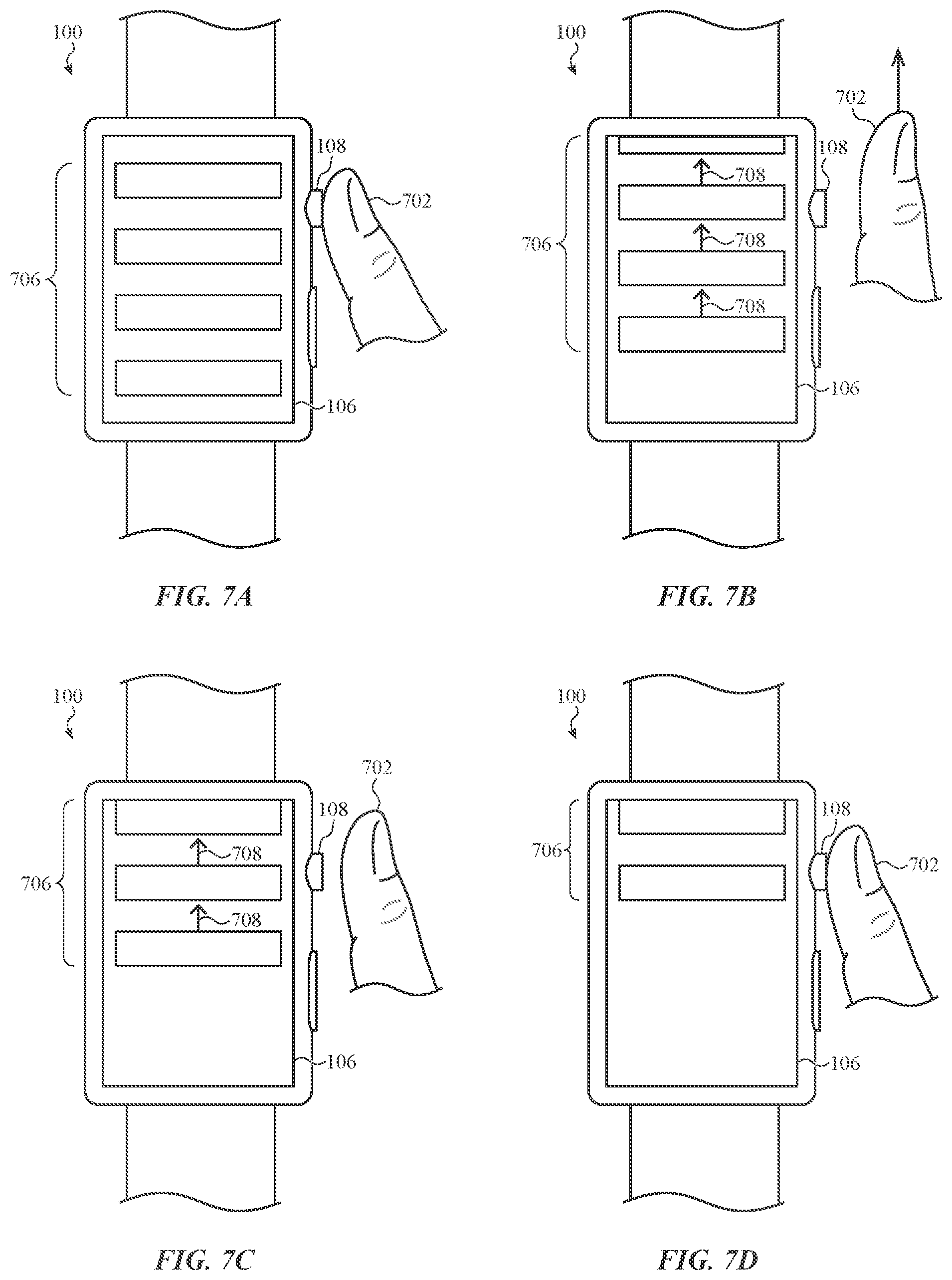
FIGS. 7A-7D depict a user-interface sequence in response to inputs to a contact-sensitive rotatable crown.
FIGS. 8A-8D depict another user-interface sequence in response to inputs to a contact-sensitive rotatable crown.
FIGS. 9A-9D depict yet another user-interface sequence in response to inputs to a contact-sensitive rotatable crown.
FIGS. 10A-10D depict yet another user-interface sequence in response to inputs to a contact-sensitive rotatable crown.
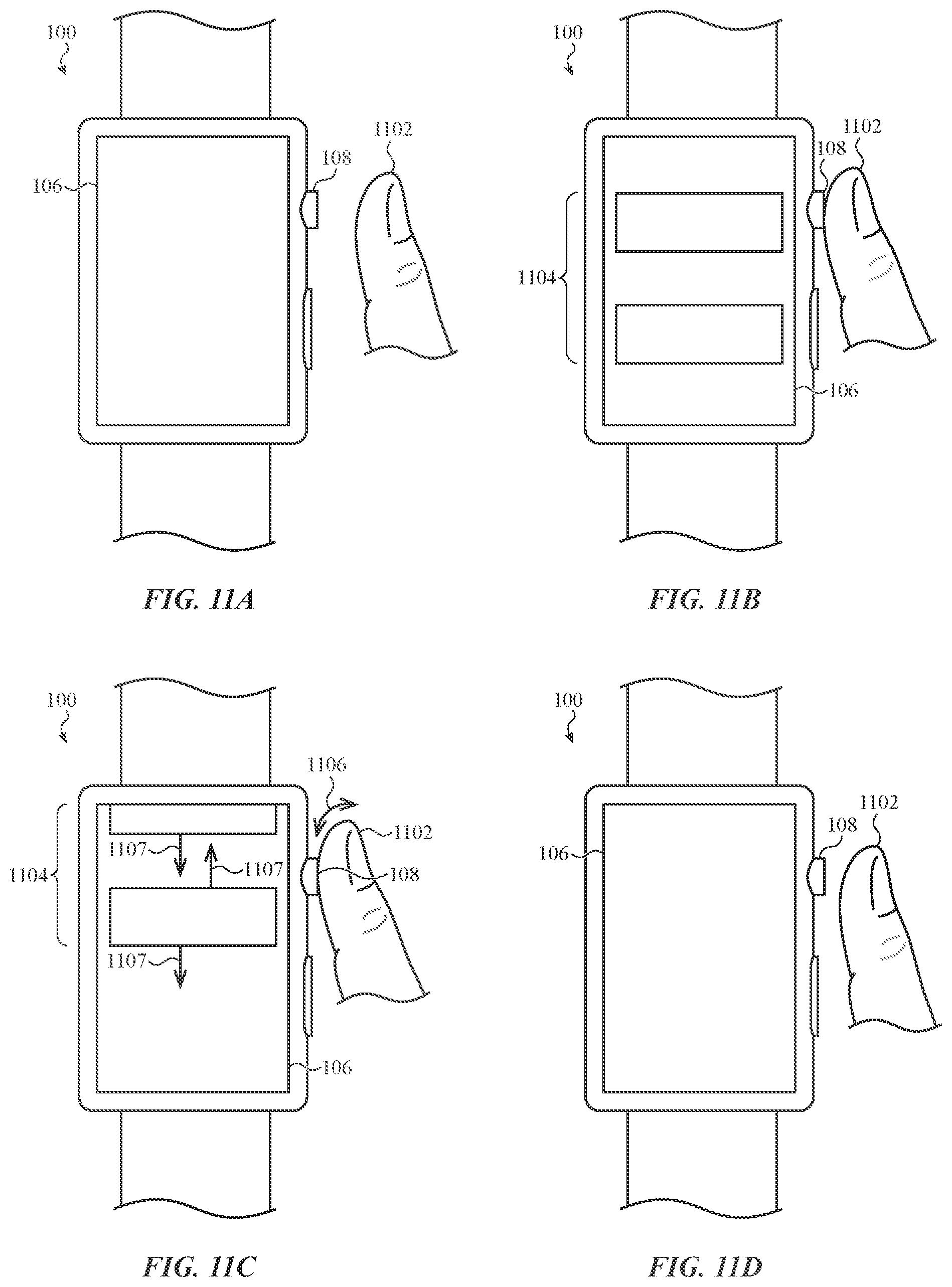
FIGS. 11A-11D depict yet another user-interface sequence in response to inputs to a contact-sensitive rotatable crown.
FIG. 12 depicts example components of an electronic device.
DETAILED DESCRIPTION
Reference will now be made in detail to representative embodiments illustrated in the accompanying drawings. It should be understood that the following description is not intended to limit the embodiments to one preferred embodiment. To the contrary, it is intended to cover alternatives, modifications, and equivalents as can be included within the spirit and scope of the described embodiments as defined by the appended claims.
The embodiments herein are generally directed to a crown of a wearable electronic device, such as a smart watch, and more particularly to a crown that includes contact-sensing functionality. For example, a crown of a wearable electronic device, such as a smart watch, may detect rotational movements (e.g., turning the crown), as well as translational movements (e.g., pushing or pulling the crown). These movements may be used to control various aspects of the electronic device, including manipulating a graphical output of a display. For example, a rotational movement of the crown may scroll a list that is shown on the display, or change the focus of a cursor or other indicator shown on the display. A translational movement of the crown, such as a push, may select displayed objects or activate certain device functions.
By adding contact-sensing functionality to a crown, the electronic device can determine to a greater degree of certainty whether any given rotational or translational motion is an intentional input or an accidental input. For example, a contact sensor may be configured to detect contact with the skin of a user, such as a user's fingertip. Because contact with objects or materials other than a user's skin are less likely to be intentional inputs, detecting contact between the crown and a user's skin may trigger or initiate a window for responding to rotational or translational movements of the crown. Within the window, the device may respond to rotational and/or translational movements (or lack thereof) of the crown because they are likely caused by direct interaction from a user. Outside the window (e.g., when no contact is detected), rotational and/or translational movements may be ignored as they are likely caused by accidental contact with the crown, such as by brushing the crown against a shirt sleeve or pocket.
By using a rotation tracking window as described herein, graphical outputs may be initiated and controlled with greater responsiveness and less lag and delay. For example, without contact-sensing functionality on the crown, an electronic device may ignore small movements of the crown so that accidental rotations or natural finger motion (which occur even when a user is attempting to keep the crown still) do not cause distracting or undesirable graphical outputs, scrolling, or user-interface activity. However, these techniques may result in a slower response to rotational inputs because a rotational input may be ignored until a certain threshold amount of rotation is satisfied. Thus there may be a period where a user is rotating the crown but the graphical output is not changing as expected. By using a contact sensor to establish a rotation tracking window, the electronic device may react more quickly to rotational inputs because any rotation detected within the window is more likely to be intentional. For example, scrolling of displayed items may appear to begin immediately upon rotation of the crown, rather than after a "dead band" or other rotational threshold is exceeded.
Further, the added contact-sensing functionality facilitates more intuitive and useful user interactions and user-interface functions. For example, a scroll animation that is initiated by a user rotating the crown can continue after the user's finger is removed from the crown, and then terminate when the user's finger is placed on the crown once again. Thus, the user can initiate a fast or continuing scroll by "flicking" the crown, and end the continuing scroll by touching the crown again. As another example, a display of the electronic device can be activated when a user places a finger on the crown, and deactivated when the user removes the finger, even if the user never rotates or translates (e.g., presses) the crown.
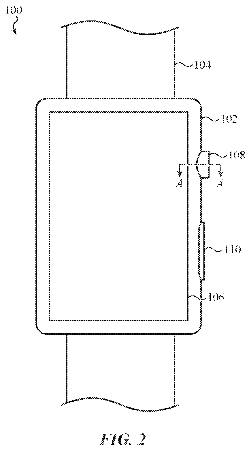
FIGS. 1 and 2 depict an electronic device 100. The electronic device 100 is depicted as a watch, though this is merely one example, and the concepts discussed herein may apply equally or by analogy to other electronic devices, including mobile phones (e.g., smartphones), tablet computers, notebook computers, head-mounted displays, digital media players (e.g., mp3 players), or the like.
The electronic device 100 includes a housing 102 and a band 104 coupled to the housing. The band 104 may be configured to attach the electronic device 100 to a user, such as to the user's arm or wrist.
The electronic device 100 also includes a display 106 coupled to the housing 102. The display 106 may define a front face of the electronic device 100. For example, in some cases, the display 106 defines substantially the entire front face and/or surface of the electronic device. The display 106 may be a touch- and/or force-sensitive display, and may include or be associated with any suitable touch or force sensing components, including capacitive sensors, resistive sensors, surface acoustic wave sensors, piezoelectric sensors, strain gauges, or the like. In conjunction with touch sensors, the display 106 may be configured to detect locations of touch events applied to the display 106, including locations of multiple simultaneous touches. In conjunction with force sensors, the display 106 may be configured to detect amounts or magnitudes of force associated with touch events applied to the display 106. The touch- and/or force-sensitive display may receive various types of user inputs to control or modify the operation of the device, including taps, swipes, multi-finger inputs, single- or multi-finger touch gestures, presses, and the like.
The electronic device 100 may also include other inputs, switches, buttons, or the like. For example, the electronic device 100 includes a button 110. The button 110 may be a movable button (as depicted) or a touch-sensitive region of the housing 102. The button 110 may control various aspects of the electronic device 100. For example, the button 110 may be used to select icons, items, or other objects displayed on the display 106, to activate or deactivate functions (e.g., to silence an alarm or alert), or the like.
The electronic device 100 also includes a crown 108 coupled to the housing 102. The crown 108 may afford a variety of potential user interactions. For example, the crown 108 may be rotatable about a rotation axis and relative to the housing 102 to accept rotational inputs. The crown 108 may also be translatable relative to the housing 102 to accept translational inputs. For example, the crown 108 may be movable along the rotation axis, towards and/or away from the housing 102. In particular, the crown 108 may be manipulated by pushing and/or pulling on the crown 108. As described herein, rotational and translational inputs may control various operations and user interfaces of the electronic device 100. In particular, inputs to the crown 108 may modify the graphical output of the display 106. For example, rotational movement of the crown 108 may zoom, scroll, or rotate a user interface or other object displayed on the display 106 (among other possible functions), while translational movements may select highlighted objects or icons, or activate or deactivate functions (among other possible functions).
The crown 108 may also be associated with or include a contact sensor that is configured to detect contact between a user and the crown 108 (e.g., touch inputs or touch events applied to the crown 108). The contact sensor may include or use any suitable type of sensor(s), including capacitive sensors, resistive sensors, magnetic sensors, inductive sensors, or the like. In some cases, the crown itself, or components of the crown, may be conductive and may define a conductive path between the user (e.g., the user's finger) and a contact sensor. For example, the crown may be formed from or include metal, and may be an electrode for conductively coupling a capacitive sensor to the user.
FIGS. 3A-3C are partial cross-sectional views of the electronic device 100, viewed along line A-A in FIG. 2. The cross-sectional views in FIGS. 3A-3C do not necessarily correspond to the exact structure of the electronic device 100 or any components thereof, and are instead intended as schematic views showing particular features of the crown 108 and in particular how the crown 108 may work with a contact sensor 302 to enable contact sensing via the crown 108.
As shown in FIG. 3A, the electronic device 100 includes a contact sensor 302 configured to detect a contact between the user and the crown. Information from the contact sensor 302 may be used to initiate a rotation tracking window, as described herein. This allows the electronic device 100 to act on rotational inputs immediately upon detecting rotation. For example, a graphical output can be controlled or changed as soon as rotation is detected along with contemporaneously detected contact between a user and the crown. This may reduce or eliminate the need for (or the effects of) dead bands, delays, or other filters that may be used where the crown 108 is not contact-sensitive.
As noted above, the contact sensor 302 may be any suitable type of contact sensor, and/or may rely on any suitable contact sensing technology. As shown, the contact sensor 302 is a capacitive contact sensor that detects touch events by detecting capacitive coupling between the crown 108 (or an electrode associated with the crown 108) and external objects.
The contact sensor 302 may be conductively coupled to the crown 108. As shown, the contact sensor 302 is in direct contact with the crown 108, though the contact sensor 302 may be conductively coupled to the crown via any suitable component or mechanism, including a rotary electrical contact such as a slip ring, brush (e.g., graphite brush), biased leaf spring, or the like. The crown 108 may be formed from or include conductive material to define a conductive path from an external surface of the crown 108 to the contact sensor 302. For example, the crown 108 may be formed from one or more pieces of metal (e.g., aluminum, stainless steel), graphite, carbon fiber, conductive ceramics, or the like. The crown may include non-conductive portions as well, including coatings, paints, caps, covers, or the like, so long as a conductive path exists between the contact sensor 302 and at least part of an exterior surface that is likely to be touched by a user when the user is manipulating the crown 108.
As shown in FIG. 3B, when a user's finger 300 (or other skin or body part) contacts the crown 108, a conductive path 304 is formed between the contact sensor 302 and the user's finger 300, thus capacitively coupling the user's finger 300 to the contact sensor 302. Where other types of contact sensors are used, such as inductive or resistive contact sensors, the capacitive coupling may be irrelevant or otherwise not used to sense touch events or contact with the user.
FIG. 3C shows another example of the crown 108 that includes electrodes 306 incorporated into the crown 108. The electrodes 306 may be conductively coupled to the contact sensor 302 via conductors 308 (or other conductive paths). The conductors 308 may be electrically isolated from the material of the crown 108 and from one another to provide isolated electrical paths from the electrodes 306 to the contact sensor 302. The contact sensor 302 may be configured to detect continuity between the electrodes, which may occur when a finger 300 contacts two or more electrodes 306. The contact sensor 302 may also or instead use multiple electrodes 306 to implement a mutual capacitance sensing scheme.
While FIG. 3C shows an example with two electrodes 306, more or fewer electrodes may be used. For example, in some cases, only a single electrode 306 is used. In such cases, the single electrode 306 may be the only component on the crown 108 that is conductively coupled to a contact sensor. In other cases, both the single electrode 306 and the crown itself 108 may be conductively coupled to the contact sensor. For example, a crown formed of conductive material may include a single electrode 306 and single conductor 308 that are electrically isolated from the material of the crown. The contact sensor 302 may be conductively coupled to the single conductor and the material of the crown. Accordingly, contact sensing schemes using two conductive paths (e.g., continuity, mutual capacitance) may be implemented using a conductive crown with only a single electrode 306.
FIG. 4 shows a partial cross-sectional view of an embodiment of an electronic device, such as the electronic device 100 (FIG. 1). The cross-sectional view in FIG. 4 corresponds to a view of an electronic device along line A-A in FIG. 2. FIG. 4 shows details of a crown 408 (which may correspond to the crown 108) and how the crown 408 may be structurally integrated with a housing 402 (which may correspond to the housing 102) as well as rotation, translation, and contact sensors. As described herein, integrating a contact sensor with a rotatable crown as shown in FIG. 4 allows the device to more definitively determine whether or not a rotational movement is intentional, which can produce faster and more precise responses to rotational inputs.
The crown 408 may include a knob 407 and a stem 400, with the stem 400 extending into the housing 402. The knob 407 and stem 400 may be a monolithic structure, including a single structure formed by machining, casting, molding, or otherwise forming a single piece of material into a crown 408 defining the knob 407 and stem 400. In other cases, the knob 407 and the stem 400 may be formed separately and attached to each other via adhesive, welding, mechanical fasteners, or the like. The crown 408 may also include other materials, components, coatings, or the like, which may or may not be conductive. For example, the stem 400 may be coated with an insulating material, a low-friction coating (e.g., polytetrafluoroethylene), or the like. Or a cap or disk may be placed on an exterior face 411 of the crown 408 (or positioned in an opening or recess in the exterior face 411). If any such components or materials are nonconductive, they may be integrated with the crown 408 so that a conductive path is formed between a contact sensor 409 and an interface surface or portion of the crown 408 (e.g., the portion that is usually or most likely contacted by a user when the user is manipulating the crown 408 to provide inputs to the device).
The crown 408 may be coupled to the housing 402 such that the crown 408 can translate and rotate relative to the housing 402. Rotational movements may be about a rotation axis, as indicated by arrow 414, while translational movements may be along the rotation axis, as indicated by arrow 412. To facilitate these movements, the electronic device may include one or more interface components 416 between the crown 408 (e.g., the stem 400) and the housing 402. The interface components 416 may be any suitable material or component, including an O-ring formed from or including rubber, elastomer, silicone, or any other suitable material. The interface components 416 may slide, deform, or translate relative to the housing 402 and the crown 408, thus allowing the crown 408 to move relative to the housing 402. The interface components 416 may also maintain a seal between the stem 400 and the housing 402 during rotation and translation of the crown 408.
The electronic device includes sensors for detecting rotational and/or translational movement of the crown 408. For example, a rotation sensor 406 may detect rotational movement of the crown 408, while a switch 404 may detect translational movement. The switch 404 may be a collapsible dome or any other suitable switch that can detect translational movement. Where the switch 404 is a collapsible dome, the dome may provide a tactile response to the crown 408 as well as a biasing or return force that forces the crown 408 towards an unactuated (e.g., rest) state.
The rotation sensor 406 may be any suitable type of rotation sensor, including an optical sensor, an encoder, a hall-effect sensor, a resolver, or any other suitable sensor that can detect rotational movements of the crown 408. In some cases, the stem 400 (or another portion or component of the crown 408) may include features to assist in rotation tracking. For example, the stem 400 may have grooves, teeth, or optical features (e.g., a printed pattern) that an optical sensor can detect. In some cases, the rotation sensor 406 detects defects in the surface finish of the stem 400, including scratches, indentations, or other irregular features that do not adhere to a regular or periodic pattern.
The rotation sensor 406 may provide various information about rotational movements of the crown 408, including speed of rotation, direction of rotation, acceleration of rotation, and the like. Such information may be used to control the operation of an electronic device in various ways. For example, a graphical output of a display (e.g., the display 106) may be responsive to rotational inputs from the crown. As one example, a rotational input may cause a list of items that is being displayed on a display (e.g., the display 106) to scroll across the display at a speed and/or direction dictated by a speed and/or direction of rotation of the crown 408. As another example, a zoom level of a graphical user interface, image, or other displayed object may be controlled by rotating the crown 408. The zoom or magnification level may change based on the speed and/or direction of rotation of the crown. Rotational inputs may be used to control other aspects of a device in addition to or instead of those examples provided. Further, as noted herein, rotational inputs detected by the rotation sensor 406 may control the graphical output of the device only when a contemporaneous touch event is detected on the crown 408 via the contact sensor 409.
The contact sensor 409 may be any suitable contact sensor. In some cases, the contact sensor 409 is a capacitive sensor that is conductively coupled to the crown 408. Other types of contact sensors may also be used, including resistive sensors, magnetic sensors, inductive sensors, or the like. The crown 408 may be conductively coupled to the contact sensor 409 via a conductor. Because the crown 408 is rotatable, the contact sensor 409 may be conductively coupled to the crown 408 (e.g., the stem 400 of the crown 408) via an electrical connector that allows the crown 408 to rotate. For example, a slip ring, brush (e.g., a graphite brush), biased leaf spring, or any other suitable rotary electrical contact or connection technique, may conductively couple the contact sensor 409 to the stem 400. As shown in FIG. 4, the contact sensor 409 is adjacent the stem 400, though this is merely for illustration. In other cases, the crown 408 may be conductively coupled to a contact sensor 409 that is located elsewhere within the housing 402.
As noted above, some types of sensors, such as capacitive sensors, rely on a conductive path between the sensor and a sensed object in order to detect touch events. In order to isolate contact-sensitivity to the crown 408, the crown 408 may need to be electrically isolated from other conductive components of the electronic device (e.g., the housing 402). Accordingly, in some cases, the interface components 416 may electrically isolate the crown 408 from the housing 402. For example, the interface components 416 may be formed from dielectric or nonconductive material (e.g., rubber, silicone, ceramic, plastic), thus preventing a conductive path between the crown 408 and the housing 402 under normal use conditions, and isolating the contact sensing functionality to the crown 408 itself. If the crown 408 was not electrically isolated from the housing 402, the contact sensor 409 may be unable to distinguish between touch events on the housing 402 and touch events on the crown 408, which may reduce the effectiveness of such inputs.
FIG. 5 shows a partial cross-sectional view of an embodiment of an electronic device, such as the electronic device 100 (FIG. 1). The cross-sectional view in FIG. 5 corresponds to a view of an electronic device along line A-A in FIG. 2. FIG. 5 shows details of a non-movable crown 508 (which may correspond to the crown 108) and how the crown 508 may be structurally integrated with a housing 502 (which may correspond to the housing 102) and a contact sensor 509. As noted, the crown 508 is fixed in position relative to the housing 502, and thus does not rotate or translate relative to the housing 502. Rather, user inputs such as presses and swipes (e.g., a user sliding a finger over the peripheral rim of the crown 508) may be detected by force sensors, optical sensors, or any other suitable type of sensor.
The contact sensor 509 may be a capacitive sensor (or any other suitable sensor), and may be conductively coupled to the crown 508 in any suitable way, as described above with respect to the crown 408. Despite being fixed to the housing 502, the crown 508 may be electrically isolated from the housing 502 to isolate the contact sensing functionality to the crown 508. For example, a dielectric or nonconductive material 504 may be disposed between the crown 508 and the housing 502. The material 504 may be any suitable material, including plastic, rubber, silicone, adhesive, epoxy, ceramic, or the like.
FIG. 6 depicts an example process 600 for operating a wearable electronic device, such as the electronic device 100 (FIGS. 1 and 2), or any other suitable wearable electronic device. The wearable electronic device may have a display (e.g., the display 106) and a crown configured to receive rotational or dial-based input (e.g., the crown 108), as described above. The process 600 may be implemented as processor-executable instructions that are stored within memory of the wearable electronic device. The process 600 leverages the contact-sensitivity of the crown to determine when to respond to rotational movement of the crown (e.g., when to modify a graphical output of the display based on the rotational movement), and when to ignore rotational movement. The process 600 may also use the contact-sensitivity of the crown to trigger discrete user-interactions, such as activating and deactivating a display.
In operation 602, a rotation-tracking mode is initiated based on a detection of a contact between a user and the rotatable crown. Detecting the contact between the user and the rotatable crown may include detecting an electrical characteristic of the rotatable crown that is indicative of contact between a user and the rotatable crown. The electrical characteristic may be, for example, a capacitance, a resistance, or the like, and may be measured by a contact sensor within the electronic device (e.g., a capacitive sensor that is conductively coupled to the crown).
Detecting contact between a user and the rotatable crown (e.g., via a capacitive sensor) indicates that a user likely has a finger or hand on the rotatable crown, and thus that any motion of the crown (such as rotational or translational motions) are likely intentional inputs to the crown. Accordingly, at operation 604, in response to initiating the rotation-tracking mode, the electronic device may control a graphical output of the display in accordance with rotational movement or absence of rotational movement of the rotatable crown as detected by a rotation sensor (e.g., the rotation sensor 406) associated with the crown. Controlling the graphical output of the display in accordance with rotational movement or absence of rotational movement of the rotatable crown may be referred to as controlling the graphical output of the display in accordance with a first user-interface control scheme. Controlling the graphical output may include moving (e.g., scrolling) an element or item displayed on the display, or zooming in or out on an image, user interface, or other content displayed on the display. Yet another example of controlling the graphical output may include changing a color or other visible property (e.g., shape, size, saturation, contrast) of a displayed element or item. Other ways of controlling and/or modifying a graphical output are also contemplated.
By waiting until a rotation-tracking mode is initiated before controlling the graphical output of the display in accordance with rotational movement of the rotatable crown, may facilitate more responsive graphical outputs. For example, as noted above, the detection of a contact between the user and the crown indicates that the user is intentionally touching the crown. As a result, the electronic device may react immediately or more quickly to signals from a rotation sensor, because any rotation that is contemporaneous with a touch input is likely an intentional rotation. In some cases, using a contact-triggered rotation tracking mode may reduce or eliminate the need for heuristics to guess whether a detected rotation is likely intentional. Such heuristics may include timers, delays, or filters, all of which may introduce delay and lag between rotation of crown and modification of the graphical output.
One particular example of controlling the graphical output of the display in accordance with rotational movement of the rotatable crown (e.g., according to the first user-interface control scheme) may include causing a list of items to scroll across the display in accordance with a direction of rotation of the rotatable crown. For example, if a list of items such as words (e.g., names, contacts), images (e.g., thumbnails, photographs), icons, or the like, is displayed on the display, the rotational movement of the crown may cause the list of items to scroll. Controlling the graphical output of the display in accordance with rotational movement of the rotatable crown may also or instead include causing the list of items to scroll across the display in accordance with a speed of rotation of the rotatable crown. Controlling the graphical output of the display in accordance with rotational movement or absence of rotational movement of the rotatable crown (e.g., according to the first user-interface control scheme) may include causing the list of items to remain stationary when no rotation is detected. Examples of scrolling (or not scrolling) a list of items during a rotation-tracking mode are described herein with reference to FIGS. 7A-8D.
At operation 606, the rotation-tracking mode is terminated based on a termination of the contact between the user and the rotatable crown (e.g., when the user lifts his or her finger off of the crown). For example, a contact sensor may detect a change or end of the electrical characteristic (e.g., a capacitance, resistance, etc.) that is indicative of contact between the user and the rotatable crown. Terminating the rotation-tracking mode may correspond to the electronic device simply ignoring further signals, or lack thereof, from the rotation sensor (e.g., encoder). In some cases, the rotation sensor may be deactivated, turned off, or placed in a low-power mode when the rotation-tracking mode is not active (e.g., after the rotation-tracking mode is terminated). In other cases, the rotation sensor may remain in a normal operating mode, and any signals or other data or signals indicative of rotation or lack of rotation of the crown may be ignored (e.g., they might not be used to control a graphical output of the device).
At operation 608, in response to terminating the rotation-tracking mode, the graphical output of the display is controlled without regard to rotational movement or absence of rotational movement of the rotatable crown. Controlling the graphical output of the display without regard to rotational movement or absence of rotational movement of the rotatable crown may be referred to as controlling the graphical output of the display in accordance with a second user-interface control scheme.
In some cases, controlling the graphical output without regard to rotational movement or absence of rotational movement (e.g., according to the second user-interface control scheme) includes causing the graphical output to move or provide a simulation or appearance of motion even if there is no rotational motion detected by a rotation sensor. In other cases, controlling the graphical output without regard to rotational movement or absence of rotational movement includes causing the graphical output to not move (e.g., maintaining a stationary display) even if rotational motion is detected by the rotation sensor. Thus, in some implementations, detecting contact between a user and the rotatable crown may be a logical or programmatic condition precedent to modifying a graphical output based on a state of the rotation sensor, such as speed and/or direction of motion, if any. Examples of controlling the graphical output without regard to rotational movement or absence of rotational movement are described herein with respect to FIGS. 7A-10D.
In some cases, controlling the graphical output of the display without regard to rotational movement or absence of rotational movement of the rotatable crown includes causing a list of items to scroll across the display in a previously detected direction of rotation of the rotatable crown. For example, if a user is scrolling through a list of items by rotating the crown, and then quickly releases the crown (e.g., "flicking" the crown), the list may continue to scroll despite the crown no longer being rotated (or if the crown is rotated but there is no corresponding detection of a touch event on the crown). In this way, a user can rapidly scroll through a list without having to continue to turn the rotatable crown to cause the list to scroll.
Whether or not a list of items continues to scroll across the display in a previously detected direction may depend, at least in part, on a speed or acceleration of rotation immediately prior to detecting the termination of the contact between the user and the crown. For example, if the user is scrolling below a speed or acceleration threshold, detecting that a user's finger has been removed from the crown may cause the list to cease scrolling entirely. If the user is scrolling above the speed or acceleration threshold, detecting that the user's finger has been removed may cause the list to continue to scroll. This may provide an intuitive user interface technique, as a rapid rate or acceleration of scrolling followed by a removal of a finger (or fingers) may correspond to a user "flicking" the rotatable crown. A user may expect that this type of input will result in the fastest possible scrolling speed, and thus may naturally attempt this input even without a hint or other instruction. On the other hand, when a user is scrolling a list slowly, it may indicate that they are reading or viewing items in the list while the list is moving. Accordingly, the user may naturally expect the list to cease scrolling when they take their finger(s) off of the crown. This process thus produces a natural, intuitive user experience.
The speed or acceleration threshold may be determined by, based on, or otherwise correlate to a readability of the items being scrolled. For example, a speed at which scrolled items can be clearly read may be determined experimentally (or via any other analysis or calculation). The threshold may then be set at or below that speed. Accordingly, when the list items are readable when scrolling, releasing the crown will end the movement of the list, and when the list items are not readable when scrolling, movement of the list will continue after the crown is released.
When the list of items is scrolled after release of the crown, the initial scroll speed of the list may be substantially the same as the speed that was indicated by the rotation of the crown. In some cases, the scroll speed may decrease with time (e.g., decay) after the rotation-tracking window is terminated. For example, after the device detects removal of the user's finger(s), the list of items may continue to scroll, but the scroll speed may decrease for a period of time until the list becomes stationary. The period of time that the list continues to scroll may be any suitable duration. For example, in some cases it may be determined by a timer, so that the list continues to scroll for 1 second, 2 seconds, 3 seconds, 4 seconds, or any other suitable duration. In some cases, the duration may be determined at least in part by a speed of rotation or scrolling immediately prior to the user releasing the crown. For example, a faster scroll or rotation speed may result in a longer scrolling duration after release of the crown, while a slower scroll or rotation speed may result in a shorter scrolling duration after release of the crown.
Once a list of items is scrolling after removal of a user's finger(s), such as while the list of items is scrolling due to a "flick" input on the rotatable crown, the user may wish to terminate the scroll. Accordingly, certain inputs or other events may result in termination of the scroll, such as a user touching the crown with or without rotating the crown. For example, while the list of items is scrolling across the display the electronic device may initiate a subsequent rotation-tracking mode based on a detection of a subsequent contact between the user and the rotatable crown. That is, when the electronic device detects a touch event on the crown while the list of items is scrolling, the device may once again begin using the rotational movement to drive device operations. During the subsequent rotation-tracking mode, the electronic device may determine if a speed of rotation of the rotatable crown is below a threshold value. In accordance with a determination that the speed of rotation of the rotatable crown is below the threshold value, for example if the crown is not being rotated at all or is only being rotated a negligible amount, the electronic device may cease scrolling the list of items across the display. Accordingly, a user can end an automatic or continuing scroll simply by placing a finger on the crown. The list of items may be stopped (e.g., if the crown is touched but not rotated), or it may be scrolled in accordance with a new rotational input (e.g., if the crown is touched and rotated to initiate a new scroll). A graphical example of scrolling a list of items (or any other object or user interface components) in accordance with the foregoing process is described with respect to FIGS. 7A-7D.
The foregoing example relates to scrolling a list of items. The list of items may be lists or groups of icons (e.g., graphics corresponding to applications that are executable on the electronic device), words (e.g., names in a user's contact list, titles of posts in a social network, emails or portions thereof, documents, webpages), images (e.g., photographs, thumbnails), or any other items. However, the same process may apply to other graphical displays or user interface manipulations. For example, rotational movements may be used to zoom in and out of displayed images, interfaces, documents, webpages, or the like. Such zooming interactions may be controlled in the same or similar manner as described above. For example, a "flick" of the rotatable crown may produce a continuing zoom (in or out) of a graphical display, and a subsequent touch on the rotatable crown (with or without rotation) may terminate the zoom.
Another example operation that includes controlling the graphical output of the display without regard to rotational movement or absence of rotational movement of the rotatable crown includes causing the list of items to scroll across the display in a direction opposite to a previously detected direction of rotation of the rotatable crown. This type of operation may be used when a user has scrolled to the end of a list. For example, when a user scrolls to the end of a list of items, the list may be scrolled past a final scroll position (e.g., where the last item in a list is at the bottom of a display). This may be an undesirable graphical state, as the user may lose the context of the list entirely. Accordingly, if a list is scrolled past a final scroll position and then the crown is released, the list may scroll in a direction opposite the prior scroll direction to return to the final scroll position. A graphical example of returning a list to a final scroll position by scrolling a list of items (or any other object or user interface components) in a direction opposite a prior scroll direction is described with respect to FIGS. 8A-8D.
FIGS. 7A-7D illustrate an example interaction between the electronic device 100 and a user (e.g., a user's finger 702). In particular, FIGS. 7A-7D show how a user interface may react to a "flick" input on a crown, as described above. As shown in FIG. 7A, the electronic device 100 is displaying a list of items 706 on the display 106. The items in the list may include words, objects, icons, images, or any other suitable displayable item, as described above. Moreover, while the list of items 706 is shown as a group of rectangles, this is merely an example illustration, and the list of items may take any other suitable form or appearance.
A finger 702 rotates the crown 108 in a direction that causes the list of items 706 to scroll in a first direction, followed by removal of the finger 702 from the crown 108, as illustrated by the sequence from FIG. 7A to FIG. 7B. The rotation of the crown 108 causes the list of items to scroll in a direction, as indicated by arrows 708.
As long as the finger 702 is in contact with the crown 108, the electronic device 100 may be in a rotation-tracking mode in which the list of items 706 is scrolled or not scrolled based on the presence or absence of rotational motion of the crown 108. For example, the rotational motion of the crown 108 that is detected while the finger 702 is in contact with the crown 108 causes the list of items 706 to scroll.
If the speed (or acceleration) of the rotation of the crown 108 satisfies an optional threshold, as described above, the list of items 706 may continue to scroll in the same direction (as indicated by arrows 708) even after the finger 702 has been removed from the crown 108. Once a contact sensor determines that the finger 702 is no longer in contact with the crown 108, the electronic device 100 terminates the rotation-tracking mode and begins to control the graphical output of the display without regard to rotational movement or absence of rotational movement of the crown 108. For example, FIG. 7C shows the list of items 706 continuing to scroll even though the user's finger 702 is no longer contacting the crown 108.
In particular, even though the crown 108 may no longer be rotating (or even if it is rotating due to inertia after removal of the finger 702), the electronic device 100 may control how and whether the list of items 706 scrolls without regard to the rotation or lack of rotation of the crown. In this way, the electronic device 100 uses the additional contact sensitivity of the crown 108 to determine when and whether to use the rotational status of the crown 108 to control or modify the graphical output of the device 100.
If the user's finger 702 touches the crown 108 while the list of items 706 is still moving, as illustrated in the sequence from FIG. 7C to FIG. 7D, the electronic device 100 may reinitiate the rotation-tracking mode and once again begin scrolling or not scrolling the list of items 706 based the rotation or lack of rotation of the crown 108. In particular, as shown in FIG. 7D, the list of items 706 may cease scrolling when the finger 702 is determined to be in contact with the crown 108 (e.g., when a touch event is detected) without accompanying rotation of the crown 108. Alternatively, as noted above, if the finger 702 touching the crown 108 is accompanied by a rotation of the crown 108, the list of items 706 may scroll across the display according to a speed and/or direction of the accompanying rotation. FIG. 7D shows a static (e.g., not scrolling) list of items 706 after a contact sensor associated with the crown 108 detected a touch event without concurrent rotation or with only incidental or nominal rotation of the crown 108.
FIGS. 8A-8D illustrate another example interaction between the electronic device 100 and a user (e.g., a user's finger 802). In particular, FIGS. 8A-8D show how a user interface may react to a rotational motion that causes a list to scroll past a final scroll position, as described above. As shown in FIG. 8A, the electronic device 100 is displaying a list of items 804 on the display 106. The items in the list may include words, objects, icons, images, or any other suitable displayable item, as described above. Moreover, while the list of items 804 is shown as a group of rectangles, this is merely an example illustration and the list of items may take any other suitable form or appearance.
A finger 802 rotates the crown 108, as indicated by arrow 805, in a direction that causes the list of items 804 to scroll in a first direction, as indicated by arrows 808. In particular, the electronic device 100 may detect that the finger 802 has contacted the crown 108, and in response initiate a rotation-tracking mode. While the rotation-tracking mode is active, the list of items 804 may be moved in accordance with rotational movement, or absence of rotational movement, of the crown 108. For example, if the crown 108 is rotated, the list of items 804 will move in a speed and/or direction corresponding to the rotational movement. Similarly, if the crown 108 is stationary (e.g., because the user is touching but not rotating the crown 108), the list of items 804 may remain in a static position.
As shown in FIG. 8B, the finger 802 may cease rotating the crown 108 after the list of items 804 has scrolled past a final scroll position, resulting in the list of items 804 ceasing to scroll. As noted above, a final scroll position for a list of items 804 may be a position where a last item in the list of items 804 is positioned at or near a bottom of the display 106. For example, FIGS. 8A and 8D may illustrate the list of items 804 in a final scroll position. In some cases, once the list of items 804 reaches a maximum scroll position, the list of items 804 ceases to scroll despite further rotational movement of the crown. A maximum scroll position may correspond to a position where only one list item is showing on the display 106, or where a predetermined blank space is shown below the last list item.
The list of items 804 may remain in the scrolled position shown in FIG. 8B (which is past a final scroll position and may or may not be at a maximum scroll position) as long as the finger 802 remains in contact with the crown 108, as detected by a contact sensor associated with the crown 108. This operation is consistent with the electronic device 100 operating in a rotation-tracking mode and thus controlling the graphical output of the display 106 in accordance with rotational movement or absence of rotational movement of the rotatable crown. More particularly, the electronic device 100 is detecting an absence of rotational movement while also detecting contact between the user's finger 802 and the crown 108, and thus is controlling the graphical output of the display 106 by not moving the list of items 804. If no contact sensing capability were provided, the electronic device 100 may be unable to determine whether the lack of rotational movement of the rotatable crown is due to the user continuing to hold the crown in a particular position, or due to the user having removed their finger from the crown. Accordingly, by incorporating contact sensing into the crown 108, such ambiguity can be eliminated or reduced and a more natural user experience may be provided.
FIG. 8C shows how the graphical output may be controlled once the user's finger 802 is removed from the crown 108. In particular, once the user's finger 802 is removed from the crown 108, the rotation-tracking mode may be terminated, and the graphical output of the display 106 may be controlled without regard to rotational movement or absence of rotational movement. In the illustrated example, the list of items 804 that was previously being held in a position away from a final scroll position (e.g., a maximum scroll position) due to the continued presence of the finger 802 on the crown 108, may move to the final scroll position once the finger 802 is removed, as shown in FIG. 8D. Thus, because the rotation-tracking mode has been terminated the list of items 804 is moved despite there being no corresponding rotation of the crown 108.
Moving to the final scroll position may include scrolling the list of items 804 in a direction that is opposite the previous direction of movement. For example, as shown in FIGS. 8A-8B, the list of items 804 may be scrolled in a first direction in response to rotational movement of the crown 108, as indicated by arrows 808. When the user's finger 802 is released, the list of items 804 may be scrolled in a second direction opposite the first direction, as indicated by arrows 810 (FIG. 8C).
FIGS. 8A-8D show how a list of items may be moved away from and subsequently return to a final scroll position based on a rotation of and subsequent release of the rotatable crown. Final positions or arrangements of displayed objects other than that illustrated in FIGS. 8A-8D are also possible. For example, a final scroll position of a list of items may correspond to any arrangement of objects that visually indicates or suggests an end of the list of items, and may be a position from which further scrolling may be limited in one or more directions. Moreover, while a final scroll position is shown at a bottom or end of a list of items, there may also be a final scroll position at the top or beginning of the list. Similar graphical operations may apply at any final scroll position.
FIGS. 7A-8D show example graphical outputs relating to lists of items. The techniques described herein, and in particular using a contact sensor to enable a rotation-tracking mode, may also be used for other types of graphical outputs. FIGS. 9A-10D show example interactions in which an image zoom or magnification level is controlled by a rotatable crown associated with a contact sensor.
As shown in the sequence from FIG. 9A to FIG. 9B, a finger 902 rotates the crown 108 in a direction that causes an image 904 to zoom in a first direction (e.g., magnifying the image or "zooming in"), followed by removal of the finger 902 from the crown 108. Similar to the operations described above with respect to FIGS. 7A-7B, as long as the finger 902 is in contact with the crown 108, the electronic device 100 may be in a rotation-tracking mode in which the image 904 is magnified or not magnified based on the presence or absence of rotational motion of the crown 108.
If the speed of the rotation of the crown 108 satisfies an optional threshold, the image 904 may continue to zoom in the same direction even after the finger 902 has been removed from the crown 108. Once a contact sensor determines that the finger 902 is no longer in contact with the crown 108, and optionally after the speed satisfies the threshold, the electronic device 100 terminates the rotation-tracking mode and begins to control the graphical output of the display without regard to rotational movement or absence of rotational movement of the crown 108. For example, FIG. 9C shows the image 904 continuing to be expanded even though the user's finger 902 is no longer contacting the crown 108.
If the user's finger 902 touches the crown 108 while the image 904 is still expanding, as illustrated in the sequence from FIG. 9C to FIG. 9D, the electronic device 100 may reinitiate the rotation-tracking mode and once again begin magnifying or not magnifying the image 904 based the rotation or lack of rotation of the crown 108. In particular, as shown in FIG. 9D, the image 904 may cease zooming when the finger 902 is determined to be in contact with the crown 108 (e.g., when a touch event is detected) without accompanying rotation of the crown 108.
FIGS. 10A-10D illustrate another example interaction between the electronic device 100 and a user (e.g., a user's finger 1002). In particular, FIGS. 10A-10D show how a user interface may react to a rotational motion that causes an image to be magnified or expanded past a maximum magnification.
As shown in FIG. 10A, the electronic device 100 is displaying an image 1004 on the display 106. A finger 1002 rotates the crown 108, as indicated by arrow 1006, in a direction that causes the image 1004 to be magnified. In particular, the electronic device 100 may detect that the finger 1002 has contacted the crown 108 and initiate a rotation-tracking mode. While the rotation-tracking mode is active, the image 1004 may be magnified or reduced in accordance with rotational movement, or absence of rotational movement, of the crown 108.
As shown in FIG. 10B, the finger 1002 may cease rotating the crown 108 after the image 1004 has been magnified past a final magnification, resulting in the image 1004 ceasing to be further magnified. The final magnification may be determined in any suitable way and based on any available data or information, including an image size, an image resolution, a display size, a user-selected value, an image content, an image file or data type, or the like. As one example, the final magnification may correspond to a multiple of the display size, such as when the whole of the magnified image would be 500% of the size of the display 106 (or any other suitable m
References
-
sooperarticles.com/health-fitness-articles/children-health-articles/how-vesag-helps-kids-women-visitors-218542.html
-
mhealth.vesag.com/?m=201012
-
virtualpressoffice.com/eventsSubmenu.do?page=exhibitorPage&showId=1551&companyId=5394
-
amazon.com/iPhone-Universal-Remote-Control-Accessory/dp/tech-data/B0038Z4
-
vyasa-kaaranam-ketkadey.blogspot.com/2011/03/vesag-wrist-watch-for-dementia-care.html
-
-
24-7pressrelease.com/press-release/vyzin-unveiled-personal-emergency-response-system-pers-with-remote-health-monitoring-that-can-be-used-for-entire-family-219317.php
-
deskthority.net/keyboards-f2/optical-switch-keyboards-t1474.html
-
whatafuture.com/2014/02/28/google-smartwatch/#sthash.Yk35cDXK.dpbs
-
ip.com
-
medicineandtechnology.com/2010/08/2010-mhealth-summit-emerges-as-major.html
-
sensetekgroup.com/2010/11/29/wireless-health-monitoring-system
-
ezinearticles.com/?How-Vesag-Helps-People-Who-Want-to-Be-There?&id-5423873
-
itnewsafrica.com/2010/11/mobile-innovation-helps-dementia-andalzheimer%E2%80%99s-patients
D00000
D00001
D00002
D00003
D00004
D00005
D00006
D00007
D00008
D00009
D00010
D00011
D00012
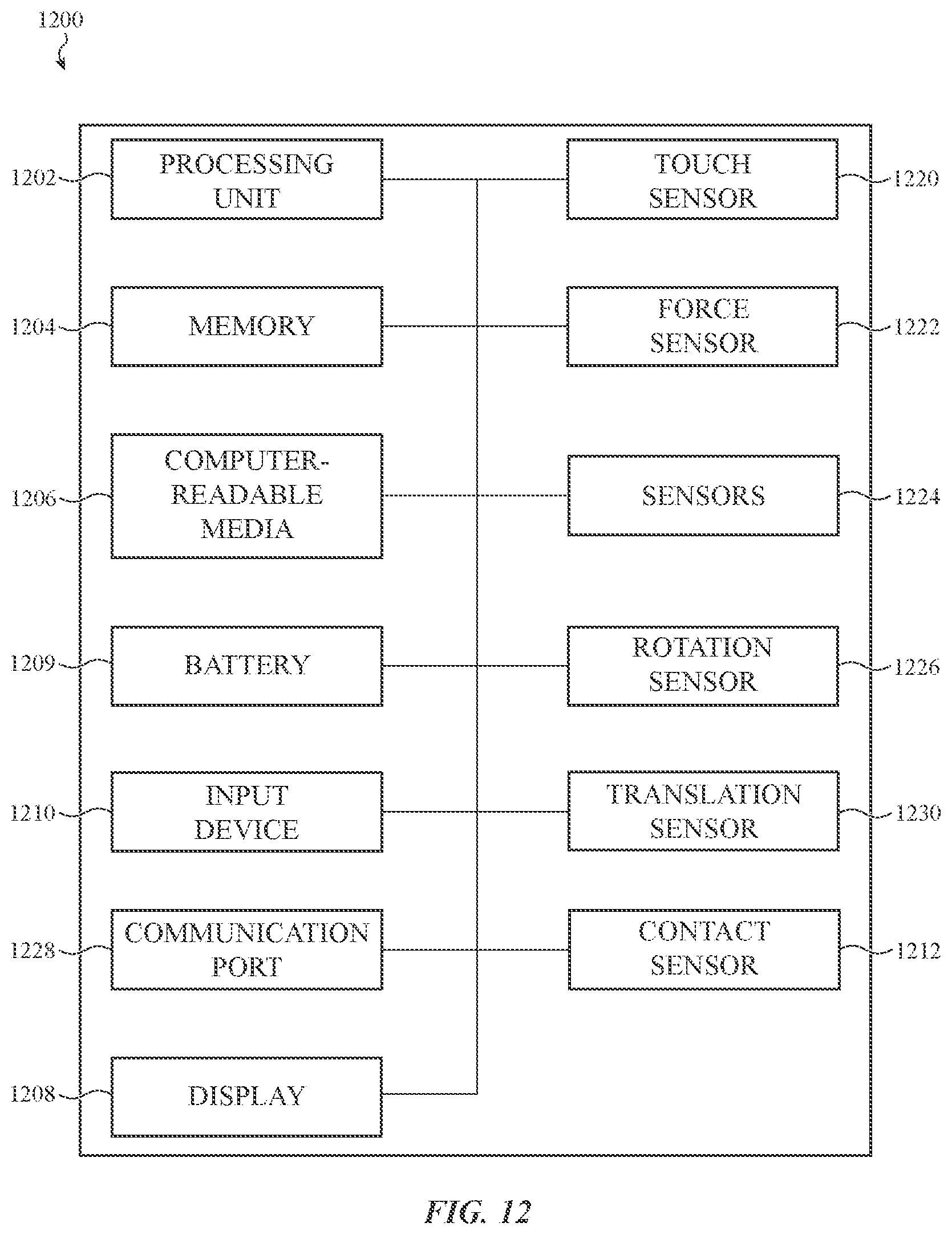
XML
uspto.report is an independent third-party trademark research tool that is not affiliated, endorsed, or sponsored by the United States Patent and Trademark Office (USPTO) or any other governmental organization. The information provided by uspto.report is based on publicly available data at the time of writing and is intended for informational purposes only.
While we strive to provide accurate and up-to-date information, we do not guarantee the accuracy, completeness, reliability, or suitability of the information displayed on this site. The use of this site is at your own risk. Any reliance you place on such information is therefore strictly at your own risk.
All official trademark data, including owner information, should be verified by visiting the official USPTO website at www.uspto.gov. This site is not intended to replace professional legal advice and should not be used as a substitute for consulting with a legal professional who is knowledgeable about trademark law.