Exterior rearview mirror with turn signal unit
Juris , et al.
U.S. patent number 10,661,705 [Application Number 16/240,116] was granted by the patent office on 2020-05-26 for exterior rearview mirror with turn signal unit. This patent grant is currently assigned to MAGNA MIRRORS HOLDING GMBH. The grantee listed for this patent is Magna Mirrors Holding GmbH. Invention is credited to Peter Juris, Mark Kennedy.


| United States Patent | 10,661,705 |
| Juris , et al. | May 26, 2020 |
Exterior rearview mirror with turn signal unit
Abstract
An exterior rearview mirror assembly for a vehicle includes a turn signal unit having a housing, a light source and a lens disposed in front of the light source and attached at the housing. The turn signal unit includes an aperture element disposed between the light source and the lens, and includes a film disposed between the lens and the housing so as to be in front of the light source. With the exterior rearview mirror assembly disposed at a side of the vehicle, light emitted by the light source, when powered, passes through the film and through an aperture of the aperture element and through the lens in the forward direction of travel of the equipped vehicle. The film includes structured sections such that light emitted by the light source, when powered, passes through the structured sections of the film and forms an illuminated logo.
| Inventors: | Juris; Peter (Vahom, SK), Kennedy; Mark (Aschaffenburg, DE) | ||||||||||
|---|---|---|---|---|---|---|---|---|---|---|---|
| Applicant: |
|
||||||||||
| Assignee: | MAGNA MIRRORS HOLDING GMBH
(Sailauf, DE) |
||||||||||
| Family ID: | 60676537 | ||||||||||
| Appl. No.: | 16/240,116 | ||||||||||
| Filed: | January 4, 2019 |
Prior Publication Data
| Document Identifier | Publication Date | |
|---|---|---|
| US 20190135168 A1 | May 9, 2019 | |
Related U.S. Patent Documents
| Application Number | Filing Date | Patent Number | Issue Date | ||
|---|---|---|---|---|---|
| 15642750 | Jul 6, 2017 | 10173581 | |||
Foreign Application Priority Data
| Jul 8, 2016 [DE] | 10 2016 212 527 | |||
| Current U.S. Class: | 1/1 |
| Current CPC Class: | F21S 43/245 (20180101); B60Q 1/28 (20130101); F21S 43/247 (20180101); F21V 17/162 (20130101); F21S 43/27 (20180101); F21S 43/237 (20180101); F21S 43/255 (20180101); F21S 43/26 (20180101); B60Q 1/2665 (20130101); B60Q 1/34 (20130101); B60R 1/1207 (20130101); B60R 1/06 (20130101); F21W 2103/20 (20180101); B60R 13/005 (20130101) |
| Current International Class: | F21V 5/00 (20180101); F21S 43/247 (20180101); B60Q 1/26 (20060101); F21S 43/20 (20180101); F21S 43/27 (20180101); F21V 17/16 (20060101); B60R 1/12 (20060101); B60Q 1/34 (20060101); B60Q 1/28 (20060101); F21S 43/245 (20180101); F21S 43/237 (20180101); B60R 1/06 (20060101); B60R 13/00 (20060101) |
References Cited [Referenced By]
U.S. Patent Documents
| 4041301 | August 1977 | Pelchat |
| 4788630 | November 1988 | Gavagan |
| 4972173 | November 1990 | Raciti |
| 5040103 | August 1991 | Lions |
| 5233375 | August 1993 | Williams et al. |
| 5297010 | March 1994 | Camarota et al. |
| 5371659 | December 1994 | Pastrick et al. |
| 5497305 | March 1996 | Pastrick et al. |
| 5497306 | March 1996 | Pastrick |
| 5499169 | March 1996 | Chen |
| 5581230 | December 1996 | Barrett |
| 5587699 | December 1996 | Faloon |
| 5669699 | September 1997 | Pastrick et al. |
| 5815018 | September 1998 | Soborski |
| 5910993 | June 1999 | Aoki |
| 6002341 | December 1999 | Ohta et al. |
| 6049271 | April 2000 | Chu |
| 6062613 | May 2000 | Jung et al. |
| 6070998 | June 2000 | Jennings et al. |
| 6149287 | November 2000 | Pastrick et al. |
| 6152590 | November 2000 | Furst et al. |
| 6158869 | December 2000 | Barnes, Jr. |
| 6273579 | August 2001 | Holloway |
| 6299333 | October 2001 | Pastrick et al. |
| 6304168 | October 2001 | Ohta et al. |
| 6315419 | November 2001 | Platzer, Jr. |
| 6315437 | November 2001 | Katz |
| 6347880 | February 2002 | Furst et al. |
| 6416208 | July 2002 | Pastrick et al. |
| 6416209 | July 2002 | Abbott |
| 6523888 | February 2003 | Yan et al. |
| 6561667 | May 2003 | Stapf |
| 6561685 | May 2003 | Weber et al. |
| 6616313 | September 2003 | Furst et al. |
| 6623124 | September 2003 | Okura |
| 6690268 | February 2004 | Schofield et al. |
| 6710471 | March 2004 | Schmitz |
| 6779372 | August 2004 | Arlt et al. |
| 6793385 | September 2004 | Tiesler et al. |
| 6809630 | October 2004 | Dreimann et al. |
| 6812823 | November 2004 | Inaba et al. |
| 6847289 | January 2005 | Pang et al. |
| 6848816 | February 2005 | Gilbert et al. |
| 6924735 | August 2005 | Ueda et al. |
| 6926431 | August 2005 | Foote et al. |
| 6926432 | August 2005 | Rodriguez Barros et al. |
| 6981789 | January 2006 | Assinder et al. |
| 7005959 | February 2006 | Amagasa et al. |
| 7049940 | May 2006 | Ieda et al. |
| 7055997 | June 2006 | Baek |
| 7065439 | June 2006 | Sakakura |
| 7091836 | August 2006 | Kachouch et al. |
| 7097312 | August 2006 | Platzer, Jr. |
| 7104675 | September 2006 | Chen |
| 7121688 | October 2006 | Rempel |
| 7126456 | October 2006 | Boddy et al. |
| 7175321 | February 2007 | Lopez |
| 7175324 | February 2007 | Kwon |
| 7210798 | May 2007 | Belliveau |
| 7244054 | July 2007 | Chou |
| 7255451 | August 2007 | McCabe et al. |
| 7261446 | August 2007 | Thomas |
| 7270452 | September 2007 | Wang |
| 7274501 | September 2007 | McCabe et al. |
| 7289037 | October 2007 | Uken et al. |
| 7301466 | November 2007 | Asai |
| 7333021 | February 2008 | Ieda et al. |
| 7334923 | February 2008 | Tanaka et al. |
| 7350949 | April 2008 | Meinke |
| 7438453 | October 2008 | Saitoh et al. |
| 7607809 | October 2009 | Misawa |
| 7626749 | December 2009 | Baur et al. |
| 7635210 | December 2009 | Metros et al. |
| 7708438 | May 2010 | Yajima et al. |
| 7878693 | February 2011 | Liesner |
| 7944371 | May 2011 | Foote et al. |
| 7988305 | August 2011 | Itoh et al. |
| 8102279 | January 2012 | Foote |
| 8274226 | September 2012 | Sikora et al. |
| 8287164 | October 2012 | Fehn et al. |
| 8333492 | December 2012 | Dingman et al. |
| 8764256 | July 2014 | Foote et al. |
| 10173581 | January 2019 | Juris et al. |
| 2002/0105432 | August 2002 | Pederson et al. |
| 2003/0174499 | September 2003 | Bohlander |
| 2004/0233677 | November 2004 | Su et al. |
| 2005/0036329 | February 2005 | Henschel et al. |
| 2005/0105299 | May 2005 | Gilbert et al. |
| 2005/0117364 | June 2005 | Rennick et al. |
| 2006/0061008 | March 2006 | Karner |
| 2006/0226953 | October 2006 | Shelley et al. |
| 2007/0097698 | May 2007 | Song et al. |
| 2007/0182527 | August 2007 | Traylor et al. |
| 2007/0203618 | August 2007 | McBride et al. |
| 2007/0206383 | September 2007 | Broude et al. |
| 2007/0279923 | December 2007 | Rodriguez Barros et al. |
| 2008/0018127 | January 2008 | Schindler et al. |
| 2008/0061933 | March 2008 | Ieda et al. |
| 2008/0106389 | May 2008 | Desai |
| 2008/0278793 | November 2008 | Tonar |
| 2009/0040306 | February 2009 | Foote et al. |
| 2009/0073709 | March 2009 | Yajima et al. |
| 2009/0115631 | May 2009 | Foote et al. |
| 2009/0161379 | June 2009 | Liesener |
| 2009/0257240 | October 2009 | Koike |
| 2010/0321945 | December 2010 | Lang et al. |
| 2011/0085255 | April 2011 | Koo |
| 2012/0081915 | April 2012 | Foote et al. |
| 2012/0099173 | April 2012 | Gentry |
| 2013/0130674 | May 2013 | De Wind et al. |
| 2013/0188260 | July 2013 | Matsushita |
| 2013/0242586 | September 2013 | Huizen et al. |
| 2015/0167917 | June 2015 | Takahashi |
| 2016/0236742 | August 2016 | Chen |
| 2017/0373687 | December 2017 | Neugart |
| 2018/0009383 | January 2018 | Lynam |
| 2018/0010760 | January 2018 | Juris |
| 2018/0056871 | March 2018 | Karner |
| 10043101 | Mar 2002 | DE | |||
| 10212794 | Jun 2003 | DE | |||
| 102006035842 | Mar 2007 | DE | |||
| 102011103200 | Dec 2012 | DE | |||
| 102014106081 | Nov 2014 | DE | |||
| 1284335 | Feb 2003 | EP | |||
| 1304260 | Apr 2003 | EP | |||
| 1690736 | Aug 2006 | EP | |||
| 1738959 | Jan 2007 | EP | |||
| 2341365 | Mar 2000 | GB | |||
| 2342212 | Apr 2000 | GB | |||
| 2010254056 | Nov 2010 | JP | |||
| WO2005035308 | Apr 2003 | WO | |||
| WO2008051910 | May 2008 | WO | |||
| WO2011028686 | Mar 2011 | WO | |||
Other References
|
German Search Report dated Feb. 20, 2017 from corresponding German Patent Application No. DE 102016212527.3. cited by applicant. |
Primary Examiner: Le; Thien M
Attorney, Agent or Firm: Honigman LLP
Parent Case Text
CROSS REFERENCE TO RELATED APPLICATIONS
The present application is a continuation of U.S. patent application Ser. No. 15/642,750, filed Jul. 6, 2017, now U.S. Pat. No. 10,173,581, which is based on a priority patent application DE 10 2016 212 527.3, filed Jul. 8, 2016, which is hereby incorporated herein by reference in its entirety.
Claims
The invention claimed is:
1. An exterior rearview mirror assembly for a vehicle, wherein the exterior rearview mirror assembly is configured to be disposed at a side of a vehicle, the exterior rearview mirror assembly comprising: a turn signal unit comprising a housing, a light source and a lens, wherein the lens is disposed in front of the light source, and wherein the lens is attached at the housing; wherein the light source comprises at least one light emitting diode; wherein the turn signal unit comprises an aperture element disposed between the light source and the lens; wherein the turn signal unit comprises a film disposed between the lens and the housing so as to be in front of the light source; wherein the turn signal unit, when the exterior rearview mirror assembly is disposed at a side of an equipped vehicle, and when the light source is powered, emits light in a forward direction of travel of the equipped vehicle; wherein, with the exterior rearview mirror assembly disposed at the side of the equipped vehicle, light emitted by the light source, when powered, passes through the film and through an aperture of the aperture element and through the lens in the forward direction of travel of the equipped vehicle; and wherein the film comprises structured sections such that light emitted by the light source, when powered, passes through the structured sections of the film and forms an illuminated logo.
2. The exterior rearview mirror assembly of claim 1, wherein the structured sections of the film comprise alternating light transmissive and non-light transmissive structures.
3. The exterior rearview mirror assembly of claim 1, wherein light emitted by the light source, when powered, passes through a light conductor.
4. The exterior rearview mirror assembly of claim 1, wherein the housing comprises a housing floor behind the light source.
5. The exterior rearview mirror assembly of claim 1, comprising at least one shape that secures the film in a non-slip manner.
6. The exterior rearview mirror assembly of claim 5, wherein at least the lens comprises the at least one shape.
7. The exterior rearview mirror assembly of claim 6, wherein the at least one shape comprises a flange of at least the lens.
8. The exterior rearview mirror assembly of claim 5, wherein at least the aperture element comprises the at least one shape.
9. The exterior rearview mirror assembly of claim 8, wherein the at least one shape comprises a flange of at least the aperture element.
10. The exterior rearview mirror assembly of claim 5, wherein at least the housing comprises the at least one shape.
11. The exterior rearview mirror assembly of claim 10, wherein the at least one shape comprises a flange of at least the housing.
12. The exterior rearview mirror assembly of claim 1, wherein the film is sandwiched between the lens and the aperture element.
13. The exterior rearview mirror assembly of claim 1, wherein the film is sandwiched between the lens and the housing.
14. An exterior rearview mirror assembly for a vehicle, wherein the exterior rearview mirror assembly is configured to be disposed at a side of a vehicle, the exterior rearview mirror assembly comprising: a turn signal unit comprising a housing, a light source and a lens, wherein the lens is disposed in front of the light source, and wherein the lens is attached at the housing; wherein the light source comprises at least one light emitting diode; wherein the turn signal unit comprises an aperture element disposed between the light source and the lens; wherein the turn signal unit comprises a film sandwiched between the lens and the aperture element so as to be in front of the light source; wherein the turn signal unit, when the exterior rearview mirror assembly is disposed at a side of an equipped vehicle, and when the light source is powered, emits light in a forward direction of travel of the equipped vehicle; wherein, with the exterior rearview mirror assembly disposed at the side of the equipped vehicle, light emitted by the light source, when powered, passes through the film and through an aperture of the aperture element and through the lens in the forward direction of travel of the equipped vehicle; wherein the film comprises structured sections such that light emitted by the light source, when powered, passes through the structured sections of the film and forms an illuminated logo; and wherein the structured sections of the film comprise alternating light transmissive and non-light transmissive structures.
15. The exterior rearview mirror assembly of claim 14, wherein light emitted by the light source, when powered, passes through a light conductor.
16. The exterior rearview mirror assembly of claim 14, comprising at least one shape that secures the film in a non-slip manner.
17. The exterior rearview mirror assembly of claim 16, wherein the at least one shape comprises a flange of the lens and a flange of the aperture element, and wherein the film is sandwiched between the flange of the lens and the flange of the aperture element.
18. An exterior rearview mirror assembly for a vehicle, wherein the exterior rearview mirror assembly is configured to be disposed at a side of a vehicle, the exterior rearview mirror assembly comprising: a turn signal unit comprising a housing, a light source and a lens, wherein the lens is disposed in front of the light source, and wherein the lens is attached at the housing; wherein the light source comprises at least one light emitting diode; wherein the turn signal unit comprises an aperture element disposed between the light source and the lens; wherein the turn signal unit comprises a film sandwiched between the lens and the housing so as to be in front of the light source; wherein the turn signal unit, when the exterior rearview mirror assembly is disposed at a side of an equipped vehicle, and when the light source is powered, emits light in a forward direction of travel of the equipped vehicle; wherein, with the exterior rearview mirror assembly disposed at the side of the equipped vehicle, light emitted by the light source, when powered, passes through the film and through an aperture of the aperture element and through the lens in the forward direction of travel of the equipped vehicle; wherein the film comprises structured sections such that light emitted by the light source, when powered, passes through the structured sections of the film and forms an illuminated logo; and wherein the structured sections of the film comprise alternating light transmissive and non-light transmissive structures.
19. The exterior rearview mirror assembly of claim 18, comprising at least one shape that secures the film in a non-slip manner.
20. The exterior rearview mirror assembly of claim 19, wherein the at least one shape comprises a flange of the lens and a flange of the housing, and wherein the film is sandwiched between the flange of the lens and the flange of the housing.
Description
FIELD OF THE INVENTION
The present invention relates generally to the field of exterior rearview mirror assemblies for vehicles and, more particularly, exterior rearview mirror assemblies that include a turn signal unit.
BACKGROUND OF THE INVENTION
External mirrors that comprise a turn signal unit are well known. They are increasingly popular additional turn signal devices in motor vehicles and on the one hand increase the safety of the vehicle and on the other hand enhance the vehicle aesthetically.
Various embodiments of external mirrors with integrated turn signals are known, for example from US 2007/0279923 A1.
A light window for an illuminated unit in an external mirror arrangement is known from DE 10 2011 103 200 A1, wherein the light window is matched to the external contour of the housing of the external mirror arrangement and the light window closes an opening in the housing of the external mirror arrangement, and wherein the light window acts as a light conductor and comprises output coupling structures at one point at least of the light window, wherein the light window is made of an optical film with a sprayed-on coating that is implemented as a light conductor, and wherein the optical film contains at least one output coupling structure. Features such as captions can be integrated within the film. The film is completely integrated within a plastic material forming the coating and a protective layer.
SUMMARY OF THE INVENTION
The present invention concerns a turn signal unit for an external mirror for a motor vehicle, wherein the turn signal unit is arranged to radiate a flashing light forwards in the direction of travel with the turn signal unit and the external mirror in the installation position and concerns an external mirror comprising such a turn signal unit.
It is an object of the invention to provide a turn signal unit for an external mirror for a motor vehicle, wherein the optical design of the turn signal unit can be altered simply and inexpensively for various types of vehicles or various vehicles.
The object is achieved by a turn signal unit for an external mirror for a motor vehicle, wherein the turn signal unit is designed to radiate flashing light forwards in the direction of travel in the installation position, wherein the turn signal unit comprises a light source and a lens disposed in front of the light source, and wherein a film with alternating light transmissive and non-light transmissive structures is clamped in the space between the light source and the lens.
In this case, "in front of" according to the invention means in the illumination direction and thereby also forwards in the direction of travel of the motor vehicle--accordingly "behind" refers to the reverse direction, i.e., opposite to the illumination direction of the turn signal.
According to the invention, a film is disposed between the light source and the lens, which preferably forms the outer boundary of the turn signal unit, and is fixed by clamping. The film carries alternating light transmissive and non-light transmissive structures, i.e., structured sections, so that it structures the emanating light during flashing and can form patterns, styles, captions, logos and similar for example.
The film is clamped and preferably not fixed in other ways in the turn signal unit; in particular it is not glued or sprayed, so that the film can easily be replaced.
This enables the optical design of the turn signal unit to be changed very simply and inexpensively for different types of vehicle or vehicles during the manufacture thereof, or even thereafter depending on the implementation by replacing the film.
The alternating light transmissive and non-light transmissive structures of the film preferably form a pattern, in particular a visually appealing design, a caption and/or a logo.
The turn signal unit preferably comprises an aperture or element between the light source and the lens. The film can then preferably be clamped by the aperture or element and the lens, i.e., be clamped between the aperture element and the lens. The aperture element and the lens can have approximately the same size.
The turn signal unit preferably comprises a housing floor behind the light source. The film can be clamped by the housing floor and the lens. The housing floor can likewise be of a similar size to the lens and can preferably be slightly larger than the lens and can hold the lens and/or accommodate the lens as a frame.
If the turn signal unit comprises a housing floor behind the light source and an aperture or element between the light source and the lens, the film can be clamped by the housing floor and the aperture element. A clamping effect can also be achieved by the housing floor, aperture and lens together.
The housing floor and/or the aperture element and/or the lens preferably comprises at least one shape that is designed to clamp the film in a non-slip manner, in particular a flange that can be oriented parallel to the film, or a spring element or a groove element. As a result, the film can in particular be clamped between two flange surfaces and/or between groove and spring elements.
The light source of the turn signal unit can preferably be formed by a light conductor and/or by LEDs.
The lens can also be permanently fixed after attaching the film, in particular it can be welded to the housing.
A plurality of films can also be used in a turn signal unit according to the invention, preferably with all films being clamped.
An external mirror according to the invention for a motor vehicle comprises a turn signal unit as described above. In the case of an installed external mirror, the turn signal unit is disposed in the external mirror such that the flashing light is essentially radiated forwards in the direction of travel, and in doing so passes through the clamped film with light transmissive and non-light transmissive structures. The film acts as a mask for the flashing light in order to combine the forward-radiating light field of the turn signal with optical structures, such as patterns, captions or logos. The optical structures are preferably only visible, or only markedly visible, if the turn signal is active.
BRIEF DESCRIPTION OF THE DRAWINGS
The invention is described below by way of example with reference to the figures.
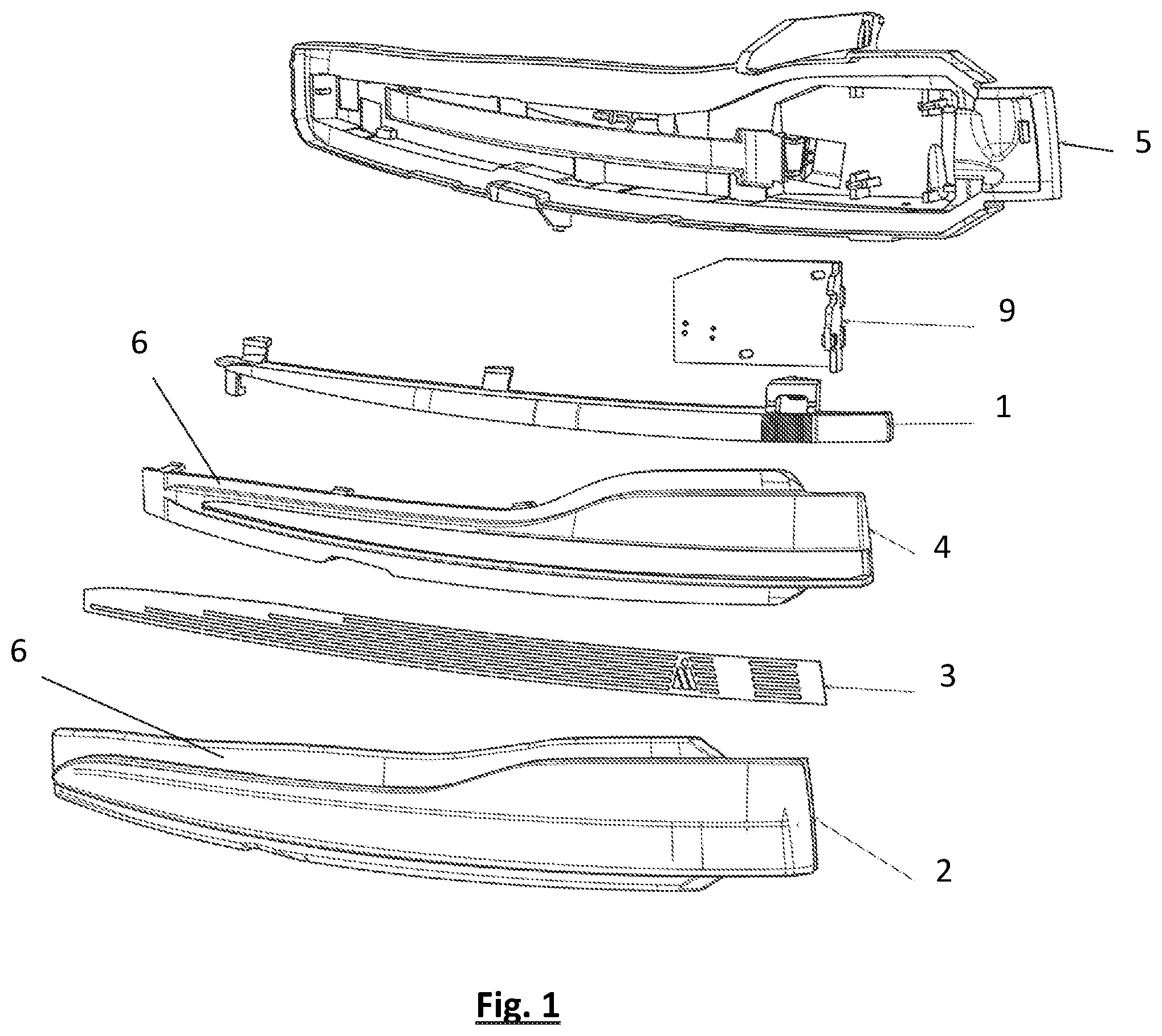
FIG. 1 is an exploded representation of a turn signal unit according to the invention for an external mirror.
FIG. 2 is a sectional view of a turn signal unit according to the invention in a further embodiment.
FIG. 3 is a sectional view of a turn signal unit according to the invention in a further embodiment.
DESCRIPTION OF THE PREFERRED EMBODIMENTS
In FIG. 1, a turn signal unit according to the invention for an external mirror for a motor vehicle is shown in an exploded representation. The turn signal unit comprises--looking in the direction of travel of the vehicle and in the illumination direction of the turn signal unit, which is at the upper edge of the image in FIG. 1--the following components from the rear forwards: a housing floor 5 that acts as a support for the turn signal unit, a control unit 9, which can be implemented as a PCBA (Printed Circuit Board Assembly) and that can form an electrical input or optical input for a light source, a light source 1, which is implemented as a light conductor, an aperture or element 4 that comprises in the centre thereof an opening for the passage of light and comprises a non-light transmissive frame, a film 3 with alternating light transmissive and non-light transmissive structures, i.e. a pattern that acts as a mask for the passage of light, and an at least partly light transmissive lens 2 forming the boundary and front housing component of the turn signal unit.
In the embodiment of FIG. 1, the film 3 is clamped between the flange surfaces 6 of the aperture or element 4 on the one hand and the lens 2 on the other hand and can thus in particular be simply removed from the turn signal unit following removal of the lens 2 and replaced.
FIG. 2 and FIG. 3 show further possibilities for the arrangement and clamping of the film 3 in a turn signal unit in sectional representations.
Here in FIG. 2 the film 3 is directly clamped between the lens 2 and the housing floor 5. In addition to mutually parallel flange surfaces 6, in said embodiment spring elements 7 are formed on the lens 2 to clamp the film 3.
The version of a turn signal unit represented in FIG. 3 comprises an aperture or element 4. The film 3 is clamped here by means of groove and spring elements 8, 7 of the aperture or element 4 and housing floor 5.
Of course, the film 3 can also be clamped by a plurality of elements, in particular by the interaction of the lens 2, aperture or element 4 and housing floor 5.
REFERENCE CHARACTER LIST
1 light source 2 lens 3 film 4 aperture or element 5 housing floor 6 flange 7 spring element 8 groove element 9 control unit
* * * * *
D00000
D00001
D00002
XML
uspto.report is an independent third-party trademark research tool that is not affiliated, endorsed, or sponsored by the United States Patent and Trademark Office (USPTO) or any other governmental organization. The information provided by uspto.report is based on publicly available data at the time of writing and is intended for informational purposes only.
While we strive to provide accurate and up-to-date information, we do not guarantee the accuracy, completeness, reliability, or suitability of the information displayed on this site. The use of this site is at your own risk. Any reliance you place on such information is therefore strictly at your own risk.
All official trademark data, including owner information, should be verified by visiting the official USPTO website at www.uspto.gov. This site is not intended to replace professional legal advice and should not be used as a substitute for consulting with a legal professional who is knowledgeable about trademark law.