Vehicle with supporting structure
Hofer
U.S. patent number 10,661,647 [Application Number 16/247,713] was granted by the patent office on 2020-05-26 for vehicle with supporting structure. This patent grant is currently assigned to MAGNA STEYR Fahrzeugtechnik AG & Co KG. The grantee listed for this patent is MAGNA STEYR Fahrzeugtechnik AG & Co KG. Invention is credited to Bernhard Hofer.


| United States Patent | 10,661,647 |
| Hofer | May 26, 2020 |
Vehicle with supporting structure
Abstract
A motor vehicle that includes a body having a support structure, a high-voltage battery having a battery housing and at least one battery module arranged in the battery housing. The battery housing is arranged on and attached to the support structure to serve as a main floor panel. A battery cover is detachably arranged on the underside of the battery housing to serve as underride protection and facilitate access to the at least one battery module.
| Inventors: | Hofer; Bernhard (Graz, AT) | ||||||||||
|---|---|---|---|---|---|---|---|---|---|---|---|
| Applicant: |
|
||||||||||
| Assignee: | MAGNA STEYR Fahrzeugtechnik AG
& Co KG (Graz, AT) |
||||||||||
| Family ID: | 60972124 | ||||||||||
| Appl. No.: | 16/247,713 | ||||||||||
| Filed: | January 15, 2019 |
Prior Publication Data
| Document Identifier | Publication Date | |
|---|---|---|
| US 20190217695 A1 | Jul 18, 2019 | |
Foreign Application Priority Data
| Jan 15, 2018 [EP] | 18151638 | |||
| Current U.S. Class: | 1/1 |
| Current CPC Class: | B60K 1/04 (20130101); H01M 2/043 (20130101); H01M 2/1083 (20130101); B62D 25/20 (20130101); B60K 2001/0472 (20130101); B60K 2001/0438 (20130101) |
| Current International Class: | B60K 1/04 (20190101); B62D 25/20 (20060101); H01M 2/04 (20060101); H01M 2/10 (20060101) |
| Field of Search: | ;180/68.5 |
References Cited [Referenced By]
U.S. Patent Documents
| 4365681 | December 1982 | Singh |
| 5390754 | February 1995 | Masuyama |
| 5501289 | March 1996 | Nishikawa |
| 5620057 | April 1997 | Klemen |
| 5639571 | June 1997 | Waters |
| 6227322 | May 2001 | Nishikawa |
| 6631775 | October 2003 | Chaney |
| 6632560 | October 2003 | Zhou |
| 7993155 | August 2011 | Heichal |
| 7997368 | August 2011 | Takasaki |
| 8006793 | August 2011 | Heichal |
| 8079435 | December 2011 | Takasaki |
| 8146694 | April 2012 | Hamidi |
| 8210301 | July 2012 | Hashimoto |
| 8268469 | September 2012 | Hermann |
| 8286743 | October 2012 | Rawlinson |
| 8336658 | December 2012 | Rawlinson |
| 8397853 | March 2013 | Stefani |
| 8464817 | June 2013 | Usami |
| 8469129 | June 2013 | Mildner |
| 8672354 | March 2014 | Kim |
| 8733487 | May 2014 | Usami |
| RE44994 | July 2014 | Rawlinson |
| 8776926 | July 2014 | Auer |
| 8789634 | July 2014 | Nitawaki |
| 8833499 | September 2014 | Rawlinson |
| 8835033 | September 2014 | Choi |
| 8875828 | November 2014 | Rawlinson |
| 8900744 | December 2014 | Loo |
| 8936125 | January 2015 | Nakamori |
| 8967312 | March 2015 | Yanagi |
| 8980458 | March 2015 | Honjo |
| 8993142 | March 2015 | Sakai |
| 9033084 | May 2015 | Joye |
| 9033085 | May 2015 | Rawlinson |
| 9045030 | June 2015 | Rawlinson |
| 9216638 | December 2015 | Katayama |
| 9758030 | September 2017 | Newman |
| 9761851 | September 2017 | Onodera |
| 9812746 | November 2017 | Katayama |
| 9862427 | January 2018 | Berger |
| 9987913 | June 2018 | Hara |
| 10017037 | July 2018 | Newman |
| 10023069 | July 2018 | Kobayashi |
| 10062876 | August 2018 | Wuensche |
| 10112470 | October 2018 | Hamilton |
| 10112563 | October 2018 | Ashraf |
| 10131247 | November 2018 | Berger |
| 10131381 | November 2018 | Ashraf |
| 10220694 | March 2019 | Mizoguchi |
| 10245955 | April 2019 | Nakayama |
| 10272759 | April 2019 | Sudhindra |
| 10272949 | April 2019 | Faruque |
| 10300948 | May 2019 | Ashraf |
| 2011/0240386 | October 2011 | Czinger et al. |
| 2012/0301765 | November 2012 | Loo |
| 102015205413 | Sep 2016 | DE | |||
| 2982579 | Feb 2016 | EP | |||
| 2014031168 | Feb 2014 | JP | |||
Attorney, Agent or Firm: Jordan IP Law, LLC Vaughn; Todd A.
Claims
What is claimed is:
1. A motor vehicle, comprising: a body having a support structure having a dip-coating; a high-voltage battery having a battery housing having a dip-coating, the battery housing including a battery housing frame, at least one battery module arranged in the battery housing, the battery housing being arranged on and attached to the support structure, the battery housing having a shape of a cuboid to serve as a main floor panel, and a battery housing cover detachably attached to the battery housing frame on the underside thereof as underride protection and facilitate access to the at least one battery module, wherein the support structure and the battery housing are dip-coated separately from one another.
2. The motor vehicle of claim 1, wherein the support structure comprises at least one seat crossmember, a rear seat crossmember, and a longitudinal tunnel structure.
3. The motor vehicle of claim 1, wherein the support structure comprises at least one seat crossmember, and/or at least one rear seat crossmember, and/or at least one longitudinal tunnel structure.
4. The motor vehicle of claim 1, wherein the support structure comprises at least one seat crossmember.
5. The motor vehicle of claim 1, wherein the support structure comprises at least one rear seat crossmember.
6. The motor vehicle of claim 1, wherein the support structure comprises at least one longitudinal tunnel structure.
7. The motor vehicle of claim 1, wherein the battery housing is attached to the support structure in a permanent and load-bearing manner via screws, rivets, and an assembly adhesive.
8. The motor vehicle of claim 1, wherein the battery housing is attached to the support structure in a permanent and load-bearing manner via screws.
9. The motor vehicle of claim 1, wherein the battery housing is attached to the support structure in a permanent and load-bearing manner via rivets.
10. The motor vehicle of claim 1, wherein the battery housing is attached to the support structure in a permanent and load-bearing manner via an assembly adhesive.
11. The motor vehicle of claim 1, wherein: at least one battery module is assembled on the battery housing cover; at least one battery module is attached to the top wall of the battery housing frame; and at least one battery module is attached to a side wall of the battery housing frame.
12. The motor vehicle of claim 1, wherein at least one battery module is assembled on the battery housing cover.
13. The motor vehicle of claim 1, wherein at least one battery module is attached to the top wall of the battery housing frame.
14. The motor vehicle of claim 1, wherein at least one battery module is attached to a side wall of the battery housing frame.
15. A motor vehicle, comprising: a high-voltage battery having at least one battery module; a battery housing, having a dip-coating, to serve as a main floor panel of the motor vehicle, the battery housing including a battery housing frame which is to receive therein the at least one battery module, wherein the battery housing is dip-coated separately from a support structure of the motor vehicle, and a battery housing cover detachably attached to the battery housing frame as underride protection and facilitate access to the at least one battery module, wherein the support structure and the battery housing are dip-coated separately from one another.
16. A battery assembly for a motor vehicle that includes a body having a support structure with a dip-coating, the battery assembly comprising: a high-voltage battery having at least one battery module; a battery housing, having a dip-coating, to serve as a main floor panel of the motor vehicle, the battery housing including a battery housing frame which is to receive therein the at least one battery module, and a battery housing cover detachably attached to the battery housing frame in a gas-tight manner as underride protection and facilitate access to the at least one battery module, wherein the support structure and the battery housing are dip-coated separately from one another.
Description
CROSS-REFERENCE TO RELATED APPLICATIONS
The present application claims priority 35 U.S.C. .sctn. 119 to European Patent Publication No. EP 18151638.6 (filed on Jan. 15, 2018), which is hereby incorporated by reference in its entirety.
TECHNICAL FIELD
Embodiments relate to a motor vehicle comprising a body having a support structure.
BACKGROUND
It is known that motor vehicles can utilise a support structure, in particular, comprising longitudinal members and crossmembers, as bodies. The support structure can then, in particular, form a so-called self-supporting body of the vehicle.
Vehicles usually use a floor plate or a floor panel, also known as a main floor, main floor plate, main floor panel, as the bottom delimitation of the vehicle. The main floor panel then usually likewise has a supporting function as a body component of the vehicle. The underside of such a main floor panel can also act as underride protection which protects the vehicle from contamination from underneath the vehicle.
In recent times, high-voltage batteries have been increasingly used as drive batteries for electric and hybrid vehicles. These high-voltage batteries are usually relatively large and must therefore be arranged in a space-saving manner in a vehicle.
SUMMARY
Embodiments relate to a motor vehicle which saves on installation space and components, and which may therefore be produced in a compact and cost-saving manner. In particular, such a motor vehicle may include a high-voltage battery to be arranged therein in a space-saving, yet still maintenance-friendly manner.
In accordance with embodiments, a motor vehicle may comprise at least one of: a body having a support structure; a high-voltage battery having a battery housing and at least one battery module in the battery housing, the battery housing being arranged on and attached to the support structure in such a way that the battery housing acts as a main floor panel; and a detachable battery cover arranged on the underside of the battery housing to acts as underride protection and also to facilitate accessibility to the at least one battery module.
In accordance with embodiments a motor vehicle may comprises at least one of: a body having a support structure, wherein the support structure or the body does not comprise a usual main floor panel.
In accordance with embodiments, the motor vehicle comprises a high-voltage battery having a battery housing and at least one battery module in the battery housing. The battery housing is arranged on and attached to the support structure in such a way that the battery housing itself acts as a main floor panel. The battery housing therefore forms a floor of the motor vehicle. The motor vehicle does not have a main floor panel which is independent of this, which also means that there are no clearances between a battery housing and a main floor. The battery housing substantially has the shape of a plate or a shallow cuboid so that it can replace the main floor. The high-voltage battery is therefore a shallow accumulator.
In accordance with embodiments, a detachable battery cover is arranged on the underside of the battery housing so that the at least one battery module is accessible via the battery cover, in particular, for purposes of maintenance and repair. In accordance with embodiments, "detachable" may mean the complete removal of the battery cover, or a swinging-open or folding-open of the battery cover so that, in any case, access to the battery modules is possible.
Since the battery cover represents the underside of the thus formed "main floor," the battery cover also acts as underride protection which protects the battery modules from damage, dirt, and debris.
In accordance with embodiments, a high-voltage battery is therefore arranged in an extremely space-saving manner in a vehicle. The battery housing moreover assumes a load-bearing function as a body component of the vehicle. In this case, battery modules and electronics within the battery housing remain easily accessible from the outside for replacement, repair etc.
In accordance with embodiments, the support structure may comprise at least one seat crossmember and/or rear seat crossmember and/or a longitudinal tunnel structure.
In accordance with embodiments, the battery housing is attached to the support structure in a permanent and load-bearing manner, for example, via screws, rivets, and/or an assembly adhesive. The battery housing remains connected to the support structure of the vehicle over the lifetime of the vehicle since it assumes part of the load path.
In accordance with embodiments, the support structure and the battery housing are preferably dip-coated separately from one another. The high-voltage battery, including battery modules, electronics, and necessary connecting cables, may be coated and assembled separately from the body of the vehicle and in parallel, i.e., simultaneously, therewith. The battery housing may be composed of metal. The surface treatment via dip-coating can serve for protection against corrosion and improve the bonding of an adhesive to the battery housing. The battery housing may be attached to the support structure via assembly adhesive and screws or rivets. The screw connection may be realised, for example, from below through the entire cross-section of the high-voltage battery, or from above.
In accordance with embodiments, at least one battery module is assembled on the battery cover and/or at least one battery module is attached to the top wall of the battery housing and/or at least one battery module is attached to a side wall of the battery housing.
In accordance with embodiments, the detachable battery cover may comprise parts of the side walls or the whole of the side walls of the battery housing, i.e., the frame of the battery housing, although the rest of the structure of the battery housing must have sufficient rigidity to prevent deformations of the vehicle during the detachment, in particular, the swinging-open or folding-open, of the battery cover.
In accordance with embodiments, the battery cover is detachably attached to the rest of the battery housing and/or to the support structure via screws, in particular, in a gas-tight manner. If the battery cover is screwed directly to the support structure, it may particularly enhance the rigidity and the crash behaviour of the body.
In accordance with embodiments, the terms "top" and "bottom" always refer to a motor vehicle in the usual position of use.
DRAWINGS
Embodiments will be illustrated by way of example in the drawings and explained in the description below.
FIG. 1 illustrates a three-dimensional illustration of the body and the high-voltage battery of a motor vehicle, in accordance with embodiments.
FIG. 2 illustrates a three-dimensional illustration of the high-voltage battery inserted into the body of (as seen from above) and as seen from below in the bottom.
FIG. 3 illustrates the body and the high-voltage battery of FIG. 2 in the assembled state.
FIG. 4 illustrates the body and the high-voltage battery of FIG. 3 with the battery cover in a detached state.
FIGS. 5A to 5D illustrates an assembled motor vehicle and its battery modules, and also variants of the attachment of the battery modules, in accordance with embodiments.
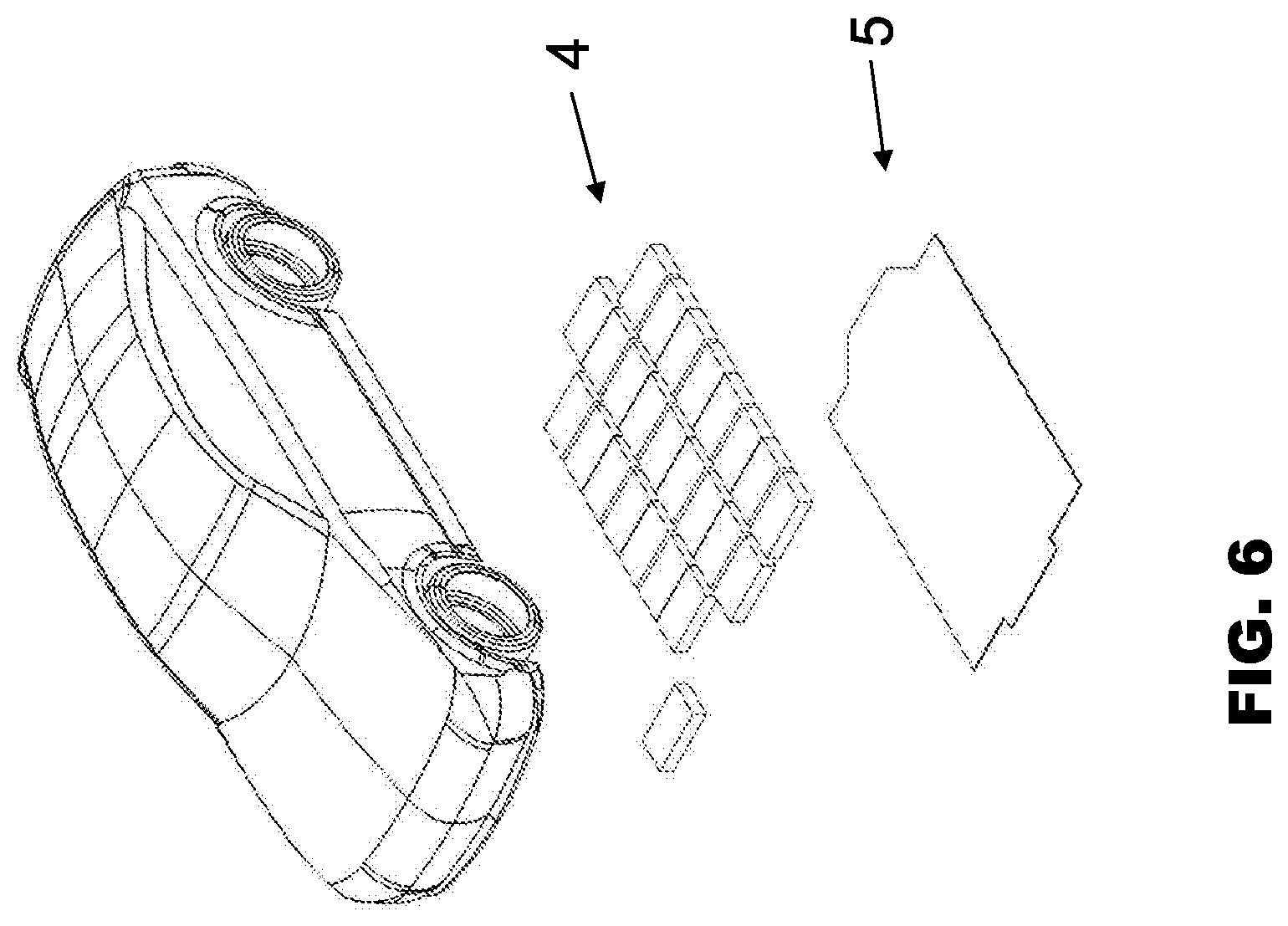
FIG. 6 illustrates the repair of a motor vehicle, in accordance with embodiments.
DESCRIPTION
FIGS. 1 through 4 illustrate a motor vehicle comprising a body 1 and a high-voltage battery with a battery housing 3, in accordance with embodiments. The body 1 comprises a support structure 2 having a plurality of longitudinal members and seat crossmembers and rear seat crossmembers, and a longitudinal tunnel structure. The body 1 also comprises panel components which form a roof of the motor vehicle, and pillars which connect the roof panels to the support structure 2. The body itself does not comprise a main floor panel.
The motor vehicle furthermore comprises a high-voltage battery in a battery housing 3 and a plurality of battery modules 4 arranged in the battery housing 3. The high-voltage battery may comprise a shallow accumulator. The battery housing 3 is arranged on and attached to the support structure 2 in such a way that the battery housing 3 acts as a main floor panel. The battery housing 3 therefore forms a floor of the motor vehicle. The battery housing 3 may be attached to the support structure 3 in a permanent and load-bearing manner via screws or rivets and additionally via assembly adhesive.
In accordance with embodiments, the support structure 2 and the high-voltage battery are produced independently of one another in parallel lines. The battery housing 3 may be dip-coated separately from the body 1 of the vehicle.
In accordance with embodiments, a detachable battery cover 5 is arranged on the underside of the battery housing 3 so that the battery modules 4 are accessible by detaching the battery cover 5. The battery cover 5 acts as underride protection and protects the battery modules from damage from underneath, i.e., from the road.
As illustrated in FIGS. 2 and 3, the components of FIG. 1, namely, the body 1 and the high-voltage battery in the assembled state are provided, wherein the view from above is illustrated in the top figure and the view from below, or an overturned vehicle, is illustrated in the bottom of the illustration.
As illustrated in FIG. 4, in contrast to FIG. 3, the detachment of the battery cover 5 from the rest of the battery housing 3 is provided. Between the battery cover 5 and the remainder of the walls of the battery housing 3, the battery modules are arranged and attached in a regular distribution in two dimensions, in the longitudinal and transverse direction.
As illustrated in FIGS. 5A to 5D, the battery modules 4 is a assembled in the illustrated motor vehicle. The attachment of the battery modules 4 may be realised, inter alia, in the variants of FIGS. 5B to 5D. In this case, at the time of attaching the battery cover 5 to the remainder of the battery housing 3 and/or to the support structure 2 during vehicle manufacture, the battery modules 4 are not yet assembled on the battery cover 5 (FIG. 5B) or are already pre-assembled on the battery cover 5 (FIG. 5C) or are already pre-assembled on the battery cover 5 which also comprises a frame, i.e., side walls of the battery housing 3. The battery modules 4 may already be pre-assembled in this manner in or on the battery housing 3 (FIG. 5C) or on other walls of the battery housing 3 at the time of attaching the battery cover 5.
The embodiment described with reference to FIG. 5B, in which the battery modules 4 are not yet assembled at the time of attaching the battery cover 5, is then especially advantageous if the attachment of the battery cover 5 to the remainder of the battery housing 3 does not yet include closing the battery cover, but instead constitutes connecting the cover to the battery housing, for example, via hinges or similar mechanisms, so that the battery cover can still be simply folded open and shut or simply opened in some other manner or is even still open after the attaching procedure.
After attaching the battery cover, depending on the variant embodiment, an additional procedure for sealing the battery by closing the battery cover 5, for example, in conjunction with a subsequent locking or screw-connection of the battery cover 5 to the remainder of the battery housing 3 and/or to the support structure 2, may be optionally realised.
As illustrated in FIG. 6, repair or maintenance of a motor vehicle may be realised, namely, by detaching the battery cover 5 so that the battery modules 4 may be removed, and repaired or replaced.
The terms "coupled," "connected" "fastened" or "attached" may be used herein to refer to any type of relationship, direct or indirect, between the components in question, and may apply to electrical, mechanical, fluid, optical, electromagnetic, electromechanical or other connections. In addition, the terms "first," "second," etc. are used herein only to facilitate discussion, and carry no particular temporal or chronological significance unless otherwise indicated.
This written description uses examples to disclose the invention, including the preferred embodiments, and also to enable any person skilled in the art to practice the invention, including making and using any devices or systems and performing any incorporated methods. The patentable scope of embodiments is defined by the claims, and may include other examples that occur to those skilled in the art. Such other examples are intended to be within the scope of the claims if they have structural elements that do not differ from the literal language of the claims, or if they include equivalent structural elements with insubstantial differences from the literal languages of the claims. Aspects from the various embodiments described, as well as other known equivalents for each such aspects, may be mixed and matched by one of ordinary skill in the art to construct additional embodiments and techniques in accordance with principles of this application.
LIST OF REFERENCE SYMBOLS
1 Body
2 Support structure
3 Battery housing
4 Battery module
5 Battery cover
* * * * *
D00000
D00001
D00002
D00003
D00004
XML
uspto.report is an independent third-party trademark research tool that is not affiliated, endorsed, or sponsored by the United States Patent and Trademark Office (USPTO) or any other governmental organization. The information provided by uspto.report is based on publicly available data at the time of writing and is intended for informational purposes only.
While we strive to provide accurate and up-to-date information, we do not guarantee the accuracy, completeness, reliability, or suitability of the information displayed on this site. The use of this site is at your own risk. Any reliance you place on such information is therefore strictly at your own risk.
All official trademark data, including owner information, should be verified by visiting the official USPTO website at www.uspto.gov. This site is not intended to replace professional legal advice and should not be used as a substitute for consulting with a legal professional who is knowledgeable about trademark law.